1
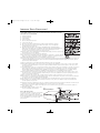
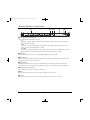
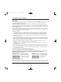
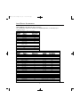
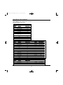
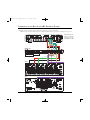
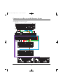
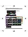
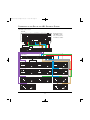
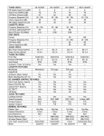
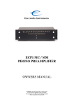
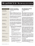
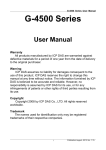
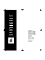
SDEC3000.4500.om.qxd
4/16/09
10:06 AM
Page 1
SYNTHESIS
®
SDEC-3000
SDEC-4500
DIGITAL
EQUALIZER
INSTALLER’S
MANUAL
SDEC3000.4500.om.qxd
4/16/09
10:06 AM
Page 2
CONTENTS
PRECAUTIONS . . . . . . . . . . . . . . . . . . . . . . . . . . . . . . . . . . . . . . . . . . . . . . . . . . . . . . . . . . . . . . . . . . . . . . . . . . . . . . . . . . . . . . .3
INTRODUCTION AND FEATURES . . . . . . . . . . . . . . . . . . . . . . . . . . . . . . . . . . . . . . . . . . . . . . . . . . . . . . . . . . . . . . . . . . . . . . . . . . . .4
DETAILED DIAGRAMS . . . . . . . . . . . . . . . . . . . . . . . . . . . . . . . . . . . . . . . . . . . . . . . . . . . . . . . . . . . . . . . . . . . . . . . . . . . . . . . . . .5
FRONT PANEL . . . . . . . . . . . . . . . . . . . . . . . . . . . . . . . . . . . . . . . . . . . . . . . . . . . . . . . . . . . . . . . . . . . . . . . . . . . . . .5
REAR PANEL . . . . . . . . . . . . . . . . . . . . . . . . . . . . . . . . . . . . . . . . . . . . . . . . . . . . . . . . . . . . . . . . . . . . . . . . . . . . . . .6
INPUT/OUTPUT ASSIGNMENTS . . . . . . . . . . . . . . . . . . . . . . . . . . . . . . . . . . . . . . . . . . . . . . . . . . . . . . . . . . . . . . . . . . . . . . . . . . .7
SDEC-3000 . . . . . . . . . . . . . . . . . . . . . . . . . . . . . . . . . . . . . . . . . . . . . . . . . . . . . . . . . . . . . . . . . . . . . . . . . . . . . . .7
SDEC-4500 . . . . . . . . . . . . . . . . . . . . . . . . . . . . . . . . . . . . . . . . . . . . . . . . . . . . . . . . . . . . . . . . . . . . . . . . . . . . . . .8
SDEC-4500 WITH BI-AMPLIFIED FRONT SPEAKERS . . . . . . . . . . . . . . . . . . . . . . . . . . . . . . . . . . . . . . . . . .9
SDEC-4500 WITH FULL-RANGE FRONT SPEAKERS . . . . . . . . . . . . . . . . . . . . . . . . . . . . . . . . . . . . . . . . . .10
CONNECTION TO THE REST OF THE JBL SYNTHESIS ® SYSTEM . . . . . . . . . . . . . . . . . . . . . . . . . . . . . . . . . . . . . . . . . . . . . . . . . . . . .11
SDEC-3000 . . . . . . . . . . . . . . . . . . . . . . . . . . . . . . . . . . . . . . . . . . . . . . . . . . . . . . . . . . . . . . . . . . . . . . . . . . . . . .11
SYNTHESIS TWO ARRAY ™ . . . . . . . . . . . . . . . . . . . . . . . . . . . . . . . . . . . . . . . . . . . . . . . . . . . . . . . . . . . .11
SYNTHESIS THREE ARRAY . . . . . . . . . . . . . . . . . . . . . . . . . . . . . . . . . . . . . . . . . . . . . . . . . . . . . . . . . . . .11
SYNTHESIS FOUR . . . . . . . . . . . . . . . . . . . . . . . . . . . . . . . . . . . . . . . . . . . . . . . . . . . . . . . . . . . . . . . . . .11
SYNTHESIS PROJECT ARRAY ™ . . . . . . . . . . . . . . . . . . . . . . . . . . . . . . . . . . . . . . . . . . . . . . . . . . . . . . . . .11
SDEC-4500 . . . . . . . . . . . . . . . . . . . . . . . . . . . . . . . . . . . . . . . . . . . . . . . . . . . . . . . . . . . . . . . . . . . . . . . . . . . . .12
SYNTHESIS ONE ARRAY . . . . . . . . . . . . . . . . . . . . . . . . . . . . . . . . . . . . . . . . . . . . . . . . . . . . . . . . . . . . .12
SYNTHESIS ATLAS™ . . . . . . . . . . . . . . . . . . . . . . . . . . . . . . . . . . . . . . . . . . . . . . . . . . . . . . . . . . . . . . . .12
SYNTHESIS K2 ® . . . . . . . . . . . . . . . . . . . . . . . . . . . . . . . . . . . . . . . . . . . . . . . . . . . . . . . . . . . . . . . . . .13
SYNTHESIS EVEREST . . . . . . . . . . . . . . . . . . . . . . . . . . . . . . . . . . . . . . . . . . . . . . . . . . . . . . . . . . . . . . .14
TECHNICAL SPECIFICATIONS . . . . . . . . . . . . . . . . . . . . . . . . . . . . . . . . . . . . . . . . . . . . . . . . . . . . . . . . . . . . . . . . . . . . . . . . . . . . .15
2
SDEC3000.4500.om.qxd
4/16/09
10:06 AM
Page 3
IMPORTANT SAFETY PRECAUTIONS!
PLEASE READ CAREFULLY ALL OF THE FOLLOWING IMPORTANT SAFEGUARDS THAT ARE
APPLICABLE TO YOUR EQUIPMENT
1.
2.
3.
4.
5.
6.
7.
8.
Read these instructions.
Keep these instructions.
Heed all warnings.
Follow all instructions.
Do not use this apparatus near water.
Clean only with a dry cloth.
Do not block any ventilation openings. Install in accordance with the manufacturer’s instructions.
Do not install near any heat sources such as radiators, heat registers, stoves or other apparatus
(including amplifiers) that produce heat.
9. Do not defeat the safety purpose of the polarized or grounding-type plug. A polarized plug has two
blades with one wider than the other. A grounding-type plug has two blades and a third grounding prong.
The wide blade or the third prong is provided for your safety. If the provided plug does not fit into
your outlet, consult an electrician for replacement of the obsolete outlet.
10. Protect the power cord from being walked on or pinched, particularly at plugs, convenience receptacles and
the point where they exit from the apparatus.
11. Only use attachments/accessories specified by the manufacturer.
12. Use only with the cart, stand, tripod, bracket or table specified by the manufacturer or sold with the apparatus.
When a cart is used, use caution when moving the cart/apparatus combination to avoid injury from tip-over.
13. Unplug this apparatus during lightning storms or when unused for long periods of time.
14. Refer all servicing to qualified service personnel. Servicing is required when the apparatus has been damaged in any way, such as power-supply cord
or plug is damaged, liquid has been spilled or objects have fallen into the apparatus, the apparatus has been exposed to rain or moisture, does not
operate normally, or has been dropped.
15. Do not use attachments not recommended by the product manufacturer, as they may cause hazards.
16. This product should be operated only from the type of power source indicated on the marking label. If you are not sure of the type of power supply
to your home, consult your product dealer or local power company. For products intended to operate from battery power, or other sources, refer to
the operating instructions.
17. If an outside antenna or cable system is connected to the product, be sure the antenna or cable system is grounded so as to provide some protection
against voltage surges and built-up static charges. Article 810 of the National Electrical Code, ANSI/NFPA 70, provides information with regard to
proper grounding of the mast and supporting structure, grounding of the lead-in wire to an antenna discharge unit, size of grounding conductors,
location of antenna-discharge unit, connection to grounding electrodes, and requirements for the grounding electrode. See Figure A.
18. An outside antenna system should not be located in the vicinity of overhead power lines or other electric light or power circuits, or where it can fall
into such power lines or circuits. When installing an outside antenna system, extreme care should be taken to keep from touching such power lines or
circuits, as contact with them might be fatal.
19. Do not overload wall outlets, extension cords, or integral convenience receptacles, as this can result in a risk of fire or electric shock.
20. Never push objects of any kind into this product through openings, as they may touch dangerous voltage points or short-out parts that could result in
a fire or electric shock. Never spill liquid of any kind on the product.
21. The apparatus shall not be exposed to dripping or splashing, and no objects filled with liquids, such as vases, shall be placed on the apparatus.
22. Do not attempt to service this product yourself, as opening or removing covers may expose you to dangerous voltage or other hazards. Refer all
servicing to qualified service personnel.
23. When replacement parts are required, be sure the service technician has used replacement parts specified by the manufacturer or that have the same
characteristics as the original part. Unauthorized substitutions may result in fire, electric shock or other hazards.
24. Upon completion of any service or repairs to this product, ask the service technician to perform safety checks to determine that the product is in
proper operating condition.
25. The product should be mounted to a wall or ceiling
only as recommended by the manufacturer.
Figure A.
Example of Antenna Grounding as per
National Electrical Code ANSI/NFPA 70
Note to CATV system installer:
This reminder is provided to call the CATV system installer’s
attention to Article 820-22 of the NEC that provides
guidelines for proper grounding and, in particular, specifies
that the cable ground shall be connected to the grounding
system of the building, as close to the point of cable
entry as practical.
3
SDEC3000.4500.om.qxd
4/16/09
10:06 AM
Page 4
INTRODUCTION AND FEATURES
INTRODUCTION
Congratulations on your purchase of this JBL Synthesis® SDEC Digital Equalizer! You have chosen a product that
embodies the best of what JBL, Inc., has discovered about the emotional power of audio reproduction in more than
sixty years of preeminence in the field. This Digital Equalizer has been designed and crafted to provide the user
with a high level of sonic performance. Special attention has been paid to minimize the number of components in
the audio signal path, resulting in extremely low distortion, excellent transient response and wide dynamic range.
Synthesis® products set new benchmarks in audio technology, and, when used as part of a complete JBL Synthesis
system, will bring the ambience and acoustics of some of the world’s greatest concert halls and theaters into your
home. To obtain the best performance from this Digital Equalizer, please be sure to completely read this user’s
manual and use the SDEC Digital Equalizer only in accordance with its instructions.
From its inception, JBL Synthesis has been the answer to the questions: “How do you build a state-of-the-art home
theater system and make it sound superb in every installation?” and “How can you be sure all the hardware is compatible?”
These were the big questions Synthesis components answered fifteen years ago. Today, JBL Synthesis systems
move beyond the competition yet again. The JBL Synthesis Digital Equalizer (SDEC) is a 12-channel-in/20-channel-out
24-bit, 96kHz digital audio signal processor. Unlike nearly all other audio components on the market, the SDEC has
been designed to work specifically with other Synthesis system components. This narrow application focus has
allowed JBL engineers to design a product with far fewer compromises, resulting in unequalled system performance.
By reading the following pages, you will become familiar with the technological features and unique capabilities
incorporated within the SDEC and available nowhere else.
Until now, anything beyond the most basic equalization has been impossible without expensive acoustical instrumentation and the knowledge to use it. This is why, traditionally, equalizers have been general-purpose devices,
designed to be applicable to any audio system, and usually doing more harm than good! Add to this situation the
fact that equalizing a speaker system by ear is truly a futile exercise. This helps to account for the generally low
acceptance of equalizers outside of professional audio applications.
FEATURES
• Up to 256 bands of fully parametric EQ
• Built-in crossover for bi-amp outputs (SDEC-4500 only)
• Delay adjustment for each output
• Delay adjustment for driver compensation
• Screen compensation
• Driver compensation
• Web-based Java remote for basic system setup
• Windows application for advanced system setup
• Custom configuration possible
• Remote VPN monitoring
• Four subwoofer outputs (SDEC-4500 only)
• Three pairs of side speaker outputs for large rooms with multiple rows of seating (SDEC-4500 only)
• 24-Bit DSP
• 96kHz sample rate on all inputs and outputs
• Balanced or single-ended (unbalanced) inputs and outputs
4
SDEC3000.4500.om.qxd
4/16/09
10:06 AM
Page 5
DETAILED DIAGRAM – FRONT PANEL
2
0
31
4
56
0 INPUT/OUTPUT CARD MONITORING
Each channel has three LED indicators showing:
CLIP
Illuminated – Indicates clipping in the analog domain for each channel of the fitted input or output card.
The LED will light at +18.5dB.
SIGNAL
Illuminated – The signal LED will light for each channel of a fitted input or output card when the signal
reaches or exceeds the signal threshold of – 20dB.
SYNC/48V
This feature is currently not supported by JBL Synthesis (lights to indicate that + 48V “phantom” power has
been activated for the relevant channel of a fitted input card or that Digital Sync is valid).
1 USB PORT
This is currently for future use and is not supported (SDEC 4500 does not include USB).
2 DATA ACTIVITY
The data activity LED will flash to indicate that the device is communicating with another control device, either
on the network or via the serial or control ports.
3 NETWORK LINK
The network link LED indicates the presence of Ethernet cables. If no cables are connected, the LED is unlit.
The network link is used for configuring and calibrating the Synthesis system when using the DACS calibration.
4 LCD (LIQUID CRYSTAL DISPLAY)
The LCD indicates the name/ID and IP address of the unit.
5 HOLD
Pressing and holding the Hold switch will cycle the LCD through its contrast range.
6 LOCATE
Pressing the Locate switch on the front of the unit will illuminate the Locate switch on the rear.
5
SDEC3000.4500.om.qxd
4/16/09
10:06 AM
Page 6
DETAILED DIAGRAM – REAR PANEL
SDEC-3000
SDEC-4500P and
SDEC-4500X
7
8
B
9 A
C
D
BlueLink
SDEC-3000 has no BlueLink™ connections, but is otherwise identical to the SDEC-4500P and SDEC-4500X.
7 AC MAINS
AC Mains input to the universal switched-mode power supply; operates over a wide range of AC input voltages
from 85V to 270V, 50/60Hz.
8 LOCATE
Pressing the Locate switch on the rear of the unit will illuminate the Locate switch on the front and identify the
device within the DACS software.
9 RS-232
Serial port for connection of external calibration and configuration equipment not used at this time.
A ETHERNET
The main connection for the proprietary system control network, and for third-party Ethernet control. The SDEC
must be connected to an Ethernet hub during the calibration process.
B BLUELINK™ CONNECTORS (SDEC-4500 ONLY)
The SDEC-4500P and SDEC-4500X use BlueLink to send and receive audio data.
Please Note: When using the SDEC-4500, you must connect the two units through the BlueLink connection, using
a Cat. 5e patch cable.
C CONTROL INPUTS
The SDEC-4500 can be configured for full-range or bi-amp operation by using these control inputs. The SDEC-3000
does not need or use this connection.
D INPUT/OUTPUT CARD POSITIONS A, B, C AND D
These connectors provide the balanced and unbalanced connections for the input/output card fitted in the four card
slots in a JBL Synthesis SDEC device. A green LED next to the slot assignment letter A, B, C or D indicates that an
input card is fitted and an amber LED when an output card is fitted. The analog connections are balanced/unbalanced,
on Phoenix/Combicon connectors. Depending on which model and configuration you have purchased will determine
which input/output card has been installed at the factory. Please make sure to order the correct wiring kit, either
S3000IC or S4500IC, with your system.
6
SDEC3000.4500.om.qxd
4/16/09
10:06 AM
Page 7
INPUT/OUTPUT ASSIGNMENTS
SDEC-3000
The SDEC-3000 supports up to 7.1 input with up to 7.1 output. The input and output assignments are described
in the below chart. You must make the correct connections from the surround processor output to the amplifier input
for the system to work correctly. Please refer to the connection diagram for more information.
The correct Synthesis Interconnect kit includes all the necessary connections for using the SDEC in the Synthesis
system. Please be sure to order the S3000IC or S3000XLRIC for use with SDEC-3000 and S4000IC or S4500XLRIC for use
with SDEC-4500. Retrofit kits are also available. Please contact JBL Synthesis Technical Support for more information
at 516.594.0300 (USA only).
CONNECTION NOTES
• Please follow the wiring diagram and the Input/Output Assignments chart for correct connections.
• You will need to use the Ethernet network port on the rear panel of the unit for the final calibration process.
You can connect the SDEC-3000 through any standard Ethernet hub.
• When using the SDP-40HD processor, make sure the subwoofer (in speaker setup) is set to Mono output and
connect to the Subwoofer Left output. Do not use LFE output.
Input/Output Assignments
Surround Processor to SDEC-3000 Inputs
S3000IC
Number
Channel
SDEC-3000
1
LEFT FRONT
A1
2
RIGHT FRONT
A2
3
CENTER FRONT
A3
4
LEFT SIDE
A4
5
RIGHT SIDE
B1
6
LEFT REAR
B2
7
RIGHT REAR
B3
8
SUBWOOFER
B4
(Mono Sub Left)
SDEC-3000 Outputs to Amplifiers
S3000IC
Number
Channel
9
LEFT FRONT
10
RIGHT FRONT
11
CENTER FRONT
12
LEFT SIDE
13
RIGHT SIDE
14
LEFT REAR
15
RIGHT REAR
16
SUBWOOFER
SDEC-3000
C1
C2
C3
C4
D1
D2
D3
D4
7
SDEC3000.4500.om.qxd
4/16/09
10:06 AM
Page 8
INPUT/OUTPUT ASSIGNMENTS
SDEC-4500
The SDEC-4500 comprises two units. Both the SDEC-4500P and SDEC-4500X are required for the digital equalizer
to function properly in the Synthesis system. Please be sure to connect both units correctly according to the
Input/Output Assignments chart on page 9.
The correct Synthesis Interconnect kit includes all the necessary connections for using the SDEC in the Synthesis
system. Please be sure to order the S3000IC or S3000XLRIC for use with SDEC-3000 and S4000IC or S4500XLRIC for use
with SDEC-4500. Retrofit kits are also available. Please contact JBL Synthesis Technical Support for more information
at 516.594.0300 (USA only).
The SDEC-4500 is capable of processing up to 12 inputs and up to 20 outputs. Depending on the type and number
of outputs will determine which connections you should use to connect the SDEC to the rest of your system. Please
refer to the connection diagram for more information.
CONNECTION NOTES
• The SDEC-4500 can process two outputs for the front left, center and right channels to output to an amplifier
for a bi-amplified system. There are discrete outputs for a single high-frequency horn speaker (SAM1HF) and
low-frequency (SAM2LF) speakers. These outputs can only be used with speakers designed to be used with
an external crossover. Do not use the SDEC Digital Equalizer for any speakers other than the recommended
Synthesis speaker packages.
• There are three pairs of outputs for side speakers. If you are only using one pair of side speakers, then you may
leave the second or third pair of outputs with no connection. If you are using a second or third pair of side speakers,
then you should connect the pair closest to the front speakers to Output 1, the pair in the middle of the room to
Output 2, and the pair closest to the rear speakers to Output 3.
• There are up to four subwoofer outputs. You should use them in pairs so that you either have two or four
subwoofers. All Synthesis systems are designed for at least two subwoofers.
• You must connect the SDEC-4500P and the SDEC-4500X using the BlueLink connection, using an Ethernet
network patch cable, Cat. 5e minimum.
• The two units must be connected to an Ethernet network hub for the final calibration process. Both units need
to be connected to the same hub or router, and an open port needs to be accessible for the calibration computer.
• When using the SDP-40HD processor, make sure the subwoofer (in speaker setup) is set to Mono output and connect to the Subwoofer Left output.
SELECTING FULL-RANGE OR BI-AMPED CONFIGURATION
There are two ways to select between bi-amped or full-range LCR operation.
Please note: Only Method One can be done on the control ports (without a computer). Method Two requires a computer running
the appropriate configuration software. Please contact JBL Synthesis Technical Support for more information.
METHOD ONE: WITHOUT A COMPUTER
Full Range: With the SDEC powered up and running,
connect Control Input 1 to “C” (common) on the back of
the unit for full range. This
is a temporary contact and
should not be left in place.
Bi-Amped: With the SDEC powered up and running,
connect Control Input 2 to “C” for bi-amped. This is
a temporary connection
and should not be
left in place.
METHOD TWO: WITH A COMPUTER
While online and in Operate mode from within London Architect™ or when using the Java remote, select the appropriate
speaker configuration as your installation requires. The software will automatically configure the outputs correctly.
8
SDEC3000.4500.om.qxd
4/16/09
10:06 AM
Page 9
INPUT/OUTPUT ASSIGNMENTS
SDEC-4500 WITH BI-AMPLIFIED FRONT SPEAKERS
This configuration requires the selection of bi-amplified operation, as noted on page 8.
Input/Output Assignments
Surround Processor to SDEC-4500P Inputs
S4500IC
Number
Channel
SDEC-4500P
1
FRONT LEFT
A1
2
FRONT RIGHT
A2
3
CENTER FRONT
A3
4
LEFT SIDE
A4
5
RIGHT SIDE
B1
6
LEFT REAR
B2
7
RIGHT REAR
B3
8
SUBWOOFER
B4
(Mono Sub L)
N/C
C1
N/C
C2
N/C
C3
N/C
C4
SDEC-4500X Outputs to Amplifiers
S4500IC
Number
Channel
SDEC-4500X
9
LEFT FRONT-LOW
A1
10
LEFT FRONT-HI
A2
11
RIGHT FRONT-LOW
A3
12
RIGHT FRONT-HI
A4
13
CENTER FRONT-LOW
B1
14
CENTER FRONT-HI
B2
15
LEFT SIDE 1
B3
16
RIGHT SIDE 2
B4
17
LEFT SIDE 2
C1
18
RIGHT SIDE 2
C2
19
LEFT SIDE 3
C3
20
RIGHT SIDE 3
C4
21
LEFT REAR
D1
22
RIGHT REAR
D2
AUX L
D3
AUX R
D4
Amplifier
S7165 #1
S7165 #1
S7165 #1
S7165 #1
S7165 #1
S7165 #1
S7165 #2
S7165 #2
S7165 #2
S7165 #2
S7165 #2
S7165 #2
S7165 #1
S7165 #2
–
–
SDEC-4500P Outputs to Amplifiers
Number
Channel
SDEC-4500P
23
SUBWOOFER 1
D1
24
SUBWOOFER 2
D2
25
SUBWOOFER 3
D3
26
SUBWOOFER 4
D4
S820 #1
S820 #2
S820 #3 (optional)
S820 #4 (optional)
9
Input Channel
CH1
CH2
CH3
CH4
CH5
CH6
CH1
CH2
CH3
CH4
CH5
CH6
CH7
CH7
–
–
CH1 (bridged)
CH1 (bridged)
CH1 (bridged)
CH1 (bridged)
SDEC3000.4500.om.qxd
4/16/09
10:06 AM
Page 10
INPUT/OUTPUT ASSIGNMENTS
SDEC-4500 WITH FULL-RANGE FRONT SPEAKERS
This is the default configuration.
Input/Output Assignments
Surround Processor to SDEC-4500P Inputs
S4500IC
Number
Channel
SDEC-4500P
1
FRONT LEFT
A1
2
FRONT RIGHT
A2
3
CENTER FRONT
A3
4
LEFT SIDE
A4
5
RIGHT SIDE
B1
6
LEFT REAR
B2
7
RIGHT REAR
B3
8
SUBWOOFER
B4
(Mono Sub L)
N/C
C1
N/C
C2
N/C
C3
N/C
C4
SDEC-4500X Outputs to Amplifiers
S4500XLRIC
Number
Channel
SDEC-4500X
9
LEFT FRONT
A1
10
N/C
A2
11
RIGHT FRONT
A3
12
N/C
A4
13
CENTER FRONT
B1
14
N/C
B2
15
LEFT SIDE 1
B3
16
RIGHT SIDE 1
B4
17
LEFT SIDE 2
C1
18
RIGHT SIDE 2
C2
19
LEFT SIDE 3
C3
20
RIGHT SIDE 3
C4
21
LEFT REAR
D1
22
RIGHT REAR
D2
AUX L
D3
AUX R
D4
Amplifier
S820 #1
–
S820 #2
–
S820 #3
–
S7165 #1
S7165 #1
S7165 #1
S7165 #1
–
–
S7165 #1
S7165 #1
–
–
Input Channel
CH1 (bridged)
–
CH1 (bridged)
–
CH1 (bridged)
–
CH1
CH2
CH3
CH4
–
–
CH5
CH6
–
–
SDEC-4500P Outputs to Amplifiers
S4500IC
Number
Channel
SDEC-4500P
23
SUBWOOFER 1
D1
24
SUBWOOFER 2
D2
25
SUBWOOFER 3
D3
26
SUBWOOFER 4
D4
S820 #4
S820 #5
S820 #6
S820 #7
CH1 (bridged)
CH1 (bridged)
CH1 (bridged)
CH1 (bridged)
10
SDEC3000.4500.om.qxd
4/16/09
10:06 AM
Page 11
CONNECTION TO THE REST OF THE JBL SYNTHESIS SYSTEM
SDEC-3000: Synthesis Two Array*, Synthesis Three Array, Synthesis Four, Synthesis Project Array
*NOTE: If using the Synthesis Two Array, please see SAM1HF/SAM2LF manual for connection of SAM12x passive crossover.
SDP-5
INPUTS
1
2
Y
MAIN
ZONE 2
VIDEO
VIDEO
SDP-5 Digital Surround Processor/Controller
JBL, Inc. Northridge, CA
Assembled in USA
INPUT 2
INPUT 1
VIDEO
S/PDIF INPUTS
PR
Y
PB
PR
4
4
3
5
S-VIDEO
3
4
Y
PR
Y
PB
PR
2
3
4
5
6
7
8
(L)
(C)
(LS)
(L)
(C)
(LS)
(R)
(SUB)
(RS)
(R)
(SUB)
(RS)
AUDIO
L
RS-232
PB
ATTENTION
1
TRIGGER
OUTPUTS
1
CAUTION
RISK OF ELECTRIC SHOCK
DO NOT OPEN
RISQUE DE CHOC
ELECTRIQUE
NE PAS OUVRIR
OUTPUT
INPUT 3
IR IN
S/PDIF
OUT
US
C
2
1
S/N
3
TUV
PB
2
1
R
CENTER
FRONT
L
L
R
R
2
AUDIO
REAR
SIDE
SUBWOOFER
OUTPUTS
1
2
AC 100-240V ~ 50-60 HZ, 60W
SDEC-3000
To Ethernet hub
(for system calibration)
S7165
CHASSIS
GROUND
6
7
TRIGGER
PUSH
2
1
3
PUSH
PUSH
1
2
1
2
3
3
2
1
2
PUSH
PUSH
PUSH
1
2
1
2
3
3
3
PUSH
OUT
IN
3-24 VDC
1
3
T8AL, 250V
8A SLO-BLO
FUSE
T8AL, 250V
8A SLO-BLO
FUSE
120V
60Hz
1200W
7
6
S820
820
CHASSIS
GROUND
1
MODE
1
STEREO
3
PUSH
3
PUSH
BRIDGED
MONO
TRIGGER
OUT
IN
3-24 VDC
2
2
BRIDGED
T6.3AL, 250V
6.3A SLO-BLO
FUSE
T6.3AL, 250V
6.3A SLO-BLO
FUSE
BRIDGED
MINIMUM IMPEDANCE
8 OHMS BRIDGED MONO
ATTENTION: VOIR LE CAHIER D'INSTRUCTION
MINIMUM IMPEDANCE
4 OHMS STEREO
120V
60Hz
800W
11
WARNING: FOR CONTINUED PROTECTION AGAINST RISK OF FIRE
REPLACE WITH SAME TYPE OF FUSE AND RATING
ATTENTION: UTILISER UN FUSIBLE DE RECHANGE DE MÉME TYPE REGLAGE CORRECT
7165
NOTE: Although the
SDP-5 is shown here,
connections for the
SDP-40HD are similar.
SDEC3000.4500.om.qxd
4/16/09
10:06 AM
Page 12
CONNECTION TO THE REST OF THE JBL SYNTHESIS SYSTEM
SDEC-4500: Synthesis One Array, Synthesis Atlas
SDP-40HD
2
3
INPUTS
4
INPUT 1
5
Y
VIDEO
1
PR
COMPONENT VIDEO
INPUT 2
PB
Y
PR
Y
PR
PB
S-VIDEO
MAIN OUTPUTS
INPUT 3
Y
PR
INPUT 4
Y
RECORD OUTPUTS
PB
2
1 (OSD)
OUTPUT
PB
PR
1
VIDEO
2
AUDIO
1
3
4
5
7
8
CENTER
FRONT
SIDE
SUBWOOFER
REAR
L
(L)
L
(C)
(LS)
L
L
L
L
R
(R)
R
(SUB)
(RS)
R
R
R
R
4
1
2
3
4
5
6
LFE
MICROPHONE INPUTS
1
3
S/PDIF
2
5
2
3
VIDEO
Fix
Fix ZONE 2 Var
AUX
L
R
1
AES/EBU
6
2
PB
AUDIO
MAIN AUDIO OUTPUTS
Var
AUDIO
TRIGGER OUTPUTS
4
S/PDIF
1
2
IR IN
6
MAIN
AUDIO
OUTPUTS
RS 232
L
FRONT
CENTER
R
L SUBWOOFER R
LFE
L
L
R
SIDE
R
REAR
L
R
AUX
L
ZONE 2
R
To Ethernet hub
(for system calibration)
SDEC-4500P
SDEC-4500X
To Ethernet hub
(for system calibration)
CHASSIS
GROUND
6
7
TRIGGER
PUSH
PUSH
PUSH
1
2
1
2
3
1
2
3
PUSH
PUSH
PUSH
1
2
3
1
2
PUSH
1
2
OUT
IN
3-24 VDC
1
2
3
3
3
T8AL, 250V
8A SLO-BLO
3
FUSE
T8AL, 250V
8A SLO-BLO
FUSE
WARNING: FOR CONTINUED PROTECTION AGAINST RISK OF FIRE
REPLACE WITH SAME TYPE OF FUSE AND RATING
ATTENTION: UTILISER UN FUSIBLE DE RECHANGE DE MÉME TYPE REGLAGE CORRECT
7165
120V
60Hz
1200W
6
7
S7165
CHASSIS
GROUND
6
7
TRIGGER
PUSH
PUSH
PUSH
1
2
1
2
3
3
1
2
PUSH
PUSH
PUSH
1
2
3
1
2
PUSH
1
2
OUT
IN
3-24 VDC
1
2
3
3
3
3
T8AL, 250V
8A SLO-BLO
FUSE
T8AL, 250V
8A SLO-BLO
FUSE
WARNING: FOR CONTINUED PROTECTION AGAINST RISK OF FIRE
REPLACE WITH SAME TYPE OF FUSE AND RATING
ATTENTION: UTILISER UN FUSIBLE DE RECHANGE DE MÉME TYPE REGLAGE CORRECT
7165
120V
60Hz
1200W
6
7
S7165
CHASSIS
GROUND
3
BRIDGED
1
1
2
1
MODE
BRIDGED
MONO
STEREO
T6.3AL, 250V
6.3A SLO-BLO
T6.3AL, 250V
6.3A SLO-BLO
FUSE
FUSE
T6.3AL, 250V
6.3A SLO-BLO
T6.3AL, 250V
6.3A SLO-BLO
FUSE
FUSE
BRIDGED
BRIDGED
MINIMUM IMPEDANCE
8 OHMS BRIDGED MONO
MINIMUM IMPEDANCE
4 OHMS STEREO
S820
TRIGGER
OUT
IN
3-24 VDC
3
1
820
3
PUSH
TRIGGER
OUT
IN
3-24 VDC
PUSH
3
PUSH
STEREO
2
2
MODE
BRIDGED
MONO
PUSH
CHASSIS
GROUND
BRIDGED
2
820
MINIMUM IMPEDANCE
8 OHMS BRIDGED MONO
ATTENTION: VOIR LE CAHIER D'INSTRUCTION
MINIMUM IMPEDANCE
4 OHMS STEREO
120V
60Hz
800W
S820
(BRIDGED)
12
(BRIDGED)
ATTENTION: VOIR LE CAHIER D'INSTRUCTION
120V
60Hz
800W
SDEC3000.4500.om.qxd
4/16/09
10:06 AM
Page 13
CONNECTION TO THE REST OF THE JBL SYNTHESIS SYSTEM
SDEC-4500: Synthesis K2
SDP-40HD
2
INPUTS
3
4
INPUT 1
5
Y
VIDEO
1
PR
INPUT 2
PB
Y
PR
COMPONENT VIDEO
PB
Y
S-VIDEO
Y
PR
MAIN OUTPUTS
INPUT 3
PR
INPUT 4
PB
Y
RECORD OUTPUTS
1 (OSD)
PR
2
1
3
4
5
6
7
8
CENTER
FRONT
SIDE
SUBWOOFER
REAR
Fix ZONE 2
AUX
L
L
(L)
L
(C)
(LS)
L
L
L
L
R
R
(R)
R
(SUB)
(RS)
R
R
R
R
2
3
1
S/PDIF
AES/EBU
AUDIO
2
Var
Fix
4
5
1
2
3
4
5
6
LFE
MICROPHONE INPUTS
1
2
3
2
PB
VIDEO
1
NOTE: Although the
SDP-40HD is shown
here, connections for
the SDP-5 are similar.
PB
OUTPUT
VIDEO
AUDIO
MAIN AUDIO OUTPUTS
Var
AUDIO
TRIGGER OUTPUTS
4
S/PDIF
1
2
IR IN
6
MAIN
AUDIO
OUTPUTS
RS 232
L
FRONT
CENTER
R
LFE
L SUBWOOFER R
L
SIDE
L
R
REAR
R
L
AUX
R
ZONE 2
L
R
To Ethernet hub
(for system calibration)
SDEC-4500P
SDEC-4500X
To Ethernet hub
(for system calibration)
1
FUSE
T6.3AL, 250V
6.3A SLO-BLO
FUSE
FUSE
FUSE
MINIMUM IMPEDANCE
8 OHMS BRIDGED MONO
MINIMUM IMPEDANCE
8 OHMS BRIDGED MONO
ATTENTION: VOIR LE CAHIER D'INSTRUCTION
MINIMUM IMPEDANCE
4 OHMS STEREO
820
MODE
1
T6.3AL, 250V
6.3A SLO-BLO
T6.3AL, 250V
6.3A SLO-BLO
T6.3AL, 250V
6.3A SLO-BLO
FUSE
FUSE
T6.3AL, 250V
6.3A SLO-BLO
FUSE
FUSE
BRIDGED
BRIDGED
MINIMUM IMPEDANCE
8 OHMS BRIDGED MONO
ATTENTION: VOIR LE CAHIER D'INSTRUCTION
MINIMUM IMPEDANCE
4 OHMS STEREO
120V
60Hz
800W
S820
S820
3
PUSH
1
3
TRIGGER
IN
3-24 VDC
1
2
2
PUSH
OUT
MINIMUM IMPEDANCE
4 OHMS STEREO
120V
60Hz
800W
S820
CHASSIS
GROUND
TRIGGER
IN
3-24 VDC
T6.3AL, 250V
6.3A SLO-BLO
MINIMUM IMPEDANCE
8 OHMS BRIDGED MONO
MODE
OUT
FUSE
ATTENTION: VOIR LE CAHIER D'INSTRUCTION
820
STEREO
FUSE
BRIDGED
MINIMUM IMPEDANCE
4 OHMS STEREO
BRIDGED
MONO
T6.3AL, 250V
6.3A SLO-BLO
MINIMUM IMPEDANCE
8 OHMS BRIDGED MONO
STEREO
CHASSIS
GROUND
BRIDGED
1
TRIGGER
IN
3-24 VDC
3
PUSH
3
OUT
3
1
STEREO
PUSH
3
1
2
1
MODE
BRIDGED
MONO
3
CHASSIS
GROUND
BRIDGED
PUSH
820
PUSH
3
PUSH
PUSH
TRIGGER
IN
3-24 VDC
2
1
OUT
2
2
STEREO
120V
60Hz
800W
S820
2
CHASSIS
GROUND
MODE
ATTENTION: VOIR LE CAHIER D'INSTRUCTION
MINIMUM IMPEDANCE
4 OHMS STEREO
120V
60Hz
800W
S820
820
1
FUSE
T6.3AL, 250V
6.3A SLO-BLO
BRIDGED
ATTENTION: VOIR LE CAHIER D'INSTRUCTION
120V
60Hz
800W
TRIGGER
IN
3-24 VDC
2
MINIMUM IMPEDANCE
8 OHMS BRIDGED MONO
S820
OUT
T6.3AL, 250V
6.3A SLO-BLO
BRIDGED
MINIMUM IMPEDANCE
4 OHMS STEREO
STEREO
T6.3AL, 250V
6.3A SLO-BLO
FUSE
T6.3AL, 250V
6.3A SLO-BLO
BRIDGED
BRIDGED
MONO
MODE
BRIDGED
MONO
1
1
T6.3AL, 250V
6.3A SLO-BLO
BRIDGED
MONO
CHASSIS
GROUND
BRIDGED
3
1
820
3
PUSH
3
TRIGGER
IN
3-24 VDC
3
PUSH
OUT
PUSH
3
PUSH
1
STEREO
2
2
3
PUSH
MODE
BRIDGED
MONO
PUSH
CHASSIS
GROUND
BRIDGED
2
820
2
TRIGGER
IN
3-24 VDC
120V
60Hz
800W
S820
2
2
1
OUT
ATTENTION: VOIR LE CAHIER D'INSTRUCTION
MINIMUM IMPEDANCE
4 OHMS STEREO
120V
60Hz
800W
S820
T6.3AL, 250V
6.3A SLO-BLO
FUSE
T6.3AL, 250V
6.3A SLO-BLO
FUSE
BRIDGED
MINIMUM IMPEDANCE
8 OHMS BRIDGED MONO
MINIMUM IMPEDANCE
4 OHMS STEREO
FUSE
BRIDGED
MINIMUM IMPEDANCE
8 OHMS BRIDGED MONO
ATTENTION: VOIR LE CAHIER D'INSTRUCTION
MINIMUM IMPEDANCE
4 OHMS STEREO
120V
60Hz
800W
CHASSIS
GROUND
1
FUSE
T6.3AL, 250V
6.3A SLO-BLO
FUSE
S820
BRIDGED
T6.3AL, 250V
6.3A SLO-BLO
FUSE
T6.3AL, 250V
6.3A SLO-BLO
BRIDGED
STEREO
TRIGGER
IN
3-24 VDC
3
T6.3AL, 250V
6.3A SLO-BLO
MINIMUM IMPEDANCE
8 OHMS BRIDGED MONO
MODE
OUT
FUSE
ATTENTION: VOIR LE CAHIER D'INSTRUCTION
820
STEREO
FUSE
BRIDGED
MINIMUM IMPEDANCE
4 OHMS STEREO
BRIDGED
MODE
BRIDGED
MONO
T6.3AL, 250V
6.3A SLO-BLO
MINIMUM IMPEDANCE
8 OHMS BRIDGED MONO
BRIDGED
MONO
CHASSIS
GROUND
BRIDGED
T6.3AL, 250V
6.3A SLO-BLO
BRIDGED
820
3
3
TRIGGER
IN
3-24 VDC
3
STEREO
PUSH
1
1
2
OUT
1
MODE
BRIDGED
MONO
PUSH
CHASSIS
GROUND
BRIDGED
2
820
3
PUSH
TRIGGER
IN
3-24 VDC
2
1
OUT
PUSH
3
PUSH
STEREO
2
2
MODE
BRIDGED
MONO
PUSH
CHASSIS
GROUND
BRIDGED
2
820
ATTENTION: VOIR LE CAHIER D'INSTRUCTION
120V
60Hz
800W
S820
13
ATTENTION: VOIR LE CAHIER D'INSTRUCTION
120V
60Hz
800W
SDEC3000.4500.om.qxd
4/16/09
10:06 AM
Page 14
CONNECTION TO THE REST OF THE JBL SYNTHESIS SYSTEM
SDEC-4500: Synthesis Everest
SDP-40HD
2
INPUTS
3
4
INPUT 1
5
Y
VIDEO
1
PR
INPUT 2
PB
Y
PR
Y
PR
COMPONENT VIDEO
PB
Y
S-VIDEO
MAIN OUTPUTS
INPUT 3
PR
INPUT 4
Y
RECORD OUTPUTS
PR
1 (OSD)
2
1
3
4
5
6
7
8
CENTER
FRONT
SIDE
SUBWOOFER
REAR
Fix ZONE 2
AUX
L
L
(L)
L
(C)
(LS)
L
L
L
L
R
R
(R)
R
(SUB)
(RS)
R
R
R
R
2
3
1
S/PDIF
AES/EBU
AUDIO
2
Var
Fix
4
5
1
2
3
4
5
6
LFE
MICROPHONE INPUTS
1
2
3
2
PB
VIDEO
1
NOTE: Although the
SDP-40HD is shown
here, connections for
the SDP-5 are similar.
PB
OUTPUT
PB
VIDEO
AUDIO
MAIN AUDIO OUTPUTS
Var
AUDIO
TRIGGER OUTPUTS
4
S/PDIF
1
2
IR IN
6
MAIN
AUDIO
OUTPUTS
RS 232
L
FRONT
CENTER
R
LFE
L SUBWOOFER R
L
SIDE
L
R
REAR
R
L
AUX
R
ZONE 2
L
R
To Ethernet hub
(for system calibration)
SDEC-4500P
SDEC-4500X
To Ethernet hub
(for system calibration)
FUSE
FUSE
T6.3AL, 250V
6.3A SLO-BLO
T6.3AL, 250V
6.3A SLO-BLO
FUSE
FUSE
1
CHASSIS
GROUND
BRIDGED
MONO
2
STEREO
3
T6.3AL, 250V
6.3A SLO-BLO
T6.3AL, 250V
6.3A SLO-BLO
FUSE
FUSE
FUSE
T6.3AL, 250V
6.3A SLO-BLO
T6.3AL, 250V
6.3A SLO-BLO
FUSE
FUSE
BRIDGED
FUSE
BRIDGED
BRIDGED
MINIMUM IMPEDANCE
8 OHMS BRIDGED MONO
MINIMUM IMPEDANCE
8 OHMS BRIDGED MONO
ATTENTION: VOIR LE CAHIER D'INSTRUCTION
ATTENTION: VOIR LE CAHIER D'INSTRUCTION
MINIMUM IMPEDANCE
4 OHMS STEREO
120V
60Hz
800W
S820
ATTENTION: VOIR LE CAHIER D'INSTRUCTION
MINIMUM IMPEDANCE
4 OHMS STEREO
120V
60Hz
800W
120V
60Hz
800W
S820
S820
820
CHASSIS
GROUND
1
BRIDGED
MONO
STEREO
TRIGGER
IN
3-24 VDC
3
OUT
1
2
3
PUSH
1
MODE
PUSH
BRIDGED
2
1
TRIGGER
OUT
IN
3-24 VDC
3
3
PUSH
STEREO
PUSH
2
MODE
BRIDGED
MONO
2
CHASSIS
GROUND
BRIDGED
TRIGGER
IN
3-24 VDC
T6.3AL, 250V
6.3A SLO-BLO
MINIMUM IMPEDANCE
8 OHMS BRIDGED MONO
820
OUT
1
MODE
PUSH
BRIDGED
3
PUSH
820
1
2
TRIGGER
OUT
IN
3-24 VDC
3
1
1
STEREO
PUSH
3
3
1
MODE
BRIDGED
MONO
2
1
CHASSIS
GROUND
BRIDGED
PUSH
3
PUSH
PUSH
820
T6.3AL, 250V
6.3A SLO-BLO
MINIMUM IMPEDANCE
4 OHMS STEREO
120V
60Hz
800W
S820
2
2
TRIGGER
OUT
IN
3-24 VDC
ATTENTION: VOIR LE CAHIER D'INSTRUCTION
MINIMUM IMPEDANCE
4 OHMS STEREO
120V
60Hz
800W
S820
CHASSIS
GROUND
3
FUSE
MINIMUM IMPEDANCE
8 OHMS BRIDGED MONO
ATTENTION: VOIR LE CAHIER D'INSTRUCTION
MINIMUM IMPEDANCE
4 OHMS STEREO
120V
60Hz
800W
STEREO
PUSH
FUSE
T6.3AL, 250V
6.3A SLO-BLO
2
ATTENTION: VOIR LE CAHIER D'INSTRUCTION
TRIGGER
IN
3-24 VDC
BRIDGED
MINIMUM IMPEDANCE
8 OHMS BRIDGED MONO
MINIMUM IMPEDANCE
8 OHMS BRIDGED MONO
OUT
T6.3AL, 250V
6.3A SLO-BLO
BRIDGED
BRIDGED
MODE
STEREO
2
1
3
PUSH
MODE
BRIDGED
MONO
T6.3AL, 250V
6.3A SLO-BLO
T6.3AL, 250V
6.3A SLO-BLO
BRIDGED
MONO
CHASSIS
GROUND
BRIDGED
2
3
820
1
2
TRIGGER
OUT
IN
3-24 VDC
3
1
STEREO
PUSH
3
1
BRIDGED
MONO
2
1
CHASSIS
GROUND
MODE
PUSH
3
PUSH
PUSH
820
BRIDGED
S820
120V
60Hz
800W
S820
2
2
TRIGGER
OUT
IN
3-24 VDC
ATTENTION: VOIR LE CAHIER D'INSTRUCTION
MINIMUM IMPEDANCE
4 OHMS STEREO
120V
60Hz
800W
S820
820
1
FUSE
BRIDGED
MINIMUM IMPEDANCE
8 OHMS BRIDGED MONO
ATTENTION: VOIR LE CAHIER D'INSTRUCTION
MINIMUM IMPEDANCE
4 OHMS STEREO
120V
60Hz
800W
MINIMUM IMPEDANCE
4 OHMS STEREO
3
FUSE
T6.3AL, 250V
6.3A SLO-BLO
FUSE
S820
CHASSIS
GROUND
PUSH
T6.3AL, 250V
6.3A SLO-BLO
FUSE
T6.3AL, 250V
6.3A SLO-BLO
BRIDGED
STEREO
TRIGGER
IN
3-24 VDC
2
T6.3AL, 250V
6.3A SLO-BLO
MINIMUM IMPEDANCE
8 OHMS BRIDGED MONO
MODE
OUT
FUSE
ATTENTION: VOIR LE CAHIER D'INSTRUCTION
820
STEREO
FUSE
BRIDGED
MINIMUM IMPEDANCE
4 OHMS STEREO
BRIDGED
MODE
BRIDGED
MONO
T6.3AL, 250V
6.3A SLO-BLO
MINIMUM IMPEDANCE
8 OHMS BRIDGED MONO
BRIDGED
MONO
CHASSIS
GROUND
BRIDGED
T6.3AL, 250V
6.3A SLO-BLO
BRIDGED
820
1
2
TRIGGER
OUT
IN
3-24 VDC
3
1
1
STEREO
PUSH
3
1
MODE
BRIDGED
MONO
3
1
CHASSIS
GROUND
BRIDGED
3
PUSH
820
2
TRIGGER
OUT
IN
3-24 VDC
PUSH
3
PUSH
STEREO
2
2
MODE
BRIDGED
MONO
PUSH
CHASSIS
GROUND
BRIDGED
2
820
T6.3AL, 250V
6.3A SLO-BLO
T6.3AL, 250V
6.3A SLO-BLO
FUSE
FUSE
T6.3AL, 250V
6.3A SLO-BLO
T6.3AL, 250V
6.3A SLO-BLO
FUSE
FUSE
BRIDGED
MINIMUM IMPEDANCE
8 OHMS BRIDGED MONO
BRIDGED
MINIMUM IMPEDANCE
8 OHMS BRIDGED MONO
MINIMUM IMPEDANCE
4 OHMS STEREO
MINIMUM IMPEDANCE
4 OHMS STEREO
ATTENTION: VOIR LE CAHIER D'INSTRUCTION
120V
60Hz
800W
S820
S820
14
ATTENTION: VOIR LE CAHIER D'INSTRUCTION
120V
60Hz
800W
SDEC3000.4500.om.qxd
4/16/09
10:06 AM
Page 15
SPECIFICATIONS
INPUTS UP TO 12 ANALOG; ELECTRONICALLY BALANCED ON PHOENIX/COMBICON REMOVABLE SCREW CONNECTORS
MIC/LINE INPUTS:
MAXIMUM INPUT LEVEL:
CMRR:
EQUIV. INPUT NOISE (EIN):
NOMINAL GAIN 0DB, ELECTRONICALLY SWITCHABLE UP TO +48DB, IN +6DB STEPS,
INPUT IMPEDANCE 3.5K OHMS
+20DBU WITH 0DB INPUT GAIN (+8DBU WITH 12DB GAIN)
>75DB AT 1KHZ
<–128DBU TYPICAL WITH 150 OHMS SOURCE
OUTPUTS UP TO 20 ANALOG; ELECTRONICALLY BALANCED ON PHOENIX/COMBICON REMOVABLE SCREW CONNECTORS
MAXIMUM OUTPUT LEVEL:
FREQUENCY RESPONSE:
THD:
DYNAMIC RANGE:
CROSSTALK:
+19DBU
20HZ – 20KHZ (+0.5/–1DB)
<0.01% (20HZ – 20KHZ, +10DBU OUTPUT)
108DB TYPICAL (22HZ – 22KHZ UNWEIGHTED)
<–75DB
CONTROL NETWORK
BLUELINK:
MAXIMUM CABLE LENGTH:
ETHERNET:
MAXIMUM CABLE LENGTH:
PANEL LED INDICATORS:
MAINS VOLTAGE:
POWER CONSUMPTION:
GENERAL
DIMENSIONS (H X W X D):
WEIGHT:
RJ45 CONNECTOR (SDEC-4500P, SDEC-4500X)
100M/300 FT. BETWEEN DEVICE AND ETHERNET SWITCH
2 X RJ45 CONNECTORS
100M/300 FT. BETWEEN DEVICE AND ETHERNET SWITCH
SIGNAL PRESENT (PER INPUT), CLIP (PER INPUT), SYNC/48V (PER INPUT),
LCD, CONDUCTOR ACTIVE, NET LINK ACTIVE, DATA ACTIVITY
85 – 270V AC, 50/60HZ
<35VA
SDEC-3000
1-3/4" X 19" X 9-1/4" (44MM X 483MM X 235MM)
6.5 LB (3KG)
SDEC-4500
3-1/2" X 19" X 9-1/4" (89MM X 483MM X 235MM)
13 LB (6KG)
All features and specifications are subject to change without notice.
JBL, JBL Synthesis, K2 and Synthesis are trademarks of Harman International Industries, Incorporated, registered in the United States and/or other countries.
Array, London Architect and Project Array are trademarks of Harman International Industries, Incorporated.
BlueLink is a trademark of Texas Instruments and its subsidiaries.
Java and all Java-based trademarks and logos are trademarks or registered trademarks of Sun Microsystems, Inc. in the U.S. and other countries.
15
SDEC3000.4500.om.qxd
4/16/09
10:06 AM
Page 16
Declaration of Conformity
We, Harman Consumer Group, Inc.
2, route de Tours
72500 Château du Loir
France
Harman High-Performance A/V
1718 W. Mishawaka Road
Elkhurst, IN 46517
516.594.0300
declare in own responsibility that the products
described in this owner’s manual are in compliance
with technical standards:
EN 61000-6-3:2001
EN 61000-6-1:2001
8500 Balboa Boulevard
Northridge, CA 91329
818.830.8757
www.jblsynthesis.com
Luc Guillaume
Harman Consumer Group, Inc.
Château du Loir, France 4/ 09
Part No. SDEC3000/4500 OM 4/09