1
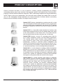
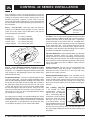
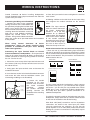
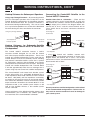
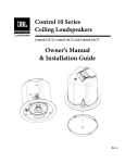
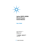
C o ntro l ® 47C / T
C o ntro l ® 47LP
User’s Guide
C o ntro l ® 47H C
Control® 42C
Control® 40CS/T
TABLE OF CONTENTS
Product Description....................................................1
Product Feature Identification...................................2
Control 40 Series Preparation...................................3
Control 40 Series Installation....................................4
Wiring Instructions..................................................5-6
Grilles, Maintenance & Contacting JBL....................7
Specifications.........................................................8-10
JBL Professional Control Contractor 40 Series
PRODUCT DESCRIPTION
Control® Contractor 40 Series is a line of premium, in-ceiling, specialty loudspeakers that combine
outstanding pattern control and consistent coverage with superior sonic performance. Featuring JBL’s
proprietary conical Radiation Boundary Integrator® (RBI™) technology, adapted from the groundbreaking
VerTec® Series of line array loudspeakers, the Control 40 series includes five models. Built on over 60
years of JBL loudspeaker design experience, the Control Contractor 40 Series delivers outstanding
performance and reliability housed in an elegant industrial design.
Control 47C/T features extended bass performance with a wide
120° of coverage that allows fewer speakers to cover a large space.
Ideal for a wide variety of applications, the Control 47C/T is perfect
for settings ranging from restaurant and retail to large casinos and
beyond.
Control 47LP is a low-profile model intended for locations with
limited above-ceiling clearance (only 5.6 inches deep) and is built
on the same platform as the Control 47C/T. The system features
the same great sonic character and wide 120° of coverage.
Control 47HC features a narrow 75° coverage pattern, ideal for
use in highly reverberant spaces and high ceiling applications.
This focused pattern helps minimize sound reflecting off of
room surfaces as well as time arrival anomalies from adjacent
loudspeakers, resulting in improved speech intelligibility. The
Control 47HC features the same sonic character the Control 47C/T
and is ideal for busy transit centers, large convention center spaces
or anywhere requiring a narrow coverage ceiling loudspeaker.
Control 42C is an ultra-compact, in-ceiling satellite loudspeaker
designed for use with the Control 40CS/T in-ceiling subwoofer.
When combined with the Control 40CS/T, the Control 42C offers
an extremely natural sounding and powerful subwoofer-satellite
system that is perfect for applications requiring wide bandwidth
and superior sonic performance with minimal visual impact.
Control 40CS/T is a direct radiating, high impact, 8” subwoofer
with a built-in passive crossover network enabling the Control
40CS/T to be used as part of a subwoofer-satellite system. When
combined with the Control 42C, the Control 40CS/T offers an
extremely natural sounding and powerful subwoofer-satellite
system that is perfect for applications requiring wide bandwidth
and superior sonic performance with minimal visual impact. The
Control 40CS/T can also be used via an active crossover design
with the rest of the Control Contractor in-ceiling line for superior
bass response and can be operated from a 70V / 100V distributed
line or in direct 8Ω mode.
JBL Professional Control Contractor 40 Series 1
PRODUCT FEATURE IDENTIFICATION
(Control 47C/T Shown)
Suspension Tabs
(Control 47C/T & 47HC models only)
Integrated Back Can
Input Connectors
Two-Landing
Dog Ear
(located inside terminal well)
Transformer Tap / Bypass
(located inside waveguide aperture)
Conical RBI® Waveguide
Tuning Port
Tweeter
2 JBL Professional Control Contractor 40 Series
CONTROL 40 SERIES PREPARATION
The installation of the Control Contractor 40 Series inceiling loudspeakers can be accomplished, if necessary,
without requiring access above the ceiling. Bracketry for
use with either suspended ceilings or sheetrock ceilings is
included (see below for additional details on the Control
42C). The loudspeaker is held securely in place via
mounting ears which lock into place. Inputs are attached
to a removable locking connector (included) which can be
prewired before installing the loudspeaker for ultra-fast
snap-on installation.
Available New Construction Brackets
MTC-42NC for the Control 42C
MTC-47NC for the Control 47C/T & Control 47LP
MTC-19NC for the Control 47HC & Control 40 CS/T
2) The optional MUD-RING BRACKET (available options
and listed below) contains a circular offset, forming an
edge guide for sheet rock plastering. The bracket has
wings that attach to the building structure. Sheet rock is
typically precut, then the sheet rock hole can be plastered
(or “mudded”) up to the ring to create a seamless cutout.
The lightweight Control 42C (0.7 kg / 1.6 lbs) includes a
C-ring but does NOT include tile rails. In the event that
tile rails are required, they are available as an optional
accessory (MTC-Rail).
OPTIONAL PRE-INSTALLATION BRACKETS
IN MOST CASES, NO BRACKETS OTHER THAN
THE ONES INCLUDED WITH YOUR SPEAKER ARE
REQUIRED. Everything needed for most installations
of these loudspeakers is provided with your Control
Contractor 40 Series in-ceiling loudspeakers.
Installation into sheet rock (typically gypsum board) can
be facilitated by the use of JBL’s optional preinstallation
brackets before the sheetrock is installed.
The
preinstallation bracket provides a bracket to which wiring
can be tied behind the sheetrock and it can function as
a cutout template when many cutouts are to be made
in a production-line style installation. Two types of preinstallation brackets are available from JBL Professional
as optional accessories:
1) The optional NEW-CONSTRUCTION BRACKETS
(available options and listed below) are made of flat sheet
metal, with wings to attach to the building structure. Holes
are drilled for nails or screws at 16 inches (406 mm) and
24 inches (610 mm) on-center. Additional holes can be
drilled by the installer at other spacings up to a maximum
of 24-3/4 inches (630 mm) apart. Sheet rock installs over
the bracket, and the bracket provides a template for blind
cutout of the hole in the sheet rock. The sheet rock is
typically cut with a router-type cutting tool, using the
bracket ring as a cutout guide.
Optional Mud
Ring Bracket
Available Mud-Ring Brackets
MTC-42MR for the Control 42C
MTC-47MR for the Control 47C/T & Control 47LP
MTC-19MR for the Control 47HC & Control 40 CS/T
USING INCLUDED C-BRACKET WITH SHEETROCK
For many installations, the INCLUDED C-shaped backing
plate provides adequate reinforcement to the ceiling
material, spreading out the clamping force from the tab
clamps.
CUTOUT SIZES
Packaged with the speakers are cardboard cutout templates
for scribing the cutout hole onto your ceiling surface. The
cutout size diameters for the Control Contractor 40 Series
are listed on the following page.
Optional New-Construction
Bracket
JBL Professional Control Contractor 40 Series 3
CONTROL 40 SERIES INSTALLATION
The installation system has been designed so that the
entire installation can be accomplished from beneath the
ceiling, for instances when access above the tile is not
possible or practical. However, in some cases it may be
easier with removable ceiling tiles to access from both the
top and bottom of the ceiling tile during various phases of
the installation.
Step 1 – Cut the Hole. Cutout the hole size either by
tracing the cardboard cutout template or with a circular
cutter set to the cutout sizes listed below and pull the
wiring through the cutout hole.
Control 42C:
Control 47C/T:
Control 47LP:
Control 47HC:
Control 40CS/T:
C-Bracket and Tile
Rail Positioned on
Ceiling Tile
Tile Rails: The tile rails are designed to fit either standard
24-inch wide tiles or 600-mm wide tiles. The tile rail pieces
do NOT physically attach to the T-grid struts. Instead, the
inverted-V shape at the ends of the rails sit OVER the Tgrid strut. During normal operation, the rails are supported
by the edge of the tile. In the unlikely event that the tile
comes out or falls apart, the ends of the support rails are
designed to catch onto the T-grid, providing secure support
to hold the loudspeaker assembly in place.
4.1 inches (104 mm)
11.1 inches (282 mm)
11.1 inches (282 mm)
12.1 inches (307 mm)
12.1 inches (307 mm)
Hole Cutout
Step 2 – Insert Backing Hardware Through the Hole.
Packaged with the speakers are two types of backing
hardware – a C-shaped backing-plate bracket and two tile
rails (except for the lightweight Control 42C which does
NOT include tile rails).
Suspended Ceilings – Insert the C-plate through the hole
cut in the ceiling tile. Place the C-plate around the hole
with the tabs pointing upwards enabling the C-plate to lie
flat on the tile. Insert the tile rails through the cut hole in
the ceiling tile. Snap the two rails into the two tabs in the
C-plate and align the rails so that the ends extend OVER
the T-channel grid on the side of the tile. Secure the rails
onto the C-bracket tabs by inserting a screw through each
tab into the rail. This can all be accomplished from below
the ceiling tile, if necessary.
For safety when installing in suspended ceiling tiles, utilize
all included brackets. Note that the lightweight Control 42C
includes a C-ring only, which may be all that is required for
some applications. If the application calls for tile rails, they
are available separately as part number MTC-RAIL.
4 JBL Professional Control Contractor 40 Series
Vibration Reduction: These loudspeakers can generate
substantial vibration, which can cause buzzing of the
ceiling materials or structure. Depending on the character
of the ceiling tile and structure, the installer might need to
place neoprene or other dampening material under the tile
rails or the edges of the tiles to address rattles from the
ceiling materials.
Cutout Placement: The tile rails are pre-punched with
attachment holes along their length. Placement is not
limited to the center of the tile as is the case with many
other tile rail support systems.
Non-Suspended Ceiling Types – The C-bracket can be
optionally used by itself to shore up the ceiling material
and to spread out the clamping force from the tab clamps.
Insert the C-plate through the cut hole in the ceiling and
place it on the back side of the hole before inserting the
speaker.
Two Landing Dog-Ears
– All Control 40 Series Second Landing
Loudspeakers (except the
Control 42C) are equipped
with a two-landing dog ear
suspension system enabling
them to be used with ceiling
tiles that are up to 70 mm
(2.75 inches) thick. If using
Control 40 loudspeakers with
ceiling tiles that are greater
than 54 mm (2.125 inches) thick, start with the dog ear in
the second (top) landing to ensure clearance and ease of
installation.
WIRING INSTRUCTIONS
Control Contractor 40 Series in-ceiling loudspeakers
include Euroblock locking input connectors that allow the
system to be “pre-wired”.
Connecting the Wiring to the Euroblock
-- Connect the wiring to the removable
locking connector that is INCLUDED with
the speaker by stripping the insulation back
about 5 mm (about 3/16 inch), inserting
+
the bare end of wire into the connector and
screwing down the hold-down screw until
tight using a small flatblade screwdriver.
Tighten any unused screws to avoid 2-pin Connector
vibration. Using terminal block connectors
allows the system to be pre-wired before final installation
of the product.
When wiring Control Contractor 40 Series
loudspeakers, always use proper electrical wiring
practices in accordance with your area’s building
codes and regulations.
Connecting the Input Terminal Block on Control
Contractor 40 Series Loudspeakers -- The input terminal
cover on all Control Contractor 40 Series are fitted with a
conduit connector for securing wiring conduit to and from
the unit. To wire the unit:
1. Loosen the screw on top of the input terminal cover and
then remove (and save) the input terminal cover screw on
the side of the can.
2. Swing open the input terminal cover and remove the
euroblock connector.
+ + IN
IN
Loop Loop
Thru Thru
3. Insert the bare ends of wire into the Euroblock connector
and secure the wires with the hold-down screws. (see
Connecting the Wiring to the Euroblock)
+
-
Euroblock
Connector
Conduit
Connector
4. Loosen the conduit
connector on the input
terminal cover and insert
the
wired
euroblock
connector
through
the conduit connector
+ Connect
+
opening.
the
Sat 3
Sat 4
euroblock to the matching
receptacle.
+
-
Sat 1
+
IN
-
IN
+
-
Sat 2
+
-
Loop Loop
Thru Thru
5. Close the input terminal cover and tighten the terminal
cover screws.
6. Allowing sufficient strain relief slack for the input wiring
and re-tighten the conduit connector on the terminal
cover.
NOTE: The input terminal
cover on Control Contractor
40 Series loudspeakers
includes a .75 in (19 mm)
knockout for an additional
conduit clamp. This knockout
point can be used in addition
to the conduit connector
located on the top of the can
and is useful for wiring loopthru runs or when access is
limited on the top of the can.
-
+
IN
IN
+
Knockout
-
Loop Loop
Thru Thru
Guide to Connection Pins on Control 40 Loudspeakers
-- There are two (2) removable locking input connectors
with two (2) terminals on each for the Control 42C, Control
47C/T, Control 47LP and Control 47HC and six (6) terminals
on the Control 40CS/T. The pin functions are listed on the
label located on the can.
Control 42C:
+
IN
-
IN
Control 40CS/T:
+
+
-
-
+
Sat 3
Loop Loop
Thru Thru
-
Sat 4
+
IN
+
Control 47C/T, LP & HC:
-
+
Sat 1
-
Sat 2
+
+
+
-
IN
IN
+
-
IN
-
IN
+
-
Loop Loop
Thru Thru
Loop Loop
Thru Thru
+
-
+
-
Sat 3
Sat 4
To wire Control 40 Series loudspeakers
simply connect
the positive wire to the “+” pin and connect the negative
wire to the “-” pin. The “IN” pins
- paralled
+ - to the “LOOP
+ are
Sat 1
Sat 2the loudspeaker.
THRU” pins (+ and - respectively)
inside
The “Loop Thru” pins allow a parallel connection to an
additional loudspeaker.
+ + IN
IN
Loop Loop
Thru Thru
To select the operating mode or desired output tap of the
loudspeaker, simply rotate the tap selector switch located
on the front of the baffle to the desired setting.
Note: Both 70V/(100V) connections and low impedance
connections are made via the same input pins. When
using the transformer tap selections, be sure that the
power amplifier is set on 70V/(100V) mode and the leads
feeding the system are connected to 70V/(100V) outputs
on the amplifier.
JBL Professional Control Contractor 40 Series 5
Loo
Thru
WIRING INSTRUCTIONS, CON’T
Hookup Schemes for Subsequent Speakers
Using Loop-Through Terminals -- By connecting the wire
pair of a subsequent speakers to the “Loop Thru” on the
Control 40 Series Loudspeakers all subsequent speakers
will be disconnected when this speaker’s connector is
disconnected during troubleshooting. This can be useful
as a way to isolate problems to a section of the distributed
line while leaving the wires attached to the connector.
Using Loop Through Terminals
+
IN
+
-
Satellite Home Run to Subwoofer -- There are four
satellite output pins on the Control 40CS/T. If using only
two Control 42C satellites, connect each loudspeaker to
a single output pin as shown in the diagram below; one
Control 42C in “Sat 1” and the second Control 42C to
“Sat 2” ONLY. “Sat 3” and “Sat 4” connectors should not
be used.
Control 40CS/T
Connecting two
Control 42Cs
-
IN
Connecting the Control42C Satellite to the
Control 40CS/T Subwoofer
-
+
+
-
From Amplifier or
Previous Speaker
Loop Loop
Thru Thru
Sat 3
+
-
+
To Subsequent
Speakers
Sat 1
To Control 42C
Hookup Schemes for Subwoofer-Satellite
Systems Using Control 40CS/T & Control 42C
Loudspeakers
The Control 40CS/T subwoofer features a built-in
crossover network designed for use with the Control
42C Ultra-Compact Satellite loudspeakers. Two or four
Control 42C satellite loudspeakers can be used with the
Control 40CS/T to create an extremely natural sounding
and powerful subwoofer-satellite system that is perfect
for applications requiring wide bandwidth and superior
sonic performance with minimal visual impact. Using four
Control 42C satellite loudspeakers with a Control 40CS/
+
T will offer approximately twice the area coverage than a
system using only two Control 42C satellite loudspeakers.
-
+
+
IN
IN
-
+
Sat 4
-
+
Sat 2
-
+
Loop Loop
Thru Thru
-
-
Sat 3
+
-
Sat 1
+
+
+
+
IN
-
IN
+
-
Sat 4
+
To
Control 42C
-
Sat 2
+
-
+
Loop Loop
Thru Thru
+
-
From Amplifier
+
-
If using four Control 42C satellites, connect each
loudspeaker to a single output connector as shown in the
diagram below, one Control 42C in “Sat 1”, the second
Control 42C to “Sat 2”, the third Control 42C to “Sat 3”, the
fourth Control 42C to “Sat 4.”
Connecting two+ Control 42Cs Sat 3
+
-
+
+
+
Sat 1
-
Sat 4
-
Sat 2
Control 40CS/T
+
+
-
Sat 3
+
-
Sat 4
-
+
+ + + + The Control 40CS/T and Control 42C Sub-Sat system
To Control 42C
+
To Control 42C
can be driven either via a 70V/(100V) distributed line or
+
+ + in low impedance direct mode. Like the rest of the Control
+
40 Series, 70V/(100V) and low impedance connections +
+
are made via the same input pins on the Control 40CS/T.
The Control 42C Satellites are then connected to satellite +
output connectors located on the Control 40CS/T. In low
impedance mode, a two satellite system creates an 8Ω
From Amplifier
load on your amplifier whereas, a four satellite system
creates a 4Ω load.
Use only two or four satellite loudspeakers as described
in the recommended configurations. Failure to do so
Choose whichever of the following hookup patterns best may result in uneven sound levels and / or damage to
accommodates your installation. All satellite speakers your sound system.
must terminate at the Control 40CS/T subwoofer.
IN
IN
Loop Loop
Thru Thru
Sat 1
IN
6 JBL Professional Control Contractor 40 Series
IN
Sat 2
Loop Loop
Thru Thru
PAINTING & CONTACTING JBL
PAINTING CONTROL
LOUDSPEAKERS
CONTRACTOR
40
SERIES
The trim ring and grille of Control Contractor 40 Series
loudspeakers can be painted to match almost any decor.
The speaker’s polystyrene rim accepts almost any type of
latex or oil based paint.
For best results,
recommended:
the
following
procedure
is
1. Clean the rim and grille with a light solvent such as
mineral spirits by rubbing the item with a lightly dampened
cloth. Do not use abrasives such as sandpaper or steel
wool, nor should you use gasoline, kerosene, acetone,
MEK, paint thinner, harsh detergents or other chemicals.
Use of these cleaners may result in permanent damage to
the enclosure.
2. After cleaning, apply two or more thin coats of either
latex or oil-based paints. Latex paint will adhere better if an
oil-based primer is used first. Application can be made by
rolling, brushing or spraying.
Painting the Speaker Along With the Ceiling – Insert
the clear plastic paint shield into the front of the speaker
to mask the drivers and internal baffle, paint the speaker,
then remove the shield.
CONTACTING JBL PROFESSIONAL
These products are designed and backed by JBL
Professional, the world leader in professional sound
reinforcement. For complete warranty information, to
order replacement parts or to ask for clarifications to this
manual, contact JBL Professional.
Within the United States:
Applications Department, JBL Professional
8500 Balboa Blvd., PO Box 2200
Northridge, CA 91329 USA
In the USA you may call Monday through Friday 8:00am to
5:00pm Pacific Coast Time (800) 894-8850.
Outside the USA:
Contact the JBL Professional Distributor in your country.
A list of JBL Professional Distributors and US Service
Centers can be obtained from the JBL Professional website
at: www.jblpro.com
Painting the Grille – Painting the grille requires removal of
the logo and the internal grille cloth before spray painting.
Multiple sprayed coats using thinned paint is recommended
to avoid clogging the grille holes. If the grille is rolled or
brush painted, the mesh may become clogged with paint
and poor sound quality may result. Replace the internal
grille cloth and JBL logo.
Maintenance -- No maintenance is required when
assembled in accordance with the instructions and wiring
guidelines described in this manual.
JBL Professional Control Contractor 40 Series 7
SPECIFICATIONS
Control 47C/T:
Frequency Range (-10 dB)1:
Frequency Response (± 3 dB) 1:
Power Capacity 2:
Nominal Sensitivity (2.83V/1m)1:
Nominal Coverage Angle 3:
Directivity Factor (Q)3:
Directivity Index (DI)3:
Rated Maximum SPL:
Rated Impedance:
Transformer Taps:
55 Hz - 20 kHz
75 Hz - 17 kHz
150 Watts Continuous Program Power
75 Watts Continuous Pink Noise
91 dB
120° conical coverage
6.5
7.9dB
110 dB @ 1 m (3.3 ft) average, 116 dB peak
8 Ω (in bypass mode)
60W 30W, 15W, (& 7.5W @ 70V)
LF Driver: 165mm (6.5 in) with polypropylene cone, butyl rubber surround, copper-clad coil, vented aluminum former.
HF Driver: 25mm (1 in) soft dome w/ dampening, ferrofluid-cooled.
Input Connectors:
Knockouts:
Safety Agency:
Dimensions:
Cutout Size:
Ceiling Thickness Range:
Net Weight:
Included Accessories: Two removeable locking 2-pin connectors with screw-down terminals.
Max wire 12 AWG (2.5 mm). Key: 1) + in, 2) - in, A) + loop thru, B) - loop thru
Two (top and side)
Designed for the requirements of use in air handling spaces per UL1480,
UL2043, NFPA90, NFPA70A, and in accordance with the requirements of IEC60849/EN60849
Ø 305 mm (12.0 in) diameter x 359 mm (10.2 in) mounting depth
282 mm (11.1 in)
Accommodates tiles / drywall up to 70 mm (2.75 inches) thick
5 kg (11 lbs)
press-in grille, C-ring support backing plate, 2 tile support rails, knockout strain relief,
cutout template, paint shield
Control 47LP:
Frequency Range (-10 dB)1:
Frequency Response (± 3 dB) 1:
Power Capacity 2:
Nominal Sensitivity (2.83V/1m)1:
Nominal Coverage Angle 3:
Directivity Factor (Q)3:
Directivity Index (DI)3:
Rated Maximum SPL:
Rated Impedance:
Transformer Taps:
68 Hz - 20 kHz
100 Hz - 17 kHz
150 Watts Continuous Program Power
75 Watts Continuous Pink Noise
91 dB
120° conical coverage
6.7
7.9dB
110 dB @ 1 m (3.3 ft) average, 116 dB peak
8 Ω (in bypass mode)
60W 30W, 15W, (& 7.5W @ 70V)
LF Driver: 165mm (6.5 in) with polypropylene cone, butyl rubber surround, copper-clad coil, vented aluminum former.
HF Driver: 25mm (1 in) soft dome w/ dampening, ferrofluid-cooled.
Input Connectors:
Knockouts:
Safety Agency:
Dimensions:
Cutout Size:
Ceiling Thickness Range:
Net Weight:
Included Accessories: Two removeable locking 2-pin connectors with screw-down terminals.
Max wire 12 AWG (2.5 mm). Key: 1) + in, 2) - in, A) + loop thru, B) - loop thru
Two (top and side)
Designed for the requirements of use in air handling spaces per UL1480,
UL2043, NFPA90, NFPA70A, and in accordance with the requirements of IEC60849/EN60849
Ø 305 mm (12.0 in) diameter x 142 mm (5.6 in) mounting depth
282 mm (11.1 in)
Accommodates tiles / drywall up to 70 mm (2.75 inches) thick
4.3 kg (9.5 lbs)
press-in grille, C-ring support backing plate, 2 tile support rails, knockout strain relief,
cutout template, paint shield
8 JBL Professional Control Contractor 40 Series
SPECIFICATIONS
Control 47HC:
Frequency Range (-10 dB)1:
Frequency Response (± 3 dB) 1:
Power Capacity 2:
Nominal Sensitivity (2.83V/1m)1:
Nominal Coverage Angle 3:
Directivity Factor (Q)3:
Directivity Index (DI)3:
Rated Maximum SPL:
Rated Impedance:
Transformer Taps:
55 Hz - 17 kHz
70 Hz - 14 kHz
150 Watts Continuous Program Power
75 Watts Continuous Pink Noise
93 dB
75° conical coverage
10.2
12.0dB
112 dB @ 1 m (3.3 ft) average, 114 dB peak
8Ω (in bypass mode)
60W 30W, 15W, (& 7.5W @ 70V)
LF Driver: 165mm (6.5 in) with polypropylene cone, butyl rubber surround, copper-clad coil, vented aluminum former.
HF Driver: 25mm (1 in) soft dome w/ dampening, ferrofluid-cooled.
Input Connectors:
Knockouts:
Safety Agency:
Dimensions:
Cutout Size:
Ceiling Thickness Range:
Net Weight:
Included Accessories: Two removeable locking 2-pin connectors with screw-down terminals.
Max wire 12 AWG (2.5 mm). Key: 1) + in, 2) - in, A) + loop thru, B) - loop thru
Two (top and side)
Designed for the requirements of use in air handling spaces per UL1480,
UL2043, NFPA90, NFPA70A, and in accordance with the requirements of IEC60849/EN60849
Ø 346 mm (13.6 in) diameter x 353 mm (13.9 in) mounting depth
307 mm (12.1 in)
Accommodates tiles / drywall up to 70 mm (2.75 inches) thick
6.4 kg (14 lbs)
press-in grille, C-ring support backing plate, 2 tile support rails, knockout strain relief,
cutout template, paint shield
Control 42C:
Frequency Range (-10 dB)1:
Frequency Response (± 3 dB) 1:
Power Capacity 2:
Nominal Sensitivity (2.83V/1m)1:
Nominal Coverage Angle 3:
Directivity Factor (Q) 3:
Directivity Index (DI) 3:
Rated Maximum SPL:
Rated Impedance:
140 Hz - 20 kHz
180 Hz - 17 kHz
30 Watts Continuous Program Power
15 Watts Continuous Pink Noise
82 dB
160° conical coverage
6.6
6.8dB
94 dB @ 1 m (3.3 ft) average, 100 dB peak
16Ω
Driver: 60mm (2.5 in) mid-high
Input Connectors:
Knockouts:
Safety Agency:
Dimensions:
Cutout Size:
Ceiling Thickness Range:
Net Weight:
Included Accessories: Two removeable locking 2-pin connectors with screw-down terminals.
Max wire 12 AWG (2.5 mm). Key: 1) + in, 2) - in, A) + loop thru, B) - loop thru
Two (top and side)
Designed for the requirements of use in air handling spaces per UL1480,
UL2043, NFPA90, NFPA70A, and in accordance with the requirements of IEC60849/EN60849
Ø 127 mm (5.0 in) diameter x 97 mm (3.8 in) mounting depth
104 mm (4.1 in)
Accommodates tiles / drywall up to 27 mm (1.06 inches) thick
0.7 kg (1.6 lbs)
press-in grille, C-ring support backing plate, knockout strain relief, cutout template, paint shield
JBL Professional Control Contractor 40 Series 9
SPECIFICATIONS
Control 40CS/T:
Frequency Range (-10 dB)1:
Frequency Response (± 3 dB) 1:
Power Capacity 2:
Nominal Sensitivity (2.83V/1m)1:
Rated Maximum SPL:
Rated Impedance:
Transformer Taps:
30 Hz - 300 Hz
50 Hz - 180 Hz
200 Watts Continuous Program Power
100 Watts Continuous Pink Noise
95 dB (near corner), 89 dB (center of ceiling)
109 dB @ 1 m (3.3 ft) average, 115 dB peak (center of ceiling)
8 Ω (in bypass mode)
80W 40W, 20W, (& 10W @ 70V)
Driver: 200mm (8 in) with polypropylene cone, butyl rubber surround, copper-clad coil, vented aluminum former.
Input Connectors:
Knockouts:
Safety Agency:
Dimensions:
Cutout Size:
Ceiling Thickness Range:
Net Weight:
Included Accessories: Six removeable locking 2-pin connectors with screw-down terminals.
Max wire 12 AWG (2.5 mm). Key: 1) + in, 2) - in, A) + loop thru, B) - loop thru
Satellite Key: Sat 1 - Satellite 1, Sat 2 - Satellite 2, Sat 3 - Satellite 3, Sat 4 - Satellite 4,
Two (top and side)
Designed for the requirements of use in air handling spaces per UL1480,
UL2043, NFPA90, NFPA70A, and in accordance with the requirements of IEC60849/EN60849
Ø 346 mm (13.6 in) diameter x 346 mm (13.6 in) mounting depth
307 mm (12.1 in)
Accommodates tiles / drywall up to 70 mm (2.75 inches) thick
8.1 kg (17.9 lbs)
press-in grille, C-ring support backing plate, 2 tile support rails, knockout strain relief,
cutout template, paint shield
Optional Accessories :MTC-Rail Tile Rails, for use with Control 42C
MTC-42NC New Construction Bracket, for use with Control 42C
MTC-42MR Mud Ring Construction Bracket, for use with Control 42C
MTC-47NC New Construction Bracket, for use with Control 47C/T & Control 47LP
MTC-47MR Mud Ring Construction Bracket, for use with Control 47C/T & Control 47LP
MTC-19NC New Construction Bracket, for use with Control 47HC & Control 40CS/T
MTC-19MR Mud Ring Construction Bracket, for use with Control 47HC & Control 40CS/T
1
2
3
In half space (in ceiling)
IEC standard, full bandwidth pink noise with 6 dB crest factor
Average 1 kHz to 16 kHz
JBL continually engages in research related to product improvement. Changes introduced into existing products without notice are an expression of that philosophy.
440921-004
09/08
8500 Balboa Boulevard
Northridge, CA 91329 USA
Visit us online at www.jblpro.com