1
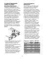
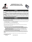
1. Introduction
either subwoofer or component
speakers in a bi-amplified system,
or conventional full-range speakers
in simpler systems.
The GTS300 and 600 also include
preamp-level outputs which can
provide either full-range, high-pass
or low-pass signal to drive
additional amplifiers. This lets you
build systems of virtually any
design without requiring a
separate electronic crossover.
Thanks for purchasing your new
GT series automotive amplifier.
The GT series amplifier you have
chosen includes many unique
features to enhance its performance and utility. The power amplifier circuitry is a fully discrete
design notable for its low distortion and unusually clean and
clear sound quality. Your GT series
amplifier will easily connect to
virtually any car audio system,
whether it is factory installed or
one purchased separately.
In addition to conventional
preamplevel inputs, this model
features JBL’s Universal Interface
design, which facilitates simple
connection to factory radios with
the low distortion that is usually
only associated with preamp level
connection. With Universal Interface, a factory radio can be used
either as the main music source or
combined with a CD player or
changer, which includes volume
control capability, simultaneously
connected to the amplifier. By
providing this two-unit direct
connection, Universal Interface
circuitry eliminates the need for an
FM modulator to interface a CD
player to factory radios, improving
the fidelity of digital playback.
In addition, when using a highpowered (BTL) radio through the
speaker-level inputs, Common
Sense turn-on circuitry senses the
common-mode voltage present on
the radio’s speaker wires, turning
the amplifier on without an
additional “remote” wire.
Also, the built-in active crossover
provides either full-range, highpass or low-pass operation. This
lets your GT series amplifier power
1.2 About Installation
Although the GTS300 and GTS600
are designed to make installation
as easy as possible, they are
sophisticated products that require
proper installation to realize their
full performance potential.
If you feel you do not have the
necessary knowledge and skills we
strongly recommend that the
installation be done by your
authorized JBL dealer.
If you choose to install the GTS300
or GTS600 yourself read all of the
information in this manual
before you start the installation.
Pay particular attention to the
safety precautions and notes.
2. Installation and Use
Refer to the “Crossover Frequency
Adjustments” and “Speaker Level
Input Impedance Adjustments”
sections of this manual to see if
you will need to make alterations
to their factory settings. If you are
not using the built-in crossover, or
the speaker level inputs, you may
skip this step.
1. Disconnect the negative cable
from the battery. Note: If the
vehicle’s radio features a code
type security system, make
certain you know the code
1
before disconnecting the
battery!
2. Run a minimum AWG #8
power cable complete with a
40 amp fuse (not included) for
the GTS300 or an AWG #6 or
AWG #4 cable with an 80 amp
fuse for the GTS600 directly
from the positive + 12V battery
terminal to the disired
amplifier location. Keep the
fuse to within 6” of the battery
terminal, and before the wire
runs through any metal
partition.
Note: All wiring connections
should be made either by
soldering with heatshrink tubing
insulation or with high quality
crimp type insulated connectors
installed with a professional type,
articulated crimping tool.
Soldering crimptype terminals is
recommended for additional
security. Never use wire-nuts,
insulation-displacement
connectors (i.e. ScotchLok type),
or “twist and tape” connections.
Do not use electrical tape; it will
loosen with age and extreme
temperatures.
3. Mount amplifier in the desired
location using four screws.
4. Connect power wiring as
shown i the Wiring Diagram.
5. Connect the outputs from the
head unit to the appropriate
inputs of the amplifier
according to the Wiring
Diagram with either high
quality low-level signal cables
with RCA plugs, with the
supplied speaker-level input
connector, or both.
6. Connect the speakers to the
amplifier according to the
wiring diagram.
7. Turn the input gain adjustment
to the 1/4 position.
8. Set the crossover switches as
desired.
9. Set the input mode switch to
stereo, left + right or right
input only operation.
10. Set the bass boost switch to
the desired position.
11. Reconnect the negative
battery cable.
12. Turn on the signal source at a
low volume level and check
for the correct output from
each speaker.
13. Adjust the amplifier gain
control using the procedure
described in the “Adjusting
the Gain” section.
2.2 Controls and Connectors
1. Preamp-Level Input Connector –
Use these connectores for line
(preamp) level input to the
amplifier.
2. Preamp-Level Output Connector
– Use these outputs to send the
signal to additional amplifiers.
3. Speaker-Level Input Connector –
Use this connector for speaker
level input signals. A wire harness
is supplied for use with this
connector. This input also includes
JBL’s Common Sense input
circuitry which turns the amplifier
on as soon as the high powered
head unit connected to this input
is turned on.
4. Speaker Output Connector –
Connect speaker wiring to this
connector. See “Wiring” directions
for more information.
5., 6., 7., 8., Power Connector –
Connection for power wires #A.
See “Wiring” directions for
information on proper
connections.
2
9. Fuse – 40 Amp ATC type fuse for
the GTS300 and two 40 amp fuses
for the GTS600.
10. Gain Control – Use this control
to adjust the input sensitivity of
the amplifier. See the “Adjusting
the Gain” section for tips on
proper setup.
11. Preamp-Output Crossover
Switch – This switch controls the
built-in crossover that is directed
to the preamp-output connectors.
Set the switch to “Flat” for full
band operation. Set this switch to
“Low-Pass” to activate the lowpass filter on the preamp output
(for subwoofer use). Set the switch
to “High-Pass” to activate the
high-pass filter for use with
satellite speakers.
12. Speaker Output Crossover
Switch – This switch controls the
built-in crossover that is connected
to the power amplifier circuitry.
Set the switch to “Flat” for full
band operation. Set this switch to
“Low Pass” to activate the low
PREAMP
OUTPUT
LINE
INPUT
L
R
R
SPEAKER
OUTPUT
SPEAKER LEVEL
INPUT
+
+
R
L
_
_
POWER
FUSE
40A
+
REM IN
+
R
L
_
_
40A
L
pass filter on the amplifier (for
subwoofer use). Set the switch to
“High Pass” to activate the high
pass filter for use with satellite
speakers.
13. Input Mode Selector – This
switch is used to set the input
mode for both preamp and
speaker-level inputs.
Set this switch to Stereo for
normal operation using both left
and right inputs. Set this switch to
R to drive both the left and right
output channels with only a single
input on the right channel. Set this
switch to “L+R” to sum the left
and right inputs for a mono output
on both amplifier channels.
Power Indicator LED (on chassis
top) – LED steadily illuminates for
normal operation. LED blinks
when protection circuitry or
muting is engaged.
14. Bass Boost Switch – This
activates a built-in Bass Boost
circuit used to increase low-bass
output.
BATT(+)
REM OUT
GND
BRIDGED
➀ Preamp Level RCA Inputs
➄ Remote Turn On Output
➁ Preamp Level RCA Outputs
➅ Battery Ground
➂ High Level Speaker Inputs
➆ Battery (+12v) In
➃ Speaker Outputs
Power
Connector
➇ Remote Turn On Input
➈ Fuse
BASS BOOST
OFF
SPEAKER OUTPUT
CROSSOVER
INPUT MODE
ON
R
L+R
STEREO
FLAT
PREAMP OUTPUT
CROSSOVER
HIGH PASS
LOW PASS
FLAT
NOM
HIGH PASS
LOW PASS
MIN
MAX
GAIN
➉ Gain Control
Preamp Crossover Frequency Selector
Amplifier Crossover Frequency Selector
Input Mode Selector
Bass Boost
3
3. System Design Using the
GTS300 or GTS600:
3.2 Signal Sources
The low level preamp outputs of
any radio/tape deck, CD player or
preamp/equalizer so equipped can
drive the GTS300 or GTS600. The
gain controls of the GTS300 or
GTS600 are used to match the
amplifier’s input sensitivity to the
output voltage of the source. This
matching is important to keep
noise low and is explained in the
“Adjusting the Gain” section of
this manual.
Thanks to Universal Interface
Circuitry, the GTS300 or GTS600
can also be connected to power
amplifiers, radios or equalizers
that are equipped with only
speaker outputs by connecting
them through the speaker level
input connector. Inside the GTS300
or GTS600, the speaker-level and
preamp-level inputs are connected
through a mixing circuit, which
allows them to be used
simultaneously. Therefore a low
level source, such as a CD player
equippe with a volume control
may be connected to the preamplevel inputs at the same time as a
powered radio/tape unit is
connected to the speaker-level
inputs. This provides a higher
performance alternative to an FM
Modulator connection when you
wish to add CD capability to a
factory casette stereo. Switching
from one source to the other is as
simple as turning the desired
source on and turning the
undesired one off – no additional
switches or relay connections are
needed.
3.1 Speaker Requirements
When used in the non-bridged
mode the GTS300 or GTS600 can
easily drive 2 ohm speaker loads.
When only one speaker is
connected to each channel,
virtually any conventional speaker
may be used.
When the GTS300 or GTS600 is in
bridged mode, the combined
impedance of the speaker (or
speakers) connected to the bridged
channel should be at least 4 ohms.
Sustained operation of the GTS300
or GTS600 in bridged mode with
less than 4 ohms will likely cause
overheating.
The GTS300 or GTS600 must not
be used with speakers that have
either one of their input terminals
wired to the frame of the speaker
or to the chassis of the vehicle.
Parallel Wiring
(+)
2 Ohms
Nominal
Impedance
4 Ohms
4 Ohms
(–)
Series Wiring
(+)
4 Ohms
8 Ohms
Nominal
Impedance
(–)
4. Wiring
4 Ohms
Proper wiring of the GTS300 or
GTS600 and the associated
4
components is extremely
important for proper performance
and long term reliability.
All wiring connections should be
made either by soldering with
heatshrink tubing insulation or
with high quality crimp type
insulated connectors installed with
a good crimping tool. Soldering
crimp connections is recommended to further enhance
connection reliability. Never use
wire-nuts, insulation-displacement
connectors (i.e. ScotchLok type), or
“twist and tape” connections. Do
not use electrical tape; it will
loosen with age and extreme
temperatures. Never leave bare
wire exposed.
Route the wiring through the car
carefully. Do not allow wires to lay
against sharp sheet metal edges or
any other surfaces that might wear
away or cut through the insulation
of the wire. Use insulated strain
reliefs, rubber grommets and
plastic tubing to protect the wires
whenever they are run through
sheet metal panels or are placed
where they might be pulled or
damaged.
Cassette/CD Tuner
Speaker Level Output Connection
(Use only when line level ouput
is not available)
CD Player
or Changer
Cassette/CD Tuner
Antenna Input
Power
Antenna
Amplifier
Power
Connection
POWER
Fuse
Red - Main +12V
Yellow - Back Up Power
Remote On/Off
Black - Power Ground
Remote Antenna
Blue (Blue/White)
Power
Supply
Fuse
Cassette/CD Preamp Output
Power
Antenna
Relay
Antenna
Motor
CD Input
Cassette/Receiver
Power Supply
Wires
MA
DE
IN THE
US
A
Amplifier
Speaker
Level
Input
Line
Input
Blue w/White Stripe - Remote On/Off
Amplifier
Speaker
Output
Connection
Speakers
+
–
Ignition Switch
GTS300 – 40 Amp
GTS600 – 80 Amp
(Not Included)
Fuse
–
Main +12V
+
Vehicle Battery
Power Ground
Chassis Ground
5
+
5. Internal Adjustments
Crossover Frequency
Adjustments
Speaker-Level Input
Impedance Adjustments
The GTS300 and GTS600 amplifiers include built-in frequency
selectable crossovers. One
crossover is connected in series
with the amplifier circuitry and the
other crossover is connected to the
preamp level output jacks. These
crossovers can be set in either the
“flat” (full bandwidth operation),
Low Pass (Subwoofer operation),
or High Pass (satellite operation).
• The crossover frequencies are
set by “chips” inside the
amplifier. These “chips” are
simply a set of resistors,
connected across the pins and
molded into a single package.
The crossover frequencies may
be changed to any value desired
by changing the resistor
network. JBL has “chips”
available in the popular values
listed in the table below. If none
of these suit your system, you
may pruchase compatible
resistor networks from a local
electronics store, or you may
build you own custom values
from discrete resistors mounted
on a 14-pin “DIP Header” using
the instructions which follow.
The speaker level inputs of the
GTS300 and GTS600 come factory
set with 100K ohm input impedance. This will provide the lowest
distortion operation from the
speaker outputs of most modern
head units by reducing the power
the amplifier in the head unit must
deliver to practically nothing.
On some older, or lowerpriced
head units, this load will not
facilitate proper fader operation.
To provide for this, we have
provided the ability to change the
input impedance of the speakerlevel inputs to 15 ohms. This is
accomplished by connecting the
jumpers as shown in the diagram
below.
JUMPER SELECTOR
SELECT 100K OR 15 OHMS
ED
NC
LA TS
BA INPU
R
HT
RIG IN
Z EL
S
M
OH
BR
IDG
M
OH
L
ED
LE
KER
EA UT
SP INP
+
R
–
+
R
–
VEL
15
R
BA
40
K
MP
EA
PR TPUT
OU
100
L
T
LEF IN
Z EL
S
ER
CE
EAK
SP PUT EDANTOR
IN P EC
IM EL
S
15
E
LINUT
INP
K
100
+
L
–
SE
FU
A
40
GN
D
M
RE T
OU
• If the head unit has 4 channels of
builtin amplification and/or an
electronic fader control, you
should leave the jumpers in the
factory set position.
• If the head unit has 2 channels of
amplification, with a speakerlevel fader, the jumpers should
be set to the 15-ohm position.
This will always be a rotary-type
control, not one controlled by
elecronic pushbuttons.
Frequency Resistor JBL Part
Value
Number
50 Hz
80 Hz
120 Hz
200 Hz
250 Hz
500 Hz
2.5 Hz
5 Hz
6
47 K
33 K
20 K
12 K
10 K
4.7 K
1K
470
GTM 50
GTM 80
GTM 120
GTM 200
GTM 250
GTM 500
GTM 2500
GTM 5000
Regardless of whether you build
or buy it, the necessary resistor
network has the following
configuration:
• To build “chips” from discrete
resistors, solder the resistores to
a standard 14-pin “DIP Head”
according to the diagram. If a
DIP Header is not available, you
may bend the leads of 1/4 watt
resistors 90 degrees, trim them
to 3mm-length, and insert them
directly into the chip sockets.
Custom “Chip” Construction
To change the crossover frequency
change the resistor network as
follows:
1. Remove the screws from the
bottom panel as shown below.
2. Select which resistor module,
high pass or low pass, that you
wish to change.
3. A chip puller, wich can be
obtained from any electronics
store, is used to remove the
resistor chip. Pull the resistor
chip from the socket as shown
in figur below.
• Each resistor in the package has
the same value.
• If you kvow the crossover
frequency you want, you can
calculate the resistor value
necessary by solving the
following equation:
HIG
H
FR FILT PASS
SE EQUEER
C1
LE
3
MO CT NCY
DU ION
LE
C1
0
LO
W
FR FILT PASS
SE EQUEER
LE
MO CT NCY
DU ION
LE
CR
OSS
OVE
R
NO JB
RT L
JB HR INC.
PC L GTIDGE
00 S6 , C
RE 1088 00 A
V A 00
Resistor
2,500,000
Value
=
Crossover
in Ohms
Frequency in Hz
• Use the following equation if
you have a resistor pack of a
known value, and want to find
it’s crossover frequency:
4. Place the new module in the
socket making sure all pins are
lined up with the socket holes.
Press the module firmly into the
socket.
5. Replace the bottom lid.
Crossover
2,500,000
Frequency =
Crossover
in Hz
Resistor Value in Ohms
7
6. Input Gain Adjustment
until the system plays as loud as
necessary ot when the first signs of
distortion are heard.
Before operating the GTS300 or
GTS600, recheck all wiring
connections to make sure they are
correct and secure. Be sure that a
fuse (40 amp for GTS300 and two
40 amp fuses for the GTS600, not
included) is installed in the +12V
line near the battery. Reconnect the
negative ground (-) terminal of the
battery. Make sure that the input
mode selector, speaker output
crossover frequency modules, and
preamp output crossover switch
are properly set.
BEST-Vertical Mounting
AIR FLOW
MA
Adjusting the Gain
• The setting of the gain control on
the GTS300 and GTS600 is
important to ensure proper
performance, low noise levels,
and maximum reliability in the
system.
Using a high signal level from
the source and a low gain setting
on the amplifier will help keep
backgroune noise levels in the
system low.
• To adjust a system using a single
amplifier, start with the amplifier
gain controls fully
counterclockwise.
DE
IN THE
M
E
A D
A
E
A D
M
US
I N
I N
T H
E
T H
E
GOOD-Horizontal Mounting
Set all Bass/Treble or equalizer
controls to their centered or
bypassed positions. While
listening carefully to the system
output, adjust the volume control
of the radio/tape deck to the point
where you first begin to hear
audible distortion. Reduce the
level just to the point where the
distortion goes away.
If this setting does not provide
adequate volume levels, gradually
increase (turn clockwise) the gain
control on the GTS300 ot GTS600
AIR FLOW
NEVER-Mount Upside Down
8
7. Typical Applications
The following diagrams show the
most common basic system
configurations of the GTS300 and
GTS600. A combination of one or
more of these “building blocks”
may be combined to form elaborate system designs.
9
Application 1Application 1
Stereo
or Subwoofer
Operation
Stereo Full-Range
orFull-Range
Subwoofer
Operation
Preamp or
L Speaker-Level R
Input
Full-Range Operation
Stereo
USA
Flat
I N T HE
Input Mode
Switch
DE
MA
Speaker Output
Crossover
Switch
Subwoofer Operation
GTS300/600
Speaker Output
Crossover
Switch
Input Mode
Switch
Low Pass
Stereo
L– L+
–
R– R+
+
–
2 or 4-Ohm
Full-Range
+ Speakers or
Subwoofers
Main speakers are driven by head unit or
additional amplifier.
Application Application
2
2
Bridge-Mode Operation
Bridge-Mode Operation
L
Amp
Speaker Output
Crossover
Switch
Input Mode
Switch
B
Low Pass
L+R
R
Preamp or
Speaker Level
Single Amplifier:
Subwoofer-Operation (Mono)
For Dual-Amplifier
Full-Range or Subwoofer Use
For Single Amplifier
Subwoofer Use
L
R
Main speakers are driven by head unit or
additional amplifier.
DE
MA
DE
MA
Dual Amplifier:
Subwoofer-Operation (Stereo)
R
I N T HE
I N T HE
Speaker Output
Crossover
Switch
Input Mode
Switch
A+B
Low Pass
R
GTS300/600
GTS300/600
A
B
Full-Range Operation (Stereo)
Amp
Speaker Output
Crossover
Switch
Input Mode
Switch
A+B
Flat
R
USA
USA
Amp
L– R+
4-Ohm
Full-Range
Speaker or
Subwoofer
–
L– R+
4-Ohm
Full-Range
Speaker or
Subwoofer
+
–
+
Application 3
Application 3
Bi-amplified, Three-channel
Bi-amplified, Three-channel
Subwoofer/Satellite
Subwoofer/Satellite
System System.
Front
Speaker Output
Crossover
Switch
Input Mode
Switch
A
B
High Pass
Low Pass
Stereo
L+R
Preamp or
Speaker-Level
Input
R
L
Amp
Rear
R
L
DE
MA
DE
MA
I N T HE
I N T HE
USA
USA
GTS300/600
Stereo Subwoofers may be used by configuring
Amp B as shown in Application #1.
GTS300/600
A
B
L– R+
L– R+
2 or 4-Ohm
Full-Range
Speakers
–
10
+
–
L– R+
4-Ohm
Subwoofer
+
–
+
Application 4
Application 4
Bi-amplified
System Using
Bi-amplified, System
Using
Preamp
Output Capability.
Preamp Output
Capability
Preamp or
Speaker-Level
Input
L
Stereo
L+R
Flat
Doesn't Matter
L
GTS300/600
Stereo Subwoofers may be used by configuring
Amp B as shown in Application #1 or by
using dual GTS amplifiers as shown in
Application 2.
R Intput
USA
High Pass
Low Pass
Preamp
L
I N T HE
A
B
Preamp
R Output R
DE
MA
Preamp
Output
Crossover
USA
Input Mode
Switch
I N T HE
Speaker Output
Crossover
Switch
DE
MA
Amp
GTS300/600
A
L– L+
–
B
R– R+
2 or 4-Ohm
Full-Range
Speakers
+
–
L– R+
4-Ohm
Subwoofer
+
–
+
Simultaneous Stereo-Mono
Connection Diagrams
A. Satellite/Subwoofer
Subwoofer (Low Pass)
Component Values for
4 Ohm Loudspeakers*
(+)
High Pass Satelite
Crossover Frequency: 100Hz
Subwoofer Low pass
Crossover Frequency: 100Hz
L:
Tweeter/Midrange Satellites
(High Pass)
Left
Right
C: 300µF capacitor
100V, non polorized
(–)
(+)
(–)
(+)
L
C
(–)
C
6.2mH air core inductor
GTS300 or GTS600
LINE
INPUT
PREAMP
OUTPUT
+
L
L
SPEAKER
OUTPUT
SPEAKER LEVEL
INPUT
R
_
L
_
+
+
L
_
R
40A
R
R
POWER
FUSE
40A
+
REM IN
REM OUT
BATT(+)
GND
BRIDGED
*You may change the subwoofer satelite crossover frequency by using the Inductor and Capacitor values calculated
with the following formulas:
30,000
High Pass (Satelite Crossover):
= New Capacitor Value in µF
Desired crossover Frequency in Hz
620
Low Pass (Subwoofer Crossover):
= New Inductor Value in mH
Desired crossover Frequency in Hz
11
8. In Case of Difficulty
Power-on light does not
come on
• Head unit not on; turn the head unit on.
• Ground wire is disconnected or
defective; check for continuity with an
ohm-meter between the amplifier’s
ground terminal and a know chassis
ground point.
• Battery wire is disconnected or
defective; check approximately +12
volts between the amplifier’s battery
and ground terminals.
• Blow fuse; check amplifier’s located on
the endpanel near the power connector.
If it is blown replace it with an identical
one. If the new fuse blows immediately,
then check all the wiring connection. If
no fault is found, consult your JBL
dealer.
• Remote-on wire between the head unit
and the amplifier is disconnected or
defective; check for +12 volts between
amplifier’s remote-on input terminal
and the ground input terminal with the
head unit on.
Power light is on, but no
sound is heard from some
or all of the speakers
• Incorrect switch settings; make sure
that all switchs (input mode and
crossover) are in their correct positions
for your system configuration.
• Incorrectly connected or shorted
speaker wires; check for shorts in
wiring.
• Defective or disconnected audio cables;
check for continuity and replace if
necessary.
• Incorrect Gain Adjustment; verify that
the amplifier gain controls are not
turned completely down. If they are,
sound output level may be very low
and may give the impression that the
system) or part of the system) is dead.
• Defective head unit or signal processor;
check each component for proper
wiring and operation.
12
• Defective GTS300 or GTS600; If there is
audio signal present at the input of the
amplifier and there is no output, the
GTS300 or GTS600 may be defective.
Power On light is blinking,
indicating a fault condition,
and sound is intermittent or
off
• Incorrectly connected or shorted
speaker wires; check for shorts, frayed
wiring, damaged wiring insulation or
incorrect wiring.
• The speaker combination connected to
the amplifier is less than the minimum
requirement; reconfigure speaker
connection after consulting with section
3.1 “Speaker Requirements.”
• Amplifier is damaged; consult your JBL
Dealer.
Alternator whine through
the audio system with the
engine running
• Ground loops; verify that the chassis
grounding point you have chosen is
true ground by checking for continuity
between the chassis ground point and
battery ground.
Bass output from speakers
too low
• Speaker wired out of phase; check for
proper polarity on all speaker wiring (+
amp terminal to + speaker terminal and
– amp terminal to – speaker terminal).
13
9. Specifications
Specifications
GTS300
GTS600
Power Output
(10Hz -50kHz,
14.4V Battery Voltage
100 Watts x 2
(4 Ohms, 0.05% THD)
200 Watts x 2
(4 Ohms, 0.05% THD)
150 Watts x 2
(2 Ohms, 0.08% THD)
300 Watts x 2
(2 Ohms, 0.08% THD)
300 Watts x 1
(4 Ohms, 0.08% Thd)
600 Watts x 1
(4 Ohms, 0.08% Thd)
Signal to Noise Ratio
100dBA
100dBA
Frequency Response
10Hz - 50kHZ (+0, -1dB)
20Hz - 20kHZ (+0, -0.1dB)
10Hz - 50kHZ (+0, -1dB)
20Hz - 20kHZ (+0, -0.1dB)
Damping Factor
>200
>200
Line Level Input Sensitivity 100mV - 4V RMS
(For Rated Power)
(500mV Nominal)
100mV - 4V RMS
(500mV Nominal)
Line Level Input
Impedance
10k Ohms
10k Ohms
Speaker Level Input
Impedance
15 Ohm or 100k Ohm
(Selected By Internal
Jumpers)
15 Ohm or 100k Ohm
(Selected By Internal
Jumpers)
Speaker Level Input
Sensitivity
200mV - 8V RMS
(2V Nominal)
200mV - 8V RMS
(2V Nominal)
Preamp Output Sensitivity 1V out for 4V
Speaker Level Input
Minimum Speaker
Impedance
Single Ended
2 Ohms
(Non-Bridged)
Bridged
Built in Electronic
Crossover Frequency
and Slope
1V out for 4V
Speaker Level Input
2 Ohms
4 Ohms
4 Ohms
18dB per Octave Low Pass 18dB per Octave Low Pass
Filter, Frequency Chips
Filter, Frequency Chips
Available from 50-5kHZ
Available from 50-5kHZ
18dB per Octave High Pass 18dB per Octave High Pass
Filter, Frequency Chips
Filter, Frequency Chips
Available from 50-5kHZ
Available from 50-5kHZ
Bass Boost Frequency
and Magnitude
4dB at 40Hz
4dB at 40Hz
14
Specifications
GTS300
GTS600
Power Requirement
11 to 16V DC
Negative Ground
11 to 16V DC
Negative Ground
Fuse Size
40 Amp ATC Type Fuse
40 Amp ATC Type Fuse
(2 per Amplifier)
Size (L x W x H)
13 1/4”x 9 1/4”x 2”
(337 mm x 235 mm x
51 mm)
17 1/4”x 11 1/4”x 2”
(438 mm x 286 mm x
50.8 mm)
Weight
10 lbs 8.5 oz (4.8 Kg)
13 lbs 11.5 oz (6.2 Kg)
Speaker Level Input
Mating Connector
Molex Mini-Fit Jr.
# 39-01-2045-P
Metal Pins: 39-00-0039
Molex Mini-Fit Jr.
# 39-01-2045-P
Metal Pins: 39-00-0039
15
DECLARATION OF CONFORMITY
We, Harman Marketing Europe a/s
Kongevejen 194B
DK-3460 Birkerød
DENMARK
declare that the product described in
this owner’s manual is in compliance
with technical standards:
EN 55020, EN 6.1988,
Accredited test laboratory:
MIKES PRODUCT SERVICE GmbH
Ohmstrasse 2-4
D-94342 Strasskirchen
GERMANY, (date tbd)
JBL Consumer Products, Inc.
80 Crossways Park West
Woodbury, NY 11799
Steen Michaelsen
Harman Marketing Europe a/s
8500 Balboa Blvd.
Northridge, CA 91329
800-336-4 JBL
The appliance conforms with EEC
directive 87/308/EEC regarding
interference suppression
A Harman International Company
Part No. JBL GTS100 OM
16