1
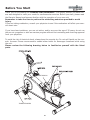
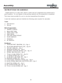
430r
Owner’s Manual
IRONMAN 430r RECUMBENT
Customer Service
1.800.750.IRON
1.800.750.4766
Ironman Fitness
4009 Distribution Drive
Suite 250
Garland, TX 75041
www.ironmanfitness.com
Model Name : 430r
Serial Number :
Write down for future reference
315-00082
Rev C 02/13
Serial Number Decal Location
Table of Contents
Important Safety Information
3
Before You Start
4
Assembly
5-9
Console Overview
10-15
Monitoring Your Heart Rate
16-17
Moving Instructions
18
Warm Up Exercises
19
Exploded View
20
Parts List
21
Warranty 22
2
Important Safety Information
WARNING! Before using this unit or starting any exercise program, consult your physician.
This is especially important for persons over the age of 35 and/or persons with pre-existing
health problems. The manufacturer or distributor assumes no responsibility for personal injury
or property damage sustained by or through the use of this product.
SAFETY PRECAUTIONS AND TIPS
1. It is the owner's responsibility to ensure that all users of this unit have read the Owner's
Manual and are familiar with warnings and safety precautions.
2. This unit has a user maximum capacity of 300 pounds.
3. The unit should only be used on a level surface and is intended for indoor use only. The unit
should not be placed in a garage, patio, or near water and should never be used while you are
wet. Ironman Fitness recommends a mat be placed under the unit to protect floor or carpet
and for easier cleaning.
4. Wear comfortable, good-quality walking or running shoes and appropriate clothing. Do not
use the unit with bare feet, sandals, socks or stockings.
5. Always examine your unit before using to ensure all parts are in working order.
6. Allow the unit to fully stop before dismounting.
7. Pets should never be allowed near the unit.
8. Do not leave children unsupervised near or on the unit.
9. Never operate the unit where oxygen is being administered, or where aerosol products are
being used.
10. Never insert any object or body parts into any opening.
11. For safety and to prevent damage to your unit, no more than one person should use the
unit at a time.
12. Service to your unit should only be performed by an authorized service representative,
unless authorized and/or instructed by the manufacturer.
13. Failure to follow these instructions will void the unit warranty.
3
Before You Start
Thank you for purchasing the Ironman 430r Recumbent! This quality product you have chosen was designed to meet your needs for cardiovascular exercise. Before you start, please read
the Owner's Manual and become familiar with the operation of your new unit.
Remember to take the time to perform the stretching exercises provided to avoid
injury.
If you are taking medication, consult your physician to see if the medication will affect your exercise heart rate.
If you have heart problems, you are not active, and/or are over the age of 35 years, do not use
the pre-set programs or start an exercise program without first contacting and receiving approval
from your physician.
To avoid the risk of electrical shock, always keep the console dry. Do not spill liquids on the console. Ironman Fitness recommends a sealed water bottle for beverages consumed while using
the unit.
Please review the following drawing below to familiarize yourself with the listed
parts.
SEAT CUSHION
TRANSPORT WHEELS
4
Assembly
INSTRUCTIONS FOR ASSEMBLY:
Unpack the box in a clear area. Check to make sure all components are present and in
good condition. Do not dispose of the packing material until the assembly is completed.
Tools have been provided for you to use when assembling this product.
Locate the hardware pack and identify the following parts required for assembly.
Tools:
1. Allen Wrench
2. Wrench
Main Components:
1. Owner’s Manual
2. REAR FOOT TUBE
3. FRONT FOOT TUBE
4. MAIN FRAME
5. LEFT AND RIGHT PEDALS
6. PULSE HANDLES
7. CONSOLE
8. AC ADAPTER
Hardware:
1. CARRIAGE BOLT M8X85MM (19) - Qty 4
2. M8 X19MM WASHER BLACK (49) - Qty 34
3. CAP NUT, 8MM (61) - Qty 4
4. M6X60MM SCREW (93) - Qty 8
5. WASHER, M6X16MM (BLACK) (63) - Qty 10
6. SCREW, M8X15MM (89) - Qty 8
7. TP M4 X 12MM SCREW (70) - Qty 30
8. 11*58MM SCREW (84) - Qty 2
9. ALLEN BOLT, M6X15MM (62) - Qty 4
10. M8X60MM SCREW (55) - Qty 3
11. 8 MM BLACK LOCKNUTS (THICK) (50) - Qty 8
12. BLACK SCREW, M8X15MM (LOCKTITED) (90) - Qty 2
13. M8X57MM SCREW (67) - Qty 3
14. M5 X10MM SCREW (39) - Qty 4
15. TP M4 X 16 MM SCREW (81) - Qty 2
5
Assembly
FIGURE 1
Figure 1
Step 1:
Attach Rear Foot Tube (4) to
Main Frame (1) with two Bolts
(19), two Washers (49) and
two Cap Nuts (61).
Step 2:
Attach Front Foot Tube (4)
with two Bolts (19), two
Washers (49) and two Cap
Nuts (61).
Figure 2
FIGURE 2
Step 1:
Attach Back Cushion (14) to
Seat Support Bracket (3) using
four Screws (93) and Washers
(63). Snap Seat Cover (57)
into place.
Step 2:
Attach Pulse Handlebars
(13A).to Seat Support Bracket
(3) using four Bolts (89) and
four Washers (49).
Step 3:
Install Seat Cushion (9) to
Seat Support Bracket (3) using
four Screws (93) and Washers
(63).
6
Assembly
Figure 3
FIGURE 3
Step 1:
Connect Cables (34a) to
(66a) and slide Endcap (80)
into place. Attach Endcap with
two Screws (70).
Note: Be careful not to pinch
the cables.
Step 2:
Slide Assembled Seat
Carriage (30) onto Seat
Bracket (21). Attach to brackets using one Screw (84),
Spacers (83), Washer (63), and
Nut (62).
FIGURE 4
Figure 4
Step 1:
Thread the Right Pedal (31)
into the right crank area of Main
Frame (1). Secure in place by
turning it clockwise to tighten.
Note: Right Pedal (31) is
marked with an “R”.
Step 2:
Thread the Left Pedal (30)
into the left crank area of Main
Frame (1). Secure in place by
turning it counter-clockwise
to tighten.
Note: Left Pedal (30) is marked
with an “L”
Step 3:
Place Clamp (99) over cables,
and secure using Screw (70).
7
Assembly
FIGURE 5
Step 1:
Connect Cables 8, 38, 37
and 66 as shown.
Step 2:
Attach Console Tube (2) to
Main Frame (1) using three
Screws (55), three Washers
(49), three Nuts (50), two
Screws (90) and two Washers
(49).
Step 3:
Attach Connecting Covers
(16) to Main Frame (1) by
sliding covers down console
tube until they meet main
frame. Use six Screws (70)
to attach Connecting Covers
to Main Frame.
Figure 5
Figure 6
FIGURE 6
Step 1:
Attach Front Handlebars (10)
to Console Tube (2) using two
Bolts (67) two Washers (49),
two Nuts (50), one Screw (89)
and one Washer (49).
8
Assembly
FIGURE 7
Figure 7
Step 1:
Connect the Pulse Wires
(66) and Extension Wires
(58) to Console (15). Secure
Console (15) to Console Tube
(2) using four Screws (39).
Note: The four Screws (39)
will already be installed into
the back of Console (15)
when you remove it from the
box.
Step 2:
Attach Water Bottle Holder
(2A) using two Screws (81).
Congratulations!
You have completed assembly of your new Ironman 430r
Recumbent!
9
Console Overview
CONSOLE BUTTONS:
MODE:
To set function value for TIME, DIST, CAL, PULSE.
RESET:
Return to main function mode in STOP mode and clean all preset function values at zero.
START/STOP:
To start or stop training
RECOVERY:
To test heart rate recovery status.
UP:
To select training mode and adjust function value up.
DOWN:
To select training mode and adjust function value down.
10
Console Overview
FAN:
Console is equipped with a fan that has four settings, AUTO/LOW/MED/HIGH/OFF. Press the
button to turn the fan to the preferred setting. The AUTO setting will adjust the fan speed
based on the RPMs produced, the more RPMs produced the faster the fan speed will be.
BODY FAT:
Press the button to start body fat measurement.
CONSOLE FUNCTIONS
TIME:
Count up - No preset target, Time will count up from 00:00 to maximum 99:59 with each
increment is 1 second. Count down - If training with preset Time, Time will count down from
preset to 00:00. Each preset increment or decrement is 1 minute between 1:00 to 99:00.
SPEED:
Display current training speed from 0.0 to maximum 99.9 KM or MPH.
RPM:
Display current training revolutions per minute.
DISTANCE:
Count up - No preset target, Distance will count up from 0.00 to maximum 99.90 with each
Increment 0.1 MPH/KM. Count down - If training with preset target, Distance will count down
from preset to 0.00. Each preset increment or decrement is 0.1 KM (or MPH) between 0.00 to
99.90.
CALORIES:
Count up - No preset target, Calories will count up from 0 to maximum 990 with each 1 cal
increment. Count down - If training with preset target, Calories will count down from preset
calorie to 0. Each preset increment or decrement is 10 cal from 0 to 990 cal.
PULSE:
Displays your current heart beat figures as soon as both hands are holding the pulse sensor.
The monitor will detect your heart rate through hand grip sensors.
WATT:
Display current training watt figures.
RECOVERY:
After exercising for a period of time, keep holding on handgrips and press “RECOVERY” button. All function display will stop except “TIME” starts counting down from 00:60 to 00:00.
Screen will display your heart rate recovery status with the F1, F2 to F6. F1 is the best, F6
is the worst. User may keep exercising to improve the heart rate recovery status. (Press the
RECOVERY button again to return the main display.)
11
Console Overview
CALENDAR:
Screen will display year/month/day in sleep mode. When the unit is plugged in the console will
prompt user to input correct information. Use the UP and DOWN button until correct year is
found. Press MODE to select and move on to the Month. Repeat to input correct month and day.
Note: All information will be saved until unit is unplugged.
CLOCK:
Screen will display time in sleep mode. Once the calendar is set, you will be able to input the
correct time. Use the UP and DOWN buttons until the correct hour found. Press MODE to select
and move on to the minutes. Repeat for to input correct minutes. Note: All information will be
saved until unit is unplugged.
TEMPERATURE:
Screen will display room temperature in sleep mode.
GENERAL INFORMATION:
1. Start Pedaling or press any button to start Console.
2. The Console will shut down after 4 minutes of no activity, and will display room temperature.
3. To Reset Console press and hold the START/STOP button for 2 seconds.
Note: The values calculated or measured by the console are for exercise purposes only, not for
medical purposes.
BMR:
Basal Metabolic Rate (metabolism) is the energy (measured in calories) expended by the body
at rest to maintain normal body functions.
BMI:
Stands for Body Mass Index. BMI is a measure which takes into account a person’s weight and
height to gauge total body fat in adults.
GETTING STARTED:
Press the MODE button. Press MODE to enter USER SELECT. Use the UP/DOWN to select a
User. Press MODE to select a User. Press the UP/DOWN key to select HEIGHT. Press MODE
to confirm the value. Use the UP/DOWN key to select WEIGHT. Press MODE to confirm value.
Use the UP/DOWN key to select AGE. Press MODE to confirm value. Use the UP/DOWN key to
select GENDER. Press MODE to confirm value. Press START/STOP to enter program mode.
PROGRAM INSTRUCTIONS:
MANUAL PROGRAM:
Allows the User to manually adjust tension settings throughout their workout. The default
tension level is 6. You may set Time or Distance for your workout.
12
Console Overview
Use the UP/DOWN buttons to scroll to this program. Press MODE to select this program. TIME
will flash in the display. Use the UP/DOWN keys to set desired TIME. Press MODE to confirm
value. Repeat steps for DISTANCE and KCAL. Press START/STOP to begin exercising. Grasp
Pulse Grips loosely with both hands to activate PULSE function. You can change the tension
level at any time during your workout session by pressing the UP/DOWN buttons.
PRESET PROGRAMS:
Each Program is divided into ten intervals.
Use the UP/DOWN buttons to scroll to this program. Press MODE to select this program. TIME
will flash in the display. Use the UP/DOWN keys to set desired TIME. Press MODE to confirm
value. Repeat steps for DISTANCE and KCAL. Press START/STOP to begin exercising. Grasp
Pulse Grips loosely with both hands to activate PULSE function.
USER PROGRAM:
It allows you to customize a workout session. This program is divided into 10 intervals. TIME,
DISTANCE, KCAL and Tension can be set for each interval. The program will be stored in the
Console’s memory after set-up.
Use the UP/DOWN buttons to scroll to this program. Press MODE to select this program. TIME
will flash in the display. Use the UP/DOWN keys to set desired TIME. Press MODE to confirm
value. Repeat steps for DISTANCE and KCAL. Column 1 will flash on display. Use the UP/
DOWN keys to set Tension for this interval. Press MODE to confirm value. Repeat for Interval
2-10. Press START/STOP to begin exercising. Grasp Pulse Grips loosely with both hands to
activate PULSE function. You can change the tension level at any time during your workout
session by pressing the UP/DOWN buttons. If the tension level is changed during your exercise
session, this new value will not be saved into the console.
To make a permanent change, you must call up program again and repeat steps for each interval with new tension settings.
WATT PROGRAM:
In the program, the WATT function will keep a constant value. This means that if you pedal
quickly, the tension will decrease, if you pedal slowly the tension will increase to maintain the
Watt value entered.
WATT = TORQUE (KGM) * RPM *1.03. For this program you must choose to set a TIME or a
DISTANCE. Use the UP/DOWN buttons to scroll to this program. Press MODE to select this
program. TIME will flash in the display. Use the UP/DOWN keys to set desired TIME. Press
MODE to confirm value. Repeat steps for DISTANCE, KCAL and WATT. Press START/STOP to
begin exercising. Grasp Pulse Grips loosely with both hands to activate PULSE function.
HEART RATE PROGRAMS:
Heart rate control programs are designed to automatically adjust the elliptical's resistance to
keep your heart rate at a predetermined level based on the selected Heart Rate program. Each
Heart Rate program is designed with a specific goal.
13
Console Overview
There are three Heart Rate Programs. 60% HRC (Heart Rate Control), 75% HRC and 85%
HRC. The Console will adjust the Tension to keep you within your Target Heart Rate ± 5.
Example: The tension will increase if your Heart Rate is below the Target Heart Rate. The
tension will decrease if your Heart Rate is higher that your Target Heart Rate.
Press MODE until Program number shows on display. Use the UP/DOWN buttons to scroll to
this program. Press MODE and set values for TIME, DISTANCE, KCAL, AGE and TARGET HEART
RATE. Use the UP/DOWN keys to adjust the values. Press MODE after correct value shows on
display. Press START/STOP to begin exercising. Grasp Pulse Grips loosely with both hands to
activate PULSE function. You may also choose the TARGET HEART RATE WORKING PROGRAM
under the 3 main HEART RATE PROGRAMS. This allows the user to set a TARGET HEART RATE
to exercise at for a period of TIME or a set DISTANCE.
BODY FAT PROGRAM:
This program is designed to calculate body fat ratio and to design a specific tension profile. In
order to use this program correctly, make sure the personal data has been input and correct.
Press the BODY FAT button, and hold on to the hand grips to start body fat testing. The console
will display "- - - - - - - - " while testing is in progress. After 8 seconds, you will see the BODY
FAT in percentage and BMI. If the console has experienced an error, it will display on of the following error codes:
"E-1" - When the console displays this error, it means you did not put your hands
properly on the sensor. Please try again.
"E-4" - When the console displays this error, it means that the BODY FAT is out of range.
After BODY FAT testing is completed, press the BODYFAT button to continue workout.
Note: For a more accurate reading, hold the handgrip with both hands. This is
especially important in Heart Rate Mode or when performing Body Fat or Fitness Test.
14
Console Overview
FITNESS TEST: (Pulse Recovery Feature)
The fitness test compares your pulse rate before and after training. You will notice that your
fitness will improve with regular exercise.
Press the PULSE RECOVERY button immediately after your workout. Grasp the Pulse Grips.
Timer will count down from 60 seconds. Your personal fitness will display on the screen. (F1F6)
F1
F2
F3
F4
F5
F6
=
=
=
=
=
=
Excellent
Good
Fair
Below Average
Poor
Very Poor
15
Monitoring Your Heart Rate
Monitoring Your Heart Rate
To obtain the greatest cardiovascular benefits from your exercise workout, it is important to
work within your target heart rate zone. The American Heart Association (AHA) defines this target as 60%-75% percent of your maximum heart rate.
Your maximum heart rate may be roughly calculated by subtracting your age from 220. Your
maximum heart rate and aerobic capacity naturally decreases as you age. This may vary from
one person to another, but use this number to find your approximate effective target zone. For
example, the maximum heart rate for an average 40 year-old is 180 bpm. The target heart
rate zone is 60%-75% of 180 or 108-135 bpm. See Fitness Safety below.
Before beginning your workout, check your normal resting heart rate. Place your fingers lightly
against your neck, or against your wrist over the main artery. After finding your pulse, count
the number of beats in 10 seconds. Multiply the number of beats by six to determine your
pulse rate per minute. We recommend taking your heart rate at these times; at rest, after
warming up, during your workout and two minutes into your cool down, to accurately track
your progress as it relates to better fitness.
During your first several months of exercising, the AHA recommends aiming for the lower part
of the target heart rate zone-60%, then gradually progressing up to 75%.
According to the AHA, exercising above 75% of your maximum heart rate may be too strenuous unless you are in top physical condition. Exercising below 60% of your maximum will result
in minimal cardiovascular conditioning.
Check your pulse recovery rate – If your pulse is over 100 bpm five minutes after you stop
exercising, or if it’s higher than normal the morning after exercising, your exertion may have
been too strenuous for your current fitness level. Rest and reduce the intensity next time.
Fitness Safety The target heart rate chart indicates average rate zones for different ages. A
variety of different factors (including medication, emotional state, temperature and other conditions) can affect the target heart rate zone that is best for you. Your physician or health care
professional can help you determine the exercise intensity that is appropriate for your age and
condition.
(MHR) = Maximum Heart Rate
(THR) = Target Heart Rate
220 - age = maximum heart rate (MHZ)
MHZ x .60 = 60% of your maximum heart rate.
MHZ x .75 = 75% of your maximum heart rate.
For example, if you are 30 years old, your calculations will be as
follows:
220 - 30 = 190
190 x .60 = 114 (low end or 60% of MHZ)
190 x .75 = 142 (high end or 75% of MHZ)
30 year-old (THR) Target Heart Rate would be 114-142
See Heart Rate Table (on next page) for additional calculations.
16
Monitoring Your Heart Rate
TARGET HEART RATE ZONE
100%
200
195
190
185
180
Serious
athletic
training range
85%
170
166
162
Cardiovascular
conditioning
range
75%
150
146
143
157
139
153
135
Fat burning
range
60%
120
20
117
25
114
30
111
35
108
40
175
149
131
105
45
AGE
17
170
145
128
165
140
124
160
136
120
102
99
96
50
55
60
155
132
116
93
65
Moving Instructions
CAUTION! TO REDUCE THE POSSIBILITY OF INJURY WHILE LIFTING, BEND YOUR LEGS AND
KEEP YOUR BACK STRAIGHT. AS YOU LEAN THE UNIT, LIFT USING YOUR LEGS, NOT YOUR
BACK.
First, kneel down and grasp the rear support tube with both hands as shown in Figure 1.
Next, with a firm grasp on rear support tube stand up bringing the rear of the bike up in the
air and tilt the unit until it rolls freely on the transport wheels. Using extreme caution, move
the unit to the desired location as shown in Figure 2. Do not attempt to move the unit over an
uneven or rough surface.
Note: The unit you purchased may not be identical to the one pictured.
Figure 2
Figure 1
Note: This unit may not be identical to your unit.
18
Warm Up Exercises
EXERCISE GUIDELINES
WARNING! Before beginning this or any exercise program, you should consult your physician. This is especially important for individuals over the age of 35 or individuals with pre-existing health problems.
Warming up prepares the body for the exercise by increasing circulation, supplying more oxygen to the muscles and raising body temperature. Begin each workout with 5 to 10 minutes of
stretching and light exercise to warm up. The photos on this page show several forms of basic
stretching you may perform before your workouts. In order to achieve an adequate warm-up,
perform each stretch three times.
TOE TOUCH STRETCH
Stand bending your knees slightly and slowly bend forward from
your hips. Allow your back and shoulders to relax as you reach
down toward your toes as far as possible. Hold for 15 counts,
then relax. This will stretch your hamstrings, back of knees, and
back.
HAMSTRING STRETCH
Sit with one leg extended. Bring the sole of the opposite foot
toward you and rest it against the inner thigh of your extended
leg. Reach toward your toes as far as possible. Hold for 15
counts, then relax. This will stretch your hamstrings, lower back,
and groin.
CALF/ACHILLES STRETCH
With one leg in front of the other, reach forward and place your
hands against a wall. Keep your back leg straight and your back
foot flat on the floor. Bend your front leg, lean forward and move
your hips toward the wall. Hold for 15 counts, then relax. To
cause further stretching of the Achilles tendon, bend your back
leg as well. This will stretch your calves, Achilles tendons, and
ankles.
QUADRICEPS STRETCH
With one hand against a wall for balance, reach back and grasp
one foot with your other hand. Bring your heel as close to your
buttocks as possible. Hold for 15 counts, then relax. This will
stretch your quadriceps and hip muscles.
INNER THIGH STRETCH (Image not Shown)
Sit with the soles of your feet together and your knees outward.
Pull your feet toward your groin area as far as possible. Hold for
15 counts, then relax. This will stretch your quadriceps and hip
muscles.
19
Exploded View
20
Parts List
430r Recumbent Bike Parts List Rev A
Ref #
Part #
Description
Qty
Ref #
1
323-00369
FRAME, 420R
1
48
302-00375
Part #
M8X38MM SCREW
Description
2
323-00370
CONSOLE TUBE, 420R
1
49
302-00449
M8X19MM WASHER BLACK U/R/E 220/240/250
Qty
1
34
2A
310-00012
BOTTLE RACK CM835/850 HT840 ALL900/920/5
1
50
302-01231
8MM BLACK LOCKNUT (THICK)
8
3
323-00371
SEAT CARRIAGE, 420R
1
51
302-00765
SPRING, HT840R/HT840U.1/420R
1
4
323-00014
FOOT TUBE, 420R/HT840R.1/400R
2
52
302-00467
TP M3 X8MM SCREW 220R/240R/640R/520e/250
2
5
306-00652
TOP COVER, 420R/HT840R.1
1
53
302-01232
PHILLIP SCREW, M5X15MM
4
6
311-00059
PULLEY HT840U/R/EL/420R/520E
1
54
302-01198
HEX HEAD SCREW, M8 X 20MM
1
7
311-00001
MAG BRAKE U/R HT840/ 420r
1
55
302-00377
M8X60MM SCREW
3
8
307-00128
GEAR BOX W/WIRE, 430R
1
56
302-00488
M8 X 45MM BUTTON HEAD SCREW
1
8A
310-00182
TENSION CABLE (DRIVE CABLE), 420R
1
57
328-00063
BACK CUSHION COVER, 420R/HT840R.1
1
9
328-00064
SEAT CUSHION, 420R
1
58
313-00356
DC POWER CORD, 430R
1
1
10
323-00368
FRONT HANDLEBAR, 420R
1
59
319-00219
CARRIAGE SUPPORT PLATE, 420R/HT840R.1
10A
302-00816
FRONT SLEEVE, HT840R/420R
2
60
319-00220
ADJUSTING PLATE, 420R/HT840R.1
1
11
305-00061
BOTTOM LEFT COVER, HT840R/420R
1
61
302-01233
CAP NUT, 8MM
4
11A
305-00062
BOTTOM RIGHT COVER, HT840R/420R
1
62
302-01234
ALLEN BOLT, M6X15MM
12
305-00132
LEFT REAR COVER, 420R/HT840R.1
1
63
302-00444
WASHER, M6X16MM (BLACK)
10
4
12A
305-00133
RIGHT REAR COVER, 420R/HT840R.1
1
64
313-00358
HAND PULSE SENSOR, 430R
2
13
323-00366
REAR HANDLEBAR, 420R/HT840R.1
1
64A
313-00359
WIRE, HAND PULSE 430R
2
13A
310-00179
REAR SLEEVE, 420R/HT840R.1
1
65
306-00372
1 1/4" BALL PLUG 220R/240R/240U/640R/520
2
14
328-00062
BACK CUSHION, 420R/HT840R.1
1
66
313-00360
WIRE, SHORT EXTENSION PULSE, 430R
1
15
307-00127
CONSOLE, 430R/530E
1
66A
313-00361
WIRE, LONG EXTENSION PULSE, 430R
1
16
306-00653
CONSOLE TUBE COLLAR, 420R/HT840R.1
1
67
302-00376
M8X57MM SCREW
3
17
306-00195
WHEEL U/R CM835/850 HT840 AB900/920/420
2
68
305-00134
ROUND COVER, 420R/HT840R.1
2
18
306-00051
FOOT CAP U/R CM835/850 HT840 AB900/920
2
69
306-00626
END CAP 20 X 40
19
302-00364
M8X85MM CARRDIAGE BOLT
4
70
302-00416
TP M4 X 12MM SCREW
35
7
2
20
319-00177
AXLE W/PLATE, HT840R/HT840U.1/420R/500e
1
71
302-00417
TP M5 X50MM SCREW
21
323-00003
CARRIAGE TUBE CM835/850 HT840 ALL900/920
1
72
302-01255
BLACK LOCKNUT, M8 THIN
9
22
330-00015
LEFT CRANK, HT840R/HT840U.1/420R
1
73
302-01235
SCREW, TPM5X10MM
2
22A
330-00016
RIGHT CRANK,HT840R/HT840U.1420R
1
74
302-01236
BIASED SCREW, M8X34MM
2
23
306-00654
END PLUG, 420R/HT840R.1
1
75
306-00655
SMALL ROLLER, 420R/HT840R.1
2
24
306-00562
CRANK CENTRAL CAP, HT840U/R/420R
2
76
306-00648
SPACER, 20X13.3X2t
2
25
302-00369
M10 CAP NUT
2
77
302-00349
M8 WAVED WASHER
2
26
302-01199
M8X12.5X10L SPACER
1
78
302-01237
WASHER, 8X16X1.0 (SILVER)
2
27
302-00774
CRANK NUT, HT840R/HT840U.1/420R
1
79
302-01238
WASHER, 8X16X2.0 (BLACK)
2
28
302-01226
WASHER M20X30X2, (SILVER)
1
80
306-00040
END CAP R CM835/850 HT840 ALL900/ 420R
1
29
331-00091
PRECISE BEARING, #6004
2
81
302-01192
TP M4 X 16 MM SCREW
2
1
30
306-00621
PEDAL, LEFT, 400R/420R/HT840R.1/HT840U.1
1
82
302-01239
WASHER, M20X30X1 (SILVER)
30A
306-00361
LEFT PEDAL STRAP 400R/420R/HT840R.1/HT84
1
83
306-00252
RUBBER STOPPER CM835/850 HT840 ALL900/92
4
31
306-00362
RIGHT PEDAL 400R, 420r/HT840R/HT840U.1
1
84
302-00355
11*58MM SCREW
2
31A
306-00363
RIGHT PEDAL STRAP 400R/420R/HT840R.1
1
85
306-00658
PLASTIC COIL, 420R
1
32
302-01227
HEX BOLT, M6X20 (SILVER)
4
86
306-00656
LARGE ROLLER, 420R/HT840R.1
4
33
302-01228
LOCKNUT, 6MM (SILVER)
4
87
306-00649
METAL BUSHING, L737
4
34
302-01266
MAGNET, 420R
1
88
302-01240
ROUND HEAD SCREW, M8X34MM
4
35
304-00018
BELT, POLY V BELT, 420R/HT840R.1
1
89
302-01241
SCREW, M8 x 15mm (BLACK)
8
36
323-00367
REAR SUPPORT TUBE, 420R/HT840R.1
1
90
302-01242
BLACK SCREW, M8X15MM (LOCKTITED)
2
37
313-00356
DC POWER CORD, 430R
1
91
302-00408
EYEBOLT 6 x 65MM
1
38
307-00129
SENSOR, 430R
1
92
302-00409
M6 HEX NUT (BLACK)
2
39
302-00380
M5 X10MM SCREW
4
93
302-00452
M6x60MM SCREW 220R/240R/420R/250R
8
40
302-01195
EYEBOLT 6 X 40MM
2
94
302-00460
M8 X75MM HEX HEAD SCREW
2
41
302-00399
ADJUSTMENT CHANNEL ALL MACRO BIKES
2
95
310-00180
CAM LOCK, 420R/HT840R.1
1
42
302-00369
M10 CAP NUT
2
96
310-00181
CAM LOCK HANDLE, 420R/HT840R.1
1
43
302-01229
HEX NUT, 6MM (SILVER)
2
96A
306-00657
CAM LOCK CAP, 420R/HT840R.1
1
44
302-01230
WASHER, M10X19MM (BLACK)
2
97
302-01264
CAM LOCK SPRING, 420R/HT840R.1
1
45
319-00175
BELT TENSION BRACKET,HT840R/HT840U.1,420
1
98
302-01265
CAM LOCK PIN, 420R/HT840R.1
1
46
311-00032
IDLER PULLEY U/R/ET CM835/850 HT840 AB90
1
99
306-00690
CABLE CLAMP, 430R
1
47
331-00002
608 PRECISE BEARING
6
#
315-00082
OWNERS MANUAL 430R
1
21
Warranty Information
Residential Warranty
Frame: Lifetime
Parts: 1 Year
This Limited Warranty applies in the United States and Canada to products manufactured or
distributed by Ironman Fitness (“Ironman”) under the Ironman brand name. The warranty period to the original purchaser is listed above in the table.
Ironman warrants that the Product you have purchased for use from Ironman or from an
authorized Ironman reseller is free from defects in materials or workmanship under normal use
during the warranty period. Your sales receipt, showing the date of purchase of the Product,
is your proof of purchase. This warranty only extends to you, the original purchaser. It is not
transferable to anyone who subsequently purchases the Product from you. It excludes expendable parts (wear items). Wear items pertain to components that might need to be replaced
due to normal wear and tear. These items vary per product but will include pedal straps, seats,
grips, chains, bottom bracket assemblies, pads, etc. Please contact an Ironman customer service representative for specifics on wear items. This Limited Warranty becomes VALID ONLY if
the product is purchased through an Ironman Fitness authorized dealer unless otherwise authorized by Ironman Fitness in writing.
During the warranty period Ironman will repair or replace (at Ironman’s option) the product
if it becomes defective, malfunctions, or otherwise fails to conform with this Limited Warranty
under normal use. In repairing the Product, Ironman may replace defective parts, or at the
option of Ironman, serviceable used parts that are equivalent to new parts in performance.
All exchanged parts and Products replaced under this warranty will become the property of
Ironman. Ironman reserves the right to change manufacturers of any part to cover any existing
warranty.
This warranty DOES NOT COVER shipping charges, export taxes, custom duties and taxes, or
any other charges associated with transportation of the parts or Product.
To obtain warranty service, you must contact an Ironman authorized retailer, service technician or Ironman Fitness at our phone number located in this manual. Any parts determined to
be defective must be returned to Ironman to obtain warranty service. You must prepay any
shipping charges, export taxes, custom duties and taxes, or any other charges associated with
transportation of the parts or Product. In addition, you are responsible for insuring any parts
or Product shipped or returned. You assume the risk of loss during shipment. You must present
Ironman with proof-of-purchase documents (including the date of purchase). Any evidence of
alteration, erasing or forgery of proof-of-purchase documents will be cause to void this Limited
Warranty.
This warranty does not extend to any product not purchased from Ironman or from an authorized Ironman reseller. This Limited Warranty does not extend to any Product that has been
damaged or rendered defective; (a) as a result of accident, misuse, or abuse; (b) by the use
of parts not manufactured or sold by Ironman; (c) by modification of the Product or normal
wear and tear; (d) operation on incorrect power supplies; or (e) as a result of service by anyone other than Ironman, or an authorized Ironman warranty service provider. Product on which
the serial number has been defaced or removed is not eligible for warranty service. Should any
Product submitted for warranty service be found ineligible, an estimate of repair cost will be
furnished and the repair will be made if requested by you upon Ironman’s receipt of payment
or acceptable arrangements for payment.
EXCEPT AS EXPRESSLY SET FORTH IN THIS WARRANTY, IRONMAN MAKES NO OTHER
WARRANTIES, EXPRESSED OR IMPLIED, INCLUDING ANY IMPLIED WARRANTIES OF
MERCHANTABILITY AND FITNESS FOR A PARTICULAR PURPOSE. IRONMAN EXPRESSLY
DISCLAIMS ALL WARRANTIES NOT STATED IN THIS LIMITED WARRANTY. ANY IMPLIED
WARRANTIES THAT MAY BE IMPOSED BY LAW ARE LIMITED TO THE TERMS OF THIS LIMITED
WARRANTY. NEITHER IRONMAN NOR ANY OF ITS AFFILIATES SHALL BE RESPONSIBLE FOR
INCIDENTAL OR CONSEQUENTIAL DAMAGES. SOME STATES DO NOT ALLOW LIMITATIONS
ON HOW LONG AN IMPLIED WARRANTY LASTS OR THE EXCLUSION OR LIMITATION OF
INCIDENTAL OR CONSEQUENTIAL DAMAGES, SO THE ABOVE LIMITATIONS OR EXCLUSION
MAY NOT APPLY TO YOU. This Limited Warranty gives you specific legal rights and you may
also have other rights that may vary from state to state. This is the only expressed warranty
applicable to Ironman-branded products. Ironman neither assumes nor authorizes anyone to
assume for it any other express warranty.
PLEASE SEND IN THE ATTACHED WARRANTY CARD WITHIN TEN (10) DAYS OF PURCHASE TO
REGISTER YOUR UNIT WITH IRONMAN FITNESS, OR ONLINE AT WWWW.IRONMANFITNESS.
COM.
22
Customer Service
1.888.340.0482
Keys Fitness
4009 Distribution Drive
Suite 250
Garland, TX 75041
www.keysfitness.com
Ironman and M-dot are registered trademarks of the World Triathlon Corp., used here by permission.