1
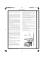
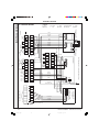
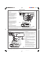
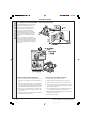
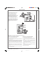
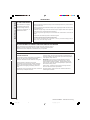
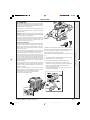
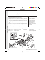
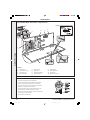
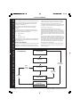
INSTALLATION
& SERVICING
Concord
CXSi 110/H-180/H
BOILERS
157294-3.pmd
1
11/8/2005, 9:58 AM
Installers guide to commercial central heating boilers
MANUAL
GENERAL
Concord CXSi/H - Installation & Servicing
2
157294-3.pmd
2
11/8/2005, 9:58 AM
GENERAL
Table 1 - Performance Data
Boiler
CXSi 110/H
Boiler Input
Gross
kW
Low Rate
Btu/h x 1000
Nett
Boiler Input
kW
CXSi 140/H
CXSi 160/H
119.5
136.6
CXSi 180/H
93.9
102.5
153.7
320.5
349.6
407.9
466.1
524.4
84.6
92.3
107.7
123.1
138.5
Btu/h x 1000
288.7
315.0
367.4
419.9
472.4
kW
134.2
146.4
170.8
195.2
219.6
Btu/h x 1000
457.8
499.4
582.7
665.9
749.1
kW
120.9
131.9
153.8
175.8
197.8
Btu/h x 1000
412.4
449.9
524.9
599.9
674.9
Gross
High Rate
CXSi 120/H
Nett
Boiler Output
110
120
140
160
180
Btu/h x 1000
kW
375.3
409.4
477.7
545.9
614.2
m3/h
12.78
13.95
16.27
18.59
20.92
ft3/h
451.5
492.5
574.6
656.7
738.8
Approx. flue At 4.5% CO2 & 100°C
m3/h
0.112
0.122
0.142
0.163
0.183
gas volume
High Rate
Gas rate
High
At 4.5% CO2 & 212°F
Burner
High
setting
pressure
Low
Part load efficiency
3
ft /h
237
259
301
345
388
mbar
10.4
10.1
9.7
9.6
9.7
in.w.g.
4.2
4.0
3.9
3.8
3.9
mbar
5.1
4.9
4.8
4.7
4.8
in.w.g.
2.0
2.0
1.9
1.9
1.9
83.0
81.6
82.5
82.9
82.8
%
Note. To obtain gas consumption in l/s divide gross heat input (kW) by a calorific value of 37.8(MJ/m2)
Table 2 - General Data
Boiler
CXSi 110/H
CXSi 120/H
CXSi 140/H
CXSi 160/H
CXSi 180/H
7
7
8
9
10
Number of sections
Flow connections
Rc
Return tappings
65 mm (2 1/2") nominal bore. Flange to BS.4504 (PN6)
Rc
Maximum static head
2x2
m. (ft)
Maximum pressure
61.0 (200)
bar (psi)
Gas inlet connection
6.0 (87)
Rc
Minimum dynamic
gas pressure
mbar
in.
1 1/2
17.5
7
Electricity supply
17.5
7
17.5
7
17.5
7
230 Volts - single phase, 50 Hz, fuse 5 A
Nominal flue size (to BS. 835)
Diverter outlet socket
internal diameter
Length of burner bars (overall)
Approximate dry weight
Water content
mm
250
250
250
250
in.
10
10
10
10
12
mm
288
288
288
288
344
3
300
in.
11.3
11.3
11.3
11.3
13.5
mm
in
535
21.1
535
21.1
535
21.1
535
21.1
535
21.1
kg
538
538
608
678
748
lb.
1186
1186
1340
1494
1648
litre
53
53
60
68
76
gal.
11.7
11.7
13
15
17
Concord CXSi/H - Installation & Servicing
157294-3.pmd
17.5
7
3
11/8/2005, 9:58 AM
GENERAL
Concord CXSi 110/H-180/H (Natural gas)
B.G. Certified - P.I. No. 87/AQ/341
CONTENTS
Air Supply. ........................................................................ 9
Boiler Assembly - exploded view. ............................... 10
Boiler Clearances. ........................................................... 6
Burner Assemblies - exploded views. ............................
CXSi 110/H-160/H. ................................................. 25
CXSi 180/H. ............................................................ 26
Destination Countries: GB and IE
INTRODUCTION
CONSTRUCTION
BOILER BODY
The sectional boiler body is of cast iron and is supplied with a sheet
steel combustion chamber and integral draught diverter. The boiler
is supplied in sectioned form for site assembly.
CASING
The casing is manufactured in stove enamelled sheet steel and is
easily assembled on site.
BURNERS
The burners are of stainless steel construction.
Casing Assembly. ......................................................... 14
Chimney System. ............................................................ 9
Commissioning. ............................................................ 20
Electrical Connections. ................................................ 17
Electrical Supply. ............................................................ 9
Fault Finding. ................................................................ 29
Gas Safety Regulations .................................................. 4
Gas Supply. ...................................................................... 9
Hydraulic Resistance. ..................................................... 6
Initial Lighting. .............................................................. 21
Installation. .................................................................... 10
Mandatory Requirements. .............................................. 8
CURRENT GAS SAFETY (INSTALLATION AND USE)
REGULATIONS OR RULES IN FORCE.
It is the law that all gas appliances are installed and serviced by a
CORGI registered installer in accordance with the above regulations.
Failure to install appliances correctly could lead to prosecution. It
is in your own interest, and that of safety, to ensure that the law is
complied with.
The Concord CXSi 110/H-180/H range of boilers has been tested
and certified by British Gas to prEN656 for use with natural gas
only.
Note. Concord CXSi 110/H - 180/H boilers are intended for use
as COMMERCIAL BOILERS and are NOT certified for use in
domestic applications. A domestic installation is defined as an
installation where the boiler takes its combustion air from a living
space or from a room directly or indirectly connected with the
living space. It is important, therefore, that no external control
devices - e.g. flue dampers, economisers etc., are directly
connected to this appliance unless covered by these Installation
and Servicing Instructions or otherwise recommended by
Caradon Ideal Limited in writing. If in doubt please enquire.
Pump. ............................................................................... 7
Any direct connection of a control device not approved by Caradon
Ideal Limited could invalidate the British Gas Certification, the
normal appliance warranty and could also infringe the Gas Safety
Regulations. Table 1, Table 2 and the descriptive notes which follow
contain all the essential data likely to be required by the installer.
Servicing. ....................................................................... 24
GAS CONTROLS
Option Kits. ...................................................................... 5
System Connections. .................................................... 13
The boiler lights at Low rate (approximately 70% of Full rate) by
direct burner ignition. After about 1 minute the boiler goes to High
rate and will continue at High rate until the thermostat sensor set
point is reached. The boiler will then drop to the Low rate; if the
temperature continues to rise the boiler will go Off; if the
temperature falls the boiler will revert to High rate.
Ventilation. ....................................................................... 9
ELECTRICAL CONTROLS
Short List of Parts. ........................................................ 31
Static Head Requirements. ............................................ 7
Water Circulation. ........................................................... 5
Water Connections. ........................................................ 5
Water Treatment. ............................................................. 7
Wiring Diagrams. .......................................................... 19
The boiler is supplied with 2 printed circuit boards; Board
S4561B1047 is the ignition board containing the flame-proving logic;
Board W4115A1020 contains the electronic thermostat and pump
overrun timer. A preset overheat thermostat is also provided. The
mains voltage supply is via a terminal plug in connection at the
control box. The control box displays neons indicating boiler status
as follows:
- Boiler on
- Lockout
- Overheat
An anti-cycle delay is built in to the controls to prevent rapid cycling.
CAUTION. To avoid the possibility of injury during the installation, servicing or cleaning of
this appliance, care should be taken when handling edges of sheet steel components.
Concord CXSi/H - Installation & Servicing
4
157294-3.pmd
4
11/8/2005, 9:58 AM
GENERAL
FROST PROTECTION
WATER CIRCULATION SYSTEM
Frost protection is incorporated in the boiler as long as there is a
permanent Live supply wired to Terminal L1 on the terminal plug-in
connection at the control box and the boiler thermostat knob is not
switched to Off.
If the temperature sensed by the boiler thermostat falls to about
50C the boiler will fire until the temperature reaches 180C.
Note that this is designed to protect the boiler and may not
necessarily protect remote parts of the system.
The mains voltage supply is via a terminal plug-in connection at the
control box.
OPTION KITS
1. The minimum flow rate as given in Table 4 must be maintained
whenever the boiler is firing and during the pump overrun period.
2. During the period of pump overrun there must be an open circuit
of adequate water volume and/or load. The minimum size of
this circuit is given by the use of Graph 1.
Examples shown on Graph 1
Remote Indication Kit
This kit gives the facility of remote indication of boiler status.
Pressure Gauge Kit
A pressure gauge kit is available.
a. For the CXSi 110/H and CXSi 120/H the minimum circuit
during pump overrun could be a load of 7 kW with a volume
of 42 litres or any other combination given by the relevant
line.
b. For the CXSi 180/H the minimum circuit during pump overrun
could be a load of 9 kW with a volume of 70 litres or any
other combination given by the relevant line.
DUTY
The range of boilers is suitable for: Combined indirect pumped
domestic hot water and central heating systems; Independent
indirect pumped domestic hot water or central heating systems.
Fully pumped systems may be open vented or sealed.
The range of boilers is NOT suitable for:
The above circuit capacity during pump overrun may be achieved
either by provision of an adequate bypass circuit or by ensuring
that a zone of suitable size is open for circulation during this
period by relevant control of zone valves or pumps.
The wiring diagrams in Frames 16,17 &18 illustrate the control
methods for achieving the above.
1. Gravity DHW systems.
2. Gravity heating systems.
3. Direct domestic hot water supply.
1
Due to the compact nature of the boiler the heat stored within the
castings at the point of shutdown of the burner must be dissipated
into the water circuit in order to avoid the overheat thermostat
tripping. In order to allow pump operation after burner shutdown
the boiler control box incorporates a pump overrun facility which
operates for approximately 6 minutes after the burner shuts down
and, in order to make use of this, the pump must be wired to the
appropriate terminal L2 (pump) in the boiler control box.
3. Pump selection should take account of the hydraulic resistance
given in Graph 2.
WATER CONNECTIONS
Flow connection is 65mm (2 1/2") nominal bore flange to
BS.4504 (PN6)
Return tappings are 2" BSP.
Cold Feed/Open Vent
The independent cold feed and the open vent must comply
with BS. 6644 and be of the following minimum size.
The distributor tube must be fitted into the return connection.
The flow header must be fitted in the flow pipe.
The open vent must be brought to either the 1 1/2" BSP tapping
on the flow header or to the unused 2" BSP tapping at the top
rear of the boiler.
The cold feed may be brought to the LH front bottom tapping in
order to avoid excessive surging or pumping over. The unused
bottom rear tapping must not be used for the cold feed pipe as
it is practically blocked by the distributor tube.
Safety Valve
A safety valve must be sized and fitted in accordance with BS.
6644 for every type of system. The valve should be set at 0.7
bar (10 lb/in.2) above the operating pressure in the boiler. The
maximum safety valve setting is 0.7 bar (10 lb/in.2) above the
maximum design operating pressure of 6.0 bar (87 lb/in.2).
Boiler Size
Cold Feed
Open Vent
CXSi 110/H
1"
1 1/4"
CXSi 120/H
1"
1 1/4"
CXSi 140/H
1"
1 1/4"
CXSi 160/H
1 1/4"
1 1/2"
CXSi 180/H
1 1/4"
1 1/2"
Concord CXSi/H - Installation & Servicing
157294-3.pmd
5
5
11/8/2005, 9:58 AM
GENERAL
H
2
C
CXS XSi 14
i 12 0/H
0/H
CXSi 180/H
Con 1900
Si 1
10/
Con 1898
CX
CXSi 160/H
CXSi 110/H
CXSi 120/H
CX
CXS Si 180
i 16 /H
0/H
CXSi 140/H
Graph 2 - Hydraulic Resistance
Graph 1 - Heat Load / Water Volume
CLEARANCES & DIMENSIONS
Table 3
Boiler Size
CXSi 110/H
CXSi 120/H
CXSi 140/H
CXSi 160/H
CXSi 180/H
Front clearance
mm (in)
700 (27 1/2)
Rear clearance
mm (in)
200 (8)
Side clearance
mm (in)
100 (4) - not including clearance for side fitted flow header
Dimension A
mm (in) 1036 (40 3/4)
Dimension B
mm (in)
Dimension C
Dimension D
1036 (40 3/4)
1036 (40 3/4)
1086 (42 3/4)
1140 (45)
175 (7)
175 (7)
197 (7 3/4)
250 (10)
mm (in) 1107 (43 3/4)
1107 (43 3/4)
1230 (48 1/2)
1353 (53 1/4)
1476 (58 1/8)
mm (in)
816 (32 1/8)
816 (32 1/8)
939 (37)
1062 (42 3/4)
1185 (46 5/8)
Dimension E
mm (in)
553 (21 3/4)
553 (21 3/4)
615 (24 1/4)
676 (26 5/8)
738 (29)
Dimension F
mm (in)
220 (8 5/8)
220 (8 5/8)
220 (8 5/8)
220 (8 5/8)
320 (12 1/2)
175 (7)
1
POSITION OF BOILER
Minimum clearances required from walls or other fixed
objects to allow for the free access of combustion air are
shown in Table 3 above.
Any combustible material adjacent to the boiler and its flue
system must be so placed or shielded as to ensure that its
temperature does not exceed 65 0C (150 0F).
C O N C O R D +:5E
Con 1899
Return Rc
(2" BSP)
Concord CXSi/H - Installation & Servicing
6
157294-3.pmd
6
11/8/2005, 9:58 AM
GENERAL
PUMP POSITIONS
Whenever practically possible the circulating pump(s) should be
positioned so that it pressurises the system being served. The
vertical distance between the pump(s) and any cold feed and
expansion cistern MUST comply with the pump manufacturers
requirements, in order to avoid cavitation. These requirements
override the information given in Frame 3 if the static head required
for the pump(s) exceeds that required for the boiler.
MINIMUM FLOW OF WATER - Refer to Table 4
The system design must provide for an adequate flow rate through
the boiler at all times when the boiler is firing. The minimum flow
rate should correspond to a temperature difference across the boiler
flow and return of 35°C (63°F), assessed at catalogue rating.
Table 4 - Flow rates for fully pumped systems
Boiler
Minimum flow rates for a
temperature difference of 35°C (63°F)
l/s
g.p.m.
CXSi 110/H
0.75
9.9
CXSi 120/H
0.82
10.8
CXSi 140/H
0.96
12.7
CXSi 160/H
1.10
14.6
CXSi 180/H
1.24
16.4
WATER TREATMENT FOR HOT WATER AND
HEATING BOILERS
There is a basic need to treat the water contained in all heating and
indirect water systems, particularly open vented systems. It is
assumed, incorrectly, that because boilers are operating in
conjunction with what is apparently a closed circuit an open vented
system will not, under normal circumstances, allow damage or loss
of efficiency due to hardness salts and corrosion once the initial
charge of water has been heated up a few times.
1mm of lime reduces the heat transfer from metal to water by 10%.
In practice the deposition of these salts is liable to cause noises
from the boiler body or even premature boiler failure. Corrosion
and the formation of black iron oxide sludge will ultimately result in
premature radiator failure.
Open vented systems are not completely sealed from the
atmosphere if proper venting and expansion of system water is to
be achieved. The same tank is used to fill the system with water
and it is through the cold feed pipe that system water expands into
the tank when the boiler passes heat into the system. Conversely,
when the system cools, water previously expanded is drawn back
from the tank into the system, together with a quantity of dissolved
oxygen.
Even if leakage from the heating and hot water system is eliminated
there will be evaporation losses from the surface of the tank which,
depending upon ambient temperature, may be high enough to
3 OPEN VENTED SYSTEMS - minimum static head requirements
The information provided is based on the
following assumptions:
1. The open vent MUST be brought to either
the 1 1/2" BSP tapping on the flow header
provided or to the unused 2" BSP flow
tapping at the top rear of the boiler.
2. An independent cold feed/expansion pipe
connection is made to the LH lower front
connection. Cold feed/expansion pipe
connections made to the pumped system
return will result in an increase in the static
head requirement, caused by the
additional resistance of the distributor tube.
Surging may also increase.
3. The maximum flow rate through the boiler
is based on a temperature difference of
11°C at full boiler output and the circulating
pump is positioned in the flow to the
system.
Note. This diagram does not show safety valves, water flow
switches, etc., necessary for the safe operation of the system.
Particular reference should be made to BS. 6644: Section 2; Subsection
10 and Guidance note PM5 "Automatically controlled steam and hot
water boilers" published by the Health and Safety Executive.
The information and guidance given below is not intended to override any
requirements of either of the above publications or the requirements of
the local authority, gas or water undertakings.
Other British Standards applicable are BS.5422 and BS.6700.
4. The boiler is at the highest point of
circulation in the system. Systems
designed to rise above the boiler flow
tappings will automatically require a
minimum static head higher than that
shown.
5. The position of the open vent/safety pipe
above the expansion cistern water level is
given as a guide only. The final position will
depend upon the particular characteristics
of the system. Pumping over of water into
the expansion cistern must be avoided.
Concord CXSi/H - Installation & Servicing
157294-3.pmd
7
7
11/8/2005, 9:58 AM
GENERAL
evaporate a large portion of the system water capacity over a full
heating season.
There will always be corrosion within a heating or hot water system
to a greater or lesser degree, irrespective of water characteristics,
unless the initial fill water from the mains is treated. Even the water
in closed systems will promote corrosion unless treated.
For the reason stated Caradon Ideal Limited strongly recommend
that when necessary the system is thoroughly cleaned, prior to the
use of stable inhibitor, which does not require continual topping up
to combat the effects of hardness salts and corrosion on the heat
exchangers of the boiler and associated systems.
Limitations of Intended Operating Environment
These appliances are NOT suitable for installation where they will
be exposed to the elements.
A boiler room shall be constructed or adapted to meet the
requirements of BS 6644.
The maximum ambient temperature is 32 °C at 1.5 metres from the
floor with a maximum humidity of 90% RH.
FOR SMALL PIPE INSTALLATIONS;
BS. 6891:
Installation of low pressure pipework
Caradon Ideal Limited advise contact directly with specialists on
water treatment such as:
FOR LARGE PIPE INSTALLATIONS
Fernox Manufacturing Co. Ltd.,
Tandem House, Marlowe Way
Croydon.
Surrey CRO 4XS
Tel 0870 601 5000
IGE-UP-1:
Purging Procedures of Non-domestic Gas
Installations. Soundness Testing Procedures
for Industrial and Commercial.
IGE-UP-2:
Guidance notes on the Installation of Gas
Pipework, Boosters and Compressors in
Customer’s Premises Equal to or Greater than
25mm (Non-domestic).
IGE-UP-10:
Installation of Gas Appliances in Industrial and
Commercial Premises.
BS.6644:
Installation of Gas Fired Hot Water Boilers
70kW to 1.8MW (net).
or
Sentinel Division,
Betz Dearborn Ltd.,
Widnes,
Cheshire, WA8 8UD
Tel. 0151 424 5351.
SAFE HANDLING OF SUBSTANCES
Care should be taken when handling the boiler insulation panels,
which can cause irritation to the skin. No asbestos, mercury or
CFCs are included in any part of the boiler.
INSTALLATION REQUIREMENTS
The appliance must be installed by a CORGI registered installer,
The installation of the boiler must be in accordance with the relevant
requirements of the Gas Safety Regulations, current I.E.E.
(BS.7671) Regulations, Model Water Bye-laws, local water
authority bye-laws and it should also comply with any relevant
requirements of the local gas supplier, local authority and the
relevant British Standard Codes of practice and building
regulations.
4
SEALED (PRESSURISED) SYSTEMS
Working pressure 6.0 bar maximum.
Particular reference should be made to BS. 6644: Section 6
and Guidance note PM5 "Automatically controlled steam and
hot water boilers" published by the Health and Safety Executive.
The information and guidance given below is not intended to
override any requirements of either of the above publications or
the requirements of the local authority, gas or water undertakings.
In general commercial closed pressurised systems are provided
with either manual or automatic water make up.
On both instances it will be necessary to fit automatic controls
intended to protect the boiler, circulating system and ancillary
equipment by shutting down the boiler plant if a potentially
hazardous situation should arise.
Examples of such situations are low water level and operating
pressure or excessive pressure within the system. Depending
on circumstances, controls will need to be either manual or
Gas Installations
BS 6880 Pt 1-3: Water Supply.
CP342:2:
Centralised Hot Water Supply.
Model Water Bye-laws
Manufacturers notes must not be taken, in any way, as overriding
statutory obligations.
The appliance must be installed in a room separated from living
rooms and provided with appropriate ventilation direct to the outside
- see Table 5.
automatic reset. In the event of shutdown both visual and
audible alarms may be necessary.
Pressure vessels used must comply with BS. 4814 and must
be sized on the basis of the total system volume and initial
charge pressure.
Initial minimum charge pressure should not be less than 0.5
bar (7.2 psi) and must take account of the static head and
specification of the pressurising equipment. The maximum water
temperatures permissible at the point of minimum pressure in
the system are specified in Guidance Note PM5.
When make up water is not provided automatically it will be
necessary to fit controls which shut down the plant in the event
of the maximum system pressure approaching to within 0.35
bar (5 psi) of the safety valve setting.
Other British Standards applicable to commercial sealed systems
are:BS. 6880: Part 2
BS. 1212
BS. 6281: Part 1
BS. 6282: Part 1
BS. 6283: Part 4
Concord CXSi/H - Installation & Servicing
8
157294-3.pmd
8
11/8/2005, 9:58 AM
GENERAL
FOUNDATION
CHIMNEY SYSTEM
The boiler must stand on a non-combustible floor (i.e. concrete
or brick) which must be flat, level and of a suitable load bearing
capacity to support the weight of the boiler (when filled with
water) and any ancillary equipment.
To ensure the safe and satisfactory operation of the boiler then the
chimney system (which may be common or individual, in the case
of twin or multiple boiler installations) must be capable of the
complete evacuation of combustion products at all times. The
effective height of the chimney terminal(s) above the boiler outlet(s)
must ensure sufficient buoyancy to overcome the resistance of the
bends, tees and runs of the flue pipe involved and shall terminate in
a down draught free zone. The number of bends and lengths of
horizontal flue pipe used should be kept to a minimum in order to
reduce gas flow resistance.
If the boiler is mounted on a plinth then the dimensions must
exceed the plan area of the boiler by at least 75mm on each side.
VENTILATION
Safe, efficient and trouble-free operation of conventionally flued gas
boilers is vitally dependent on the provision of an adequate supply
of fresh air to the room in which the appliance is installed. Ventilation
by grilles communicating directly with the outside air is required at
both high and low levels. The minimum free areas of these grilles
must be according to the following scale:
Table 5 - Ventilation Requirements
Required area (cm2) per kW of total rated input (net)
Boiler room
Enclosure
Low level (inlet)
4
10
High level (outlet)
2
5
Note: Where a boiler installation is to operate in summer
months (e.g. DHW) additional ventilation requirements
are stated, if operating for more than 50% of time (refer
to BS6644).
Position ventilation grilles to avoid the risk of accidental obstruction
by blockage or flooding. If further guidance on ventilation is required
then consult BS.6644.
AIR SUPPLY BY MECHANICAL VENTILATION
The supply of air by mechanical means to a space housing the
boiler should be by mechanical inlet with natural or mechanical
extraction. Mechanical extract ventilation with natural inlet must not
be used.
Where a mechanical inlet and a mechanical extract system is
applied, the design ventilation flow rates should be as in Table 4 of
BS.6644.
The requirements for air supply by mechanical ventilation are given
in BS.6644.
Note. For mechanical ventilation systems an automatic control
should be provided to cause safety shutdown or lockout of the
boiler(s) in the event of failure of air flow in either inlet or extract
fans.
IMPORTANT.
The use of an extractor fan in the same room as the boiler (or in an
adjacent communicating room) can, in certain conditions, adversely
affect the safe operation of the boiler. Where such a fan is already
fitted (or if it is intended to fit an extractor fan after installation of the
appliance) the advice of the gas supplier should be obtained.
Tests for spillage of products from the draught diverter when the
extractor fan is running and all doors and windows are shut should
be carried out after installation. If spillage is detected, the area of
permanent ventilation must be increased.
Compliance with the recommendations made in BS.6644,
IGE UP/10 Installation of Gas Appliances in Industrial and
Commercial Premises and the 'Third Edition of the 1956 Clean
Air Act Memorandum' should be strictly observed where
applicable.
The chimney design should avoid the formation of excessive
quantities of condensate. For this reason it is recommended that all
chimneys are insulated and lined. In the case of brick or similar
structures a stainless steel rigid or flexible flue liner (grade 304/
316) may be used in conjunction with a 50 mm (minimum) thick
layer of vermiculite or perlite granules between the liner and the
inner skin of the chimney body. Liners should be sealed at both top
and bottom.
As the Concord CXSi/H range of boilers is supplied complete with
an integral draught diverter, a diverter MUST NOT be fitted within
the chimney system.
Drainage points positioned at the bottom of all vertical chimney
sections should be provided. Drain pipes should be no less than
25 mm I.D., manufactured from acid condensate resistant material
such as stainless steel and be positioned so that pipe runs and
discharge points are not subject to the effects of frost and that flue
gases cannot leak into the boiler room.
Care should be taken to ensure the specification of the chimney is
suitable for the application by reference to the manufacturers
literature. Caradon Ideal Limited can offer advice on the design of
suitable chimney systems.
GAS SUPPLY
If there is any doubt regarding the capacity of the gas meter, the
available gas pressure, the adequacy of existing service pipes or
the size required for new service pipes then the advice of the gas
supplier should be requested.
Installation pipework should be fitted and tested for gas soundness
in accordance in accordance with BS. 6891;
IGE-UP-1 for small installations
IGE-UP-2 for large installations.
The local gas supplier must be consulted if it is necessary to employ
a gas pressure booster.
ELECTRICAL SUPPLY
WARNING. This appliance must be efficiently earthed.
A 230 V - 50 Hz mains supply is required, fused at 5 amps.
Wiring external to the appliance MUST be in accordance with the
I.E.E. (BS. 7671) Wiring Regulations and any local regulations
which apply.
For details of connections see Frame 14.
Concord CXSi/H - Installation & Servicing
157294-3.pmd
9
9
11/8/2005, 9:58 AM
INSTALLATION
INSTALLATION
5
CONCORD CXSi BOILER ASSEMBLY - Exploded view
Insulation not shown
Legend
1. Cleanout cover
8. Distribution tube.
15. Lightback shield.
2. Collector hood
9. Downdraught deflector.
16. Burner manifold assy.
3. Middle section
10. Section bolt.
17. NOx duct.
4. Flow header
11. Drain cock.
18. Insulation bracket
5. Section alignment rings & 'O' rings.
12. Base plate.
6. Thermostat pocket.
13. Combustion chamber.
7. End section.
14. Tie rods.
Concord CXSi/H - Installation & Servicing
10
157294-3.pmd
10
11/8/2005, 9:58 AM
6
BOILER SECTION ASSEMBLY
The site assembled boiler is supplied in the following packages:
TOOLS REQUIRED
!
Spanners
! Combustion chamber / manifold / burner assembly.
!
Torque wrench
! Platework package.
!
Pozi screwdriver
! Casing package.
!
Mallet
! Controls box package.
! End and centre sections.
GENERAL
The installation of the boiler must be in accordance with current
Gas Safety (Installation and Use) Regulations or rules in force,
building regulations, I.E.E. (BS.7671) Regulations and the byelaws of the local water undertaking. It should also be in accordance
with the relevant British Standard Codes of Practice together with
any relevant requirements of the local gas supplier and local
authority.
ASSEMBLY
The combustion chamber should be positioned as near as possible
to the installation site.
IMPORTANT.
It must be remembered that the boiler distribution tube has to be
fitted into the rear return tapping of the assembled boiler before
final siting.
Prior to assembling the sections it will be necessary to remove the
manifold assembly and burners from the combustion chamber. To
do this:
1. Undo the two M5 screws and washers securing the spark
generator bracket to the combustion chamber. Undo the union
securing the gas valve assembly and remove the gas valve
and spark generator assembly from the boiler.
2. Undo the 4 nuts securing the burner manifold to the combustion
chamber legs.
3. Undo the nuts securing the burner light back shield to the
combustion chamber and lift it off.
4. Pull the whole burner assembly forward on its runners, ensuring
that no wires are trapped, and remove it completely from the
combustion chamber.
PREPARATION OF SECTIONS
Each section should be brushed clean on all external surfaces
and any debris which may have accumulated within the sections
should be removed via the bottom ports.
Section Assembly - refer to the exploded view
5. Take an end section and lift it onto the combustion chamber
so that the combustion chamber side panel return is inside
the section rear lip.
6. Locate a slotted steel ring and an ‘O' ring seal into each of
the 4 ports. It will be necessary to squeeze the steel ring
slightly to enable it to be pushed fully into the recess.
7. Lift a middle section onto the combustion chamber and
carefully offer it up to the end section until it engages the
projecting steel rings. It may be necessary to use a mallet
and hardwood block to ensure that the steel rings are
pushed fully into the recessing and that the sections are
butted up to each other.
Note. Until the final section is fitted and the tie rods
fastened, the sections in the assembly are not fixed
together therefore CARE MUST BE TAKEN TO PREVENT
the installed sections coming apart.
8. Repeat the assembly procedure for all of the sections until
complete.
9. Fit the 4 tie rods through the holes in the sides of the end
sections and fit a flat steel washer, a shakeproof washer
and a nut to both ends of each tie rod. Screw up all the
nuts equally, in turn and, finally, tighten them to a torque of
38-41 Nm (28-30 lb. ft).
10. For open vented systems a site test must be carried out at
a hydraulic pressure equal to 1 1/2 times the design
pressure given in Table 2, for a period of 30 minutes.
Note. If it is a sealed system the hydraulic pressure must
be equal to twice the given design pressure for 30 minutes.
11. Fit the 4 coach bolts into the lugs at the bottom of the end
sections and through the hole in the retaining angle of the
combustion chamber.
Fit a flat washer and nut and secure the section assembly
to the combustion chamber.
Concord CXSi/H - Installation & Servicing
157294-3.pmd
11
11
11/8/2005, 9:58 AM
INSTALLATION
INSTALLATION
INSTALLATION
INSTALLATION
7
BOILER SECTION ASSEMBLY - continued
Side elev. of d/deflector-insulation assy.
12. Offer the downdraught deflector to the projecting studs at the
back of the combustion chamber and fix, using the nuts and
washers provided.
13. Fit the insulation brackets with the screws provided to the
downdraught deflector.
14. Refit the burner assembly to the combustion chamber and
tighten the 4 nuts securing the burner manifold to the
combustion chamber legs. Offer up the burner light back
shield to the combustion chamber - with the cutout for the
flame detector electrode at the LH end - and fasten, using
the M5 nuts and washers.
15. Fit the gas valve and spark generator assembly to the boiler
by doing up the union in the gas line and by fastening the
Fixing screw
Collector hood flange
spark generator bracket to the combustion chamber
using the two M5 screws and washers.
16. Fit the gas inlet pipe and retain by the semi-circular
clamp, screws and washers provided. Tighten both
unions and the inlet pipe retaining clamp, ensuring
that the gas valve assembly is vertical.
17. To fit the collector hood align the back edge of the
horizontal side returns with the rear of the section
assembly and fasten down the collector hood (using
the M6 screws and nuts provided) through the side
fixing points.
18. Wrap the insulation around the heat exchanger with
the foil outside, tuck behind the insulation brackets
on the downdraught deflector and fasten at the edge,
using the foil tabs and tape provided.
19. Fit the NOx ducts into the burner aeration intakes
and fasten to the collector hood, using the M5
elongated nuts.
Sealing rope
Con
Note.
The insulation MUST be behind the NOx ducts (it will be
compressed behind the ducts.)
Concord CXSi/H - Installation & Servicing
12
157294-3.pmd
1902
Downdraught
deflector
12
11/8/2005, 9:58 AM
INSTALLATION
BOILER ASSEMBLY
1. Fit the distributor tube into the selected return connection.
Ensure that the tube flange aligns horizontally and that the
2 sealing gaskets are correctly assembled on the tube refer to alignment notches.
INSTALLATION
8
5. Complete the system connections (using suitable jointing
compound) as follows:
The cast iron flow header must be fitted in the chosen
flow connection which will be either of the 2 top rear
tappings. A length of 2" BSP pipe is contained in the
Plateware Package for this purpose.
Fit the flow header so that the 1 1/2" vent tapping in the
header is vertical. Screw the thermostat pocket into one
of the 1/2" tappings.
The other 1/2" tapping is used for the pressure gauge
provided. The flow header terminates in a 2 1/2" flange
connection.
The 1 1/2" BSP tapping on the top of the flow header is
for a vent pipe ONLY and MUST NOT be used for any
other purpose.
A safety valve may be fitted in the remaining top rear
tapping, in accordance with CP332:3.
Fit the 2" tapped flange, using the M10 x 35mm screws and
washers provided.
2. Fit the blank flange to the other lower rear connection,
using the gasket and M10 x 25mm screws and washers
provided.
3. Fit the blank flange to the RH front connection, using the
gasket and M10 x 25mm screws provided.
4. The 1 1/4" tapped flange and gasket should be fitted to the
LH front connection with the reducing bush and 1/2" drain
cock. If the cold feed/expansion pipe is to be brought
directly to the boiler, the close taper nipple and 1 1/4" tee
must be fitted so that the drain cock is horizontal. This will
reduce the possibility of the drain becoming blocked by
debris.
9
FLUE CONNECTION
1. Complete the secondary flue connection.
The boiler is designed to accept flues to BS.835. If a
suitable adaptor is used then flues to BS715 may be fitted.
2. Seal with an approved boiler putty.
The unused top rear tapping may be used as an
alternative and independent open vent / safety pipe
connection. The LH front bottom tappings may be used
for an independent cold feed / expansion pipe
connection.
In order to avoid air locks, reduction in pipe sizes should
be made in the vertical plane or eccentric bushes used.
Finally , plug the unused tappings, using the 2" BSP
plugs supplied.
10 GAS CONNECTION
Connect the gas supply to the gas inlet pipe - Table 2 gives
details of the inlet pipe size.
The use of an approved gas cock and union is
recommended here.
3. A split socket should be fitted immediately above the
boiler to facilitate disconnection of the flue.
Concord CXSi/H - Installation & Servicing
157294-3.pmd
13
13
11/8/2005, 9:58 AM
INSTALLATION
INSTALLATION
11 CASING ASSEMBLY
4
3
Legend
2
1. Side panel.
2. Supporting angle.
5
3. Top panel.
1
4. Upper front panel.
5. Control box.
6
6. Bracket.
7
7. Support frame.
8
8. Door panel.
9. Lower panel.
9
Co
n1
46
6
1. Fit the support angle to
the collector hood and
fasten, using the M5
screws and washers.
2. Fit the front fixing
bracket(s) to the collector
hood and fasten, using the
M5 screws and washers
through the slotted holes.
3. Fit one side panel over its
brackets on the
combustion chamber base
tray and fasten to the
support angle, using the
M5 screw and washer.
Repeat for the other side
panel.
4. Fit the upper front support
framework with the
overheat thermostat at the
bottom and with its green
button facing to the RH side and secure to the
front fixing bracket(s), using the M5 screws and
washers, and to each side panel, using the No.8
screws.
Insulation not shown
5. Fit the 4 shoulder screws into the fixings at the
bottom of the front return of the casing side
panels.
Con 1906
6. Finally, ensure correct alignment by slackening
and retightening the screws into the slotted holes
in the front fixing bracket(s).
Overheat 'stat reset button
Concord CXSi/H - Installation & Servicing
14
157294-3.pmd
14
11/8/2005, 9:59 AM
INSTALLATION
1. Make the 3 electrical connections from the overheat
thermostat (fixed to the upper front framework) to the
terminals marked 'Limit Stat' on the electrical plug-in
connector from the gas valve plug lead assembly, as
follows:
C Pink
N/O Red
INSTALLATION
12 CONTROL BOX
C N/O N/C
N/C White
2. Unpack the control box. Fit the plug-in connector
from the gas valve plug lead assembly to the bottom
box at the back of the control box and fasten, using
the M4 screws and washer.
Con 1309
Ensure that the lead is securely fastened under the
strain relief clamp - but bring the earth wire outside
the clamp before tightening
3
3. Fit the control box to the support frame and fix
to the bottom, using the 2 self-tapping screws
provided.
4. Fit the earth connections from the terminal
plug-in connections to the appropriate earth
posts on the back of the control box. Connect
the earth lead prefitted to the control box back
panel to the threaded hole in the casing support
frame.
IMPORTANT
5. Offer up the spark generator assembly to the
combustion chamber base tray and secure the
bracket, using the M5 screws and washers.
Plug the spark generator leads onto the spark
electrode connections on the RH end burner access via the side of the combustion chamber.
Con 1468
6. Ensure the electrical cover is correctly fastened
to the spark generator.
Flame detector lead
Spark
generator
leads
Electrical cover
Con 1913
Con 1912
5
Concord CXSi/H - Installation & Servicing
157294-3.pmd
15
6
2 push-in
connections
15
11/8/2005, 9:59 AM
13 CONTROL BOX - continued
7. Run the flame detector lead through the clips on the
front of the combustion chamber base tray and plug it
into the flame detector electrode on the LH end burner.
Ensure that any slack is tucked neatly into the clips
then fasten the clips.
NOx duct
Con 1915
INSTALLATION
INSTALLATION
8. Unstrap the thermostat sensor lead and run both the
sensor and the overheat thermostat phial through the
clips on the appropriate casing side panel to the flow
header, ensuring that both leads run under the support
angle.
9. Secure both phials into the thermostat pocket in the
flow header, using the spring clip.
7
Flame
detector
LH Burner
Con 1916
8
9
Spring clip
Overheat thermostat capillary
Con 1914
Control thermostat lead
Thermostat pocket
Earth connections
10
10. Fit the earth connections from the
terminal plug-in connections to
the appropriate earth posts on the
back of the control box. Connect
the earth lead prefitted to the
control box back panel to the
threaded hole in the casing
support frame.
11. Fit the casing upper front panel
with its location buttons in the
slots and push down to locate.
Fasten at the bottom, using the
No.8 screws.
12. Fit the casing lower front panel by
locating its slots over the
shoulder screws in the side
panels and pushing down to
locate.
Con 1917
Concord CXSi/H - Installation & Servicing
16
157294-3.pmd
GV1 & GV2 & o/heat
thermostat earths
16
11/8/2005, 9:59 AM
INSTALLATION
To gain access to the inside of the control box remove
The boiler can be controlled either by volt-free external contacts
the 2 M4 screws, lift up the plastic front panel and
lower.
connected between terminals X1 and X2 or by a switched
This should serve only the boiler, together with its
controls and pumps. The unswitched live supply,
which the boiler requires to allow the pump overrun
facility to operate, should be controlled by the above
switched/fused supply, but should connect from there
directly to the boiler and not via any automatic time
or temperature controls.
The switched live supply should be subject to control
by time and temperature controls in the usual way.
The controls incorporate a pump overrun facility, which
is necessary to dissipate residual heat on plant
shutdown. It is essential therefore that the main pump
(and shunt pump if fitted) is wired to the pump
terminals marked L2, N and Earth on the plug-in
terminal strip on the top box at the rear of the control
box.
The main supply to the boiler must be wired to the
boiler terminals L1, N and Earth on the plug-in
terminal strip. This live connection must be
UNSWITCHED, that is a supply not interrupted by
any automatic temperature or time control, to enable
the pump overrun (and the frost protection facility) to
operate.
live supply brought to X2 (after removal of the factory-fitted
link between X1 and X2), accompanied in each case by a
permanent live supply to terminal L1.
If a separate frost thermostat is fitted it must be wired
across the time switch contacts and if frost is likely the
system should be turned off using the time switch settings
- all other controls including the boiler thermostat knob
should be in the normal running position.
The earth connections MUST NEVER be omitted.
Wire the earths as shown in Frame 13.
All wiring between entry at the rear of the boiler and the
connection box must be secured neatly under the cable
clips provided.
Wiring must never be allowed to come into contact with
the hot boiler body.
If a flow switch is fitted, it should be wired between F1 and
F2 on the terminal plug-in connection on the bottom box
at the rear of the control box.
Do not wire these connections in conduit up to the boiler
as this will make it impossible to remove the control box
for servicing or maintenance.
Finally, fit the casing top panel and push down to locate.
Con 1907
Connection must be made in a way that allows
complete isolation of the electrical supply - such as
a double pole switch, having a 3mm (1/8") contact
separation in both poles, or a plug and socket serving
only the boiler and system controls. The means of
isolation must be accessible to the user after
installation.
INSTALLATION
14 ELECTRICAL CONNECTIONS
Failure to operate this procedure will result in nuisance
overheat thermostat operation.
The internal wiring of the boiler control box is shown
in Frame 15.
Wiring should be in four core PVC insulated cable,
not less than 0.75mm2 (24/0.2mm). All fuses must
be ASTA approved to BS. 1362.
The length of the conductor between the cord
anchorage and the terminals must be such that the
current carrying conductors become taut before the
earthing conductor, if the cable or cord slips out of the
cord anchorage.
Concord CXSi/H - Installation & Servicing
157294-3.pmd
17
17
11/8/2005, 9:59 AM
RED
Y/G
RED
N
B
HD
B
L5 L3
250
250
B
L4
N/C N/O
C
N
N N N
N
GV2
HIGH
YELLOW
VIOLET
RED
BLUE
N
VOLT-FREE BOARD
(OPTION)
missing pin on board
blanking pin in female half
O/H
L/O
L/O O/H ON
ON
CONTACT REMOVED AND
FITTED TO MATING HALF
BOILER ON
OVERHEAT
VOLT FREE CONTACTS
LOCKOUT
2 X VIOLET
L/O
HL2 R
HL1
GV
BK
B
BR B
RESET
BR
ORANGE
Note: Diagrammatic only - physical positions not shown
PL
B
ON
BR
2
WHITE
ORANGE
GV1
LOW
2 X RED
S4561B1047
BR
L/O
3
VIOLET
SPARK
GEN
2 X YELLOW
T7335B1051
BR
O/H
Y/G
WHITE
C N/O N/C F1 F2 DET N
PINK RED
1
OVERHEAT THERMOSTAT
BLUE
YELLOW/GREEN
DETECTION LEAD
THERMISTOR
L2
PUMP
BK
BLACK
TTB
RED
WHITE
YELLOW
ORANGE
BR
YELLOW
FACTORY FITTED
LINKS
GREY
P
U
M
P N PL SL
WHITE
T1 T1 X1 X2
BR
BLUE
TEMPERATURE CONTROL
ON/OFF SWITCH
L1
ORANGE
W4115AIC1020
N
RED
SUPPLY
BROWN
EXTERNAL
CONTROLS
BLUE
N F HI HD PL
Con 6019
Concord CXSi/H - Installation & Servicing
18
PINK
BLUE
11/8/2005, 9:59 AM
18
157294-3.pmd
BLUE
v violet
pk pink
y/g yellow/green
or orange
y yellow
w white
br brown
r red
LEGEND
b blue
bk black
15 INTERNAL WIRING
INSTALLATION
INSTALLATION
YELLOW
DETECTION
ELECTRODE
INSTALLATION
INSTALLATION
16 ZONES WITH BI-DIRECTIONAL MOTORISED VALVES
IMPORTANT
Terminal L2 may control the appropriate
pump(s) directly, provided that the total
running or starting current does not
exceed 6A (resistive or inductive): if this
rating would be exceeded, then
appropriate switchgear must be used to
control the pumps indirectly.
Three zones are illustrated but the
principles may be extended as required,
provided the above conditions are met.
Each relay will then require as many
contacts as there are zones.
Overrun
Since any zone may be the load during
overrun, all zones MUST individually be
able to satisfy the conditions in the
foregoing paragraph. If not all zones can
do this then consider other means of
control, detailed on other sheets.
Normal operation
When any thermostat is satisfied while
others are calling for heat, power is
available via relay contacts to close the valve for that zone.
When all thermostats are satisfied (also when the clock period
ends) all relays will be off, so the zone valves which were open
will remain open for the pump overrun period.
At the start of the next call for heat (or the next clock period)
valves on zones not calling for heat will motor shut.
Water circulation system - refer to page 5
17 ZONES WITH INDIVIDUALLY PUMPED ZONES (3 zones shown)
IMPORTANT
Terminal L2 may control the appropriate pump(s)
directly, provided that the total running or starting
current does not exceed 6A (resistive or
inductive): if this rating would be exceeded then
appropriate switchgear must be used to control
the pumps indirectly.
Three zones are illustrated but the principles may
be extended as required, provided the above
conditions are met. For each zone (except Zone
1) a relay with 2 C/O contacts is required.
Overrun
During overrun periods, Zone 1 pump performs
the overrun facility; this zone, therefore, must
satisfy the conditions in the foregoing paragraphs
and Graph 1.
Normal operation
During a call for heat on Zone 1 only, Zone 1
thermostat energises the boiler, which in turn
energises Zone 1 pump from terminal L2.
During a call for heat on other zones the
appropriate relay directs power to L1 to energise
the boiler, at the same time ensuring that Zone 1
pump is controlled by Zone 1 thermostat.
Water circulation system - refer to page 5
Concord CXSi/H - Installation & Servicing
157294-3.pmd
19
19
11/8/2005, 9:59 AM
INSTALLATION
INSTALLATION
18 ZONES WITH SPRING-RETURN MOTORISED VALVES
IMPORTANT
Terminal L2 may control the appropriate
pump(s) directly, provided that the total
running or starting current does not exceed
6A (resistive or inductive): if this rating would
be exceeded then appropriate switchgear
must be used to control the pumps indirectly.
X2
Three zones are illustrated but the principles
may be extended as required, provided the
above conditions are met. Only one relay is
required, irrespective of the number of zones.
Overrun
During overrun and dormant periods, Zone
Valve 1 is held open. This zone, therefore,
MUST satisfy the conditions in the foregoing
paragraphs and Graph 1.
Normal operation
During a call for heat on Zone 1 only, the
boiler energises via Zone 1 thermostat and
the normally closed contacts of the relay.
During a call for heat on other zone(s), the
relay will be energised by the auxiliary switch
on the zone valves. This provides power to
energise the boiler. If, in addition, Zone 1 now
calls for heat, its thermostat will open Zone 1
valve via the normally open contacts of the
relay.
When the clock period ends, Zone valve 1 will (stay) open via
normally closed relay contacts to achieve pump overrun.
Water circulation system - refer to page 5
19 COMMISSIONING AND TESTING
GENERAL
Check that all drain cocks are closed, that any stop valves
fitted to the flow and return pipes are open and that the
system has been filled and properly vented.
PURGING
Check that the electricity supply is switched OFF.
Remove the casing lower front panel.
Extinguish all naked lights and open all doors and windows.
DO NOT SMOKE. Check that the gas supply is turned ON at
the meter and open the main gas inlet cock. Loosen the
union and allow air to be purged from the gas line until gas is
smelled. Refer to BS 6891 or IGE-UP-1 for further details.
Retighten the union .
Close the gas supply cock at the meter.
Remove the screw in the inlet pressure test point, Frames
20/21, and connect a gas pressure gauge to the test point.
Take particular care to ensure a gas-tight connection. Open
the gas supply cock at the meter and the appliance gas
cock; record the static pressure. Next, close the gas supply
cock at the meter. Wait for 1 minute for temperature
stabilisation then observe the pressure gauge over a period
of 2 minutes.
Any leaks must be cured.
Replace all pressure test point screws.
Concord CXSi/H - Installation & Servicing
20
157294-3.pmd
TESTING FOR GAS SOUNDNESS
20
11/8/2005, 9:59 AM
INSTALLATION
1. Check that the boiler thermostat knob (1) on the control
box (2) is OFF.
INSTALLATION
20 INITIAL LIGHTING
7. The boiler will light at Low rate and the Boiler-on light (5)
will be illuminated. If it does not light the Lockout light (6)
will be illuminated. Press in and release the Lockout
button (7). The controls will reset and attempt to relight.
2. Ensure that the mains gas inlet cock (3) is open (groove
in the square head in line with the gas pipe).
8. The burner will remain at Low rate for about 1 minute
before going to High rate.
3. Press in and release the overheat thermostat button (4).
4. Switch on the electrical supply to the boiler.
9. Check all connections for gas soundness, using leak
detection fluid.
5. Ensure that all system controls (time switch, system
controls etc.) are calling for heat.
10. Set the boiler thermostat knob and the system controls to
the required settings.
6. Turn the boiler thermostat knob (1) to position 6.
11. Turn off the electrical supply to the boiler.
7
5
1
LEGEND
OFF
BOILER ON
R
KOUT ESE
OVERHEAT
6
LOC
5
LOCKOUT
4
1
3
2
Con 1495
T
C O N C O R D CXSi
6
10
1.
Boiler thermostat knob.
2.
Control box.
3.
Mains inlet gas cock.
4.
Overheat thermostat .
5.
Boiler on light.
6.
Lockout light.
7.
Lockout reset button.
8.
Burner pressure test point.
9.
Inlet pressure test point.
10. Overheat light.
11. High/low gas valve
2
C O N C O R D +:5E
11
9
3
4
Con 1909
8
Concord CXSi/H - Installation & Servicing
157294-3.pmd
21
21
11/8/2005, 10:04 AM
INSTALLATION
INSTALLATION
21 MANIFOLD GAS PRESSURE - CXSi 110/H-160/H ONLY
The manifold setting pressure must now be
checked and adjusted as necessary. It is
essential to set the High Pressure first
Start the adjustment procedure with the
system cold, on full load and with all
temperature controls set to maximum to
avoid thermostatic shutdown. Remove the
screw in the burner setting pressure test
point and connect a suitable gas pressure
gauge.
Turn on the electrical supply to light the
boiler and let it operate for about 10 minutes
to stabilise the burners. Check the pressure
and if it differs noticeably from that given in
Table 1 for the appropriate boiler size adjust
it as follows:
SETTING THE HIGH BURNER PRESSURE
1. Remove the dust cover from the adjustment screw in
the bottom valve and gently screw the adjustment in
fully.
2. Remove the plastic dust cover from the adjustment
screw on the top (high/low) valve and, using a spanner,
screw the adjuster gently fully in then screw the adjuster
out until the burner pressure is approximately 10.9 mbar.
3. Finally, screw out the adjustment on the bottom valve
until the burner pressure is correctly set to the value
given in Table 1.
4. After setting, allow the boiler to operate for 3 minutes to
stabilise then recheck the setting.
SETTING THE LOW BURNER PRESSURE
5. Turn the boiler thermostat knob to OFF.
6. Disconnect the 'high' solenoid plug from the top valve.
7. Disconnect the LH electrical plug from the bottom valve.
8. Turn the boiler on and set the low pressure to the value
given in Table 1, using the low rate adjustment screw inside
the spindle of the top valve.
9. Turn the appliance off and reconnect all the electrical plugs.
Do not overtighten the electrical plug fixing screws.
10. Refit both dust covers over the adjustment screws and refit
the pressure test point screw.
11. Check for gas soundness.
Concord CXSi/H - Installation & Servicing
22
157294-3.pmd
22
11/8/2005, 9:59 AM
INSTALLATION
The manifold setting pressure must now be
checked and adjusted as necessary. It is
essential to set the High Pressure first
INSTALLATION
22 MANIFOLD GAS PRESSURE - CXSi 180/H ONLY
Inlet PTP
Start the adjustment procedure with the
system cold, on full load and with all
temperature controls set to maximum to avoid
thermostatic shutdown. Remove the screw in
the burner setting pressure test point and
connect a suitable gas pressure gauge.
Con 6023
Turn on the electrical supply to light the boiler
and let it operate for about 10 minutes to
stabilise the burners. Check the pressure and
if it differs noticeably from that given in Table 1
for the appropriate boiler size adjust it as
follows:
5
Dust cover
3
Remove plastic
dust cover
Low rate
adjustment
screw
Gas rate
adjuster
maximum
Co
High solenoid plug
n6
02
4
IMPORTANT. Do not adjust the middle valve, which is factory set.
SETTING THE HIGH BURNER PRESSURE
SETTING THE LOW BURNER PRESSURE
1. Turn the boiler thermostat knob to OFF.
7. Turn the boiler thermostat knob to OFF.
2. Undo the screws holding the electrical plug on the bottom gas
valve and pull it off.
3. Turn the boiler on and remove the plastic dust cover from the
adjustment screw on the top gas valve and, using a suitable
spanner, screw the adjuster gently fully in. Then screw the
adjuster out until the burner pressure is approximately 9.0 mbar.
8. Disconnect the 'high' solenoid plug from the top valve.
9. Disconnect the electrical plug from the bottom and middle
valves.
10. Turn the boiler on and set the low pressure to the value
given in Table 1, using the low rate adjustment screw
inside the spindle of the top valve.
4. Turn the boiler off and refit the electrical plug on the bottom
valve.
11. Turn the appliance off and reconnect all the electrical
plugs.
5. Turn the boiler on and remove the dust cover from the adjustment
screw in the bottom valve. Set the burner pressure to the value in
Table 1.
12. Refit both dust covers over the adjustment screws and
refit the pressure test point screw.
6. After setting, allow the boiler to operate for 3 minutes to stabilise
then recheck the setting.
13. Check for gas soundness
Concord CXSi/H - Installation & Servicing
157294-3.pmd
23
23
11/8/2005, 9:59 AM
INSTALLATION
SERVICING
23 SPILLAGE CHECK
Check that there is no spillage
of combustion products from
the boiler draught diverter by
carrying out a spillage test, as
detailed in BS. 5440:1.
24 TESTING
Check the main burner responds correctly to manual on/off operations of any controls fitted in
the gas control circuit.
Check the operation of the flame failure safety system by lighting the boiler and then turning
the gas inlet cock off.
The Burner On light will go out and the controls will try to relight the boiler. After a period of
about 5 seconds, the Lockout light will be illuminated.
Turn on the gas cock again and press in and release the Lockout button. The boiler will
relight.
Complete the Commissioning section of the boiler log book.
Important Commissioning / Operating Instructions:
Do not operate this appliance for long periods or take any combustion readings with the
casing or any part of the casing removed.
25 ADJUSTMENT OF WATER FLOW RATE THROUGH THE BOILER
When commissioning the heating/domestic hot water system the shunt pump must be
adjusted to give the minimum flow rate given in Table 4, when that part of the system
intended to be used for dissipation of residual heat only is in operation.
26 HANDING OVER
ROUTINE OPERATION
Full instructions covering routine lighting and operation of
the boiler are given on the Lighting and Operation
Instruction Label located on the inside of the casing door.
Draw the attention of the boiler owner or their
representative to the Lighting and Operating Instruction
Label on the inside of the front panel. Give a practical
demonstration of the lighting and shutting down of the
boiler.
Describe the function of the boiler and system controls and
show how they are adjusted and used.
IMPORTANT. Point out to the owner that the boiler must have
regular maintenance and cleaning, at least annually, in order to
ensure reliable and efficient operation. Regular attention will also
prolong the life of the boiler and should preferably be performed at
the end of the heating season.
After servicing, complete the service section of the log book and
return it to the owner or their representative.
Recommend that a contract for this work should be made with a
CORGI registered installer.
Concord CXSi/H - Installation & Servicing
24
157294-3.pmd
Hand over these, the User’s Instructions and the Commissioning &
Servicing Log Book to the customer and request him to keep them in
a safe place for ready reference.
24
11/8/2005, 9:59 AM
SERVICING
27 SERVICING
Caradon Ideal Limited does not accept any liability resulting
from the use of unauthorised parts or the repair and servicing
of appliances not carried out in accordance with the Company’s
recommendations and specifications.
A comprehensive service should be carried out at least once a
year. The User is advised to make a contract with a CORGI
registered installer.
WARNING. ALWAYS turn OFF the gas supply at the gas cock
and disconnect the electricity supply to the appliance BEFORE
servicing or replacing any components.
If access is required to the electrical plug-in terminals at the
back of the control box then remove the casing top panel; it is
not advisable to try and remove the control box back panel
from the boiler with the plugs in place.
CLEANING THE BOILER
Pull off the leads to the spark electrode on the RH end burner
- access via the side of the combustion chamber. Pull off the
lead to the flame detector electrode at the LH end burner.
If available, an industrial vacuum cleaner may be useful to assist in
this work. When cleaning the burner bars, take care to avoid damage
from rough handling to the ignition or detection electrodes.
Inspect the ignition and detection electrodes.
Lift off the casing top panel. Undo the 3 elongated nuts from
each of the NOx ducts and remove all the ducts. Undo the M5
nuts and washers retaining the burner light back shield and
remove it. Undo the four M6 nuts and washers securing the
burner tray and carefully pull it from the boiler, ensuring that no
wires are trapped. Undo the screws securing the cleanout
cover(s) and remove.
Ensure that they are clean and in good condition. In particular, check
that:
Remove all loose deposits from the heat exchanger (especially
from between the fins), using the brush provided, and remove
all debris from the combustion chamber floor - take care not to
damage the insulation.
4. Reassemble in reverse order. Ensure that no wires are
trapped when replacing the burner tray. Refit the flue baffles,
cleanout cover, light back shield, NOx ducts, electrode
connections and casing panels.
When refitting the plugs to the gas valve solenoids do NOT
overtighten the fixing screws.
Examine the burner assembly. Clean the burner bars by
brushing them down with a stiff bristle (not wire) brush. Check
each bar carefully to ensure that all flame ports are
clear, that there are no cracks and that all surfaces
are free from accumulated deposits.
1. The ignition electrode shield and base fixing screws are tight.
2. The electrodes are correctly positioned .
3. Check that the gap between the electrode tips is 4mm.
LH burner
Concord CXSi/H - Installation & Servicing
157294-3.pmd
25
25
11/8/2005, 9:59 AM
SERVICING
Remove the casing door panel. Lift and remove the casing lower
front panel. Undo and pull off all the plugs from the gas valve
solenoids. Turn off the gas at the gas inlet cock. Undo the 2
unions at either side of the gas valve assembly and remove
the assembly complete.
SERVICING
28 REPLACEMENT OF COMPONENTS - Refer to Frames 5, 31 and 32
GENERAL
WARNING. ALWAYS turn OFF the gas supply at the gas inlet cock and switch OFF
and DISCONNECT the electricity supply BEFORE working on the appliance.
29 GAS CONTROL VALVE
30 MAIN BURNER
1. Undo and pull off all the plugs from the gas valve solenoids.
2. Turn off the gas at the gas inlet cock. Undo the 2 unions at either side of the gas valve
assembly and remove the assembly (complete) to a suitable working area.
3. In order to be able to remove the faulty gas valve it will be necessary to slacken or
remove all the screws on either the inlet or the outlet manifold and only those 4 screws
securing the faulty gas valve on the other manifold. The faulty gas valve can then be
removed and replaced. Ensure that the arrow on the gas valve points in the direction
of flow.
4. Ensure that new ‘O’ ring seals are fitted and that the 'O' ring seals on the remaining
gas valves are correctly in place. Ensure that all screws are retightened.
5. Test for gas soundness.
1. Remove the burner tray from
the boiler, as described in
Frames 27-28.
2. Each burner can be removed
by lifting it at the back and
pushing it backward to clear
the injector. Disconnect the
spark electrode assembly and
heat shield from the RH
burner (or the flame detector
electrode from the LH burner),
as necessary.
3. Reassemble in reverse order.
SERVICING
6. Recommission the appliance and set the manifold pressure, as described in Frame 21.
31 BURNER AND CONTROLS ASSEMBLY - Exploded View - CXSi 110/H - 160/H
LEGEND
10. Main burner RH.
1. Main gas inlet cock.
4. High/Low gas control valve
7. Burner manifold.
11. Ignition electrodes.
2. Gas inlet union.
5. Gas control valve.
8. Main injector.
12. Detection electrode assembly.
3. 'O' ring seal.
6. Spark generator.
9. Main burner - LH.
PTP
Concord CXSi/H - Installation & Servicing
26
157294-3.pmd
Pressure test point.
26
11/8/2005, 9:59 AM
SERVICING
32 BURNER AND CONTROLS ASSEMBLY - Exploded view - CXSi 180/H
LEGEND
10. Main burner (RH).
2. Gas inlet union.
3. 'O' ring seal.
4. High/low gas control valve.
7. Burner manifold.
11. Ignition electrodes.
5. Gas control valve.
8. Main injector.
12. Detection electrode assembly.
6. Spark generator.
9. Main burner - LH.
PTP
Pressure test point.
SERVICING
1. Main gas inlet cock.
33 OVERHEAT THERMOSTAT
1. Pull out the spring clip in the thermostat pocket in the flow
header and pull out the overheat thermostat phial and
capillary.
2. Ensure that the electrical supply is switched OFF.
3. Lift off the casing front panel and top panel.
4. Unclip the capillary from its clips on the casing side panel.
5. Undo the 2 screws securing the overheat thermostat
assembly and withdraw the assembly.
6. Undo the screw and remove the cover.
7. Remove the wires
8. Undo the backnut and remove the thermostat.
9. Fit the new thermostat and secure with the backnut.
11. Reassemble in reverse order.
10. Reconnect the wires as follows:
12. Ensure that the thermostat capillary is rerouted through the
casing side panel clips and that the phial is secure in the
pocket fitted to the flow header, using the spring clip.
1. Pink
2. White
3. Red
Reconnect the earth terminal.
Concord CXSi/H - Installation & Servicing
157294-3.pmd
27
27
11/8/2005, 9:59 AM
SERVICING
34 CONTROL BOX - Basic Boiler, Exploded View
1
Printed circuit board support detail
2
12
3
5
6
7
2
1
SERVICING
4
8
10
Con
1911
11
9
LEGEND
1.
Wiring clamp.
5.
Terminal strip
9.
2.
Connection box plug.
6.
Back panel
10. Warning light lens
3.
Connection box.
7.
Lockout reset button
11. Controls box
4.
PCB S456B1047
8.
Thermostat knob
12. PCB W 4115A1020
Potentiometer
35 CONTROL SENSOR
1. Lift off the casing top panel and front panel.
2. Trace the sensor lead to the pocket in the flow header,
remove the spring clip and remove the sensor phial.
3. Undo and remove the 2 screws securing the control box
front panel. Carefully lift up and lower it.
4. Pull out the sensor plug from the PCB and remove the
strain relief bush. Remove the sensor and lead.
5. Fit the new sensor, ensuring that the lead is routed along
the casing in the clips provided.
6. Reassemble in reverse order.
Concord CXSi/H - Installation & Servicing
28
157294-3.pmd
28
11/8/2005, 9:59 AM
SERVICING
36 CONTROL SENSOR POTENTIOMETER ASSEMBLY
PCB
1. Prise the front cap from the thermostat knob.
Plug
2. Carefully loosen the brass retaining nut one full turn
anticlockwise
3. Gently pull the thermostat knob from the potentiometer. When
reassembling ensure the arrow on the body is lined up in the
OFF position.
Backnut
4. Remove the back nut and brass washer securing the thermostat
knob to the panel.
Potentiometer
5. Undo and remove the 2 screws securing the control box front
panel. Carefully lift it up and lower it.
Thermostat knob
6. Remove the terminal plugs from the back of the potentiometer.
Con 1500
7. Undo the purse clips holding the wires from the potentiometer
to the PCB then pull the wires out.
8. Remove the connections from the PCB.
are made either to the top 2 tags or the bottom 2 tags and that the
lug on the body of the potentiometer locates through the hole in
the front panel of the control box.
9. Fit the new potentiometer and reassemble in reverse order.
Ensure that the connections to the back of the potentiometer
Also ensure that the potentiometer is rotated fully anticlockwise
and clicks before commencing the reassembling.
37 PC BOARD S4561B1047
38 PC BOARD W4115A1020
Flame detector connection
Earth connection
SERVICING
Con 1910
Retaining barbs
Plugs
Plugs
Plugs
Retaining
barbs
PCB
PCB
1. Remove the lower front panel.
2. Undo and remove the 2 screws securing the control box front
panel. Carefully lift it up and lower it.
3. Pull off the 2 plugs and the 2 push-on connections from the
board. The board can now be removed by squeezing in the
retaining barbs.
4. Fit the new board and reassemble in reverse order, ensuring
that the push-on connections are correctly fitted, as follows (from
left to right): Earth - flame detector lead.
39 COMBUSTION CHAMBER
INSULATION REPLACEMENT
The insulation boards used in the combustion chambers
of these products contain man-made fibres, refractory
fillers, organic and inorganic binders and as such are
deemed to be harmless to humans.
Caradon Ideal Limited, however, recommend that for
your own comfort and to comply with good working
practise the procedure described below is followed.
Con 1910
1. Remove the lower front panel.
2. Undo and remove the 2 screws securing the control
box front panel. Carefully lift it up and lower it .
3. Remove the 4 plugs from the board. The board can now
be removed by squeezing in the retaining barbs.
4. Reassemble in reverse order.
Prior to removal of the boards the following protective equipment
should be worn:
1
•
Face mask supplied with the spare part.
•
Gloves supplied with the spare part.
Damp down the combustion chamber area containing the insulation
boards.
2. Remove the insulation boards. The replacement boards are supplied
in a plastic bag. This bag should be retained and the discarded boards
should now be placed into it.
3. Sweep any dampened particles and place in the plastic bag.
IMPORTANT. Turn OFF the gas and DISCONNECT the
electricity supply.
4. Fit new insulation boards.
To replace the insulation boards the major boiler
components (including the heat exchanger and burners)
have to be removed to gain access to the combustion
chamber.
6. Wash your hands and any areas of skin which may have come into
contact with any of the particles from the insulation board.
5. Remove the gloves and face mask and place them in the plastic bag.
7. Seal the plastic bag and dispose of it and its contents into a
commercial tip.
Concord CXSi/H - Installation & Servicing
157294-3.pmd
29
29
11/8/2005, 9:59 AM
FAULT FINDING FAULT FINDING FAULT FINDING FAULT FINDING FAULT FINDING FAULT FINDING
FAULT FINDING
40 BOILER CONTROL
Before attempting any electrical fault finding ALWAYS carry out
the preliminary electrical system checks as detailed in the
Instructions for the British Gas Multimeter or other similar
commercially available meter.
The preliminary electrical system checks are the FIRST
electrical checks to be carried out during a fault finding
procedure.
On completion of any service/fault finding task which has
required the breaking and remaking of electrical connections
the following checks MUST be repeated:
a.
Earth continuity
b. Polarity
c.
Resistance to earth
Detailed instructions on the replacement of faulty components
are contained in the 'Servicing' section of these Installation &
Servicing Instructions.
GENERAL INFORMATION
Anti-cycle will be in operation each time the boiler thermostat is
satisfied and a rapid demand for heat is required. The same
situation will occur if the external controls operate rapidly. This
41 SIMPLE FLOW CHART
OF OPERATION
feature reduces component wear and ensures continuous
trouble free operation. The anti-cycle duration is 4 minutes.
If the system pump, with a maximum current of 3A, is
connected to the boiler pump terminals, pump overrun will be
in operation when the demand for heat is satisfied, and will
continue to run for 6 minutes.
Frost protection is inbuilt with the boiler. If the flow
o
temperature falls to approximately 5 C then the boiler will
o
operate until the flow temperature exceeds 18 C. Note that it
is designed to protect the boiler and may not protect remote
parts of the system. Neither the pump overrun nor the inbuilt
frost protection will operate if the boiler thermostat is switched
OFF.
The gas valves operate on High/Low and Off principle. The
boiler will start at low rate and after 1 minute the high rate gas
valve will open. On reaching the set point, determined by the
user, the boiler will go to low rate and when the temperature
o
reaches the set point plus 3 C the low rate gas valve will
close. Should the temperature fall below the set point the
boiler will go back to the high rate.
The full sequence control enables a single ignition attempt
lasting about 5 seconds and will go to lockout if detection
does not take place.
SHUTDOWN
Demand = ON
IGNITION
Overrun
completed
Flame = ON
Temp
> than
set point
LOW RATE
Temp at
set point
Demand
= off
HIGH RATE
PUMP OVERRUN
(6 minutes)
4 minutes anti-cycle
Concord CXSi/H - Installation & Servicing
30
157294-3.pmd
30
11/8/2005, 9:59 AM
Before carrying out any Fault Finding, ensure that all internal controls are calling for heat and that the overheat thermostat has not
operated. There should be 230V ± 10% available at the control box connection.
42 BOILER DOES NOT LIGHT
Is there a spark at the electrode?
NO
Is the spark gap approximately 4mm and are the
electrodes, leads and connections clean and secure?
YES
YES
Are the gas valve electrical plugs clean and secure?
Is there 230V ± 10% at the spark generator
YES
YES
NO
Is there 230V ± 10% at the gas valve plugs?
Are connections sound at
the plug-on terminal strip
at the control box?
YES
Replace
spark generator
YES
Is the gas valve inlet pressure sufficient?
Replace
PCB S4561B1047
YES
Replace the gas valve
43 BOILER LIGHTS BUT GOES TO LOCKOUT
Is the flame detector and its lead and connections sound
and secure and correctly positioned on the LH end
burner?
NO
Clean and secure
YES
Measure the flame current - expect approximately 3.5µA
NO
Check LH end burner, inlet and burner pressure; check
the LH end burner injector
YES
Replace PCB S4561B1047
44 BOILER GOES OUT ON OVERHEAT THERMOSTAT
Is there an unswitched Live supply to terminal L1 on
the plug-on terminal connection at the control box?
YES
Is there sufficient open circuit water volume or load
available on boiler shutdown for the pump overrun?
NO
Refer to Installation Instructions for details
YES
Is the pump (or shunt pump) wired to terminal L2
in the control box?
YES
Has the boiler thermostat knob been switched to OFF?
NO
Replace PCB W4115A1020
YES
Advise USER
Concord CXSi/H - Installation & Servicing
157294-3.pmd
31
31
11/8/2005, 9:59 AM
FAULT FINDING FAULT FINDING FAULT FINDING FAULT FINDING FAULT FINDING FAULT FINDING
FAULT FINDING
SHORT LIST OF PARTS
The following are parts commonly required as
replacements, due to damage or
expendability.
When ordering spare parts please quote:
1. Boiler model
2. Boiler serial no. (refer to the data plate on the combustion chamber)
3. Boiler P.I. No. (refer to the data plate on the combustion chamber)
Their failure or absence is likely to affect the
safety and/or performance of this appliance.
4. Description
5. Quantity
6. Product no.
When replacing a part on this appliance, use only spare parts that you can be assured conform to the safety and performance
specification that we require. Do not use reconditioned or copy parts that have not been clearly authorised by Ideal Boilers.
Key No.
Description
28
Gas valve
HONEYWELL VR4605PB2003
28.1
Qty.
Product No.
CXSi 110/H, 120/H, 140/H, 160/H & 180/H
1
111 867
HONEYWELL VR4605A 1104
CXSi 110/H & 120/H
1
138 896
HONEYWELL VR4605A 1104
CXSi 180/H
2
138 896
CXSi 140/H & 160/H
1
111 869
28.2
HONEYWELL VR4605AB 1019
28.3
Plug and lead
CXSi 110/H, 120/H, 140/H, 160/H & 180/H
1
154 734
28.4
Plug and lead
CXSi 110/H, 120/H, 140/H & 160/H
1
139 269
28.5
Plug and lead
CXSi 110/H, 120/H, 140/H & 160/H
1
112 431
28.6
Plug and lead
CXSi 110/H, 120/H, 140/H, 160/H & 180/H
1
155 657
28.7
Plug and lead
CXSi 180/H
2
111 870
29
Spark generator
1
139 300
31
Injector 4.02 mm diameter
CXSi 110/H
6
013 175
Injector 4.20mm diameter
CXSi 120/H
6
013 180
Injector 4.20mm diameter
CXSi 140/H
7
013 180
Injector 4.20mm diameter
CXSi 160/H
8
013 180
Injector 4.20mm diameter
CXSi 180/H
9
013 180
32
Flame detection electrode
1
138 895
32.1
Flame detection lead
1
139 271
33
Main burners ............... Worgas
5
139 824
CXSi 110/H & 120/H
Main burners ............... Worgas
CXSi 140/H
6
139 824
Main burners ............... Worgas
CXSi 160/H
7
139 824
Main burners ............... Worgas
CXSi 180/H
8
139 824
34
Main burner (RH end) . Worgas
CXSi 110/H - 180/H
1
139 825
36
Ignition electrode
1
112 365
Concord CXSi/H - Installation & Servicing
32
157294-3.pmd
32
11/8/2005, 9:59 AM
SHORT LIST OF PARTS
Key No.
Description
Qty.
Product No.
45
Control box complete
1
155 641
46
Thermistor
1
154 816
47.1
PCB S4561B1047 (ignition)
1
154 814
48.1
PCB W4115A1020 (Aquastat)
1
154 815
56
Casing assembly complete .................................................. CXSi 110/H & 120/H
1
157 449
56
Casing assembly complete ................................................................ CXSi 140/H
1
157 450
56
Casing assembly complete ................................................................ CXSi 160/H
1
157 451
56
Casing assembly complete ................................................................... XSi 180/H
1
157 452
57
Casing front panel ................................................................ CXSi 110/H & 120/H
1
155 647
57
Casing front panel .............................................................................. CXSi 140/H
1
155 648
57
Casing front panel .............................................................................. CXSi 160/H
1
155 649
57
Casing front panel .............................................................................. CXSi 180/H
1
155 650
58
Casing LH side panel ............................................................... CXSi 110/H-180/H
1
076 978
59
Casing RH side panel .............................................................. CXSi 110/H-180/H
1
076 979
60
Casing lower front panel ...................................................... CXSi 110/H & 120/H
1
138 475
60
Casing lower front panel .................................................................... CXSi 140/H
1
138 474
60
Casing lower front panel .................................................................... CXSi 160/H
1
138 473
60
Casing lower front panel .................................................................... CXSi 180/H
1
138 472
61
Casing upper front panel ...................................................... CXSi 110/H & 120/H
1
155 643
61
Casing upper front panel .................................................................... CXSi 140/H
1
155 644
61
Casing upper front panel .................................................................... CXSi 160/H
1
155 645
61
Casing upper front panel .................................................................... CXSi 180/H
1
155 646
62
Casing top panel .................................................................. CXSi 110/H & 120/H
1
138 465
62
Casing top panel ................................................................................ CXSi 140/H
1
138 464
62
Casing top panel ................................................................................ CXSi 160/H
1
138 463
62
Casing top panel ................................................................................ CXSi 180/H
1
138 462
63A
Overheat thermostat ..................... RAK77.4/3835
1
155 791
78
Boiler status neons ............................... Boiler ON
1
154 854
79
Boiler status neons .............. Overheat & Lockout
1
154 855
80
Lockout reset button assembly
1
155 269
Concord CXSi/H - Installation & Servicing
157294-3.pmd
33
33
11/8/2005, 9:59 AM
NOTES
Concord CXSi/H - Installation & Servicing
34
157294-3.pmd
34
11/8/2005, 9:59 AM
NOTES
Concord CXSi/H - Installation & Servicing
157294-3.pmd
35
35
11/8/2005, 9:59 AM
Technical Training
The Ideal Boilers Technical Training Centre offers a series of first class training
courses for domestic, commercial and industrial heating installers, engineers and
system specifiers. For details of courses please ring: ..........
01482 498 432
Ideal Boilers, P.O. Box 103, National Ave, Kingston upon Hull,
HU5 4JN. Telephone: 01482 492 251 Fax: 01482 448 858.
Registration No. London 322 137.
Caradon Ideal Limited pursues a policy of continuing
improvement in the design and performance of its products. The
right is therefore reserved to vary specification without notice.
November 2005
Ideal Installer/Technical Helpline: 01482 498 376
www.idealboilers.com
157294-3.pmd
36
11/8/2005, 9:59 AM
UIN 157 294 A03