1
INSTRUCTION MANUAL HF ALL BAND TRANSCEIVER i718 IMPORTANT READ THIS INSTRUCTION MANUAL CAREFULLY before attempting to operate the transceiver. SAVE THIS INSTRUCTION MANUAL. This manual contains important safety and operating instructions for the IC-718. EXPLICIT DEFINITIONS WORD DEFINITION R WARNING Personal injury, fire hazard or electric shock may occur. CAUTION Equipment damage may occur. NOTE Inconvenience only. No risk of personal injury, fire or electric shock. PRECAUTIONS R WARNING HIGH VOLTAGE! NEVER R NEVER apply AC to the [DC13.8V] jack on the During mobile operation, DO NOT operate the transceiver without running the vehicle’s engine. When transceiver power is ON and your vehicle’s engine is OFF, the vehicle’s battery will soon become exhausted. R NEVER apply more than 16 V DC, such as a 24 Make sure the transceiver power is OFF before starting the vehicle. This will avoid possible damage to the transceiver by ignition voltage spikes. R NEVER let metal, wire or other objects touch D u r i n g m a r i t i m e m o b i l e o p e ra t i o n , ke e p t h e transceiver and microphone as far away as possible from the magnetic navigation compass to prevent erroneous indications. NEVER expose the transceiver to rain, snow or any BE CAREFUL! The heatsink will become hot when operating the transceiver continuously for long periods. attach an antenna or internal antenna connector during transmission. This may result in an electric shock or burn. transceiver rear panel. This could cause a fire or ruin the transceiver. V battery, to the [DC13.8V] jack on the transceiver rear panel. This could cause a fire or ruin the transceiver. any internal part or connectors on the rear panel of the transceiver. This may result in an electric shock. liquids. AVOID using or placing the transceiver in areas with temperatures below –10°C (+14°F) or above +60°C (+140°F). Be aware that temperatures on a vehicle’ s dashboard can exceed 80°C (+176°F), resulting in permanent damage to the transceiver if left there for extended periods. AVOID placing the transceiver in excessively dusty environments or in direct sunlight. AVOID placing the transceiver against walls or putting anything on top of the transceiver. This will obstruct heat dissipation. i BE CAREFUL! If a linear amplifier is connected, set the transceiver’s RF output power to less than the linear amplifier’s maximum input level, otherwise, the linear amplifier will be damaged. Use Icom microphones only (supplied or optional). Other manufacturer’s microphones have different pin assignments, and connection to the IC-718 may damage the transceiver. TABLE OF CONTENTS 1 1 TABLE OF CONTENTS ....................................... 1 SUPPLIED ACCESSORIES . ................................... 1 6MEMORY OPERATION ............................... 35–38 n Memory channels . .......................................... 35 n Memory channel selection .............................. 35 n Memory channel programming ....................... 36 n Frequency transferring .................................... 37 n Memory clearing . ............................................ 38 2 PANEL DESCRIPTION .................................... 2–8 n Front panel ........................................................ 2 n Function display ................................................ 5 n Rear panel . ....................................................... 6 n Microphone (HM-36) ......................................... 8 7 SCANS ......................................................... 39–40 n Scan types ...................................................... 39 n Preparation . .................................................... 39 n Programmed scan operation ........................... 40 n Memory scan operation . ................................. 40 3 INSTALLATION AND CONNECTIONS ......... 9–14 n Unpacking ......................................................... 9 n Selecting a location ........................................... 9 n Grounding ......................................................... 9 n Antenna connection .......................................... 9 n Required connections ..................................... 10 n Advanced connections .................................... 11 n Power supply connections .............................. 12 n Liner amplifier connections ............................. 13 n External antenna tuners .................................. 14 8 SET MODE ................................................... 41–47 n General ........................................................... 41 n Quick set mode items . ............................... 42-43 n Initial set mode items ................................. 44-47 IMPORTANT ............................................................. i EXPLICIT DEFINITIONS . ......................................... i PRECAUTIONS ........................................................ i 4FREQUENCY SETTING . ............................. 15–19 n When first applying power ............................... 15 n Initial setting .................................................... 15 n VFO description .............................................. 16 n Frequency setting . .......................................... 17 n Dial lock function ............................................. 19 5 RECEIVE AND TRANSMIT . ........................ 20–34 n Mode selection ................................................ 20 n Squelch and RF gain . ..................................... 20 n Function for receive . ....................................... 21 n DSP function (option) ...................................... 23 n Filter selection ................................................. 24 n Filter setting . ................................................... 25 n Function for transmit ....................................... 26 n Split frequency operation ................................ 30 n SWR . .............................................................. 30 n Function for CW .............................................. 31 n Function for RTTY ........................................... 33 9 INSTALLATION AND CONNECTIONS ....... 48–51 n Opening the transceiver’s case ....................... 48 n Optional bracket and carrying handle.............. 48 n CR-338 HIGH STABILITY CRYSTAL UNIT ......... 49 n UT-102 VOICE SYNTHESIZER UNIT ................. 49 n UT-106 DSP RECEIVE UNIT ............................. 50 n Optional IF filters ............................................. 50 n AT-180 internal switch description .................. 51 10 MAINTENANCE . ....................................... 52–53 n Troubleshooting .............................................. 52 n Fuse replacement ........................................... 53 n Resetting the CPU .......................................... 53 11SPECIFICATIONS ........................................... 54 12OPTIONS ................................................... 55–56 13 CONTROL COMMAND ............................. 57–58 n Remote jack (CI-V) information ....................... 57 14 INTERNAL VIEWS .......................................... 59 n Top view . ........................................................ 59 n Bottom view . ................................................... 59 15 INSTALLATION NOTES . ................................ 60 n DECLARATION OF CONFORMITY ............... 61 SUPPLIED ACCESSORIES The transceiver comes with the following accessories. Qty. qDC power cable.................................................... 1 wHand microphone (HM-36) .................................. 1 eFuse (FGB 20 A; for DC cable) . .......................... 1 rFuse (FGB 4 A; internal use) ............................... 1 q w e r 2 PANEL DESCRIPTION nFront panel Speaker Function Display @1 @0 !9 MODE FIL TS !8 !7 IC-718 V/M 1 A=B 2 A/B 3 MW 4 M-CL 5 MV 6 7 SCN 8 VOX 9 . ANF 0 F-INP ENT SPL NR q MIC PWR AF RF/SQL RIT SHIFT PHONES NB COMP SET P.AMP ATT TUNER LOCK w CH e r t y u qPOWER SWITCH [PWR] Push momentarily to turn power ON. i o Z DN UP Y !6 !5 !4 !3 !2 !0 !1 or rotate the control counterclockwise to decrease the frequency. “ RIT ” appears on the display. • The shift frequency range is ±1.2 kHz. • Turn the optional DC power supply ON in advance. Push for 1 sec. to turn power OFF. W hile pushing and holding [SET], push [PWR] to enter the initial set mode. (p. 41) wMICROPHONE CONNECTOR [MIC] Accepts supplied or optional microphone. • See p. 55 for appropriate microphones. • See p. 8 for microphone connector information. • R otate the control colckwise to shift the center frequency higher, or rotate the control counterclockwise to shift the center frequency lower. eHEADPHONE JACK [PHONES] (p. 11) Accepts headphones (8 Ω). iLOCK SWITCH [LOCK] (p. 19) Push momentarily to turn the dial lock function ON and OFF. rAF CONTROL [AF] (inner control) Varies the audio output level from the speaker. • When headphones are connected, the internal speaker or connected external speaker does not function. • The dial lock function electronically locks the main dial. • When the optional UT-102 VOICE SYNTHESIZER UNIT is installed (p. 49), push for 1 sec. to have the frequency, etc. announced. • UT-102 operation can be adjusted in initial set mode (p. 46). tRF GAIN/SQUELCH CONTROL [RF/SQL] (outer control; pgs. 20, 44) Adjusts the squelch threshold level. The squelch removes noise output from the speaker (closed condition) when no signal is received. oMAIN DIAL Changes the displayed frequency, selects quick/ initial set mode items, etc. !0PREAMP SWITCH [P.AMP] (p. 21) Push momentarily to turn the preamp ON or OFF. • The squelch is available for all modes. • The control can be set as the squelch plus RF gain controls or squelch control only (RF gain is fixed at maximum) in initial set mode. yRIT CONTROLS [RIT] (Inner control; p. 21) Shifts the receive frequency without changing the transmit frequency. • Rotate the control clockwise to incerase the frequency, uIF SHIFT CONTROLS [SHIFT] (Outer control; p. 21) Shifts the center frequency of the receivers’s IF pass-band. !1CH SWITCH [CH] (p. 35) P ush momentarily to turn the memory channel select function ON or OFF. • [MEMO] blinks while memory channel select function is turned on. PANEL DESCRIPTION • Push several times (or push and hold) [√ DN]/[UP ∫] until desired memory channel appears. • A fter pushing [F-INP/ENT], push desired memory channel number from the keypad, then push [FINP/ ENT] again to select the memory channel directory. • Push [CH] to exit the memory channel select function. !2MEMORY CHANNEL (BAND) UP/DOWN SWITCHES [√ DN]/[UP ∫] (p. 35) Push one or more times to select the memory channel, while [MEMO] indicator is blinking. Push to select a band. Push to select the quick/initial set mode items while quick/initial set mode is selected. !3ATTENUATOR SWITCH [ATT] (p. 22) Push to toggle the 20 dB attenuator function ON and OFF. !4TUNER SWITCH [TUNER] (pgs. 28, 29) P ush momentarily to toggle the automatic antenna tuner function ON/OFF. • An optional antenna tuner must be connected. Push for 1 sec. to manually tune the tuner. • An optional antenna tuner must be connected. • W hen the tuner cannot tune the antenna, the tuning circuit is bypassed automatically after 20 sec. 2 Push [NB] for 1 sec to enter the noise blanker level setting condition. !9QUICK TUNING STEP SWITCH [TS] (pgs. 18, 19) Selects a quick tuning step or turns the quick tuning step OFF. • While the quick tuning indicator () is displayed, the frequency can be changed in kHz step. While the quick tuning step is OFF, it turns the 1 Hz step ON and OFF when pushed for 1 sec. • 1 Hz indication appears and the frequency can be changed in 1 Hz steps. While the kHz quick tuning step is selected, it enters tuning step set mode when pushed for 1 sec. @0FILTER SWITCH [FIL] (p. 24) Push momentarily to toggle between the preprogrammed normal, wide and narrow IF filters for the selected operating mode. @1MODE SWITCHES [LSB/USB]/[CW/CW-R]/ [RTTY/RTTY-R]/[AM] (p. 20) Push to toggle an operating mode. • P ush[MODE] for 1 sec. during SSB mode to toggle between LSB or USB. • Push [MODE] for 2 sec. during CW or RTTY mode, to toggle between CW and CW reverse or RTTY and RTTY reverse. “ ” appears on the display. !5SET SWITCH [SET] Push for 1 sec. to enter the quick set mode. (p. 41) P ushing and holding [SET], and then push [POWER] to enter the initial set mode. (p. 41) Push to toggle the meter function; (p. 26) • PO: indicates the relative RF output power. • ALC: Indicates ALC level. • SWR: indicates the SWR over the transmission line. !6MIC COMPRESSOR SWITCH [COMP] (p. 27) Toggles the Mic. compressor function ON and OFF. !7KEYPAD The keypad can be used for several functions as discribed below: • [F-INP/ENT], keypad then [F-INP/ENT]. — Direct frequency input. (pgs. 4, 7) • [CH], [F-INP/ENT], keypad then [F-INP/ENT] then [V/M] — Memory channel selection. (pgs. 4, 35) • [ V/M], [A=B], [A/B], [MW], [M-CL], [M≈V], [SPL], [SCAN], [VOX], [NR] (option) and [ANF] (option) switch. (p. 4) !8NOISE BLANKER SWITCH [NB] (p. 22) T oggles the noise blanker ON and OFF. The noise blanker reduces pulse-type noise such as that generated by automobile ignition systems. This function is not effective against non pulsetype noise. 2 PANEL DESCRIPTION nFront panel (continued) MODE FILTER V/M 1 A=B 2 A/B 3 MW 4 M=CL 5 MV 6 #3 @2 TS 7 SCN 8 VOX . ANF 0 F-INP ENT SPL NR 9 V/M 1 A=B 2 A/B 3 @3 MW 4 M=CL 5 MV 6 @4 SPL 7 SCN 8 VOX 9 ANF 0 F-INP ENT @5 AF SQL RIT SHIFT NB COMP SET P.AMP ATT TUNER #2 NR . #1 #0 @9 @8 @7 @6 LOCK CH Z DN UP Y @2VFO/MEMORY SWITCH/1 [V/M•1] (pgs. 16, 35) T oggles the operating mode between VFO mode or memory mode when pushed. @3MEMORY WRITE SWITCH/4 [MW•4] (p. 36) Stores the displayed frequency and operating mode into the selected memory channel when pushed for 1 sec. @4SPLIT SWITCH/7 [SPL•7] (p. 30) Turns the split frequency operation ON or OFF when pushed. @5NR SWITCH/. [NR• . ] (p. 23) Toggles the optional noise reduction function ON or OFF when pushed. Functions in all modes. • An optional UT-106 DSP UNIT is required. • [NR] appears on the display. E nters noise reduction level set mode when pushed for 1 sec. @6ANF SWITCH/0 [ANF•0] (p. 23) Toggles the Automatic Notch Filter function ON or OFF. Functions in SSB and AM modes. • An optional UT-106 DSP UNIT is required. • [ANF] appears on the display. @7FRQUENCY INPUT/ENTER SWITCH [F-INP/ENT] [F-INP/ENT], then keypad then [F-INP/ENT] — Direct frequency input. (p. 17) [CH] then [F-INP/ENT], then keypad then [F-INP/ENT]. Push [CH]. — Direct memory number selection. (p. 35) @8SCAN SWITCH/8 [SCAN•8] (p. 39) Push momentarily to start/stop the programmed scan in VFO mode. Push momentarily to start/stop the memory scan in memory mode. @9VOX SWITCH/9 [VOX•9] (p. 27) Turn the VOX function ON or OFF when pushed in SSB modes. #0M≈V SWITCH/6 [MV•6] (p. 37) Transfers the memory contents to VFO when pushed for 1 sec. #1MEMORY CLEAR SWITCH/5 [M=CL•5] (p. 38) C lears the selected readout memory channel contents when pushed for 1 sec. in memory mode. • [BLANK] appears above the memory channel number. #2VFO SELECT SWITCH/3 [A/B•3] (p. 16) T oggles between VFO A or VFO B in VFO mode. T oggles between transmission VFO and reception VFO during split operation. #3VFO EQUALIZATION SWITCH/2 [A=B•2] Equalize the frequency and operating mode of the two VFO’s. • The VFO B frequency and operating mode are equalized with the VFO A frequency and operating mode. PANEL DESCRIPTION 2 nFunction display !9 !8 !7 !6 q w e r t y u i !5 !4 !3 !2 o qLOCK INDICATOR (p. 19) Appears when the dial lock function is in use. wRECEIVE INDICATOR Appears while receiving a signal or when the squelch is open. eTUNE INDICATOR Appears while the automatic tuning function is activated. oSIGNAL/SQL/RF-GAIN METER Functions as an S-meter while receiving. Functions as a Power, ALC or SWR meter while transmitting. (p. 26) !0VFO/MEMORY INDICATOR (p. 16) “VFO A” or “B” appears when VFO mode is selected. “MEMO” appears when memory mode is selected. !1 MEMORY CHANNEL NUMBER READOUT (p. 35) Shows the selected memory channel number. rTRANSMIT INDICATOR Appears while transmitting. tFUNCTION INDICATORS “P.AMP” appears when antenna preamp is in use. “ATT” appears when the attenuator function is in use. “NB” appears when the Noise Blanker function is turned ON. “BK” appears when the semi break-in function is selected in quick set mode. “F-BK” appears when the full break-in function activates in CW mode. (p. 31) “ VOX” appears when the VOX function is selected in quick set mode. “COM” appears when the speech compressor activates in SSB mode. “ SCAN” appears when the scan function is activated. • Flashes when scan is paused. yDSP UNIT INDICATOR Appears when an optional UT-106 installed. !0 !1 DSP unit is !2BLANK INDICATOR (p. 38) Shows that the displayed memory channel is not programmed. • This indicator appears both in VFO and memory mode. !3SPLIT INDICATORS (p. 30) Appears when the split frequency operation is in use. !4RIT INDICATOR (p. 21) Appears when the RIT function is in use. !5FREQUENCY READOUT Shows the operating frequency. !6REVERSE INDICATOR (p. 20) Appears when the CW reverse or RTTY reverse mode is selected. !7WIDE/NARROW FILTER INDICATORS (pgs. 24, 25) “ ” appears when the wide IF filter is selected. “ ” appears when the narrow IF filter is selected. uAUTOMATIC NOTCH FILTER INDICATOR (p. 23) Appears when the optional Automatic Notch Filter function is in use. !8PROGRAMMABLE TUNING STEP INDICATORS Appears when the programmable tuning step is selected. iNOISE REDUCTION INDICATOR (p. 23) Appears when the optional Noise Reduction function is in use. !9MODE INDICATORS (p. 20) Indicates the selected operating mode. 2 PANEL DESCRIPTION nRear panel q !0 w o i qANTENNA TERMINAL [ANT] (p. 10) Connects a 50 Ω antenna with a PL-259 connector and a 50 Ω coaxial cable. wDC POWER SOCKET [DC 13.8V] (p. 12) Accepts 13.8V DC through the supplied DC power cable. Rear panel view eTUNER CONTROL SOCKET [TUNER] (p. 14) Accepts the control cable from an optional AH-4 AUTOMATIC ANTENNA TUNER. rCI-V REMOTE CONTROL JACK [REMOTE] (p. 57) Designed for use with a personal computer for remote operation of transceiver functions. tEXTERNAL SPEAKER JACK [EXT SP] (p. 11) Connects an 8 Ω external speaker, if desired. • When an external speaker is connected, the internal speaker does not function. yACCESSORY SOCKET [ACC] (p. 7) Enables connection to external equipment such as an optional AT-180 AUTOMATIC ANTENNA TUNER, a TNC for data communications or a liner amplifier, etc. e u y t r uELECTRONIC KEYER JACK [KEY] Accepts a paddle to activate the internal electronic keyer. • S election between the internal electronic keyer and straight key operation can be made in initial set mode. When connecting a straight key When connecting a paddle (⊕) (dot) (com) (dash) iALC INPUT JACK [ALC] Connects to the ALC output jack of a non-Icom linear amplifier. oSEND CONTROL JACK [SEND] (p. 14) Goes to ground while transmitting to control external equipments such as a liner amplifier. • Max. control level: 16 V DC/2 A !0GROUND TERMINAL [GND] (p. 9) Connects the terminal to ground. PANEL DESCRIPTION 2 D ACC SOCKET INFORMATION • ACC socket ACC 13 9 10 11 12 5 6 7 8 1 2 3 4 Rear panel view PIN # NAME DESCRIPTION 1 8V Regulated 8 V output. 2 GND Connects to ground. SPECIFICATIONS Output voltage Output current : 8 V ±0.3 V : Less than 10 mA COLOR brown red Input/output pin. Goes to ground when transmitting. When grounded, transmits. Ground level Input current : –0.5 V to 0.8 V : Less than 20 mA 3 SEND orange 4 BDT Data line for the optional AT-180. 5 BAND Band voltage output. (Varies with amateur band) Output voltage : 0 to 8.0 V green 6 ALC ALC voltage input. Control voltage Input impedance : –4 to 0 V : More than 10 kΩ blue 7 NC 8 13.8 V 13.8 V output when power is ON. 9 TKEY Key line for the AT-180. 10 FSKK RTTY keying input. 11 MOD 12 13 yellow purple Output current : Max. 1 A gray white Ground level Input current : –0.5 to 0.8 V : Less than 10 mA black Modulator input. Input impedance Input level : 10 kΩ : Approx. 100 mV rms pink AF AF detector output. Fixed, regardless of [AF] position. Output impedance : 4.7 kΩ light Output level : 100 to 300 mV rms blue SQLS Squelch output. Goes to ground when squelch opens. SQL open : Less than 0.3 V/5 mA SQL closed : More than 6.0 V/100 µA light green • When connecting the ACC conversion cable (OPC-599) 4 1 6 13 9 10 11 12 5 6 7 8 1 2 3 4 2 8 5 3 7 q FSKK w GND e SEND r MOD t AF y SQLS u 13.8 V i ALC q8V w GND e SEND r BAND t ALC y NC u 13.8 V ACC 1 4 2 5 3 1 6 7 ACC 2 2 PANEL DESCRIPTION nMicrophone (HM-36) q w qUP/DOWN SWITCHES [UP]/[DN] Change the selected readout frequency or memory channel. wPTT SWITCH Push and hold to transmit; release to receive. • Continuous pushing changes the frequency or memory channel number continuously. • T he [UP]/[DN] switch can simulate a key paddle. Preset in the CW PADDL in initial set mode. (p. 31) • MICROPHONE CONNECTOR [MIC] PIN NO. (Front view) w i Main readout AF output (varies with [AF]/[BAL]) e q Microphone input u GND (Microphone ground) w +8 V DC output y GND (PTT ground) e Frequency up/down t PTT r FUNCTION DESCRIPTION +8 V DC output Max. 10 mA Frequency up Ground Frequency down Ground through 470 Ω Squelch open “LOW” level Squelch closed “HIGH” level r Main readout squelch switch CAUTION: DO NOT short pin 2 to ground as this can damage the internal 8 V regulator. • HM-36 SCHEMATIC DIAGRAM MICROPHONE 10µ + MICROPHONE CABLE MICROPHONE PLUG 4700p 2k + 0.33µ 4700p MIC ELEMENT q w DOWN PTT RECEIVE TRANSMIT UP 470 e u i r y t INSTALLATION AND CONNECTIONS 3 nUnpacking nAntenna connection After unpacking, immediately report any damage to the delivering carrier or dealer. Keep the shipping cartons. For radio communications, the antenna is of critical importance, along with output power and sensitivity. Select antenna(s), such as a well-matched 50 Ω antenna, and feedline. 1.5:1 or better of Voltage Standing Wave Ratio (VSWR) is recommended for your desired band. Of course, the transmission line should be a coaxial cable. For a description and a diagram of accessory equipment included with the IC-718, see ‘Supplied accessories’ on p. 1 of this manual. nSelecting a location Select a location for the transceiver that allows adequate air circulation, free from extreme heat, cold, or vibrations, and away from TV sets, TV antenna elements, radios and other electro-magnetic sources. The base of the transceiver has an adjustable stand for desktop use. Set the stand to one of two angles depending on your operating conditions. C AUTION: Protect your transceiver from lightning by using a lightning arrestor. PL-259 CONNECTOR INSTALLATION EXAMPLE q 30 mm Coupling ring w 10 mm (soft solder) 10 mm Soft solder 1–2 mm Slide the connector body on and solder it. r To prevent electrical shock, television interference (TVI), broadcast interference (BCI) and other problems, ground the transceiver through the GROUND terminal on the rear panel. For best results, connect a heavy gauge wire or strap to a long earth-sunk copper rod. Make the distance between the [GND] terminal and ground as short as possible. R WARNING: NEVER connect the [GND] terminal to a gas or electric pipe, since the connection could cause an explosion or electric shock. Strip the cable as shown at left. Soft solder the center conductor. solder solder e nGrounding Slide the coupling ring down. Strip the cable jacket and soft solder. Screw the coupling ring onto the connector body. 30 mm ≈ 9⁄8 in 10 mm ≈ 3⁄8 in 1–2 mm ≈ 1⁄16 in Antenna SWR Each antenna is tuned for a specified frequency range and SWR may be increased out-of-range. When the SWR is higher than approx. 2.0:1, the transceiver’s power drops to protect the final transistor. In this case, an antenna tuner is useful to match the transceiver and antenna. Low SWR allows full power for transmitting even when using the antenna tuner. The IC-718 has an SWR meter to monitor the antenna SWR continuously. 3 INSTALLATION AND CONNECTIONS nRequired connections • Front panel i718 MODE FIL V/M 1 A=B 2 A/B 3 MW 4 M-CL 5 MV 6 7 SCN 8 VOX 9 . ANF 0 F-INP ENT TS MICROPHONES (p. 55) SPL NR MIC PWR AF RF/SQL RIT SHIFT PHONES NB COMP SET P.AMP ATT TUNER LOCK HM-36 CH SM-20 • Rear panel ANTENNA (p. 56) [Example]: 1.8–30 MHz bands DC POWER SUPPLY PS-85 AH-710 ft 0.3 m; 8 24.5 rox. app GROUND (p. 9) CW KEY Use the heaviest gauge wire or strap available and make the connection as short as possible. Grounding prevents electrical shocks, TVI and other problems. 10 A straight key can be used when the internal electronic keyer is turned OFF in “CW PADDL” in initial set mode. (p. 31) Z DN UP Y INSTALLATION AND CONNECTIONS 3 nAdvanced connections • Front panel IC-718 MODE FIL V/M 1 A=B 2 A/B 3 MW 4 M-CL 5 MV 6 7 SCN 8 VOX 9 . ANF 0 F-INP ENT TS SPL NR MIC The AFSK modulation signal can be input from [MIC]. (p. 33) MIC PWR AF RF/SQL RIT SHIFT PHONES NB COMP SET P.AMP ATT TUNER LOCK CH Z DN UP Y HEADPHONES • Rear panel [REMOTE] (p. 57) Used for computer control and transceive operation. AH-4 (p. 55) with AH-2b or long wire ANTENNA (p. 13) Connects a liner amprifier, etc. ACC SOCKETS (p. 7) [SEND], [ALC] (p. 14) Used for connecting a non-Icom linear amplifier. EXTERNAL SPEAKER (p. 55) SP-21, etc 11 3 INSTALLATION AND CONNECTIONS nPower supply connections CAUTION: Before connecting the DC power cable, check the following important items. Make sure: • The [POWER] switch is OFF. • O utput voltage of the power source is 12–15 V when you use a non-Icom power supply. • DC power cable polarity is correct. Use an optional PS-85 DC POWER SUPPLY w hen operating the IC-718 with AC power. Refer to the diagrams below. : positive + terminal : negative _ terminal Red Black CONNECTING PS-85 DC POWER SUPPLY PS-85 PS-85 Connect to an AC outlet using thetosupplied AC cable. Connect an AC outlet using the supplied AC cable. 13 9 10 11 12 5 6 7 8 1 2 3 4 DC power socket DC power 13 9 10 11 12 5 6 7 8 1 2 3 4 socket DC power cable DC power cable CONNECTING NON-ICOM DC POWER SUPPLY DC power supply DC power supply DC power socket to DC power 13 9 10 11 12 5 6 7 8 1 2 3 4 socket 13 9 10 11 12 5 6 7 8 1 2 3 4 13.8 V 20 A AC outlet AC outlet 13.8 V 25 A _ + Red Black _ + AC cable _ black + red Supplied Supplied 20 A fuses DC power cable DC power cable 20 A fuses AC cable CONNECTING A VEHICLE BATTERY NEVER connect to a 24 V battery. _ black Grommet 12 V battery Fuses + red Crimp Solder Supplied DC power cable NEVER connect to a battery without supplied DC fuses, otherwise the fire hazard may occur. 12 NOTE: Use terminals for the cable connections. INSTALLATION AND CONNECTIONS 3 nLinear amplifier connections CONNECTING THE IC-PW1 Remote control cable (supplied with the IC-PW1) To an antenna ACC cable (supplied with the IC-PW1) ACC-1 OPC-599 conversion cable (option) REMOTE ANT INPUT1 Coaxial cable (supplied with the IC-PW1) REMOTE ACC EXCITER 1 1&2 GND 13 9 10 11 12 5 6 7 8 1 2 3 4 GND IC-PW1 AC outlet IC-718 Ground (Non-European versions : 100–120/220–240 V European version : 230 V) CONNECTING THE IC-4KL Coaxial cable (supplied with the IC-4KL) To an antenna ACC cable (supplied with the IC-4KL) OPC-599 conversion cable (option) ACC ANT ACC IC-4KL Remote controller IC-4KL 13 9 10 11 12 5 6 7 8 1 2 3 4 IC-718 Remote control cable (supplied with the IC-4KL) Ground AC outlet (220–240 V) 13 3 INSTALLATION AND CONNECTIONS CONNECTING A NON-ICOM LINER AMPLIFIER R WARNING: S et the transceiver output To an antenna power and linear amplifier ALC output level referring to the linear amplifier instruction manual. 50 Ω coaxial cable ANT RF OUTPUT IC-718 RF INPUT SEND ALC he ALC input level must T be in the range 0 V to –4 V, and the transceiver does not accept positive voltage. Nonmatched ALC and RF power settings could cause a fire or ruin the linear amplifier. 13 9 10 11 12 5 6 7 8 1 2 3 4 Non-Icom linear amplifier SEND ALC he specifications for the SEND relay are 16 V T DC 2 A. If this level is exceeded, a large external relay must be used. nExternal antenna tuners CONNECTING THE AH-4 (p. 29) Long wire or optional AH-2b Coaxial cable (from the AH-4) Control cable IC-718 AH-4 Ground Ground CONNECTING THE AT-180 (p. 28) DO NOT! connect AT-180 and AH-4 at the same time. Both tuners will not function correctly. Turn the IC-718’s power OFF when connecting the AT-180, otherwise, the CPU may malfunction and the AT-180 may not function properly. ACC cable supplied with the AT-180 Coaxial cable supplied with the AT-180 [ANT] AT-180 [ACC] IC-718 13 9 10 11 12 5 6 7 8 1 2 3 4 Ground 14 HF antenna [ACC] one of two connectors FREQUENCY SETTING 4 nWhen first applying power (CPU resetting) Before first applying power, make sure all connections required for your system are complete by referring to Chapter 3. Then, reset the transceiver using the following procedure. esetting CLEARS all programmed contents in R memory channels and returns programmed values in quick/initial set mode to default values. qMake sure the transceiver power is OFF. wW hile pushing and holding [∫ UP] and [√ DN], push [PWR] for 1 sec. to turn power ON. • The internal CPU is reset. • T he transceiver displays its initial VFO frequencies when resetting is complete. eAll quick/initial set mode settings are returned to default values. (p. 41) [PWR] [Z] [Y] nder cooler temperatures, the LCD may appear U dark and unstable after turning power ON. This is normal and does not indicate any equipment malfunction. nInitial settings After resetting the transceiver, set controls and switches as shown in the figure below. CCW : counterclockwise [METER]: Po [NB], [COMP]: OFF [POWER]: OFF [P.AMP], [ATT],: OFF [AF]: Max. CCW [RF/SQL]: 12 o'clock [LOCK]: OFF [RIT]: Center [IF SHIFT]: Center Turn power ON, then check the display. If any of the following indicators appear, turn them OFF as follows: • Quick tuning step indicator “Z”: Push [TS]. • 1 Hz frequency readout : Push [TS] for 1 sec. (w hile quick tuning step is OFF) • RIT indicator “ • Split indicator “ RIT ” ” : Center. : Push [SPL]. 15 4 FREQUENCY SETTING nVFO description VFO is an abbreviation of Variable Frequency Oscillator, and traditionally refers to an oscillator. The IC-718 VFO can store a frequency and an operating mode. You can call up a desired frequency to the VFO with the keypad or the memory transfer function (see p. 37). You can also change the frequency with the tuning dial and select the operating mode with the [MODE] switch or call up previously accessed frequency and modes with the band stacking register (p. 18). The IC-718 has two VFOs, specially suited for split frequency opration. The VFOs are called VFO A and VFO B. You can call up the desired VFO. • Differences between VFO mode and memory mode VFO MODE Each VFO shows a frequency and operating mode. If the frequency or operating mode is changed, the VFO automatically memorizes the new frequency or new operating mode. MEMORY MODE (pgs. 35–38) Each memory channel shows a frequency and operating mode like a VFO. Even if the frequency or mode is changed, the memory channel does not memorize the new frequency or operating mode. When the VFO is selected from another VFO or memory mode, the last-used frequency and operating mode for that VFO appears. When the memory channel is selected from another memory channel or VFO mode, the memorized frequency and operating mode appear. [EXAMPLE] [EXAMPLE] VFO is selected. Memory channel 1 is selected. The frequency is changed. The frequency is changed. Memory mode is selected. Another memory channel is selected. VFO is selected again. Memory channel 1 is selected again. Changed frequency (14.123 MHz) appears. 16 Changed frequency (14.123 MHz) does not appear and memorized frequency (14.100 MHz) appears instead. FREQUENCY SETTING 4 nFrequency setting D Using the tuning dial • For general coverage receiver use The IC-718 has a general coverage receiver band. q P ush [∫ UP] or [√ DN] one or more times to select the general coverage receiver band. q Push [∫ UP] or [√ DN] one or more times to select the desired ham band. w Select the desired operating mode with the mode switch. (p. 20). Note: Even if you select the ham band, you can set the transceiver to the general coverage frequency. When the displayed frequency exits the transmit frequency range (ham band), a band edge beep may be emitted (depends on initial set mode programming). eRotate the tuning dial to set the desired frequency D Direct frequency entry with keypad The transceiver has a keypad for direct frequency entry as described below. wPush [•] on the keypad. eP ush the numeral keys to enter the frequency digits below 1 MHz. qPush [F-INP/ENT], then push the numeral keys on the keypad to enter the MHz digits for the desired frequency. • If a key is mistakenly pushed, push [SET] (or any key except keypad) and start again from the beginning. rPush [F-INP/ENT] to set the input frequency. • If a key is mistakenly pushed, push [SET] (or any key except keypad) and start again from the beginning. • When entering the same MHz digits as the displayed frequency, this step can be skipped. • W hen pushing [F-INP/ENT] after entering the MHz digits, zeros are automatically entered for the kHz digits. [EXAMPLE] •Start F-INP ENT •To set to 21.025 MHz A=B 2 V/M 1 0 ANF NR 2 M=CL 0 M V A=B 5 F-INP ENT 6 F-INP ENT •To set to 706 KHz (0.706 MHz) ANF 0 7 SPL NR ANF •To set to 7 MHz 7 F-INP ENT SPL •To change 14.195 to 14.850 MHz NR SCN 8 M=CL 5 F-INP ENT 17 4 FREQUENCY SETTING D Band stacking resister The band stacking register automatically stores the last frequency and mode used for each band. This is convenient for contest operation, etc. The tables below shows the band stacking register default settings for each band. BAND BAND BAND BAND BAND BAND 1.9 MHz 1.91000 MHz CW 18 MHz 18.10000 MHz USB 3.5 MHz 3.55000 MHz LSB 21 MHz 21.20000 MHz USB 7 MHz 7.05000 MHz LSB 24 MHz 24.95000 MHz USB 10 MHz 10.12000 MHz CW 28 MHz 28.50000 MHz USB 14 MHz 14.10000 MHz USB 29 MHz 29.50000 MHz USB General 15.10000 MHz USB D Band selection All HF ham bands and a general coverage receiver band are included in the IC-718. Z DN Push [∫ UP]/[√ DN] to select the desired band. • Pushing [∫ UP]/[√ DN] continuously scrolls through the available bands. Note: For example, if 6.10000 MHz is resistered as the General coverage frequency, then the General coverage band automatically positions itself between 3.5 MHz and 7 MHz band. General (new) UP Y General (old) D Programmable tuning steps Programmable tuning steps are available to suit your operating requirements. These tuning steps are: • Selectable from 0.1, 1, 5, 9, 10, 100 kHz qPush [TS], the programmable tuning step indicator, “,” then appears above the 1 kHz. • R otating the tuning dial changes the frequency according to the set tuning step. wP ush [TS] for 2 sec. while the programmable tuning step indicator appears to enter the tuning step set mode. eRotate the tuning dial to set the desired tuning step. rPush [TS] to exit the tuning step set mode. tRotate the tuning dial to change the frequency according to the set tuning step. 18 Programmable tuning step indicator 10 KHz tuning steps is selected. FREQUENCY SETTING 4 D 1 Hz and 10 Hz tuning steps When the programmable tuning step, “,” disappear, rotating the tuning dial changes the frequency in increments of 1 or 10 Hz. qPush [TS] one or more times until the programmable tuning step indicator “” disappears. wPush [TS] for 1 sec. to toggle between the 1 and 10 Hz step settings. Rotating the tuning dial changes the frequency in 10 Hz steps. TS Push for 1 sec. • W hen the 1 Hz step is selected, the 1 Hz digit appears in the frequency indication; when the 10 Hz step is selected, the 1 Hz digit disappears from the frequency indication. [TS] SWITCH FLOW CHART Rotating the tuning dial changes the frequency in 1 Hz steps. Programmable step tuning (100 Hz –100 kHz) 10 Hz tuning 1 sec. momentarily 1 sec. 1 sec. momentarily 1 Hz tuning Selectable for each mode. nDial lock function The dial lock function prevents accidental changes caused by the tuning dial. The lock function electronically locks the dial. “LOCK” appears while the lock function is activated. Push [LOCK] momentarily to toggle the lock function ON and OFF. • “LOCK” appears in the function display while the lock function is activated. 19 5 RECEIVE AND TRANSMIT nMode selection The following modes are available in the IC-718: SSB (LSB/USB), CW, CW REV (CW reverse), RTTY, RTTY REV (RTTY reverse) and AM. Push [MODE] one or more times to select desired operation mode. Push [MODE] for 1 sec. to toggle between USB and LSB. (SSB mode only) Push [MODE] for 1 sec. to toggle between CW and CW reverse or RTTY and RTTY reverse. (CW and RTTY mode only) • The selected mode is indicated in the function display. OPERATING MODE SELECTION OPERATING MODE SELECTION USB LSB CW CW RTTY MODE Push momentarily MODE Push RTTY for 1 sec. AM Note: If desired mode cannot be selected, it’s use may inhibited by initial set mode. (p. 44) nRF gain and Squelch The IC-718 uses the same control, [RF/SQL], to adjust either the RF gain or the squelch. [RF/SQL] adjusts either the RF gain or the squelch depending on the operating mode selected and the condition of the RF/SQL item in initiaset mode (p. 44). • [RF/SQL] control priority Set mode setting USB, LSB, CW, RTTY AM rS (RF/SQL) RF/SQL RF/SQL At (AUTO) RF GAIN SQL* SQL* SQL* (default) Sq (SQL) * The RF gain is set to maximum level when the [RF/SQL] is set as [SQL] control. The RF (Radio Frequency) gain is used to adjust the receiver gain. • Shallow rotation moves the S-meter to the right indicating the signal strength which can be received. he recommended position for RF gain is the 12 T o’clock position since this sets RF gain to the max. The SQUELCH removes noise output from the speaker (closed condition) when no signal is received. The squelch is available for the other modes. • A segment appears in the S-meter to indicate the S-meter squelch level. 20 • When set as the [RF/SQL] control Maximum RF gain S-meter squelch threshold Squelch is open. RF gain adjustable range S-meter squelch • When set as the [SQL] control S-meter squelch threshold Squelch is open. Shallow • When set as the [RF] control Maximum RF gain Adjustable range Minimum RF gain S-meter squelch Deep RECEIVE AND TRANSMIT 5 nFunction for receive ïIF shift function The IF shift function electronically narrows the passband frequency of the IF (intermediate frequency) and cuts out higher or lower frequency components of the IF to reject interference. The function shifts the IF frequency up to ±1.2 KHz in SSB/CW/RTTY modes and up ±250 Hz in CW-narrow/RTTY narrow modes. The IF shift is not available in AM mode. Both controls at center position IF SHIFT OPERATION EXAMPLE • A djust the [SHIFT] control for a minimum interference signal level. • W hen IF shift is used, the audio tone may be changed. • Set the IF shift control to its center position when there is no interference. Cutting a lower passband Cutting higher passbands SHIFT SHIFT SHIFT Passband Interference Passband Interference IF center frequency Desired signal Desired signal ïRIT function The RIT (Receive Incremental Tuning) function compensates for off-frequencies of communicating stations. The function shifts the receive frequency up to 1.2 KHz without moving the transmit frequency. wT o c a n c e l t h e R I T function, rotate the RIT control to the center position. •“ RIT RIT off position ” disappears. qR o t a t e t h e R I T c o n t r o l t o c a n c e l t h e o f f frequencies. • “ RIT ” appears on the display. • The transmit frequencies are not shifted. ïPreamp The preamp amplifies received signals in the front end circuit to improve the S/N ratio and sensitivity. Turn this function ON when receiving weak signals. P ush [P.AMP] to toggle between preamp or turn the preamp OFF. • Preamp functions below 1.59999 MHz, but sensitivity may reduce in some cases. Appears when the preamp ON. 21 5 RECEIVE AND TRANSMIT ïAttenuator The attenuator prevents desired signals from distorting when very strong signals are near the desired frequency or when very strong electric fields, such as from broadcasting stations, are near your location. Push [ATT] to toggle the 20 dB attenuator function ON and OFF. • “ATT” appears when the attenuator is turned ON. Appears when the attenuator ON. ïNoise blanker Y The noise blanker reduces pulse-type noise such as that generated by automobile ignition systems. q Push the [NB] switch to turn the noise blanker ON or OFF. w Push the [NB] for 1 sec. to enter the noise blanker level setting condition. e Rotate the tuning dial to adjust the noise blanker level. r Push [NB] to exit the setting condition. t Push [NB] again to turn the noise blanker function OFF. Y [NB] switch • [NB] indicator disappears. • When using the noise blanker, received signals may be distorted if they are excessively strong. • T he noise blanker function in AM mode can be deactivated depending on initial set mode setting. (p. 45) ïPeak meter hold The peak meter hold function freezes the highest displayed bar segment in any meter function for about 0.5 sec. so that you can more easily read the meter. This function can be turned ON and OFF in initial set mode (p. 45). 22 Initial reception of a signal results in an S-meter reading of 40 dB. The highest indicated bar remains displayed for 0.5 sec. even when the signal strength decreases. RECEIVE AND TRANSMIT 5 nDSP function (Requires an optional UT-106 DSP UNIT) ïNR (Noise reduction) function When an optional UT-106 is installed (DSP appears in the function display), noise reduction function can be used. • Noise reduction example The noise reduction function reduces noise components and picks out desired signals which are buried in noise. The received AF signals are converted to digital signals and then the desired signals are separated from the noise. Noise reduction OFF Noise components Noise reduction activated Desired signal (CW) qPush [NR] to turn the noise reduction ON. • [NR] indicator appears. igher setting of the [NR] level results in audio H signal masking or distortion. Set the [NR] level for maximum clarity. The noise reduction function is available in all modes. wPush [NR] for 1 sec. to enter the noise reduction level setting condition. eR otate the tuning dial to adjust the noise reduction level. rPush [NR] to exit the setting condition. tPush [NR] again to turn the noise reduction OFF. • [NR] indicator disappears. ïANF (Automatic Notch Filter) function When an optional UT-106 is installed (DSP appears in the function display), an auto notch function can be used. Auto notch OFF The function automatically attenuates more than 3 beat tones, tuning signals, etc., even if they are moving. Auto notch ON Desired signal (AF) Desired signal (AF) The auto notch functions in SSB mode only. qSelect SSB mode. wPush [ANF] to turn the auto notch function ON. • [ANF] indicator appears. Unwanted tone frequency Particular frequency is attenuated ePush [ANF] again to cancel the function. • [ANF] indicator disappears. 23 5 RECEIVE AND TRANSMIT nFilter selection • Optional filter variations The filter selection switches the IF passband width as shown in the table at right. Name FL-52A FL-53A FL-96 FL-222 FL-257 The filter selection is automatically memorized in each mode. qSelect the desired mode with the mode switches. wPush [FIL] one or more times to select the desired filter combination. • ã or ç does not appear while in normal IF filter mode. • ç appears when the wide IF filter is selected. • ã appears when the narrow IF filter is selected. hen an optional filter is installed, set the optional W filter in initial set mode. An optional filter is not selected by default. Mode CW/RTTY-N CW/RTTY-N SSB-W SSB-N SSB-W 455 kHz IF filter Through • Filter construction 2nd IF signal Band width 500 Hz/-6dB 250 Hz/-6dB 2.8 KHz/-6dB 1.8 KHz/-6dB 3.3 KHz/-6dB FL-65 (2.4 kHz)* CFWS450HT (6 kHz)*** FL-257 (3.3 kHz)** FL-96 (2.8 kHz)** FL-222 (1.8 kHz)** FL-52A (500 Hz)** FL-53A (250 Hz)** 2nd IF signal/DET * AM; Narrow, SSB/CW/RTTY; Normal ** OPTION *** AM; Normal, SSB/CW/RTTY; Wide • Filter selection table SSB no FL-52A FL-53A WIDE 6 K* 6 K* 6 K* NORMAL 2.4 K 2.4 K 2.4 K 500* 250* NARROW CW WIDE 6 K* 6 K* 6 K* NORMAL 2.4 K 2.4 K 2.4 K 500 250 NARROW RTTY WIDE 6 K* 6 K* 6 K* NORMAL 2.4 K 2.4 K 2.4 K 500 250 NARROW FL-96 6 K* 2.8 K 2.4 K FL-222 6 K* 2.4 K FL-257 6 K* 3.3 K 2.4 K 1.8 K 6 K* 2.8 K 2.4 K 6 K* 2.4 K 6 K* 3.3 K 2.4 K 1.8 K 6 K* 2.8 K 2.4 K 6 K* 2.4 K 6 K* 3.3 K 2.4 K 1.8 K WIDE AM NORMAL 6K 6K 6K 6K 6K 6K NARROW 2.4 K 2.4 K 500* 2.4 K 250* 2.4 K 2.8 K* 2.4 K 1.8 K* 2.4 K 3.3 K* Note: *This selection can be used when the expanded filter selection function is turned on in the initial set mode. (see right) 24 ( Hz ) RECEIVE AND TRANSMIT 5 nFilter setting When an optional filter is installed, set the optional filters in initial set mode. Optional filters are not selected by default. (p. 47) • Optional filter selection D Optional filter setting qWhile pushing and holding [SET], push [POWER] to enter initial set mode. wPush [UP Y] or [Z DN] one or more times until “FIL” appears on the display. eRotate the tuning dial to select the installed filter. • Expanded filter selection “on” • “no,” “52A,” “53A,” “96,” “222” and “257” indicate no optional filter, FL-52A, FL-53A, FL-96, FL-222 and FL-257, indicate respectively for 455 kHz IF filter selection. rPush [PWR] to exit initial set mode. D Expanded filter selection • Wide filter setting The selectable filter combinations can be expanded by setting the expanded filter selection to ON. Then extra wide or narrow filter can be selected on desired mode. qWhile pushing and holding [SET], push [PWR] to enter initial set mode. wPush [UP Y] or [Z DN] one or more times until no “EXP FIL” appears. no SSB eRotate the tuning dial to turn the expanded filter THU (6 K) selection ‘on’. • If ‘on’ is selected, the expanded filter selection can be no CW THU (6 K) used. • Wide/narrow filter selecting rPush [UP Y] one or more times until “WIDE ” or “NAR ” appears on the display. tPush [MODE] one or more times to select the desired mode. yRotate the tuning dial to select a filter. uRepeat steps t and y to select IF filters for other modes, if desired. • The filter combinations are stored depending on operating modes. iPush [POWER] to exit initial set mode. • Narrow filter setting FL-52A CW RTTY AM FL-96 FL-222 FL-257 no no 96 (2.8 K) no 257(3.3 k) THU (6 K) THU (6 K) THU (6 K) THU (6 K) THU (6 K) no no 96 (2.8 K) no 257(3.3 k) THU (6 K) THU (6 K) THU (6 K) THU (6 K) THU (6 K) no no • Wide filter setting table RTTY AM SSB FL-53A no 96 (2.8 K) no 257(3.3 k) THU (6 K) no THU (6 K) FL-52A THU (6 K) FL-53A THU (6 K) FL-96 THU (6 K) FL-222 THU (6 K) FL-257 ––– no ––– no ––– no ––– 96 (2.8 K) ––– no ––– 257(3.3 k) THU (6 K) THU (6 K) THU (6 K) THU (6 K) THU (6 K) THU (6 K) : default 257(3.3 k) no no no 96 (2.8 K) no THU (6 K) THU (6 K) THU (6 K) THU (6 K) THU (6 K) THU (6 K) no no no 96 (2.8 K) no 257(3.3 k) THU (6 K) THU (6 K) THU (6 K) THU (6 K) THU (6 K) THU (6 K) ––– ––– ––– ––– ––– ––– : default • Narrow filter setting table no SSB ––– FL-52A no FL-53A no FL-96 FL-222 FL-257 ––– 222 (1.8 K) ––– 52A (500) 53A (250) ––– 52A (500) 53A (250) ––– 222 (1.8 K) ––– ––– 52A (500) 53A (250) ––– 222 (1.8 K) ––– CW RTTY AM SSB no FL-52A FL-53A FL-96 FL-222 FL-257 NOR (2.4 K) ––– NOR (2.4 K) no 52A (500) 52A (500) NOR (2.4 K) no 53A (250) 53A (250) NOR (2.4 K) ––– 96 (2.8 K) NOR (2.4 K) 222 (1.8 K) 222 (1.8 K) NOR (2.4 K) ––– 257 (3.3 K) ––– 52A (500) 53A (250) ––– 222 (1.8 K) : default ––– CW 25 ––– RTTY 52A (500) 53A (250) ––– 222 (1.8 K) ––– 5 RECEIVE AND TRANSMIT nFunction for transmit ïOutput power and microphone gain • Setting output power qPush [SET] for 1 sec. to select quick set mode. wPush [∫ UP]/[√ DN] one or more times to select “RF Power”. eRotate the main dial to select the desired output. Maximum output power is selected. • Output power is displayed in 101 steps (L, 1–99 and H) but is continuously selectable. • Available power SSB/CW/RTTY: AM: *Carrier power 2 (or less) –100 W 2 (or less) –40 W* • Setting microphone gain Microphone gain must be adjusted properly so that your signal does not distort when transmitted. qSelect SSB or another phone mode. wPush [SET] for 1 sec. to enter the quick set mode. ePush [∫ UP]/[√ DN] one or more times to select “MIC GAIN”. rWhen speaking into the microphone adjust the mic gain so that the ALC meter does not peak past the ALC zone. tPush [SET] to exit quick set mode. Microphone gain is set to 50. ALC zone ïMeter function The bar meter in the function display acts as an S-meter (for relative signal strength) during receive and can be selected for one of three functions during transmit. • Push [SET] one or more times to select the PO, ALC and SWR meter mode. 26 DISPLAY MEASUREMENT INDICATION Indicates the relative RF output power. Po ALC Indicates the ALC level. When the meter movement shows the input signal level exceeds the allowable level, the ALC limits the RF power. In such cases, reduce the microphone gain (see above). SWR Indicates the SWR over the transmission line. RECEIVE AND TRANSMIT 5 ïMicrophone compressor IC-718 has a built-in, low distortion Mic compressor circuit. This circuit increases your average talk power in SSB mode and is especially useful for DX’ing when the receiving station is having difficulty copying your signal. qSelecting USB or LSB mode. wSelect the mic gain display in quick set mode. Y • Push [SET] for 1 sec. to select quick set mode. • Push [∫ UP]/[√ DN] one or more times to select “MIC GAIN”. Y [COMP] switch eAdjust the mic gain by rotating the main [DIAL]. • While transmitting at your normal voice level, the ALC meter should read at about the middle of the ALC zone. • Be sure the mic gain is in the range of 20 to 50. rPush [SET] to exit the quick set mode. tPush [COMP] to turn mic compressor ON. yPush [SET] one or more times to select the ALC meter. uWhile speaking into the microphone at a normal voice level, confirm the ALC level so that the ALC meter peak does not past the ALC zone. ALC zone Adjust [MIC GAIN] so that the ALC meter reads within the ALC zone. • If the ALC meter peak past the ALC zone, re-adjust the mic. gain. Note: When the ALC meter peaks above the ALC zone, your transmited voice may be distorted. ïVOX operation The VOX (Voice-operated Transmission) function toggles between transmit and receive with your voice. This function provides an opportunity to input log entries into your computer, etc. while operating. qPush [VOX] to turn the function ON. wSelect “VOX Gain” in quick set mode. • Push [SET] for 1 sec. to select quick set mode. • P ush [∫ UP]/[√ DN] one or more times to select “VOX GAIN” Y [VOX] switch Y eWhile speaking into the microphone, adjust [VOX GAIN] until the transceiver is transmitting. rSelect “VOX Delay” in quick set mode. • P ush [∫ UP]/[√ DN] one or more times to select “VOX Delay” tWhile speaking into the microphone, adjust [VOX DELAY] as desired. ySelect “ANTI-VOX” in quick set mode. • Push [∫ UP]/[√ DN] one or more times to select “AN VOX” uIf the receive audio from the speaker toggles the transceiver to transmit during receive, adjust the “ANTI-VOX” to the point where it has no effect. iPush [SET] to exit the quick set mode. 27 5 RECEIVE AND TRANSMIT ïOptional AT-180 AUTOMATIC ANTENNA TUNER operation The AT-180 automatic antenna tuner matches the IC-718 to the connected antenna automatically. Once the tuner matches an antenna, the variable capacitor angles are memorized as a preset point for each frequency range (100 kHz steps). Therefore, when you change the frequency range, the variable capacitors are automatically preset to the memorized point. CAUTION: NEVER transmit with the tuner ON • MANUAL TUNING During SSB operation on HF bands at low voice levels, the AT-180 may not be tuned correctly. In such cases, manual tuning is helpful. Push and hold [TUNER] for 1 sec. to start manual tuning. • CW mode is selected, a side tone is emitted, and “ ” blinks; then, the previous mode is selected. when no antenna is connected. This will be damage both the transceiver and the antenna tuner. DO NOT! connect the AT-180 and AH-4 at the same time. Both turners will not be function correctly. Y TUNER OPERATION [TUNER] • Tuner type setting (p.46) qPush [PWR] for 1 sec. to turn power OFF. wWhile pushing and holding [SET], push [PWR] to turn power ON. eP ush [UP Y] or [Z DN] one or more times to select [TUNER]. rRotate the main dial to select “18”. • AT-180 AUTOMATIC ANTENNA TUNER is selected. NOTE: NEVER select “4” (AH-4 AUTOMATIC ANTENNA TUNER ), otherwise the transceiver transmits automatically when turning the power ON. Push [TUNER] to cancel unexpected tramsmission. Then, re-select the tuner type correctly. yPush [PWR] for 1 sec. to turn power OFF. uPush [PWR] to turn power ON again. • AUTO TUNE: Push [TUNER] to turn the tuner ON. The antenna is tuned automatically during transmission when the antenna SWR is higher than 1.5:1. • When the tuner is OFF, “ ” goes out. Y Y [TUNER] 28 Y Tuning indicator; Blinks: Tuning now Appears: Tune is completed Disappears: Tune is not completed Push and hold 1 sec. to start manual tuning. If the tuner cannot reduce the SWR to less than 1.5:1 after 20 sec. of tuning, “ ” goes out. In this case, check the following: • the antenna connection and feedline • the antenna SWR (p. 26; meter function) • Through inhibit The AT-180 has a through inhibit condition. When selecting this condition, the tuner can be used at poor SWR’s. In this case, automatic tuning in the HF bands activates only when exceeding SWR 3:1. Therefore, manual tuning is necessary each time you change the frequency. Although termed “through inhibit,” the tuner will be “through” if the SWR is higher than 3:1 after tuning. CONVENIENT • Tuner sensitive condition If you require critical tuning at any time during transmission, select the tuner sensitive condition. See p. 51 for selection. • Automatic tuner start If you want to turn OFF the tuner under conditions of VSWR 1.5:1 or less, use “automatic tuner on” and turn the tuner OFF. See p. 46 for turning the function ON and OFF. RECEIVE AND TRANSMIT 5 ïOptional AH-4 AUTOMATIC ANTENNA TUNER operation The AH-4 matches the IC-718 to a long wire antenna more than 7 m/23 ft long (3.5 MHz and above). • See p. 14 for connection. • S e e t h e A H - 4 i n s t r u c t i o n m a nu a l fo r A H - 4 installation and antenna connection details. TUNER OPERATION AH-4 setting example: • Tuner type setting (p.46) qPush [PWR] for 1 sec. to turn power OFF. wWhile pushing and holding [SET], push [PWR] to turn power ON. eP ush [UP Y] or [Z DN] one or more times to select [TUNER]. rRotate the main dial to select “4”. For mobile operation Optional AH-2b antenna element Tuning is required for each frequency. Be sure to re-tune the antenna before transmitting when you change the frequency–even slightly. • AH-4 AUTOMATIC ANTENNA TUNER is selected. yPush [PWR] for 1 sec. to turn power OFF. uPush [PWR] to turn power ON again. For outdoor operation Long wire AH-4 • MANUAL TUNING q Set the desired frequency in an HF band. • The IC-718 will not transmit outside of the ham bands, the AH-4 tuner will tune all frequencies 3.5 to 30 MHz. w Push and hold [TUNER] for 1 sec. R WARNING: HIGH VOLTAGE! • “ ” blinks and “CW” appears while tuning. NEVER touch the antenna element while tuning or transmitting. NEVER operate the AH-4 without an antenna wire. The tuner and transceiver will be damaged. Y [TUNER] NEVER operate the AH-4 when it is ungrounded. Transmitting before tuning may damage the transceiver. Note that the AH-4 cannot tune when using a 1⁄2 λ long wire or multiple of the operating frequency. Y e “ ” lights constantly when tuning is complete. • When the connected wire cannot be tuned, the “ ” goes out, the AH-4 is bypassed and the antenna wire is connected to the antenna connector on the transceiver directly. r To bypass the AH-4 manually, push [TUNER]. Tuning indicator; Blinks: Tuning now Appears: Tune is completed Disappears: Tune is not completed CONVENIENT • PTT tune function The AH-4 is always tuned when the PTT is pushed after the frequency is changed (more than 1%). This function removes the “push and hold [TUNER]” operation and activates first transmission on the new frequency. This function is turned ON in initial set mode (p. 46). 29 5 RECEIVE AND TRANSMIT nSplit frequency operation Split frequency operation allows you to transmit and receive on two different frequencies. Split frequency operation uses two frequencies, one in VFO A and the other in VFO B. push [A/B]. Following is an example of setting 7.057 MHz, CW mode in VFO A (for receive) and 7.025 MHz, CW mode in VFO B (for transmit). qS elect VFO B and set the frequency to 7.025 MHz/ CW. wPush [A/B] to select VFO A and set the frequency to 7.057 MHz/CW. ePush [SPL] to turn the split frequency operation ON. • Split operation is now set for receive 7.057 MHz/CW and transmit 7.025 MHz/CW. • To change the receive frequency, rotate the main dial, to change the transmit frequency, rotate the main dial during transmit mode. To exchange the transmit and receive frequencies, nSWR The IC-718 has a built-in circuit of measuring antenna SWR—no external equipment or special adjustments are necessary. ï Measuring SWR qConfirm that the output power is over 30 W. wPush [SET] one or more times to select the SWR meter. ePush [MODE] one or more times to select CW or RTTY operation. • Key down or push [PTT] to transmit; then read the actual SWR from the meter: ≤ 1.5 well matched antenna ≥ 1.5 check antenna or cable connection, etc. 30 The best match is in this range. RECEIVE AND TRANSMIT 5 nFunction for CW ïConnection for CW Initial set mode setting (p. 45) 13 9 10 11 12 5 6 7 8 1 2 3 4 : normal [ACC] [ELEC KEY] For no break-in operation: Connect an external switch such as a foot switch; or use the RTTY SEND terminal for all bands. 12 (See p. 33) Paddle : reverse 13 9 10 11 5 6 7 8 1 2 3 4 : off Straight key See p. 32 for connection details: Paddle operation from front panel MIC connector. [MICROPHONE] Microphone : UP/DN key ïCW operation qConnect a paddle or straight key as above. wSelect CW (or CW-REV) mode with [MODE]. eSet CW break-in operation as semi break-in, full break-in or OFF. (See p. 42) • Push [SET] for 1 sec. to enter quick set mode. • Push [∫ UP]/[√ DN] one or more times until “BK–IN” appears, then rotate the main dial to select the desired condition: FL: full break-in SE: semi break-in oF: no break-in rS et the CW delay time when semi break-in operation is selected. (See p. 43) • Push [SET] for 1 sec. to enter quick set mode; push [∫ UP]/[√ DN] one or more times until “BK–DELAY” appears, then rotate the main dial to set the desired delay time. CW mode and semi break-in operation is selected. Delay time of 6 dots is selected in quick set mode for semi break-in operation. 31 5 RECEIVE AND TRANSMIT ïCW pitch control The received CW audio pitch and monitored CW audio pitch can be adjusted to suit your preferences (300 to 900 Hz) with out changing the operating frequency. This shows the default setting for the CW pitch control (600 Hz). qPush [SET] for 1 sec. to enter quick set mode. wPush [∫ UP]/[√ DN] one or more times until “CW PITCH” appears, then rotate the main dial to set the desired pitch. ïCW reverse mode The CW-R (CW Reverse) mode receives CW signals with a reverse side CW carrier point like that of LSB and USB modes. Use this mode when interference signals are near the desired signal and you want to change the interference tone. qP ush [MODE] one or more times to select CW mode. wPush [MODE] for 1 sec. to toggle between CW and CW-R modes. 1/3 octave 1/2 octave Push for 1 sec. BFO BFO MODE Desired signal Interference (600 Hz) (800 Hz) CW mode (USB side) Desired signal Interference (600 Hz) (400 Hz) CW REV mode (LSB side) ïElectronic CW keyer The IC-718 has an electronic keyer. Both keying speed and weight (the ratio of dot : space : dash) can be set in quick set mode. • Setting the electronic keyer qP ush [MODE] one or more times to select CW mode. wWhile pushing and holding [SET], push [POWER] to enter initial set mode. ePush [∫ UP]/[√ DN] one or more times until “CW PADDL” appears, then rotate the main dial to select the paddle type. • When “ud” is selected, the up/down switches on the microphone can be use as a paddle. • When using up/down switches as a paddle, squeeze keying function is not available. rPush [∫ UP]/[√ DN] one or more times until “KEY RAT” appears, then rotate the main dial to select the desired weight. KEYING WEIGHT EXAMPLE: morse code “K” DOT DASH (Fixed*) DASH Weight setting: 1:1:3 (default) Weight setting: Adjusted Adjustable range SPACE (Fixed*) *SPACE and DOT length can be adjusted with “KEY SPD” in the quick set mode only. Paddle operation front panel MIC connector • Key weight can be select from 2.8 to 4.5. tPush [∫ UP]/[√ DN] one or more times until “KEY SPD” appears, then rotate the main dial to select the desired weight. • Key weight can be select from 6 to 60. Paddle operation from front panel MIC connector Connect a CW paddle as at right to operate an electronic keyer from the front panel MIC connector. 32 DOT CW paddle DASH 3.9 kΩ ±5% 2.2 kΩ ±5% MIC U/D e E y • T his function is available from the front panel mic connector only. • Be sure to select item “n,”“r,”or “oF” in CW PADDL in initial set mode. • Connect straight key to “DOT” side. RECEIVE AND TRANSMIT 5 nFunction for RTTY ïConnection for RTTY(FSK) Rear panel TU or TNC [EXT SP] [ACC] Personal computer 2-conductor 1/8˝ plug AF GND Use either the ACC or one of the two 1/8˝ plugs. Rear panel view SQL*1 AF out SEND GND FSKK 13 9 10 11 12 5 6 7 8 1 2 3 4 *1Connect SQL line when required. ïConnection for AFSK [MIC] connector (Front panel view) q Mic input 1 7 8 2 3 4 6 5 Use either the ACC or microphone connector. [ACC] connector Rear panel view 13 9 10 11 12 5 6 7 8 1 2 3 4 To a TU or TNC and personal computer. i AF output u Mic GND y PTT GND t PTT r SQL SQL*1 AF out AF in SEND GND *1Connect SQL line when required. 33 5 RECEIVE AND TRANSMIT ïRTTY (FSK) operation q Connect a terminal unit as at p. 34. wSelect RTTY (or RTTY-R) mode with [MODE]. eSelect the desired FSK tone and shift frequencies as below. rSet the desired frequency with the main dial. tOperate the connected PC or TNC (TU). RTTY mode is selected. PRESETTING FOR RTTY • Tone frequency qPush [SET] for 1 sec. to enter quick set mode. wP ush [∫ UP]/[√ DN] one or more times until “TON 2125” appears, then rotate the main dial to select the desired tone frequency. RTTY mark frequency is set to 2125 Hz. 2125, 1615 and 1275 Hz are available. • Sift frequency qPush [SET] for 1 sec. to enter quick set mode. wP ush [∫ UP]/[√ DN] one or more times until “SIFT 170” appears, then rotate the main dial to select the desired tone frequency. • RTTY reverse mode Received characters are occasionally garbled when the receive signal is reversed between MARK and SPACE. This reversal can be caused by incorrect TNC connections, settings, commands, etc. To receive a reversed RTTY signal correctly, select RTTY-R (RTTY reverse) mode. • Push [MODE] for 1 sec. to select RTTY-R (RTTY reverse) mode. ïRTTY (AFSK) operation qConnect a terminal unit as p. 33. wSelect SSB (LSB) mode with [MODE]. • Generally, LSB is used on the HF bands. eSelect the desired FSK tone/shift frequencies and keying polarity the same way as FSK operation. rSet the desired frequency with the main dial. tOperate the connected PC or TNC (TU). 34 RTTY sift frequency is set to 850 Hz. 850, 425, 200 and 170 Hz are available. Normal Reverse space mark 170 Hz space mark 2125 Hz displayed freq. 2125 Hz BFO BFO 170 Hz displayed freq. 6 MEMORY OPERATION nMemory channels The transceiver has 101 memory channels. The memory mode is very useful for quickly changing to often-used frequencies. All 101 memory channels are tuneable which means the programmed frequency can be tuned temporarily with the tuning dial, etc. in memory mode. MEMORY CHANNEL MEMORY CHANNEL NUMBER CAPABILITY TRANSFER TO VFO OVERWRITING CLEAR Regular memory channels 1–99 One frequency and one mode in each memory channel. Yes Yes Yes Scan edge memory channels P1, P2 One frequency and one mode in each memory channel as scan edges for programmed scan. Yes Yes No nMemory channel selection D Using the [UP Y] or [Z DN] keys D Using the keypad qPush [V/M] to select memory mode. qPush [V/M] to select memory mode. • “MEMO” appears. • “MEMO” appears. wPush [CH] to enter memory CH select mode. wPush [CH] to enter memory CH select mode. • “MEMO” blinks. ePush [UP Y] or [Z DN] several times to select the desired memory channel. • P ush and hold [UP Y] or [Z DN] for continuous selection. rPush [CH] to exit memory CH select mode. tTo return to VFO mode, push [V/M] again. V/M 1 CH Z DN or UP Y • “MEMO” blinks. ePush [F-INP/ENT], then push the desired memory channel number using the keypad. rPush [F-INP/ENT] to select the desired memory channel. tPush [CH] to exit memory CH select mode. V/M 1 CH F-INP ENT V/M 1 A=B 2 F-INP ENT CH CH 35 6 MEMORY OPERATION nMemory channel programming Memory channel programming can be performed either in VFO mode or in memory mode. D Programming in VFO mode [EXAMPLE]: Programming 7.086 MHz/LSB into memory channel 10. qSet the desired frequency and operating mode in VFO mode. wPush [CH], then push [UP Y] or [Z DN] several times to select the desired memory channel. • “MEMO” blinks. • “BLANK” appears if the selected memory channel is a blank channel. ePush [MW] for 1 sec. to program the displayed frequency and operating mode into the memory channel. rPush [CH] to exit memory channel select mode. or keypad MODE CH Z DN MW or UP Y 4 Push for 1 sec. Beep Beep Beep CH D Programming in memory mode [EXAMPLE]: P rogramming 21.280 MHz/CW into memory channel 18. qSelect the desired memory channel with [UP Y] or [Z DN] in memory mode. • “BLANK” appears if the selected memory channel is a blank channel (and does not have contents). wSet the desired frequency and operating mode in memory mode. 1 • T o program a blank channel, use direct frequency entry with the keypad in advance. ePush [MW] for 1 sec. to program the displayed frequency and operating mode into the memory channel. V/M CH Z DN UP Y • P reamp setting, attenuator on/off,and AGC setting can also be programmed into a memory channel. then CH F-INP ENT MW [2], [1], [.], [2], [8] 4 Push for 1 sec. Beep Beep Beep 36 or F-INP ENT MEMORY OPERATION 6 nFrequency transferring The frequency and operating mode in a memory channel can be transferred to the VFO. D Transferring in VFO mode This is useful for transferring programmed contents to VFO. Frequency transferring can be performed in either VFO mode or memory mode. TRANSFERRING EXAMPLE IN VFO MODE Operating frequency : 21.320 MHz/USB (VFO) Contents of M-ch 12 : 14.180 MHz/CW qSelect VFO mode with [V/M]. wPush [CH], then select the memory channel to be transferred with [UP Y] or [Z DN]. • “BLANK” appears if the selected memory channel is a blank channel. CH ePush [M≈V] for 1 sec. to transfer the frequency and operating mode. • Transferred frequency and operating mode appear on the frequency readout. rPush [CH] to exit memory channel select mode. Z Y M V DN or UP Y 6 Push for 1 sec. Beep Beep Beep CH 37 MEMORY OPERATION D Transferring in memory mode This is useful for transferring frequency and operating mode while operating in memory mode. hen you have changed the frequency or W operating mode in the selected memory channel: •D isplayed frequency and mode are transferred. • P rogrammed frequency and mode in the memory channel are not transferred, and they remain in the memory channel. qP ush [CH], then select the memory channel to be transferred with [UP Y] or [Z DN] in memory mode. TRANSFERRING EXAMPLE IN MEMORY MODE Operating frequency : 14.020 MHz/CW (M-ch 16) Contents of M-ch 16 : 14.018 MHz/CW Rotate dial. MV Z 6 • And, set the frequency or operating mode if required. Beep Beep Beep wPush [M≈V] for 1 sec. to transfer the frequency and operating mode. • D isplayed frequency and operating mode are transferred to the VFO. eTo return to VFO mode, push [V/M] momentarily. 6 Push for 1 sec. V/M 1 VFO A is displayed. V/M 1 M-ch 16 is displayed. nMemory clearing Any unnecessary memory channels can be cleared. The cleared memory channels become blank channels. qSelect memory mode with [V/M]. wPush [CH], then select the memory channel to be cleared with [UP Y] or [Z DN]. ePush [M-CL] for 1 sec. to clear the contents. • T he programmed frequency and operating mode disappear. • “BLANK” appears. rTo clear other memory channels, repeat steps w and e. 38 M-CL 5 Push for 1 sec. Beep Beep Beep 7 SCANS nScan types PROGRAMMED SCAN MEMORY SCAN Repeatedly scans between two scan edge frequencies (scan edge memory channels P1 and P2). Repeatedly scans all programmed memory channels. Scan edge P1 or P2 BLANK Scan edge P2 or P1 Scan Mch 2 Mch 3 Mch 4 Mch 1 Mch 5 BLANK Jump Mch 99 Mch 7 Mch 6 This scan operates in VFO mode. This scan operates in memory mode. n Preparation Scan squelch condition.1.eps • Channels • Squelch condition For programmed scan/auto memory write scan: Program scan edge frequencies into scan edge memory channels P1 and P2. For memory scan:‑ Program 2 or more memory channels except scan edge memory channels. • Scan resume ON/OFF You can select the scan to resume or cancel when detecting a signal, in set mode. Scan resume ON/OFF must be set before operating a scan. See p. 45 for ON/OFF setting and scan resume condition details. • Scan speed Scan start with Programmed scan Memory scan The scan continues Scan pauses on Squelch until it is stopped man- each channel when ually, and does not the scan resume is open pause even if it detects ON; not applicable signals. when OFF. Scan stops when detecting a signal. Squelch If you set scan resume ON in Initial set mode, open the scan pauses for 10 sec. when detecting a closed signal, then resumes. When a signal disappears while scan is paused, scan resumes 2 sec. later. Scan speed can be selected from 2 levels, high or low, in Initial set mode. See p. 45 for details. 39 7 SCANS nProgrammed scan operation qSelect VFO mode with [V/M]. wSelect the desired operating mode. • T he operating mode can also be changed while scanning. eSet [RF/SQL] open or closed. • See previous page for scan condition. • If the [RF/SQL] control function is set as RF control, the squelch always opens. See pgs. 15, 20 for details. rPush [SCAN] to start the programmed scan. • “SCAN” appears while scanning. tWhen the scan detects a signal, the scan stops, pauses or ignores it depending on the resume setting and the squelch condition. yTo cancel the scan, push [SCAN]. If the same frequencies are programmed into the scan edge memory channel P1 and P2, programmed scan does not start. nMemory scan operation qSelect memory mode with [V/M]. wSelect the desired operating mode. • T he operating mode can also be changed while scanning. eSet [RF/SQL] open or closed. • See previous page for scan condition. • If the [RF/SQL] control function is set as RF control, the squelch always opens. See pgs. 14, 30 for details. rPush [SCAN] to start the memory scan. • “SCAN” appears while scanning. tWhen the scan detects a signal, the scan stops, pauses or ignores it depending on the resume setting and the squelch condition. yTo cancel the scan, push [SCAN]. or more memory channels must be programmed 2 for memory scan to start. 40 SET MODE nGeneral 8 [DIAL] Set mode is used for programming infrequently changed values or conditions of functions. The IC-718 has 2 separate set modes: quick set mode and initial set mode. [SET] D Quick set mode operation [Z] [Y] qWhile power is ON, push [SET] for 1 sec. • Quick set mode is selected and one of its items appears. wPush [UP Y] or [Z DN] to select the desired item. eRotate the main dial to set the values or conditions for the selected item. rRepeat w and e to set other items. tTo exit quick set mode, push [SET] momentarily. [DISPLAY EXAMPLE: QUICK SET MODE] Item Value of Condition D Initial set mode operation qPush [POWER] for 1 sec. to turn power OFF. wWhile pushing and holding [SET], push [POWER] to turn power ON. • Initial set mode is selected and one of its items appears. ePush [UP Y] or [Z DN] to select the desired item. rRotate the main dial to set the values or conditions for the selected item. tRepeat e and r to set other items. yTo exit initial set mode, push [PWR] for 1 sec. to turn power OFF. uPush [PWR] to turn power ON again. [DIAL] • T he conditions selection in intial set mode are now effective. [SET] [PWR] [Z] [Y] [DISPLAY EXAMPLE: INITIAL SET MODE] Item Value of Condition 41 8 SET MODE nQuick set mode items • RF power This item adjusts the RF output power. The RF output power can be adjusted from L, 1 to 99 and H for indication, however, it can be adjusted continuously. •The default is H (maximum power). Note that while adjusting the output power, the power meter is displayed automatically. • Mic gain This item adjusts microphone gain from 0 to 99 and H for indication, however, it can be adjusted continuously. The default is 50. • VOX gain This item adjusts the VOX gain for the VOX (voice activated transmit) function. The default is 50. • VOX delay This item adjusts VOX (voice activated transmit) delay time. The delay time can be adjusted from 0 to 2 sec. in 0.1 sec. units. The default is 10 (1.0 sec). • Anti VOX level This item adjusts the ANTI-VOX gain for the VOX (voice activated transmit). The default is 50. • CW pitch This item adjusts CW pitch. CW pitch is adjustable from 300 Hz to 900 Hz in 10 Hz steps. The default is 60 (600 Hz). • BK-IN This item selects break-in type for CW operation. There are three selectable values: oF : No break-in operation available (default). SE : Semi break-in operation available. FL : Full break-in operation available. 42 SET MODE 8 • BK-IN delay This item adjusts break-in delay time for CW semi break-in operation. The delay time is selectable from 2.0 to 13 (dots). The default is 7. • Key speed This item adjusts the CW key speed. The key speed can be selected from 6 to 60* wpm. The default is 20 wpm. * 40, 44, 47, 50, 52, 54, 56, 57, 59 can not be selected. • Key ratio This item sets the CW key ratio (or weight). The ratio can be selected from 2.8 to 4.5. The default is 30 (3.0). • RTTY mark tone This item selects RTTY tone. There are 3 selectable values: 1275, 1615 and 2125 Hz. The default is 2125 Hz. • RTTY shift This item adjusts RTTY shift. There are 4 selectable values: 170, 200, 425 and 850. The default is 170 Hz. • Dimmer This item selects LCD back light brightness. There are 3 selectable values: Off, Low and High. The default is HI (High). 43 8 SET MODE nInitial set mode items • Mode select This item is available in all modes, and allows you to simplify operation by inhibiting the selection of unneeded operating modes during normal operation. For example if you are operating mobile and only plan on using LSB and USB modes, use “MODE SELECTION” to inhibit access to all other modes (CW, RTTY and AM), thereby making selection of LSB and USB quick and easy. The default is on for all operating modes. To toggle an operating mode on or off, push [MODE] one or more times until the desired mode is displayed. Then rotate the main dial to set on or off. • RF/SQL VR The [RF/SQL] control can be set as the RF/squelch control or automatic (acts as squelch in AM modes; as RF in SSB/ CW/RTTY modes) or the squelch control. (See p. 20) The default is rS (RF/squelch). • Beep A beep sounds each time a switch is pushed to confirm it. This function can be turned OFF for silent operation. The default is on. • Beep level This item adjusts the confirmation beep level. The default is 50. • Band edge beep A beep sounds when an operating frequency enters or exits a transmit frequency range. This functions independent of the confirmation beep setting. The default is on. • Side-tone level This item adjusts the CW side-tone level. The default is 30. 44 SET MODE 8 • Meter peak hold This item selects meter peak hold function on or off. The default is on. • Scan speed This item sets the rate at which channels or frequencies are scanned during scan operations. High or Low can be selected. The default is HI (High). • Scan resume This item sets the scan resume function ON or OFF. ON: scan resumes 10 sec. after stopping on a signal (or 2 sec. after a signal disappears); OFF: scan soes not resume after stopping on a signal. For the priority watch, setting to OFF pauses the watch until the signal disappears and scan resumes. The default is on. • AM Noise blanker When this item is set to ON, the noise blanker function is available on AM mode. This is useful when communicating in AM mode (the noise blanker function should not be used when listening to regular AM broadcasts as it may degrade the receive audio). The default is on. • Auto TS This item sets auto tuning speed. The tuning dial normally changes the frequency 2.5 KHz/revolution in 10 Hz tuning step. When auto tuning step is turned on this increases to 50 KHz/revolution in 50 Hz tuning step during quick rotation of the dial. The default is on. • Key type This item adjusts the CW paddle type. Four selections are available. • n : normal (for electronic keyer use) • r : reverse (for electronic keyer use) • oF: Turns OFF the electronic keyer (for straight key use) • ud : For using the microphone’s [UP]/[DN] keys insted of the paddle. The default is n (normal). 45 8 SET MODE • Tuner type This item selects optional antenna tuner type.Three selections are available. • no : No optional tuner connected. • 4 : The optional AH-4 antenna tuner is connected. • 18 : The optional AT-180 antenna tuner is connected The default is no. • Auto tune The optional AT-180 ANTENNA TUNER has an automatic start capability which starts tuning if the SWR is higher than 1.5—3. When “off” is selected, the tuner remains OFF even when the SWR is poor (1.5—3). When “on” is selected, automatic tune starts even when the tuner is turned OFF. The default is oF (OFF). • PTT tune When an optional AH-4 or AT-180 AUTOMATIC ANTENNA TUNER is connected, tuning can be started automatically at the moment the PTT is pushed. The default is oF (OFF). • Speech language When an optional UT-102 VOICE SYNTHESIZER UNIT is installed, you can select between English and Japanese as the language. The default is En (English). • Speech speed When an optional UT-102 VOICE SYNTHESIZER UNIT is installed, you can select faster or slower synthesizer output. The default is HI (High). • Speech S-meter level When an optional UT-102 is installed, the synthesizer can be set to read the frequency/mode only (OFF), or both the frequency/mode and S-meter level (ON). The default is on. • CI-V baud rate This item sets the data transfer rate. When “Auto” is selected, the baud rate is automatically set according to the connected controller or remote controller. The default is At (Auto). 46 SET MODE 8 • CI-V address To distinguish equipment, each CI-V transceiver has its own Icom standard address in hexadecimal code. The IC-718’s address is 5E. When 2 or more IC-718s are connected to an optional CT-17 CI-V LEVEL CONVERTER, rotate the main dial to select a different address for each IC-718 in the range 01H to 7FH. The default is 5E. • CI-V Transceive Transceive operation is possible with the IC-718 connected to other Icom HF transceivers or receivers. When “on”is selected, changing the frequency, operating mode, etc. on the IC-718 automatically changes those of connected transceivers (or receivers) and vice versa. The default is on. • CI-V 731 mode When connecting the IC-718 to the IC-735 for transceive operation, you must change the operating frequency data to 4 bytes. • This item MUST be set to “on” when operating transceiver with the IC-735. The default is oF (off). • OPTION Filter When an optional IF filer is installed, this selection is necessary, otherwise the filters cannot be selected. Selections available are FL-96, FL-222, FL-52A, FL-53A, FL-257 and none (default). See p. 24 for usable filters for each mode and see P. 50 for filter installation. • Expand Filter When an optional IF filter is installed, this selection expands filter and filter selection (W/N) key combination on operating mode independently. The default is oF (off). • Filter select (Wide/Narrow) When an optional IF filter is installed, you can arrange the filter and filter selection key combination. (p. 25) 47 9 INSTALLATION AND CONNECTIONS nOpening the transceiver’s case Follow the case and cover opening procedures shown here when you want to install an optional unit or adjust an internal unit, etc. AUTION: DISCONNECT the DC power cable C from the IC-718 before performing any work on the transceiver. Otherwise, there is danger of electric shock and/or equipment damage. qR e m o v e t h e 5 s c r e w s f r o m t h e t o p o f t h e transceiver and 4 screws from the sides, then lift up the top cover. wR emove the 5 screws from the bottom of the transceiver, then remove the bottom cover. nOptional bracket and carrying handle D Mounting bracket An optional IC-MB5 MOBILE MOUNTING BRACKET is available to install the radio under a table, on a wall, in a vehicle, etc. Select an area to mount the receiver keeping in mind that the weight of the transceiver is approx. 3.80kg. D Carrying handle An optional handle allows you to easily carry and transport the transceiver. Attach the MB-23 CARRYING HANDLE with the supplied rubber feet as shown. 48 INSTALLATION AND CONNECTIONS 9 nCR-338 h igh stability crystal unit By installing the CR-338, the total frequency stability of the receiver will be improved. qR emove the bottom cover as shown in the diagram before. wDisconnect W2 from J4401 (MAIN unit) and W3 from J4201 (MAIN unit). eRemove 9 screws from the PLL unit, disconnect P4 from J201 (MAIN unit) and P2 from J401 (MAIN unit), then remove the PLL unit. rRemove the supplied internal crystal and replace with the CR-338. tReturn the PLL unit, plugs and flat cables to their original positions. yA djust the reference frequency at C16 using a frequency counter if desired. • Connect the frequency counter to P. 2 (PLL unit). uReturn the bottom cover to its original position. CR-338 W2 Internal crystal W3 J 4201 J 4401 P4 PLL unit PLL unit J 201 C 16 J 401 MAIN unit Solder 4 leads P 2; Frequency check point (Connect a frequency counter and adjust the frequency to 64.00000 MHz with C 16.) nUT-102 v oice synthesizer unit The UT-102 announces the received frequency, mode, S-meter level and current time in a clear, electronicallygenerated voice, in English (or Japanese). Push [LOCK] for 1 sec. to announce the frequency, etc. qRemove the bottom cover as shown above. wR emove the protective paper attached to the bottom of the UT-102 to expose the adhesive strip. eP lug UT-102 into J2501 on the MAIN unit as shown at right. rReturn the bottom cover to its original position. 49 9 INSTALLATION AND CONNECTIONS Turn the flat cable nUT-106 D SP RECEIVE UNIT P 2601 The UT-106 provides AF DSP functions such as noise reduction and auto notch. Turn the unit over flat cable qRemove the bottom cover. wS lide the insulating case onto the UT-106 as shown right. (Fig. 1) eR emove the connection cable (P2601) from J2602 on the MAIN unit. Connect the cable into J1 on the UT-106. rPlug the connection cable (P1) from the UT-106 to J2602 on the MAIN unit. tPlug the flat cable into J3 on the UT-106 and to J2603 on the MAIN unit. P P 2601 UT-106 insulating case J 2602 J 2603 MAIN unit P 1 (from UT-106) insulating case J 2602 J 2603 MAIN unit • Take care regarding the conductor direction. yTurn the UT-106 unit over. (Fig. 2) UT-106 Fig. 1 • Turn the unit over • No need to fix with an adhesive strip, etc. uPut the UT-106 on the MAIN unit. • No need to fix with an adhesive strip, etc. • Ensure that the surplus cable from UT-106 is stored under the unit. insulating case � UT-106 iReturn the bottom cover to its original position. Rear panel UT-106 Flat cable* Surplus cable J 2602 J 2602 J 2603 Main unit insulating Fig. case 2 � nOptional IF filters UT-106 J 2602 J 2602 qRemove the bottom cover as shown on the p. 48. wRemove 7 screws, connection cable p1 from J1, p5 from J701, W4 from J4101 and W5 from J4001 and 2 Tr-clampers as shown in the diagram below. eInstall the desired 455 KHz filter as shown in the diagram below. rMounting the filter with supplied washers and nuts. J1 J 701 W5 50 J 2603 tSolder the 4 leads. yReturn the MAIN unit and bottom cover to their * Supplied with UT-106 original positions. fter filter installation, specify the installed filter A using initial set mode. (p. 47) Otherwise, the installed filter will not function properly. Optional IF filter W4 J 4101 MAIN unit Tr-clamper UT-106 Main unit D Installation P5 * Supplied with UT-106 Flat cable* Surplus cable Several IF filters are available for the IC-718. You can install 1 filter for 455 kHz IF. Choose the appropriate filter for your operating needs. (pgs, 24−25) P1 Rear panel Tr-clamper Solder 4 leads OPTIONAL INSTALLATIONS/SETTINGS INSTALLATION AND CONNECTIONS 109 � AT-180 internal switch description The optional AT-180 has 3 operating conditions for HF band operation. Select a suitable condition according to your antenna system. qRemove the top cover of the AT-180. wSet the tuner switches to the desired positions according to the table below. SW Position Operation The tuner operating condition is set by S2 (default) described below. THROUGH INHIBIT The tuner tunes the antenna even when the antenna has poor SWR (up to VSWR 3:1 after tuning). In this case, manual tuning is necessary each time you change the frequency although the tuner automatically B starts tuning when the VSWR is higher than 3:1. This setting is called “through inhibit,” however, the tuner is set to “through” if the VSWR is higher than 3:1 after tuning. • AT-180 inside top cover S1 A S2 C S2 S1 D C B A TUNER SENSITIVE CONDITION The tuner tunes each time you transmit (except SSB mode). Therefore, the lowest SWR is obtained at any given time. For SSB mode, the same condition is as the “D” position below. NORMAL CONDITION The tuner tunes when the SWR is higher (default) than 1.5:1. Therefore, the tuner activates only when tuning is necessary. D • Speci cations for the AT-180 • Frequency coverage • Input impedance • Maximum input power • Minimum tuning power • Matching impedance range • Tuning accuracy • Insertion loss : 1.9 – 54 MHz : 50 Ω : 120 W • Power supply requirements • Dimensions (mm/in) : 13.8 V DC/1 A (supplied from • Connector information for ACC(2) socket 4 2 5 3 1 6 ACC 2 7 :8W : 16.7–150 Ω (HF band) 20 –125 Ω (50 MHz band) : Less than SWR 1.5:1 : Less than 1.0 dB (after tuning) the transceiver’s ACC socket) : 167(W) × 58.6(H) × 225(D) 69⁄16(W) × 25⁄17(H) × 87⁄8(D) • Weight : 2.4 kg; 5 lb 4 oz • Supplied accessories : coaxial cable (1 m), ACC cable (DIN 13 pins) PIN NO./ NAME DESCRIPTION q8 V Regulated 8 V output. (10 mA max.) wGND Connects to ground. eSEND Input/output pin. Goes to ground when transmitting (20 mA max). When grounded, transmits. rBAND Band voltage output. (Varies with amateur band; 0 to 8.0 V). tALC ALC output voltage (–4 to 0 V). y NC No connection. u 13.8V 13.8 V output when power is ON (1 A max). 51 62 10 MAINTENANCE nTroubleshooting The following chart is designed to help you correct problems which are equipment malfunctions. POWER PROBLEM If you are not able to locate the cause of a problem or solve it through the use of this chart, contact your nearest Icom Dealer or Service Center. POSSIBLE CAUSE Power does not come on • DC power cable is improperly connected. when the [POWER] switch • Fuse is blown. • Power supply not turned ON. is pused. SOLUTION REF. • Reconnect the DC power cable correctly. p. 12 • Check for the cause, then replace the fuse p. 53 with a spare one. (Fuses are installed in the DC power cable and the internal PA unit.) No sounds comes from • Volume level is too low. the speaker. • The squelch is closed. • Rotate [AF] clockwise to obtain a sutable lis- p. 2 tening level. • Rotate [RF/SQL] to 10 o’clock position to open p. 2 the squelch. • The transceiver is in the transmitting condition. • Check the SEND line of an external unit, if de- p. 6 sired. RECEIVE Sensitivity is low. • The antenns is not connected properly. • Reconnect to the antenna connector. • The antenna is for another band is connected. • Connect an antenna suitable for the operating frequency. • The antenna is not properly tuned. • Push [TUNER] for 2 sec. to manually tune the antenna. • The attenuator is activated. • Push [ATT] to select “ATT” OFF. Receive audio is distorted. • The operating mode is not selected correctly. • IF SHIFT function is activated. • Noise blanker function is activated. • Preamp is activated. • Select a suitable operating mode. • Rotate the SHIFT control to center position. • Push [NB] to turn the function OFF. • Push [P.AMP] to turn the function OFF. • The noise reduction is activated and the [NR] • Set the [NR] control for maximum readability. control is set too high. Transmitting is impossible. • The operating frequency is not set to a ham • Set the frequency to a ham band. band. TRANSMIT p. 3 p. 3 p. 20 p. 21 p. 21 p. 22 p. 23 p. 17 • Set [RF POWER] to a suitable position. • Set [MIC GAIN] to a suitable position. • Select an antenna suitable for the operating frequency. • Push [TUNE] for 2 sec. to manually tune the antenna. p. 42 p. 42 p. 10 No contact possible with • RIT function is activated. • Split frequency function is activated. another station. • Push [RIT] to turn the function OFF. • Push [SPLIT] to turn the function OFF. p. 21 pgs. 7, 31, 32 Transmitted signals are • [MIC GAIN] too high. • [COMP] function is activated. distorted. • Set [MIC GAIN] to a suitable position. • Turn [COMP] OFF. p. 2 p. 27 Output power is too low. • [RF POWER] is set too low. • [MIC GAIN] is set too low. • The antenna for another band is selected. — — • The antenna is not properly tuned. p. 3 DISPLAY SCAN • Set [RF/SQL] to the threshold point. p. 3 Programmed scan does • Squelch is open. • [RF/SQL] is assigned to RF gain control and • Reset [RF/SQL] control assigned and set it to p. 30 not stop. squelch is open. the threshold point. 52 Programmed scan does • The same frequencies have been programmed • Program different frequencies in scan edge p. 40 in scan edge memory channels P1 and P2. memory channels P1 and P2. not start. Memory scan does not • 2 or more memory channels have not been • Program 2 or more memory channels. programmed. start. p. 40 The displayed frequency • The dial lock function is activated. does not change prooerly. • A quick set mode screen is selected. • The internal CPU has mulfunctioned. p. 6 p. 41 p. 53 • Push [LOCK] to deactivate the function. • Push [SET] to exit the quick set mode. • Reset the CPU. MAINTENANCE nFuse replacement 10 DC POWER CABLE FUSE REPLACEMENT If a fuse blows or the transceiver stops functioning, try to find the source of the problem, and replace the damaged fuse with a new, rated fuse. 20 A fuse CAUTION:‑DISCONNECT the DC power cable from the transceiver when changing a fuse. The IC-718 has 2 types of fuses installed for transceiver protection. • DC power cable fuses �������� FGB 20 A • Circuitry fuse ������������ FGB 4 A CIRCUITRY FUSE REPLACEMENT The 13.8 V DC from the DC power cable is applied to all units in the IC-718 through the circuitry fuse. This fuse is installed in the MAIN unit. FGB 4 A PA unit qRemove the top cover as shown on p. 48 wR eplace the circuitry fuse as shown in the diagram at right. eReplace the top cover. nResetting the CPU When first applying power or when the function seems to be displaying erroneous information, reset the CPU as follows: qMake sure transceiver power is OFF. wWhile pushing [UP Y] and [Z DN], push [PWR] to turn power ON. [PWR] [Z] [Y] • The internal CPU is reset. • T he transceiver displays its initial VFO frequencies when resetting is complete. esetting CLEARS all programmed contents in R memory channels and returns programmed values in set mode to their defaults. 53 11 SPECIFICATIONS D General • Frequency coverage : Receive 0.03–29.999999 MHz*1 Transmit 1.800– 1.999999 MHz*2 3.500–3.999999 MHz*2 7.000– 7.300000 MHz 10.100–10.150000 MH 14.000–14.350000 MHz 18.068–18.168000 MHz 21.000–21.450000 MHz 24.890–24.990000 MHz 28.000–29.700000 MHz *1Guaranteed range: 0.5–29.999999 MHz *2Varies according to version • Spurious emissions • Mode D Receiver :USB, LSB, CW, RTTY, AM, • Number of memory :101 (99 regular, 2 scan edges) channels • Frequency stability :L ess than ±200 Hz from 1 min. to 60 min. after power on. After that rate of stability less than ±30 Hz/hr. at +25°C (+77°F). Temperature fluctuations 0°C to +50°C (+32°F to +122°F) less than ± 350 Hz. • Power supply :13.8 V DC ±15% requirement (negative ground) • Current drain :Receive (at 13.8 V DC) Standby 1.3 A Max. audio 2.0 A Transmit Max. power 20.0A • Operatable temp. range: –10°C to +60°C; +14°F to +140°F • Antenna connector :SO-239 (50 Ω) • Dimensions :240(W) × 95(H) × 239(D) mm (projections not included) 97⁄16(W) × 33⁄4(H) × 913⁄32(D) in • Weight (approx.) :3.8 kg; 8 lb 6 oz • ACC connector :13-pin :Less than –50 dB below peak output power *Spurious freq.;Below 30 MHz: –50 dB Above 50 MHz: –60 dB NOTE: Limit in dB decreases linearly with thw logarithm of frequency in the range 30 MHz to 50 MHz. • Carrier suppression :More than 40 dB • Unwanted sideband :More than 50 dB • Microphone connector:8-pin connector (600 Ω) • Key connector :3-conductor 6.5 (d) mm (1⁄4˝) • SEND/ALC connector:Phono (RCA) • Receive system :Double-conversion superheterodyne system • Sensitivity : SSB, CW, RTTY 0.16 µV (1.8–29.999999 MHz) AM 13 µV (0.5–1.799999 MHz) 2 µV (1.8–29.999999 MHz) • Squelch sensitivity (threshold): SSB, CW, RTTY Less than 5.6 µV • Selectivity : SSB, CW, RTTYMore than 2.1 kHz/–6 dB Less than 4.5 kHz/–60 dB AMMore than 6 kHz/–6 dB Less than 20 kHz/–40 dB • Spurious and image rejection ratio: More than 70 dB (1.8–29.999999 MHz) • RIT variable range : ±1200 Hz • Audio output power :More than 2.0 W at 10% (at 13.8 V DC) distortion with an 8 Ω load • PHONES connector :3-conductor 6.35 (d) mm (1⁄4˝) • External SP connector:2-conductor 3.5 (d) mm (1⁄8˝) /8 Ω • REMOTE connector :2-conductor 3.5 (d) mm (1⁄8˝) D Transmitter • Output power : SSB, CW, RTTY 2–100 W AM 2–40 W • Modulation system : SSB Balanced modulation AM Low level modulation All stated specifications are typical and subject to change without notice or obligation. 54 OPTIONS IC-PW1 HF + 50 MHz 1 KW LINER AMPLIFIER AT-180 HF + 50 MHz AUTOMATIC ANTENNA TUNER Full-duty 1 kW linear amplifier including an automatic antenna tuner. Has automatic tuning and band selection capability. Full break-in (QSK) operation is possible. The amplifier/power supply unit and the remote control unit are separated. AH-4 HF + 50 MHz AUTOMATIC ANTENNA TUNER Specially designed to tune a long wire antenna for portable or mobile HF operation. The PTT tuner start function provides simple operation. • Input power rating: 120 W 12 AH-2b A NTENNA ELEMENT A 2.5 m long antenna element for mobile operation with the AH-4. • Frequency coverage: 3.5–28 MHz bands with the AH-4 Fully automatic antenna tuner with preset memories for each 100 kHz. Unique “Automatic tuner on ” function is available. See p. 51 for AT-180 specifications. PS-85 DC POWER SUPPLY Light weight switching regulator system power supply. • Output voltage: 13.8 V DC • Max. current drain: 20 A SM-20 D ESKTOP MICROPHONE SM-6 DESKTOP MICROPHONE Unidirectional, electret microphone for base station operation. Includes [UP]/[DOWN] switches and a low cut function. Electret condenser-type desktop microphone. HM-36 HAND MICROPHONE SP-20 E XTERNAL SPEAKER SP-21 E XTERNAL SPEAKER Hand microphone equipped with [UP]/[DOWN] switches. Same as supplied. 4 audio filters; headphone jack; can connect to 2 transceivers. • Input impedance: 8 Ω • Max. imput power: 5 W Designed for base station operation. Input impedance: 8 Ω Max. input power: 5 W SM-8 D ESKTOP MICROPHONE Including 2 connection cables for simultaneous connection of 2 transceivers. Has [UP]/[DOWN] switches. . 55 12 OPTIONS SP-7 EXTERNAL SPEAKER Compact speaker for base station operation. Height can be adjusted for your convenience. UT-102 V OICE SYNTHESIZER FL-52A, FL-53A, FL-96, FL-222 and FL-257 455 KHz FILTERS • FL-52A: 500 Hz/–6dB (CW/RTTY narrow) • FL-53A: 250 Hz/–6dB (CW narrow) • FL-96: 2.8 KHz/–6dB (SSB wide) • FL-222: 1.8 KHz/–6dB (SSB narrow) • FL-257: 3.3 KHz/–6dB (SSB wide) CR-338 H IGH-STABILITY CRYSTAL UNIT UT-106 DSP RECEIVE UNIT Provides AF DSP functions such as noise reduction and auto notch. MB-23 C ARRYING HANDLE Announces the receive frequency, mode, S-meter level and current time in a clear, electronically-generated voice, in English (or Japanese). Contains a temperaturecompensating oven heater and crystal unit for improved frequency stability. • Frequency stability: ±0.5 ppm Carrying handle, convenient for portable operation. IC-MB5 M OBILE MOUNTING BRACKET CT-17 CI-V LEVEL CONVERTER AH-710 F OLDED DIPOLE ANTENNA 0.3 m; 8 24.5 rox. app Transceiver mounting bracket for mobile operation. For remote receiver control using a personal computer. You can change frequencies, operating mode, memory channels, etc. OPC-599 ADAPTER CABLE 13-pin, ACC connector to 7-pin + 8-pin ACC connector. 56 ft Covers from 1.9–30 MHz bands. Has an SO-239 connector. 30 m (98.4 ft) coaxial cable with PL-259 connector is supplied. CONTROL COMMAND 13 nRemote jack (CI-V) information • CI-V connection example The transceiver can be connected through an optional CT-17 ci-v level converter to a personal computer equipped with an RS-232C port. The Icom Communications Interface-V (CI-V) controls the following functions of the transceiver. IC-718 9–15 V DC Up to 4 Icom CI-V transceivers or receivers can be connected to a personal computer equipped with an RS-232C port. See p. 32 for setting the CI-V condition using set mode. BC-25 (optional) ct-17 • Data format personal computer mini-plug cable The CI-V system can be operated using the following data formats. Data formats differ according to command numbers. A data area or sub command is added for some commands. t u Data area FD NG MESSAGE TO CONTROLLER Command number (see table at right) Sub command number (see table at right) Transceiver’s default address Controller’s default address Preamble code (fixed) FE FE E0 5E Cn Sc FE FE E0 5E FA FD End of message code (fixed) r NG code (fixed) e Transceiver’s default address w End of message code (fixed) y IC-718 TO CONTROLLER q FE FE E0 5E FB FD OK code (fixed) FD Transceiver’s default address Data area Controller’s default address u Controller’s default address Command number (see table at right) Sub command number (see table at right) Controller’s default address Transceiver’s default address Preamble code (fixed) FE FE 5E E0 Cn Sc y Preamble code (fixed) t End of message code (fixed) r End of message code (fixed) e BCD code data for frequency or memory number entry w BCD code data for frequency or memory number entry q OK MESSAGE TO CONTROLLER Preamble code (fixed) CONTROLLER TO IC-718 57 13 CONTROL COMMAND • Command table Command Sub command 00 — 01 — 02 — 03 — 04 — 05 — 06 — — 00 01 07 A0 B0 — 08 — 09 — 0A — 0B — 00 01 0E D0 D3 00 0F 01 10 — 11 — 01 02 03 14 06 09 0A 0B 0C 0F 01 15 02 16 19 58 02 22 40 41 44 46 47 00 Description Send frequency data Send mode data Read Upper/Lower frequencies Read frequencies Read operating mode Set operating frequency Set mode Set VFO Set VFO A Set VFO B VFO A=B VFO A � B Set Memory Set Memory CH Memory write Memory � VFO Memory clear Scan stop Prog/Memo Scan Start Resume OFF Resume ON SPLIT OFF SPLIT ON Set TS ATT AF Gain RF Gain SQL Level NR Level CW Pitch RF Power MIC Gain KEY Speed BK-IN Delay Read SQL Open/Close Read SIG (S-meter) level PRE-AMP NB NR Auto Notch COMP VOX BK-IN Read ID INTERNAL VIEW 14 nTop view Caution: Drive ID adj. (R 21) Final ID adj. (R 24) The transceiver has been thoroughly tested and adjusted at the factory before being shipped. The transceiver warranty does not cover any problems caused by unauthorized internal adjustment. Final amplifier (2SC2094x2) Fuse (FGB 4 A) PA unit R 25 FILTER unit nBottom view Carrier suppression adj. (R 2303) MAIN unit IC APC adj. (R 1720) Tx power adj. (R 1707) AM Tx carrier adj. (R 1730) Reference freq. adj. (C 16) Optional crystal (CR-338) Optional IF filter (See p. 24) PLL unit 59 15 INSTALLATION NOTES For amateur base station installations, it is recommended that the forwards clearance in front of the antenna array is calculated relative to the EIRP (Effective Isotropic Radiated Power). The clearance height below the antenna array can be determined in most cases from the RF power at the antenna input terminals. In all cases any possible risk depends on the transmitter being activated for long periods. (actual recommendation limits are specified as an average of 6 minutes) Normally the transmitter is not active for long periods of time. Some radio licenses will require that a timer circuit automatically cuts the transmitter after 1–2 minutes etc. As different exposure limits have been recommended for different frequencies, a relative table shows a guideline for installation considerations. Similarly some types of transmitter, SSB, CW, AM, etc. have a lower ‘average’ output power and the perceived risk is even lower. Below 10 MHz, the recommended limits are specified in terms of V/m or A/m fields as they are likely to fall within the near-field region. Similarly, at antennae may be physically short in terms of electrical length and that the installation will require some antenna matching device which can create high intensity magnetic fields. Analysis of such MF installations is best considered in association with published guidance notes such as the FCC OET Bulletin 65 Edition 97-01 and its annexes relative to amateur transmitter installations. Further information can be found at http://www.arrl.org/ Versions of the IC-718 which display the “CE” symbol on the serial number seal, comply with the essential requirements of the European Radio and Telecommunication Terminal Directive 1999/5/EC. • Typical amateur radio installation Exposure distance assumes that the predominant radiation pattern is forwards and that radiation vertically downwards is at unity gain (sidelobe suppresion is equal to main lobe gain). This is true of almost every gain antenna today. Exposed persons are assumed to be beneath the antenna array and have a typical height to 1.8 m. The figures assume the worst case emission of constant carrier. This warning symbol indicates that this equipment operates in non-harmonised frequency bands and/or may be subject to licensing conditions in the country of use. Be sure to check that you have the correct version of this radio or the correct programming of this radio, to comply with national licensing requirement. For the bands 10 MHz and higher the following power density limits are recommended : 10–30 MHz 2 W/sq m Watts (EIRP)/ Clearance heights 1 2.1 (m) 10 2.8 25 3.4 100 5 1000 12 Watts (EIRP)/ Forward clearance 100 2 (m) 1,000 6.5 10,000 20 100,000 65 60 List of Country codes (ISO 3166-1) 1 2 3 4 5 6 7 8 9 10 11 12 13 14 15 16 17 Country Austria Belgium Bulgaria Croatia Czech Republic Cyprus Denmark Estonia Finland France Germany Greece Hungary Iceland Ireland Italy Latvia Codes AT BE BG HR CZ CY DK EE FI FR DE GR HU IS IE IT LV 18 19 20 21 22 23 24 25 26 27 28 29 30 31 32 33 Country Codes Liechtenstein Lithuania Luxembourg Malta Netherlands Norway Poland Portugal Romania Slovakia Slovenia Spain Sweden Switzerland Turkey United Kingdom LI LT LU MT NL NO PL PT RO SK SI ES SE CH TR GB INSTALLATION NOTES 15 DECLARATION OF CONFORMITY We Icom Inc. Japan 1-1-32, Kamiminami, Hirano-ku Osaka 547-0003, Japan Declare on our sole responsibility that this equipment complies with the essential requirements of the Radio and Telecommunications Terminal Equipment Directive, 1999/5/EC, and that any applicable Essential Test Suite measurements have been performed. Kind of equipment: HF ALL BAND TRANSCEIVER Type-designation: i718 Düsseldorf 17th July 2007 Place and date of issue Icom (Europe) GmbH Himmelgeister straße 100 D-40225 Düsseldorf Authorized representative name Version (where applicable): This compliance is based on conformity according to Annex III of the directive 1999/5/EC using the following harmonised standards: i) ii) iii) iv) EN 301 489-1 V1.4.1 (August 2000) EN 301 489-15 V1.2.1 (August 2002) EN 301 783-2 V1.1.1 (September 2000) EN 60950-1: 2001 H. Ikegami General Manager Signature Version and Frequency coverage EUR (#03) Tx 1.800000 3.500000 7.000000 10.100000 14.000000 18.068000 21.000000 24.890000 28.000000 ITA (#04) Tx 1.800000 3.400000 6.900000 9.900000 13.900000 17.900000 20.900000 24.400000 28.000000 Rx – 1.999999 – 3.800000 – 7.100000 – 10.150000 – 14.350000 – 18.168000 – 21.450000 – 24.990000 – 29.700000 0.500000 – 29.999999 Rx – 1.999999 – 3.999999 – 7.499999 – 10.499999 – 14.499999 – 18.499999 – 21.499999 – 25.099999 – 29.999999 0.500000 – 29.999999 FRA (#05) Tx 1.810000 3.500000 7.000000 10.100000 14.000000 18.068000 21.000000 24.890000 28.000000 – 1.850000 – 3.800000 – 7.100000 – 10.150000 – 14.350000 – 18.168000 – 21.450000 – 24.990000 – 29.700000 ESP (#06) Tx 1.830000 3.500000 7.000000 10.100000 14.000000 18.068000 21.000000 24.890000 28.000000 – 1.850000 – 3.800000 – 7.100000 – 10.150000 – 14.350000 – 18.168000 – 21.450000 – 24.990000 – 29.700000 Rx 1.810000 3.500000 7.000000 10.100000 14.000000 18.068000 21.000000 24.890000 28.000000 – 1.850000 – 3.800000 – 7.100000 – 10.150000 – 14.350000 – 18.168000 – 21.450000 – 24.990000 – 29.700000 Rx 1.830000 3.500000 7.000000 10.100000 14.000000 18.068000 21.000000 24.890000 28.000000 – 1.850000 – 3.800000 – 7.100000 – 10.150000 – 14.350000 – 18.168000 – 21.450000 – 24.990000 – 29.700000 (Unit: MHz) 61 IC-718 #03 (Europe) IC-718 #04 (Italy) IC-718 #05 (France) IC-718 #06 (Spain) < Intended Country of Use > AT FI IT PL GB RO BE FR LV PT IS TR CY DE LT SK LI HR CZ GR LU SI NO DK HU MT ES CH EE IE NL SE BG < Intended Country of Use > AT FI IT PL GB RO BE FR LV PT IS TR CY DE LT SK LI HR CZ GR LU SI NO DK HU MT ES CH EE IE NL SE BG < Intended Country of Use > AT FI IT PL GB RO BE FR LV PT IS TR CY DE LT SK LI HR CZ GR LU SI NO DK HU MT ES CH EE IE NL SE BG < Intended Country of Use > AT FI IT PL GB RO BE FR LV PT IS TR CY DE LT SK LI HR CZ GR LU SI NO DK HU MT ES CH A-5649D-1EX-y Printed in Japan © 2000–2007 Icom Inc. Printed on recycle paper with soy ink. EE IE NL SE BG 1-1-32 Kamiminami, Hirano-ku, Osaka 547-0003, Japan
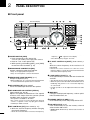
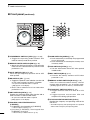
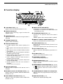
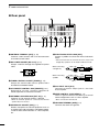
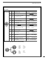
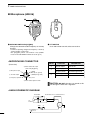
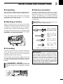
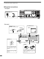
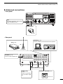
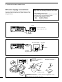
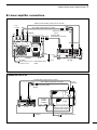
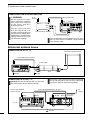
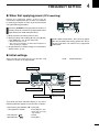
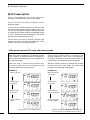
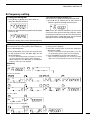
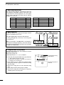
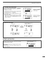
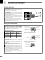
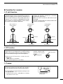
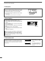
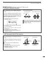
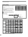
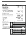
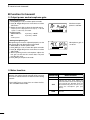
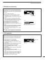
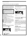
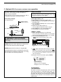
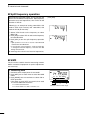
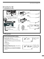

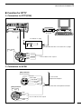

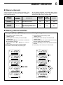
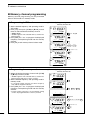
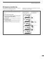
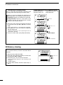
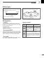
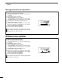
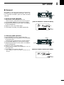
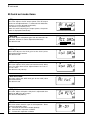
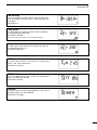
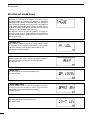
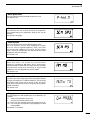
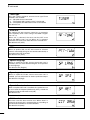
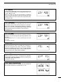
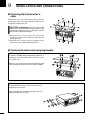
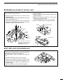
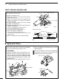

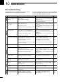
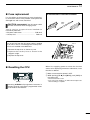
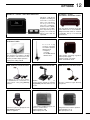

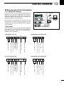
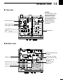
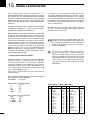
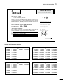

![v .] jCg _ 1l(_ `o,C..NN EinCOR `1_11E1](http://vs1.manualzilla.com/store/data/005961751_1-73960e1521729271050e00b8575619b8-150x150.png)