1
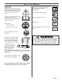
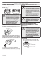
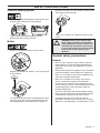
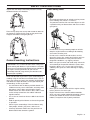
Operator’s manual
356BTX-series
Please read the operator’s manual carefully and make sure you understand the instructions
before using the machine.
English
INTRODUCTION
Dear customer!
Congratulations on your choice to buy a Husqvarna product! Husqvarna is based on a tradition that dates back to 1689,
when the Swedish King Karl XI ordered the construction of a factory on the banks of the Huskvarna River, for production
of muskets. The location was logical, since water power was harnessed from the Huskvarna River to create the waterpowered plant. During over 300 years of continuous operation, the Husqvarna factory has produced a lot of different
products, from wood stoves to modern kitchen appliances, sewing machines, bicycles, motorcycles etc. In 1956, the first
motor driven lawn mowers appeared, followed by chain saws in 1959, and it is within this area Husqvarna is working
today.
Today Husqvarna is one of the leading manufacturers in the world of forest and garden products, with quality as our
highest priority. We develop, manufacture and market high quality motor driven products for forestry and gardening as
well as for building and construction industry.
Your purchase gives you access to professional help with repairs and service whenever this may be necessary. If the
retailer who sells your machine is not one of our authorized dealers, ask for the address of your nearest servicing dealer.
It is our wish that you will be satisfied with your product and that it will be your companion for a long time. Think of this
operator′s manual as a valuable document. By following its′ content (using, service, maintenance etc) the life span and
the second-hand value of the machine can be extended. If you ever lend or sell this machine, make sure that the
borrower or buyer gets the operator′s manual, so they will also know how to properly maintain and use it.
Thank you for using a Husqvarna product.
Husqvarna AB has a policy of continuous product development and therefore reserves the right to modify the design and
appearance of products without prior notice.
For customer assistance, contact us at our website: www.usa.husqvarna.com
2 – English
KEY TO SYMBOLS
Symbols
WARNING! The machine can be a
dangerous tool if used incorrectly or
carelessly, which can cause serious
or fatal injury to the operator or
others.
Please read the operator’s manual
carefully and make sure you
understand the instructions before
using the machine.
Switch off the engine by moving the stop
switch to the STOP position before
carrying out any checks or
maintenance.
Always wear protective gloves.
Regular cleaning is required.
Visual check.
Always wear:
•
Hearing protection
•
Approved eye protection
Protective goggles or a visor must be
worn.
Gloves should be worn when
necessary.
The blower can forcibly throw
objects that can bounce back.
This can result in serious eye
injuries if the recommended
safety equipment is not used.
The blower operator
must make sure that no
bystanders or animals
come nearer than 15
metres. Whenever
several operators are working in the same work area, they
should maintain a safe distance of at least 15 metres from
one another.
The engine exhaust from this product
contains chemical known to the State
of California to cause cancer, birth
defects or other reproductive harm.
A breathing mask should be used
when there is a risk of dust.
Other symbols/decals on the machine refer to special
certification requirements for certain markets.
English – 3
CONTENTS
Contents
INTRODUCTION
Dear customer! .....................................................
KEY TO SYMBOLS
Symbols ................................................................
CONTENTS
Contents ...............................................................
Note the following before starting: ........................
SAFETY INSTRUCTIONS
Personal protective equipment .............................
Machine′s safety equipment .................................
Checking, maintaining and servicing the
machine′s safety equipment .................................
General safety precautions ...................................
General working instructions ................................
WHAT IS WHAT?
What is what on the blower? .................................
ASSEMBLY
Assembling the blow pipe and control handle .......
FUEL HANDLING
Fuel .......................................................................
Fueling ..................................................................
STARTING AND STOPPING
Star ting and stopping ............................................
MAINTENANCE
Carburetor .............................................................
Muffler ...................................................................
Cooling system .....................................................
Spark plug .............................................................
Air filter ..................................................................
Maintenance schedule ..........................................
TECHNICAL DATA
Technical data .......................................................
FEDERAL AND CALIFORNIA EMISSIONS
CONTROL WARRANTY STATEMENT
YOUR WARRANTY RIGHTS AND OBLIGATIONS
Note the following before
starting:
2
3
Please read the operator’s manual carefully.
!
4
4
5
5
!
6
7
9
12
16
WARNING! Under no circumstances may
the design of the machine be modified
without the permission of the
manufacturer. Always use genuine
accessories. Non-authorized
modifications and/or accessories can
result in serious personal injury or the
death of the operator or others.
Your warranty may not cover damage or
liability caused by the use of nonauthorized accessories or replacement
parts.
11
14
15
WARNING! Long-term exposure to noise
can result in permanent hearing
impairment. So always use approved
hearing protection.
!
WARNING! A blower is a dangerous tool
if used carelessly or incorrectly and can
cause serious, even fatal injuries. It is
extremely important that you read and
understand the contents of this
Operator’s manual.
17
17
18
18
18
20
21
22
The Emissions Compliance Period referred to on the
Emission Compliance label indicates the number of
operating hours for which the engine has been shown to
meet Federal and Californian emissions requirements.
Husqvarna AB has a policy of continuous product
development and therefore reserves the right to modify
the design and appearance of products without prior
notice.
The machine is only designed for blowing lawns,
pathways, asphalt roads and the like.
4 – English
SAFETY INSTRUCTIONS
Personal protective equipment
!
!
•
WARNING! You must use approved
personal protective equipment whenever
you use the machine. Personal protective
equipment cannot eliminate the risk of
injury but it will reduce the degree of
injury if an accident does happen. Ask
your dealer for help in choosing the right
equipment. Please read the operator’s
manual carefully and make sure you
understand the instructions before using
the machine.
WARNING! Listen out for warning signals
or shouts when you are wearing hearing
protection. Always remove your hearing
protection as soon as the engine stops.
•
Wear clothes made of a strong fabric and avoid loose
clothing that can catch on twigs and branches. Always
wear heavy, long pants. Do not wear jewellery, shorts
sandals or go barefoot. Secure hair so it is above
shoulder level.
•
A breathing mask should be used when there is a risk
of dust.
•
Always have a first aid kit nearby.
Gloves should be worn when necessary.
Machine′s safety equipment
•
Wear hearing protection that provides adequate noise
reduction.
This section describes the machine′s safety equipment,
its purpose, and how checks and maintenance should be
carried out to ensure that it operates correctly. See the
”What is what?” section to locate where this equipment is
positioned on your machine.
!
•
•
Always wear approved eye protection. If you use a
visor then you must also wear approved protective
goggles. Approved protective goggles must comply
with standard ANSI Z87.1 in the USA or EN 166 in EU
countries. Blows from branches or objects that are
thrown can damage the eyes.
WARNING! Never use a machine that has
faulty safety equipment! Carry out the
inspection, maintenance and service
routines listed in this section.
Stop switch
Use the stop switch to switch off the engine.
Wear sturdy, non-slip boots.
English – 5
SAFETY INSTRUCTIONS
Vibration damping system
Your machine is equipped with a vibration damping
system that is designed to reduce vibration and make
operation easier.
!
WARNING! Overexposure to vibration
can lead to circulatory damage or nerve
damage in people who have impaired
circulation. Contact your doctor if you
experience symptoms of overexposure
to vibration. Such symptoms include
numbness, loss of feeling, tingling,
pricking, pain, loss of strength, changes
in skin colour or condition. These
symptoms normally appear in the
fingers, hands or wrists. The risk
increases at low temperatures.
Muffler
The muffler is designed to keep noise levels to a minimum
and to direct exhaust fumes away from the user.
maintaining and servicing the machine’s safety
equipment.
!
!
6 – English
WARNING! The inside of the muffler
contain chemicals that may be
carcinogenic. Avoid contact with these
elements in the event of a damaged
muffler.
Checking, maintaining and
servicing the machine′s safety
equipment
WARNING! All servicing and repair work
on the machine requires special training.
This is especially true of the machine′s
safety equipment. If your machine fails
any of the checks described below you
must contact your service agent. When
you buy any of our products we
guarantee the availability of professional
repairs and service. If the retailer who
sells your machine is not a servicing
dealer, ask him for the address of your
nearest service agent.
Stop switch
•
For mufflers it is very important that you follow the
instructions on checking, maintaining and servicing your
machine. See instructions under the heading Checking,
Bear in mind that: Engine exhaust fumes
contain carbon monoxide, which can
cause carbon monoxide poisoning. For
this reason you should not start or run
the machine indoors, or anywhere that is
poorly ventilated.
The exhaust fumes from the engine are
hot and may contain sparks which can
start a fire. Never start the machine
indoors or near combustible material!
!
In countries that have a warm and dry climate there is a
significant risk of fire. Consequently, we have equipped
the muffler with a spark arrestor screen mounted inside
the muffler.
WARNING!
Start the engine and make sure the engine stops
when you move the stop switch to the stop setting.
SAFETY INSTRUCTIONS
Vibration damping system
•
Check the vibration damping units regularly for cracks
or deformation. Replace them if damaged.
•
Check that the vibration damping element is
undamaged and securely attached.
blocked screen will cause the engine to overheat and
may lead to serious damage.
•
Muffler
•
Never use a muffler with a defective spark arrestor
screen.
!
Never use a machine that has a faulty muffler.
WARNING! Never use a machine with
faulty safety equipment. The machine’s
safety equipment must be checked and
maintained as described in this section.
If your machine fails any of these checks
contact your service agent to get it
repaired.
General safety precautions
General
•
•
Regularly check that the muffler is securely attached
to the machine.
The muffler on your machine is equipped with a spark
arrestor screen; this must be cleaned regularly. See
the heading Muffler in the Maintenance chapter. A
•
Never use the machine if you are tired, if you have
drunk alcohol, or if you are taking medication that
could affect your vision, your judgement or your coordination.
•
Wear personal protective equipment. See instructions
under the heading ”Personal protective equipment”.
•
Never use a machine that has been modified in any
way from its original specification.
•
Never use a machine that is faulty. Carry out the
checks, maintenance and service instructions
described in this manual. Some maintenance and
service measures must be carried out by trained and
qualified specialists. See instructions under the
heading Maintenance.
•
All covers and guards must be fitted before starting.
Ensure that the spark plug cap and ignition lead are
undamaged to avoid the risk of electric shock.
•
The blower operator must make sure that no
bystanders or animals come nearer than 15 metres.
Whenever several operators are working in the same
English – 7
SAFETY INSTRUCTIONS
work area, they should maintain a safe distance of at
least 15 metres from one another.
!
WARNING! This machine produces an
electromagnetic field during operation.
This field may under some
circumstances interfere with active or
passive medical implants. To reduce the
risk of serious or fatal injury, we
recommend persons with medical
implants to consult their physician and
the medical implant manufacturer before
operating this machine.
•
Never start the machine:
- If you have spilled fuel on it. Wipe off the spillage and
allow remaining fuel to evaporate.
- If you have spilled fuel on yourself or your clothes,
change your clothes. Wash any part of your body that has
come in contact with fuel. Use soap and water.
- If the machine is leaking fuel. Check regularly for leaks
from the fuel cap and fuel lines.
Transport and storage
•
Store and transport the machine and fuel so that there
is no risk of any leakage or fumes coming into contact
with sparks or naked flames, for example, from
electrical machinery, electric motors, electrical relays/
switches or boilers.
Starting
•
Never start the machine indoors. Exhaust fumes can
be dangerous if inhaled.
•
•
Observe the surroundings and ensure that no people
or animals can come into contact with the blower.
When storing and transporting fuel always use
approved containers intended for this purpose.
•
•
Place the machine on the ground, press the machine
body against the ground with your left hand (NOTE!
Not your foot). Now grasp the starter handle with your
right hand and then pull quickly and firmly.
When storing the machine for long periods the fuel
tank must be emptied. Contact your local gas station
to find out where to dispose of excess fuel.
•
Ensure the machine is cleaned and that a complete
service is carried out before long-term storage.
•
Secure the machine during transport.
!
WARNING! Take care when handling fuel.
Bear in mind the risk of fire, explosion
and inhaling fumes.
Adjusting the harness
!
Fuel safety
•
Always use a fuel container with an anti-spill valve.
•
Never refuel the machine while the engine is running.
Always stop the engine and let it cool for a few minutes
before refuelling.
•
Make sure there is plenty of ventilation when refuelling
or mixing fuel (gasoline and 2-stroke oil).
•
Avoid all skin contact with fuel. Fuel is a skin irritant
and may even cause skin changes.
•
Move the machine at least 10 ft (3 m) from the
refuelling point before starting it.
8 – English
WARNING! The harness must always be
worn when working with the machine.
Failure to do so means you will be unable
to manoeuvre safely and this can result
in injury to yourself or others.
A correctly adjusted harness and machine significantly
facilitates the work. Adjust the harness to give the best
working position.
SAFETY INSTRUCTIONS
Tighten the side straps so that the pressure is evenly
distributed across the shoulders.
Basic safety rules
•
No unauthorised persons or animals may be present
in the working area, which is 15 metres.
•
The powerful currents of air can move objects at such
a speed that they can bounce back and cause serious
eye injuries.
•
Do not direct the air jet towards people or animals.
•
Stop the engine before assembling or dismantling
accessories or other parts.
•
Do not use the machine in bad weather, such as
dense fog, heavy rain, strong wind, intense cold, etc.
Working in bad weather is tiring and can lead to
dangerous conditions, e.g. slippery surfaces.
•
Make sure you can move and stand safely. Check the
area around you for possible obstacles (roots, rocks,
branches, ditches, etc.) in case you have to move
suddenly. Take great care when working on sloping
ground.
•
Never put the machine down with the engine running
unless you have it in clear sight.
•
Engine exhaust fumes contain carbon monoxide,
which can cause carbon monoxide poisoning. For this
reason you should not start or run the machine
indoors, or anywhere that is poorly ventilated.
Place the hip strap over the hip and not too far down on
the stomach. Tighten the hip strap so that you feel the
weight of the blower resting on your hip.
General working instructions
IMPORTANT! This section considers basic safety rules
when working with blowers. If you encounter a situation
where you are uncertain how to proceed you should ask
an expert. Contact your dealer or your service
workshop. Avoid all usage which you consider to be
beyond your capability.
Show consideration to persons in your surroundings by
avoiding using the machine at unsuitable times, such as
late in the evening or early in the morning. Read through
and follow the simple directions so that you disturb your
surroundings as little as possible.
•
Use the blower with the lowest possible throttle. It is
seldom necessary to use full throttle, and many work
procedures can be done at half throttle. A lower
throttle means less noise and less dust, and it is also
easier to keep control over the rubbish collected
together/moved.
•
Use a rake or a brush to release rubbish stuck to the
ground.
•
Hold the opening of the blower as close to the ground
as possible.
•
Observe your surroundings. Direct the blower away
from people, animals, play areas, and cars etc.
•
Clean up afterwards. Make sure that you have not
blown rubbish into someone’s garden.
English – 9
SAFETY INSTRUCTIONS
•
The blower must not be used while on a ladder or
scaffolding.
•
CAUTION! Do not use the machine unless you are
able to call for help in the event of an accident.
engine’s working temperature, which can result in
engine failure. Stop the engine and remove the object.
Basic working techniques
!
!
WARNING! Watch out for thrown objects.
Always wear eye protection. Stones,
rubbish, etc. can be thrown up into the
eyes causing blindness or serious injury.
Keep unauthorised persons at a
distance. Children, animals, onlookers
and helpers should be kept outside the
safety zone of 15 m. Stop the machine
immediately if anyone approaches.
WARNING! Always stop the engine
before cleaning.
•
The speed of the air jet is regulated by means of the
throttle. Select the speed best suited for respective
tasks. You can set the throttle position using the ”stop
switch” and by doing so not need to hold your finger
on the throttle all the time you are using the blower.
Full throttle is obtained when the control is held back
fully.
•
Check that the air intake is not blocked, for example,
by leaves or rubbish. A clogged air intake reduces the
machine’s blowing capacity and increases the
10 – English
•
Be aware of the wind direction. Work with the wind to
make your work easier.
•
Using the blower to move large piles is time
consuming and creates unnecessary noise.
•
When work is finished the machine should be stored
vertically.
WHAT IS WHAT?
What is what on the blower?
1
Outer cover
12 Muffler
2
Harness
13 Spark plug
3
Outlet pipe
14 Air purge
4
Bellows with guard
15 Choke control
5
Stop switch with throttle position setting
16 Fuel tank
6
Control handle/Operating handle
17 Adjuster screws carburetor
7
Throttle control
18 Air filter
8
Control pipe
19 Combination spanner
9
Intermediate pipe
20 Handlebar (Accessory)
10 Blow pipe
21 Flat nozzle (Accessory)
11 Starter handle
22 Operator’s manual
English – 11
ASSEMBLY
Assembling the blow pipe and
control handle
•
•
•
•
Refit the bolts and tighten well. Check that the control
pipe is in the right position and can rotate equally in
both directions.
•
Disassemble the knob from the control handle and
push the holder on to the control pipe.
•
Assemble the knob and adjust position and angle to
achieve comfortable working position, tighten the
knob. Attach the cabling in the cover.
Loosen the two screws on the fan’s outlet pipe and
remove the two wear ring halves located on the outlet
pipe.
Place these on the pipe bend so that the guide on the
wear ring halves aligns with the slot on the pipe bend.
Refit the pipe bend with the wear halves in the fan’s
outlet pipe. Make sure the holes in the wear ring
halves align with the screws that are used to secure
the halves in the pipe bend.
Connect the intermediate pipe and air nozzle. Push the
pipes together and turn them so they lock in relation to
one another.
•
Also pay attention to the stops located on the pipe
bend and the fan’s outlet pipe. Ensure that the stop on
the pipe bend comes in front of the stop on the outlet
pipe.
12 – English
ASSEMBLY
Accessories
Handlebar
Disassemble the intermediate pipe. Disassemble the
knob from the holder and puch the holder on to the holder
pipe. Assemble the knob and tighten.
Assemble the intermediate pipe.
Flat nozzle
•
If higher air speed is required, the round blow pipe is
replaced by the flat nozzle.
English – 13
FUEL HANDLING
Fuel
Gasoline, litre
CAUTION! The machine is equipped with a two-stroke
engine and must always been run using a mixture of
gasoline and two-stroke engine oil. It is important to
accurately measure the amount of oil to be mixed to
ensure that the correct mixture is obtained. When mixing
small amounts of fuel, even small inaccuracies can
drastically affect the ratio of the mixture.
!
WARNING! Always ensure there is
adequate ventilation when handling fuel.
Gasoline
Two-stroke oil, litre
2% (1:50)
5
0,10
10
0,43/0,20
15
0,30
20
0,40
US gallon
US fl. oz.
1
2 1/2
2 1/2
6 1/2
5
12 7/8
Mixing
•
Always mix the gasoline and oil in a clean container
intended for fuel.
•
Always start by filling half the amount of the gasoline
to be used. Then add the entire amount of oil. Mix
(shake) the fuel mixture. Add the remaining amount of
gasoline.
•
Mix (shake) the fuel mixture thoroughly before filling
the machine’s fuel tank.
•
Do not mix more than one month’s supply of fuel at a
time.
Two-stroke oil
•
If the machine is not used for some time the fuel tank
should be emptied and cleaned.
•
For best results and performance use HUSQVARNA
two-stroke oil, which is specially formulated for our
two-stroke engines. Mixture 1:50 (2%).
•
This engine is certified to operate on unleaded
gasoline.
•
If HUSQVARNA two-stroke oil is not available, you
may use another two-stroke oil of good quality that is
intended for air cooled engines. Contact your dealer
when selecting an oil.
•
Never use two-stroke oil intended for water-cooled
outboard engines, sometimes referred to as outboard
oil.
•
Never use oil intended for four-stroke engines.
CAUTION! Always use high grade oil mixed gasoline
(minimum 87 RON).
•
This engine is certified to operate on unleaded
gasoline.
•
The lowest recommended octane rating is 87. If you
run the engine on lower octane rating than 87 socalled “knocking“ can occur. This leads to an
increased engine temperature, which can result in a
serious engine breakdown.
•
When working at continuous high revs a higher octane
rating is recommended.
14 – English
FUEL HANDLING
Fueling
!
WARNING! Taking the following
precautions, will lessen the risk of fire:
Do not smoke or place hot objects near
fuel.
Always shut off the engine before
refuelling.
Always stop the engine and let it cool for
a few minutes before refuelling.
When refuelling, open the fuel cap slowly
so that any excess pressure is released
gently.
Tighten the fuel cap carefully after
refuelling.
Always move the machine away from the
refuelling area before starting.
•
Move the machine at least 10 ft (3 m) from the
refuelling point before starting it.
•
Clean the area around the fuel cap. Contamination in
the tank can cause operating problems.
•
Ensure that the fuel is well mixed by shaking the
container before filling the tank.
English – 15
STARTING AND STOPPING
Starting and stopping
!
Primer bulb: Press the air purge repeatedly until fuel
begins to fill the bulb. The bulb need not be completely
filled.
WARNING! Always move the machine
away from the refuelling area before
starting. Place the machine on a flat
surface.
Make sure no unauthorised persons are
in the working area, otherwise there is a
risk of serious personal injury. The safety
distance is 15 metres.
The machine may only be started in its
complete design. If the machine is
started without all the guards fitted there
is a risk of personal injuries.
Cold engine
Ignition: Set the stop switch to the start position.
Start position is achieved by moving the stop switch
slightly backwards until the stop switch clicks into start
position.
Warm engine
Use the same starting procedure as for a cold engine but
without setting the choke control in the choke position.
Starting
Hold the body of the machine on the ground using your
left hand (CAUTION! Not with your foot!). Grip the starter
handle, slowly pull out the cord with your right hand until
you feel some resistance (the starter pawls grip), now
quickly and powerfully pull the cord.
It is not allowed to set the stop switch in full throttle
position.
Choke: Set the choke control in the choke position.
Never wrap the starter cord around your hand
Repeat pulling the cord until the engine starts. When the
engine starts, return choke control to run position.
CAUTION! Do not pull the starter cord all the way out and
do not let go of the starter handle when the cord is fully
extended. This can damage the machine.
Stopping
The engine is stopped by moving the stop switch to the
stop position.
16 – English
MAINTENANCE
Carburetor
Adjustment of the idle speed
Your Husqvarna product has been designed and
manufactured to specifications that reduce harmful
emissions. After the engine has used 8-10 tanks of fuel
the engine will be run-in. To ensure that it continues to run
at peak performance and to minimise harmful exhaust
emissions after the running-in period, ask your dealer/
service workshop (who will have a rev counter at their
disposal) to adjust your carburettor.
Before any adjustments are made, make sure that the air
filter is clean and the air filter cover is fitted.
Adjust the idle speed screew T clockwise respectively
anti-clockwise until an idle speed of 2300 rpm is reached.
Function
The carburetor governs the engine’s speed via the throttle
control. Air and fuel are mixed in the carburetor. The air/
fuel mixture is adjustable. Correct adjustment is essential
to get the best performance from the machine.
The setting of the carburetor means that the engine is
adapted to local conditions, for example, the climate,
altitude, fuel and the type of 2-stroke oil.
The carburetor has three adjustment controls:
•
L = Low speed jet
•
H = High speed jet
•
T = Idle adjustment screw
L
Muffler
The muffler is designed to reduce the noise level and to
direct the exhaust gases away from the operator. The
exhaust gases are hot and can contain sparks, which may
cause fire if directed against dry and combustible
material.
T
H
The L and H-jets are used to adjust the supply of fuel to
match the rate that air is admitted, which is controlled with
the throttle. If they are screwed clockwise the air/fuel ratio
becomes leaner (less fuel) and if they are turned anticlockwise the ratio becomes richer (more fuel). A lean
mixture gives a higher engine speed and a rich mixture
gives a lower engine speed.
The T-screw regulates the throttle setting at idle speed. If
the T-screw is turned clockwise this gives a higher idle
speed; turning it anti-clockwise gives a lower idle speed.
The muffler is equipped with a special spark arrestor
screen. The spark arrestor screen should be cleaned
once a month. This is best done with a wire brush.
To remove the spark arrestor screen proceed as follows:
Remove the screws to the capillary tube and exhaust
pipe.
Basic setting
The basic carburetor settings are adjusted during testing
at the factory. The basic setting is richer than the optimal
setting and should be maintained for the first few hours
the machine is in use. The carburettor should then be
finely adjusted. Fine adjustment should be carried out by
a skilled technician.
English – 17
MAINTENANCE
Loosen the muffler’s 2 screws and remove the muffler.
5
Emergency cooling nozzle
Clean the cooling system with a brush once a week, more
often in demanding conditions. A dirty or blocked cooling
system results in the machine overheating which causes
damage to the piston and cylinder. Check that the nozzles
are not blocked.
Spark plug
Pull out the spark arrestor screen and clean using a wire
brush. Replace the spark arrestor screen if it is defective.
The spark plug condition is influenced by:
•
Incorrect carburetor adjustment.
•
An incorrect fuel mixture (too much or incorrect type
of oil).
•
A dirty air filter.
These factors cause deposits on the spark plug
electrodes, which may result in operating problems and
starting difficulties.
CAUTION! Never use a machine with a defective muffler.
!
WARNING! The muffler gets very hot
during use and remain so for some time
after stopping. This also applies at idle
speed. Contact can result in burns to the
skin. Remember the risk of fire!
If the machine is low on power, difficult to start or runs
poorly at idle speed: always check the spark plug first
before taking any further action. If the spark plug is dirty,
clean it and check that the electrode gap is 0.020 inch (0.5
mm). The spark plug should be replaced after about a
month in operation or earlier if necessary.
Cooling system
To keep the working temperature as low as possible the
machine is equipped with a cooling system.
The cooling system consists of:
4
1
Air filter
The air filter must be regularly cleaned to remove dust
and dirt in order to avoid:
2
3
5
1
Air intake on the underside of the blower.
2
Nozzle for cooling the cylinder
3
Cooling fins on the cylinder.
4
Cooling air conductor (directs cold air over the
cylinder).
18 – English
CAUTION! Always use the recommended spark plug
type! Use of the wrong spark plug can damage the piston/
cylinder.
•
Carburettor malfunctions
•
Starting problems
•
Loss of engine power
•
Unnecessary wear to engine parts
•
Excessive fuel consumption.
MAINTENANCE
Clean the filter every 40 hours, or more regularly if
conditions are exceptionally dusty.
The air filter is fitted in the air filter cowling.
Ensure that the filter is soaked in oil before refitting it.
Avoid contact with hot surfaces on muffler, cylinder etc.
Contact can result in burns to the skin.
Cleaning the air filter
Dismantle the outer cover with the help of the four
fasteners holding the outer cover.
An air filter that has been in use for a long time cannot be
cleaned completely. The filter must therefore be replaced
with a new one at regular intervals. A damaged air filter
must always be replaced.
Oiling the air filter
Always use HUSQVARNA filter oil, art. no. 531 00 60-76.
The filter oil contains a solvent to make it spread evenly
through the filter. You should therefore avoid skin contact.
Loosen the two fasteners holding the air filter cowling and
remove the filter. Wash the filter clean in warm, soapy
water.
Put the filter in a plastic bag and pour the filter oil over it.
Knead the plastic bag to distribute the oil. Squeeze the
excess oil out of the filter inside the plastic bag and pour
off the excess before fitting the filter to the machine. Never
use common engine oil. This would drain through the filter
quite quickly and collect in the bottom.
English – 19
MAINTENANCE
Maintenance schedule
Below you will find some general maintenance
instructions. If you need further information please
contact your service workshop.
Daily maintenance
1
Clean the outside of the machine.
2
Check that the throttle control functions safely.
3
Check that the stop switch works correctly.
4
Check that nuts and screws are tight.
5
Check that there are no fuel leaks.
Weekly maintenance
1
Clean the air filter. Replace if necessary.
2
Clean the outside of the spark plug. Remove and
check the electrode gap. Adjust the gap to 0.5 mm or
change the spark plug.
3
Clean the cooling system.
Monthly maintenance
1
Check fuel hose for cracks or other damage. Change
if necessary.
2
Check all cables and connections.
3
Replace the spark plug. Check that the spark plug is
fitted with a suppressor.
4
Check and clean the spark arrestor screen on the
muffler.
5
Check that the vibration damping elements are not
damaged.
6
Clean the fuel tank.
IMPORTANT!
Use only HUSQVARNA replacement parts. Use of other
brands of replacement parts can cause damage to your
unit or injury to the operator or others. Your warranty does
not cover damage or liability caused by the use of
accessories and/or attachments not specifically
recommended by HUSQVARNA.
20 – English
TECHNICAL DATA
Technical data
Technical data
356BTx
Motor
Cylinder displacement, cu.in/cm3
3,15/51,7
Cylinder bore, inch/mm
44
Stroke, inch/mm
34
Idle speed, rpm
2300
Max. engine output, acc. to ISO 8893, kW/ rpm
2,4/6000
Catalytic converter muffler
No
Ignition system
Spark plug
NGK BPMR 7A
Electrode gap, inch/mm
0,02/0,5
Fuel and lubrication system
Fuel tank capacity, US pint/litre
1,5
Weight
Weight without fuel, Lbs/kg
22,9/10,4
Sound levels
Sound level measured at 50 ft (15m) per ANSI B175.2, dB (A)
64
Sound levels
(see note 1)
Equivalent sound pressure level at the operator’s ear, measured
according to EN15503 dB(A)
91
Vibration levels
(see note 2)
Vibration levels at handles, measured according to EN/ISO 11806 and
ISO 7916, m/s2
3,9
Fan performance
Max. air velocity vith standard nozzle, m/s:
79
Air flow with standard nozzle, m3/min
13,3
Max air velocity with flat nozzle (Accessory), m/s:
90
Air flow with flat nozzle (accessory), m3/min:
13,0
Note 1: The equivalent sound pressure level value is calculated with a work cycle of a duration of 1/7 for idling and 6/7
for racing. Reported data for equivalent sound pressure level for the machine has a typical statistical dispersion
(standard deviation) of 1 dB(A).
Note 2: The equivalent vibration level value is calculated with a work cycle of a duration of 1/7 for idling and 6/7 for racing.
Reported data for equivalent vibration level has a typical statistical dispersion (standard deviation) of 1 m/s2.
English – 21
FEDERAL AND CALIFORNIA EMISSIONS CONTROL WARRANTY STATEMENT
YOUR WARRANTY RIGHTS AND
OBLIGATIONS
The EPA (U.S. Environmental Protection Agency), CARB
(California Air Resources Board), Environment Canada
and Husqvarna Forest & Garden are pleased to explain
the emissions control system’s warranty on your 2009 and
later small off-road engine. In U.S. and Canada, new
equipment that use small off-road engines must be
designed, built, and equipped to meet the applicable
Federal or Californian stringent anti-smog standards.
Husqvarna Forest & Garden must warrant the emissions
control system on your small off-road engine for the
period listed below provided there has been no abuse,
neglect or improper maintenance of your equipment. Your
emissions control system may include parts such as the
carburetor, ignition system, catalytic converter, fuel tank,
filters and other associated components. Also, included
may be hoses, belts, connectors, sensors, and other
emission-related assemblies. Where a warrantable
condition exists, Husqvarna Forest & Garden will repair
your small off-road engine at no cost to you including
diagnosis, parts and labor.
MANUFACTURER′S WARRANTY
COVERAGE
The emissions control system is warranted for two years.
If any emissions-related part on your equipment is
defective, the part will be repaired or replaced by
Husqvarna Forest & Garden.
OWNER′S WARRANTY
RESPONSIBILITIES
•
As the small off-road engine owner, you are
responsible for performance of the required
maintenance listed in your operator’s manual.
Husqvarna Forest & Garden recommends that you
retain all receipts covering maintenance on your small
off-road engine, but Husqvarna Forest & Garden
cannot deny warranty solely for the lack of receipts or
your failure to ensure the performance of all
scheduled maintenance.
•
As the small off-road engine owner, you should
however be aware that Husqvarna Forest & Garden
may deny you warranty coverage if your small off-road
engine or a part has failed due to abuse, neglect, or
improper maintenance or unapproved modifications.
•
You are responsible for presenting your small off-road
engine to a Husqvarna Forest & Garden distribution
center or service center as soon as the problem
exists. The warranty repairs should be completed in a
reasonable amount of time, not to exceed 30 days. If
you have any questions regarding your warranty
coverage, you should contact Husqvarna Forest &
Garden at 1-800-487-5951 or visit
www.usa.husqvarna.com.
22 – English
WARRANTY COMMENCEMENT DATE
The warranty period begins on the date the engine or
equipment is delivered to an ultimate purchaser.
LENGTH OF COVERAGE
Husqvarna Forest & Garden warrants to the ultimate
purchaser and each subsequent owner that the engine or
equipment is designed, built, and equipped so as to
conform with all applicable regulations adopted by EPA
and CARB, and is free from defects in materials and
workmanship that causes the failure of a warranted part
for a period of two years.
WHAT IS COVERED
REPAIR OR REPLACEMENT OF PARTS Repair or
replacement of any warranted part under the warranty
must be performed at no charge to the owner at a
warranty station. Warranty services or repairs will be
provided at all Husqvarna Forest & Garden distribution
centers that are franchised to service the subject engines.
Throughout the emissions warranty period of two years,
Husqvarna Forest & Garden must maintain a supply of
warranted parts sufficient to meet the expected demand
for such parts.
WARRANTY PERIOD Any warranted part that is
scheduled for replacement as required in the
maintenance schedule, is warranted for the period of time
prior to the first scheduled replacement point for that part.
If the part fails prior to the first scheduled replacement,
the part will be repaired or replaced by Husqvarna Forest
& Garden at no cost. Any such part repaired or replaced
under warranty is warranted for the remainder of the
period prior to the first scheduled replacement point for
the part. Any warranted part that is not scheduled for
replacement as required in the maintenance schedule, is
warranted for two years. If any such part fails during the
period of warranty coverage, it will be repaired and
replaced by Husqvarna Forest & Garden at no cost. Any
such part repaired or replaced under the warranty is
warranted for the remaining warranty period. Any
warranted part that is scheduled only for regular
inspection in the maintenance schedule will be warranted
for a period of two years. A statement in such written
instructions to the effect of ”repair or replace as
necessary” will not reduce the period of warranty
coverage. Any such part repaired or replaced under
warranty will be warranted for the remaining warranty
period.
DIAGNOSIS The owner must not be charged for
diagnostic labor that leads to the determination that a
warranted part is in fact defective, provided that such
diagnostic work is performed at a warranty station.
CONSEQUENTIAL DAMAGES Husqvarna Forest &
Garden is liable for damages to other engine components
proximately caused by a failure under warranty of any
warranted part.
FEDERAL AND CALIFORNIA EMISSIONS CONTROL WARRANTY STATEMENT
EMISSION WARRANTY PARTS LIST
1
Carburetor and internal parts
2
Intake pipe, airfilter holder and carburetor bolts.
3
Airfilter and fuelfilter covered up to maintenance
schedule.
4
Spark Plug, covered up to maintenance schedule
5
Ignition Module
6
Muffler with catalytic converter
7
Fuel tank
WHAT IS NOT COVERED
All failures caused by abuse, neglect or improper
maintenance are not covered.
ADD -ON OR MODIFIED PARTS
Add-on or modified parts that are not exempted by CARB
or EPA may not be used. The use of any non-exempted
add-on or modified parts will be grounds for disallowing a
warranty claim. Husqvarna Forest & Garden will not be
liable to warrant failures of warranted parts caused by the
use of a non-exempted add-on or modified part.
HOW TO FILE A CLAIM
If you have any questions regarding your warranty rights
and responsibilities, you should contact your nearest
authorized servicing dealer or call Husqvarna Forest &
Garden at 1-800-487-5951 or visit
www.usa.husqvarna.com.
WHERE TO GET WARRANTY SERVICE
Warranty services or repairs are provided through all
Husqvarna Forest & Garden authorized servicing dealers.
MAINTENANCE, REPLACEMENT AND
REPAIR OF EMISSION-RELATED PARTS
Any replacement part may be used in the performance of
any warranty maintenance or repairs and must be
provided without charge to the owner. Such use will not
reduce the warranty obligations of the manufacturer.
MAINTENANCE STATEMENT
The owner is responsible for the performance of all
required maintenance, as defined in the operator’s
manual.
English – 23
Original instructions
1153191-95
´®z+U33¶5]¨
´®z+U33¶5]¨
2010-05-20