1
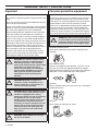
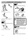
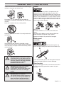
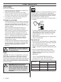
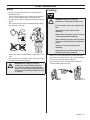
Operator′s manual
327HDA65X-series
327HE3X-series 327HE4X-series
Please read the operator’s manual carefully and make sure you understand the instructions
before using the machine.
English
KEY TO SYMBOLS
Symbols
WARNING! Incorrect or careless
use of a hedge trimmer can turn it
into a dangerous tool that can cause
serious or even fatal injury. It is
extremely important that you read
and understand the contents of this
operator’s manual.
Please read the operator’s manual
carefully and make sure you
understand the instructions before
using the machine.
Always wear:
•
Approved hearing protection
•
Approved eye protection
This product is in accordance with
applicable EC directives.
Cutting tool. Do not touch the tool
without first switching off the
engine.
This machine is not electrically
insulated. If the machine
touches or comes close to highvoltage power lines it could lead
to death or serious bodily injury.
Electricity can jump from one
point to another by arcing. The
higher the voltage, the greater
the distance electricity can
jump. Electricity can also travel
through branches and other
objects, especially if they are
wet. Always keep a distance of at least 10 m between the
machine and high-voltage power lines and/or any objects
that are touching them. If have to work within this safe
distance you should always contact the relevant power
company to make sure the power is switched off before
you start work.
This machine can be dangerous! The operator of the
machine must ensure, while working, that no persons or
animals come closer than 15 metres.
Arrows which show limits for handle
positioning.
2 – English
Always wear approved protective
gloves.
Wear sturdy, non-slip boots or shoes.
Noise emission to the environment
according to the European
Community’s Directive. The
machine’s emission is specified in
chapter Technical data and on label.
Other symbols/decals on the machine refer to special
certification requirements for certain markets.
The engine is switched off by moving
the stop switch to the stop position.
CAUTION! The stop switch
automatically returns to the start
position. In order to prevent
unintentional starting, the spark plug
cap must be removed from the spark plug when
assembling, checking and/or performing maintenance.
Always wear approved protective
gloves.
Regular cleaning is required.
Visual check.
Protective goggles or a visor must be
worn.
CONTENTS
Contents
KEY TO SYMBOLS
Symbols ................................................................
CONTENTS
Contents ...............................................................
Note the following before starting: ........................
INTRODUCTION
Dear Customer, ....................................................
WHAT IS WHAT?
What is what? .......................................................
GENERAL SAFETY PRECAUTIONS
Impor tant ..............................................................
Personal protective equipment .............................
Machine′s safety equipment .................................
ASSEMBLY
Fitting the hand guard and loop handle ................
Fitting the handle ..................................................
Fitting the cutting head .........................................
Adjusting the harness ...........................................
Fitting the impact guard ........................................
FUEL HANDLING
Fuel safety ............................................................
Fuel ......................................................................
Fuelling .................................................................
STARTING AND STOPPING
Check before starting ...........................................
Starting and stopping ...........................................
WORKING TECHNIQUES
General working instructions ................................
Transport position .................................................
MAINTENANCE
Carburettor ...........................................................
Muffler ..................................................................
Cooling system .....................................................
Spark plug ............................................................
Air filter .................................................................
Gear housing ........................................................
Cleaning and lubrication .......................................
Maintenance schedule .........................................
TECHNICAL DATA
Technical data ......................................................
EC-declaration of conformity ................................
Note the following before
starting:
2
3
3
Please read the operator’s manual carefully.
!
4
5
!
6
6
7
10
10
10
11
11
!
WARNING! Long-term exposure to noise
can result in permanent hearing
impairment. So always use approved
hearing protection.
WARNING! Under no circumstances may
the design of the machine be modified
without the permission of the
manufacturer. Always use genuine
accessories. Non-authorized
modifications and/or accessories can
result in serious personal injury or the
death of the operator or others.
WARNING! Incorrect or careless use of a
hedge trimmer can turn it into a
dangerous tool that can cause serious or
even fatal injury. It is extremely important
that you read and understand the
contents of this operator’s manual.
12
12
13
14
14
16
18
19
19
20
20
21
21
22
23
24
25
English – 3
INTRODUCTION
Dear Customer,
Congratulations on your choice to buy a Husqvarna product! Husqvarna is based on a tradition that dates back to 1689,
when the Swedish King Karl XI ordered the construction of a factory on the banks of the Husqvarna River, for production
of muskets. The location was logical, since water power was harnessed from the Huskvarna River to create the waterpowered plant. During the more than 300 years of beeing, the Husqvarna factory has produced a lot of different products,
from wood stoves to modern kitchen appliances, sewing machines, bicycles, motorcycles etc. In 1956, the first motor
driven lawn mowers appeared, followed by chain saws in 1959, and it is within this area Husqvarna is working today.
Today Husqvarna is one of the leading manufacturers in the world of forest and garden products, with quality as our
highest priority. The business concept is to develop, manufacture and market motor driven products for forestry and
gardening as well as for building and construction industry. Husqvarna′s aim is also to be in the front edge according to
ergonomics, usability, security and environmental protection. That is the reason why we have developed many different
features to provide our products within these areas.
We are convinced that you will appreciate with great satisfaction the quality and performance of our product for a very
long time to come. The purchase of one of our products gives you access to professional help with repairs and service
whenever this may be necessary. If the retailer who sells your machine is not one of our authorised dealers, ask for the
address of your nearest service workshop.
It is our wish that you will be satisfied with your product and that it will be your companion for a long time. Think of this
operator′s manual as a valuable document. By following its′ content (using, service, maintenance etc) the life span and
the second-hand value of the machine can be extended. If you will sell this machine, make sure that the buyer will get
the operator′s manual.
Thank you for using a Husqvarna product.
Husqvarna AB has a policy of continuous product development and therefore reserves the right to modify the design and
appearance of products without prior notice.
4 – English
WHAT IS WHAT?
327HE4
327HDA65
What is what?
1
Cutter
16 Air purge
2
Grease nipple and plug for filling lubricant.
17 Air filter cover
3
Bevel gear
18 Clutch cover
4
Blade guard (327HDA65)
19 Hand guard mounting screw (327HDA65, 327HE3)
5
Shaft
20 Angle adjustment handle (327HE3, 327HE4)
6
Front handle (327HDA65, 327HE3)
21 Angle adjustment knob
7
Front handle (327HE4)
22 Hand guard (327HDA65, 327HE3)
8
Throttle control
23 Combination spanner
9
Stop switch
24 Operator′s manual
10 Throttle lock
25 Transport guard
11 Harness support hook (327HE4)
26 Allen key
12 Cylinder cover
27 Harness (327HE4)
13 Starter handle
28 Impact guard (327HE4)
14 Fuel tank
29 Spark plug cap and spark plug
15 Choke control
English – 5
GENERAL SAFETY PRECAUTIONS
Important
Personal protective equipment
IMPORTANT!
IMPORTANT!
The machine is only designed for cutting branches and
twigs.
Incorrect or careless use of a hedge trimmer can turn it
into a dangerous tool that can cause serious or even
fatal injury. It is extremely important that you read and
understand the contents of this operator’s manual.
Never use a machine that has been modified in any way
from its original specification.
Never use the machine if you are tired, if you have drunk
alcohol, or if you are taking medication that could affect
your vision, your judgement or your co-ordination.
Wear personal protective equipment. See instructions
under the heading ”Personal protective equipment”.
Never use the machine in extreme weather conditions
such as severe cold, very hot and/or humid climates.
Never use a machine that is faulty. Carry out the checks,
maintenance and service instructions described in this
manual. Some maintenance and service measures
must be carried out by trained and qualified specialists.
See instructions under the heading Maintenance.
All covers and guards must be fitted before starting.
Ensure that the spark plug cap and ignition lead are
undamaged to avoid the risk of electric shock.
!
!
!
!
6 – English
WARNING! The ignition system of this
machine produces an electromagnetic
field during operation. This field may
under some circumstances interfere with
pacemakers. To reduce the risk of
serious or fatal injury, we recommend
persons with pacemakers to consult
their physician and the pacemaker
manufacturer before operating this
machine.
You must use approved personal protective equipment
whenever you use the machine. Personal protective
equipment cannot eliminate the risk of injury but it will
reduce the degree of injury if an accident does happen.
Ask your dealer for help in choosing the right equipment.
!
HEARING PROTECTION
Wear hearing protection that provides adequate noise
reduction.
EYE PROTECTION
Always wear approved eye protection. If you use a visor
then you must also wear approved protective goggles.
Approved protective goggles must comply with standard
ANSI Z87.1 in the USA or EN 166 in EU countries.
WARNING! Running an engine in a
confined or badly ventilated area can
result in death due to asphyxiation or
carbon monoxide poisoning.
GLOVES
WARNING! Never allow children to use or
be in the vicinity of the machine. As the
machine is equipped with a springloaded stop switch and can be started by
low speed and force on the starter
handle, even small children under some
circumstances can produce the force
necessary to start the machine. This can
mean a risk of serious personal injury.
Therefore remove the spark plug cap
when the machine is not under close
supervision.
BOOTS
WARNING! Faulty blades can increase
the risk of accidents.
WARNING! Listen out for warning signals
or shouts when you are wearing hearing
protection. Always remove your hearing
protection as soon as the engine stops.
Gloves should be worn when necessary, e.g., when fitting
cutting attachments.
Wear sturdy, non-slip boots or shoes.
GENERAL SAFETY PRECAUTIONS
CLOTHING
Wear clothes made of a strong fabric and avoid loose
clothing that can catch on twigs and branches. Always
wear heavy, long pants. Do not wear jewellery, shorts
sandals or go barefoot. Secure hair so it is above shoulder
level.
the throttle control is automatically locked at the idle
setting.
A
FIRST AID KIT
Always have a first aid kit nearby.
Machine′s safety equipment
B
Make sure the throttle control is locked at the idle setting
when the throttle lockout is released.
This section describes the machine′s safety equipment,
its purpose, and how checks and maintenance should be
carried out to ensure that it operates correctly. See the
”What is what?” section to locate where this equipment is
positioned on your machine.
The life span of the machine can be reduced and the risk
of accidents can increase if machine maintenance is not
carried out correctly and if service and/or repairs are not
carried out professionally. If you need further information
please contact your nearest service workshop.
Press the throttle lockout and make sure it returns to its
original position when you release it.
IMPORTANT!
All servicing and repair work on the machine requires
special training. This is especially true of the machine′s
safety equipment. If your machine fails any of the
checks described below you must contact your service
agent. When you buy any of our products we guarantee
the availability of professional repairs and service. If the
retailer who sells your machine is not a servicing dealer,
ask him for the address of your nearest service agent.
!
WARNING! Never use a machine with
faulty safety equipment. The machine’s
safety equipment must be checked and
maintained as described in this section.
If your machine fails any of these checks
contact your service agent to get it
repaired.
Check that the throttle control and throttle lockout move
freely and that the return springs work properly.
Throttle lockout
The throttle lockout is designed to prevent accidental
operation of the throttle control. When you press the lock
(A) (i.e. when you grasp the handle) it releases the throttle
control (B). When you release the handle the throttle
control and the throttle lockout both move back to their
original positions. This movement is controlled by two
independent return springs. This arrangement means that
See instructions under the heading Start. Start the hedge
trimmer and apply full throttle. Release the throttle trigger
and check that the blades stop and remain stationary. If
the blades move when the throttle trigger is in the idle
English – 7
GENERAL SAFETY PRECAUTIONS
position then the carburettor idle setting must be adjusted.
See instructions under the heading Maintenance.
Vibration damping system
Your machine is equipped with a vibration damping
system that is designed to minimize vibration and make
operation easier.
Stop switch
Use the stop switch to switch off the engine.
The machine′s vibration damping system reduces the
transfer of vibration between the engine unit/cutting
equipment and the machine′s handle unit.
Regularly check the vibration damping units for cracks or
deformation. Check that the vibration damping element is
undamaged and securely attached.
Start the engine and make sure the engine stops when
you move the stop switch to the stop setting.
!
Hand guard
(327HDA65, 327HE3)
The hand guard prevents hands from coming into contact
with the moving blades, for example, if the operator loses
grip on the front handle.
WARNING! Overexposure to vibration
can lead to circulatory damage or nerve
damage in people who have impaired
circulation. Contact your doctor if you
experience symptoms of overexposure
to vibration. Such symptoms include
numbness, loss of feeling, tingling,
pricking, pain, loss of strength, changes
in skin colour or condition. These
symptoms normally appear in the
fingers, hands or wrists. The risk
increases at low temperatures.
Muffler
Check that the hand guard is fitted correctly.
The muffler is designed to keep noise levels to a minimum
and to direct exhaust fumes away from the user. A muffler
fitted with a catalytic converter is also designed to reduce
harmful exhaust gases.
Check that the hand guard is undamaged.
In countries that have a warm and dry climate there is a
significant risk of fire. We therefore fit certain mufflers with
8 – English
GENERAL SAFETY PRECAUTIONS
a spark arrestor mesh. Check whether the muffler on your
machine is fitted with this kind of mesh.
For mufflers it is very important that you follow the
instructions on checking, maintaining and servicing your
machine.
Blades
To ensure good cutting results it is important that the
contact pressure between the blades is correct. The
contact pressure is adjusted by turning the screws on the
underside of the bar clockwise as far as they will go. Then
turn the screws anticlockwise a 1/4 turn. Lock the screws
using the locking nut on the top of the bar. Check that the
screws are loose enough to allow the washers under the
screw heads to slide sideways.
Never use a machine that has a faulty muffler.
Regularly check that the muffler is securely attached to
the machine.
When the blades are correctly adjusted the play between
the blades should be 0,2–0,4 mm, measured at the
screws.
The edges of the blades are too hard to be filed. Dull
blades should be sharpened using a grinder.
Replace the blades if they are bent or damaged.
Blade guard
(327HDA65)
If the muffler on your machine is fitted with a spark
arrestor mesh this must be cleaned regularly. A blocked
mesh will cause the engine to overheat and may lead to
serious damage.
The blade guard (A) is intended to protect against any
part of the body coming into contact with the blades (B).
A
!
!
!
WARNING! Mufflers fitted with catalytic
converters get very hot during use and
remain so for some time after stopping.
This also applies at idle speed. Contact
can result in burns to the skin.
Remember the risk of fire!
WARNING! The inside of the muffler
contain chemicals that may be
carcinogenic. Avoid contact with these
elements in the event of a damaged
muffler.
B
Check that the blade guard is not damaged or distorted.
Replace the blade guard if it is bent or damaged.
Gear housing
The gear housing gets hot when the machine has been in
use. To avoid burning yourself do not touch the gear
housing.
WARNING! Bear in mind that:
The exhaust fumes from the engine are
hot and may contain sparks which can
start a fire. Never start the machine
indoors or near combustible material!
English – 9
ASSEMBLY
Fitting the hand guard and loop
handle
Fitting the handle
(327HE3, 327HE4)
(327HDA65, 327HE3)
Fit the handle using two screws.
1
Assemble the hand guard and loop handle by
screwing them together. Take care to align the holes
in both parts. (327HDA65)
Fitting the cutting head
2
Slide the loop handle and hand guard onto the shaft.
(327HDA65)
3
Slide the spacer into the slot in the loop handle.
4
Fit the nut and screw. Do not overtighten.
5
Now make a final adjustment to give yourself a
comfortable working position. Tighten the screw.
CAUTION! The loop handle and hand guard must not
be fitted behind the arrow marked on the shaft.
10 – English
(327HDA65)
It is important that the hedge trimmer is laid on a flat
surface when you fit the cutting head. Otherwise the
cutting head may not be fitted straight.
1
Fit the cutting head to the shaft. CAUTION! Make sure
the drive shaft inside the shaft engages with the
recess in the cutting head.
2
Tighten the lower screw first, then the upper screw.
ASSEMBLY
Adjusting the harness
(327HE4)
You should always use the harness with the machine to
give maximum control over the machine and reduce the
risk of fatigue in your arms and back.
1
Put on the harness.
2
Hook the machine onto the harness support hook.
3
Adjust the length of the harness so that the support
hook is roughly level with your right hip.
Fitting the impact guard
(327HE4)
Fit the guard using the three screws and washers. Fit the
two short screws in hole A. Tighten the screws to a torque
of 4 Nm. After the machine has been in use for around 20
hours, re-tighten the screws to 4 Nm.
English – 11
FUEL HANDLING
Fuel safety
Petrol
Never start the machine:
1
If you have spilt fuel on it. Wipe off the spillage and
allow remaining fuel to evaporate.
2
If you have spilt fuel on yourself or your clothes,
change your clothes. Wash any part of your body that
has come in contact with fuel. Use soap and water.
3
If the machine is leaking fuel. Check regularly for
leaks from the fuel cap and fuel lines.
Transport and storage
•
Store and transport the machine and fuel so that there
is no risk of any leakage or fumes coming into contact
with sparks or naked flames, for example, from
electrical machinery, electric motors, electrical relays/
switches or boilers.
•
When storing and transporting fuel always use
approved containers intended for this purpose.
•
When storing the machine for long periods the fuel
tank must be emptied. Contact your local petrol
station to find out where to dispose of excess fuel.
•
Ensure the machine is cleaned and that a complete
service is carried out before long-term storage.
•
The transport guard must always be fitted to the
cutting attachment when the machine is being
transported or in storage.
•
In order to prevent unintentional starting of the engine,
the spark plug cap must always be removed during
long-term storage, if the machine is not under close
supervision and when performing all service
measures.
!
WARNING! Take care when handling fuel.
Bear in mind the risk of fire, explosion
and inhaling fumes.
CAUTION! Always use a quality petrol/oil mixture at least
90 octane (RON). If your machine is equipped with a
catalytic converter (see chapter on Technical data) always
use a good quality unleaded petrol/oil mixture. Leaded
petrol will destroy the catalytic converter.
Use low-emission petrol, also known as alkylate petrol, if
it is available.
•
The lowest octane recommended is 90 (RON). If you
run the engine on a lower octane grade than 90 socalled knocking can occur. This gives rise to a high
engine temperature, which can result in serious
engine damage.
•
When working at continuous high revs a higher octane
rating is recommended.
Two-stroke oil
•
For best results and performance use HUSQVARNA
two-stroke engine oil, which is specially formulated for
our air-cooled two-stroke engines.
•
Never use two-stroke oil intended for water-cooled
engines, sometimes referred to as outboard oil (rated
TCW).
•
Never use oil intended for four-stroke engines.
•
A poor oil quality and/or too high oil/fuel ratio may
jeopardise function and decrease the life time of
catalytic converters.
•
Mixing ratio
Fuel
CAUTION! The machine is equipped with a two-stroke
engine and must always been run using a mixture of
petrol and two-stroke oil. It is important to accurately
measure the amount of oil to be mixed to ensure that the
correct mixture is obtained. When mixing small amounts
of fuel, even small inaccuracies can drastically affect the
ratio of the mixture.
!
WARNING! Fuel and fuel fumes are
highly inflammable and can cause
serious injury when inhaled or allowed to
come in contact with the skin. For this
reason observe caution when handling
fuel and make sure there is adequate
ventilation.
12 – English
1:50 (2%) with HUSQVARNA two-stroke oil.
1:33 (3%) with oils class JASO FB or ISO EGB
formulated for air-cooled, two-stroke engines.
Petrol, litre
Two-stroke oil, litre
2% (1:50)
3% (1:33)
5
0,10
0,15
10
0,20
0,30
15
0,30
0,45
20
0,40
0,60
FUEL HANDLING
Fuelling
Mixing
•
Always mix the petrol and oil in a clean container
intended for fuel.
•
Always start by filling half the amount of the petrol to
be used. Then add the entire amount of oil. Mix
(shake) the fuel mixture. Add the remaining amount of
petrol.
•
!
Mix (shake) the fuel mixture thoroughly before filling
the machine’s fuel tank.
WARNING! Taking the following
precautions, will lessen the risk of fire:
Do not smoke or place hot objects near
fuel.
Always shut off the engine before
refuelling.
Always stop the engine and let it cool for
a few minutes before refuelling.
When refuelling, open the fuel cap slowly
so that any excess pressure is released
gently.
Tighten the fuel cap carefully after
refuelling.
Always move the machine away from the
refuelling area before starting.
•
Do not mix more than one month’s supply of fuel at a
time.
•
If the machine is not used for some time the fuel tank
should be emptied and cleaned.
!
WARNING! The catalytic converter
muffler gets very hot during and after
use. This also applies during idling. Be
aware of the fire hazard, especially when
working near flammable substances and/
or vapours.
•
Always use a fuel container with an anti-spill valve.
•
Clean the area around the fuel cap. Contamination in
the tank can cause operating problems.
•
Ensure that the fuel is well mixed by shaking the
container before filling the tank.
English – 13
STARTING AND STOPPING
Check before starting
•
Inspect the working area. Remove any objects that
could be thrown out.
•
Check the cutting attachment. Never use blades that
are dull, cracked or damaged.
•
Check that the machine is in perfect working order.
Check that all nuts and screws are tight.
•
Make sure the gear housing is lubricated correctly.
See instructions under the heading Gear housing.
•
Check that the cutting attachment always stops when
the engine is idling.
•
Only use the machine for the purpose it was intended
for.
•
Make sure that the handle and safety features are in
good working order. Never use a machine that lacks a
part or has been modified outside its specifications.
•
All covers must be correctly fitted and undamaged
before you start the machine.
Starting and stopping
!
WARNING! The complete clutch cover
and shaft must be fitted before the
machine is started, otherwise the clutch
can come loose and cause personal
injury.
Always move the machine about 3
metres from the refuelling position
before starting. Place the machine on a
firm surface. Remember that the blades
may start to move when the engine is
started. Make sure the blades cannot
come into contact with any object. Make
sure that no unauthorised persons are in
the working area, otherwise there is a
risk of serious personal injury.
The safety distance is 15 metres.
Starting
Primer bulb: Press the air purge repeatedly until fuel
begins to fill the bulb. The bulb need not be completely
filled.
Choke: Set the choke control in the choke position.
Hold the body of the machine on the ground using your
left hand (CAUTION! Not with your foot!). Grip the starter
handle, slowly pull out the cord with your right hand until
you feel some resistance (the starter pawls grip), now
quickly and powerfully pull the cord.
Push the choke control back to its original position as
soon as the engine fires, and continue trying to start until
the engine starts.
14 – English
STARTING AND STOPPING
CAUTION! Do not pull the starter cord all the way out and
do not let go of the starter handle when the cord is fully
extended. This can damage the machine.
CAUTION! Do not put any part of your body in marked
area. Contact can result in burns to the skin, or electrical
shock if the spark plug cap has been damaged. Always
use gloves. Do not use a machine with damaged spark
plug cap.
Stopping
The engine is switched off by moving the stop switch to
the stop position.
CAUTION! The stop switch automatically returns to the
start position. In order to prevent unintentional starting,
the spark plug cap must be removed from the spark plug
when assembling, checking and/or performing
maintenance.
English – 15
WORKING TECHNIQUES
General working instructions
•
Never work from a ladder, stool or any other raised
position that is not fully secured.
•
Keep in mind that the operator is responsible for
accidents or hazards occuring to other people or their
property.
IMPORTANT!
This section takes up the basic safety precautions for
working with a hedge trimmer.
If you encounter a situation where you are uncertain
how to proceed you should ask an expert. Contact your
dealer or your service workshop.
Avoid all usage which you consider to be beyond your
capability.
!
WARNING! The machine can cause
serious personal injury. Read the safety
instructions carefully. Learn how to use
the machine.
!
WARNING! Cutting tool. Do not touch the
tool without first switching off the
engine.
Safety instructions while working
Personal protection
•
Always wear boots and other equipment described
under the heading Personal protective equipment.
•
Always wear working clothes and heavy-duty long
trousers.
•
Never wear loose clothing or jewellery.
•
Make sure your hair does not hang below shoulder
level.
•
Always ensure you have a safe and stable working
position.
•
Always use both hands to hold the machine. Hold the
machine at the side of your body.
•
Use your right hand to control the throttle setting.
Safety instructions regarding the
surroundings
•
Never allow children to use the machine.
•
Ensure that no-one comes closer than 15 m while you
are working.
•
Make sure that your hands and feet do not come near
the cutting attachment when the engine is running.
•
Never allow anyone else to use the machine without
first ensuring that they have understood the contents
of the operator’s manual.
•
When the engine is switched off, keep your hands and
feet away from the cutting attachment until it has
stopped completely.
•
Watch out for stumps of branches that can be thrown
out during cutting.
16 – English
WORKING TECHNIQUES
•
Always lay the machine on the ground when you are
not using it.
•
Do not cut too close to the ground. Stones and other
objects can be thrown out.
•
Check the working area for foreign objects such as
electricity cables, insects and animals, etc, or other
objects that could damage the cutting attachment,
such as metal items.
•
If any foreign object is hit or if vibrations occur stop the
machine immediately. Disconnect the HT lead from
the spark plug. Check that the machine is not
damaged. Repair any damage.
•
If anything jams in the blades while you are working,
switch off the engine and wait until it has stopped
completely before cleaning the blades. Disconnect the
HT lead from the spark plug.
Safety instructions after completing work
•
Adjust the throttle setting to suit the load.
•
When trimming a hedge the engine should always
face away from the hedge.
•
Hold the machine as close to your body as possible to
get the best balance.
•
Make sure that the tip does not touch the ground.
•
Do not rush the work, but work steadily until all the
branches have been cut back cleanly.
Changing the hedge trimmer angle
•
The transport guard should always be fitted to the
cutting attachment when the machine is not in use.
•
Make sure the cutting attachment has stopped before
cleaning, carrying out repairs or an inspection.
Disconnect the HT lead from the spark plug.
•
(327HE3, 327HE4)
•
Loosen the knob on the shaft (clockwise).
•
Press the cutting unit against the hedge or some other
firm surface until the required angle is set.
•
Turn the knob (anti-clockwise).
Always wear heavy-duty gloves when repairing the
cutting attachment. This is extremely sharp and can
easily cause cuts.
•
Store the machine out of reach of children.
•
Use only original spare parts for repairs.
Basic working techniques
•
Work with a swinging action from the bottom upwards
when trimming sides.
English – 17
WORKING TECHNIQUES
(327HDA65)
•
Undo the knob.
Transport position
(327HE4)
Once the work has been completed fold the cutting unit
back against the shaft to simplify transport and storage of
the hedge trimmer.
•
•
1
Turn off the engine.
2
Loosen the knob on the shaft (clockwise).
3
Grip the handle on the cutting unit and angle the
cutting unit upwards. At an angle of 90 degrees there
is a stop position. To pass the stop position, pull out
the lock button.
4
Fold down the cutting unit against the shaft.
5
Turn the knob (anti-clockwise).
Press the cutting unit against the hedge or some other
firm surface until the required angle is set.
Tighten the knob.
!
WARNING! Do not hold the cutting head
when you adjust the angle. The blades
are sharp and you could easily cut
yourself.
CAUTION! When the stop position has been passed the
blades are blocked, do not try to cut with the cutting unit
in this position.
18 – English
MAINTENANCE
Carburettor
Basic setting
Your Husqvarna product has been designed and
manufactured to specifications that reduce harmful
emissions. After the engine has used 8-10 tanks of fuel
the engine will be run-in. To ensure that it continues to run
at peak performance and to minimise harmful exhaust
emissions after the running-in period, ask your dealer/
service workshop (who will have a rev counter at their
disposal) to adjust your carburettor.
•
Function
The basic carburettor settings are adjusted during
testing at the factory. The basic setting is richer than
the optimal setting and should be maintained for the
first few hours the machine is in use. The carburettor
should then be finely adjusted. Fine adjustment
should be carried out by a skilled technician.
CAUTION! If the blades move while the engine is idling
the T screw should be turned anti-clockwise until they
stop.
Adjustment of the idle speed
Before any adjustments are made, make sure that the air
filter is clean and the air filter cover is fitted.
•
The carburettor governs the engine’s speed via the
throttle control. Air and fuel are mixed in the
carburettor. The air/fuel mixture is adjustable. Correct
adjustment is essential to get the best performance
from the machine.
•
Adjusting the carburettor means that the engine is
adapted to local operating conditions, e.g. climate,
altitude, petrol and the type of 2-stroke oil.
•
The carburettor has three adjustment controls:
Adjust the idle speed with the idle adjustment screw T, if
adjustment is necessary. First turn the idle adjustment
screw T clockwise until the blades start to move. Then
turn the idle adjustment screw T anticlockwise until the
blades stop. The idle speed is correctly adjusted when the
engine runs smoothly in every position. There should also
be a clear margin to the speed at which the blades start
to move.
L = Low speed jet
H = High speed jet
T = Idle adjustment screw
The blades must also remain stationary when the choke
control is in the start throttle position.
Rec. idle speed: See the Technical data section.
!
•
•
The L and H-jets are used to adjust the supply of fuel
to match the rate that air is admitted, which is
controlled with the throttle. If they are screwed
clockwise the air/fuel ratio becomes leaner (less fuel)
and if they are turned anti-clockwise the ratio
becomes richer (more fuel). A lean mixture gives a
higher engine speed and a rich mixture gives a lower
engine speed.
The T-screw regulates the throttle setting at idle
speed. If the T-screw is turned clockwise this gives a
higher idle speed; turning it anti-clockwise gives a
lower idle speed.
WARNING! If the idle speed cannot be
adjusted so that the cutting attachment
stops, contact your dealer/service
workshop. Do not use the machine until
it has been correctly adjusted or
repaired.
Muffler
CAUTION! Some mufflers are fitted with a catalytic
converter. See chapter on Technical data to see whether
your machine is fitted with a catalytic converter.
The muffler is designed to reduce the noise level and to
direct the exhaust gases away from the operator. The
exhaust gases are hot and can contain sparks, which may
English – 19
MAINTENANCE
cause fire if directed against dry and combustible
material.
Cooling system
To keep the working temperature as low as possible the
machine is equipped with a cooling system.
4
3
Some mufflers are equipped with a special spark arrestor
mesh. If your machine has this type of muffler, you should
clean the mesh at least once a week. This is best done
with a wire brush.
2
1
The cooling system consists of:
On mufflers without a catalytic converter the mesh should
be cleaned weekly, or replaced if necessary. On mufflers
fitted with a catalytic converter the mesh should be
checked, and if necessary cleaned, monthly. If the mesh
is damaged it should be replaced. If the mesh is
frequently blocked, this can be a sign that the
performance of the catalytic converter is impaired.
Contact your dealer to inspect the muffler. A blocked
mesh will cause the machine to overheat and result in
damage to the cylinder and piston. See also instructions
under the heading Maintenance.
CAUTION! Never use a machine with a defective muffler.
!
WARNING! Mufflers fitted with catalytic
converters get very hot during use and
remain so for some time after stopping.
This also applies at idle speed. Contact
can result in burns to the skin.
Remember the risk of fire!
1
Air intake on the starter.
2
Fins on the flywheel.
3
Cooling fins on the cylinder.
4
Cylinder cover (directs cold air over the cylinder).
Clean the cooling system with a brush once a week, more
often in demanding conditions. A dirty or blocked cooling
system results in the machine overheating which causes
damage to the piston and cylinder.
Spark plug
The spark plug condition is influenced by:
•
Incorrect carburettor adjustment.
•
An incorrect fuel mixture (too much or incorrect type
of oil).
•
A dirty air filter.
These factors cause deposits on the spark plug
electrodes, which may result in operating problems and
starting difficulties.
If the machine is low on power, difficult to start or runs
poorly at idle speed: always check the spark plug first
before taking any further action. If the spark plug is dirty,
clean it and check that the electrode gap is 0.5 mm. The
20 – English
MAINTENANCE
spark plug should be replaced after about a month in
operation or earlier if necessary.
with a new one at regular intervals. A damaged air filter
must always be replaced.
If the machine is used in dusty conditions the air filter
should be soaked in oil. See instructions under the
heading Oiling the air filter.
Oiling the air filter
Always use HUSQVARNA filter oil, art. no. 531 00 92-48.
The filter oil contains a solvent to make it spread evenly
through the filter. You should therefore avoid skin contact.
CAUTION! Always use the recommended spark plug
type! Use of the wrong spark plug can damage the piston/
cylinder. Check that the spark plug is fitted with a
suppressor.
Air filter
Put the filter in a plastic bag and pour the filter oil over it.
Knead the plastic bag to distribute the oil. Squeeze the
excess oil out of the filter inside the plastic bag and pour
off the excess before fitting the filter to the machine. Never
use common engine oil. This would drain through the filter
quite quickly and collect in the bottom.
The air filter must be regularly cleaned to remove dust
and dirt in order to avoid:
•
Carburettor malfunctions
•
Starting problems
•
Loss of engine power
•
Unnecessary wear to engine parts.
•
Excessive fuel consumption.
Clean the filter every 25 hours, or more regularly if
conditions are exceptionally dusty.
Gear housing
There is a grease nipple and a plug for filling lubricant on
the gear housing. Use a grease gun to fill with grease.
This should be done after every 60 working hours. Use
Husqvarna’s special grease, no. 503 98 96-01.
CAUTION! The gear housing must not be filled
completely with grease. The grease expands as the
machine heats up during operation. If the gear housing
was completely filled with grease it could damage the
seals and lead to leakage of grease.
Cleaning the air filter
Remove the air filter cover and take out the filter. Wash it
clean in warm, soapy water. Ensure that the filter is dry
before refitting it.
The grease in the bevel gear does not normally need to
be changed except if repairs are carried out.
An air filter that has been in use for a long time cannot be
cleaned completely. The filter must therefore be replaced
English – 21
MAINTENANCE
Cleaning and lubrication
Clean any resin and plant residue from the blades using
cleaning agent 531 00 75-13 (UL22) before and after
using the machine.
Lubricate the blade bars with special grease, part no. 531
00 75-12 (UL 21) before long periods of storage.
22 – English
MAINTENANCE
Maintenance schedule
The following is a list of the maintenance that must be performed on the machine. Most of the items are described in the
Maintenance section. The user must only carry out the maintenance and service work described in this Operator’s
Manual. More extensive work must be carried out by an authorized service workshop.
Maintenance
Daily
maintenance
Clean the outside of the machine.
X
Make sure the throttle trigger lock and the throttle function correctly
from a safety point of view.
X
Check that the stop switch works correctly.
X
Check that the blades do not move when the engine is idling or
when the choke is in the start throttle position.
X
Check that the blades are undamaged and show no signs of
cracking or other damage. Replace the blades if necessary.
X
Check that the blade guard is not damaged or distorted. Replace
the blade guard if it is bent or damaged. (327HDA65)
X
Clean the air filter. Replace if necessary.
X
Check that the hand guard is not damaged. Replace the guard if
damaged. (327HDA65, 327HE3)
X
Check that nuts and screws are tight.
X
Check that there are no fuel leaks from the engine, tank or fuel lines.
X
Weekly
maintenance
Check the starter and starter cord.
X
Check that the vibration damping elements are not damaged.
X
Clean the outside of the spark plug. Remove it and check the
electrode gap. Adjust the gap to 0.5 mm or replace the spark plug.
Check that the spark plug is fitted with a suppressor.
X
Clean the machine’s cooling system.
X
Clean or replace the spark arrestor mesh on the muffler (only
applies to mufflers without a catalytic converter).
X
Clean the outside of the carburettor and the space around it.
X
Fill the gear housing with grease. This should be carried out
approximately every 60 working hours.
X
Check that the screws that hold the blades together are correctly
tightened.
X
Monthly
maintenance
Clean the fuel tank.
X
Check the fuel filter from contamination and the fuel hose from
cracks or other defects. Replace if necessary.
X
Check all cables and connections.
X
Check the clutch, clutch springs and the clutch drum for wear.
Replace if necessary by an autorized service workshop.
X
Replace the spark plug. Check that the spark plug is fitted with a
suppressor.
X
Check and clean the spark arrestor mesh on the muffler (only
applies to mufflers fitted with a catalytic converter).
X
To reduce the fire hazard, clean dirt, leaves and surplus lubricant,
etc from the muffler and engine.
X
English – 23
TECHNICAL DATA
Technical data
327HDA65
327HE3
327HE4
Cylinder displacement, cm3
25,4
25,4
25,4
Cylinder bore, mm
34
34
34
Engine
Stroke, mm
27
27
27
Idle speed, rpm
2700
2700
2700
Recommended max. speed, rpm
11000-12600
11000-12600
11000-12600
Max. engine output, acc. to ISO 8893, kW/ rpm
0,9/8500
0,9/8500
0,9/8500
Catalytic converter muffler
Yes
Yes
Yes
Speed-regulated ignition system
Yes
Yes
Yes
Manufacturer/type of ignition system
WalbroMB/
SEM AM49
WalbroMB/
SEM AM49
WalbroMB/
SEM AM49
Spark plug
NGK BPMR 7A
NGK BPMR 7A
NGK BPMR 7A
Electrode gap, mm
0,5
0,5
0,5
Ignition system
Fuel and lubrication system
Manufacturer/type of carburettor
Zama C1Q
Zama C1Q
Zama C1Q
Fuel tank capacity, litre
0,5
0,5
0,5
6,2
6,5
6,6
Sound power level, measured dB(A)
105
n/a
n/a
Sound power level, guaranteed LWA dB(A)
106
n/a
n/a
92
88
Weight
Weight without fuel, kg
Noise emissions
(see note 1)
Sound levels
(see note 2)
Equivalent sound pressure level at the operator’s ear,
94
measured according to EN ISO 22868, dB(A):
Vibration levels
Vibration levels at handles, measured according to
EN ISO 22867, m/s2
Idle speed, rear/front handles:
2,7/1,3
1,9/3,4
2,2/2,6
Max. speed, rear/front handles:
4,5/4,7
6,7/4,6
4,9/6,0
Length, mm
650
550
550
Blade speed, cuts/min
4184
4184
4184
Blades
Note 1: Noise emissions in the environment measured as sound power (LWA) in conformity with EC directive 2000/14/
EC.
Note 2: Equivalent sound pressure level is calculated as the time-weighted energy total for sound pressure levels under
various working conditions with the following time distribution: 1/2 idling and 1/2 max speed.
24 – English
TECHNICAL DATA
EC-declaration of conformity (Applies to Europe only)
Husqvarna AB, SE-561 82 Huskvarna, Sweden, tel: +46-36-146500, declare under sole responsibility that the hedge
trimmers Husqvarna 327HDA65 from 2009’s serial numbers and onwards (the year is clearly stated in plain text on the
type plate with subsequent serial number), are in conformity with the standards or or other normative documents
following the provisions in the COUNCIL’S DIRECTIVES:
- of June 22, 1998 ”relating to machinery” 98/37/EC, annex IIA.
- of December 15, 2004 ”relating to electromagnetic compatibility” 2004/108/EC.
- of May 8, 2000 ”relating to the noise emissions in the environment” 2000/14/EC. Conformity assessment according
to Annex V. For information relating to noise emissions, see the chapter Technical data.
The following standards have been applied: EN292-2, CISPR 12:1997, EN774
SMP Svensk Maskinprovning AB, Fyrisborgsgatan 3, SE-754 50 Uppsala, Sweden, has carried out voluntary type
approval for Husqvarna AB. The certificates have the numbers: SEC/00/789, 01/164/067 - 327HDA65
Huskvarna 4 may 2009
Michael Kullberg, Business manager
English – 25
1151377-26
´®z+SEh¶6Y¨
´®z+SEh¶6Y¨
2009-05-11