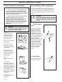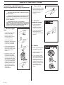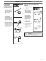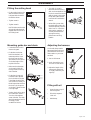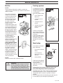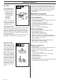
1
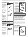
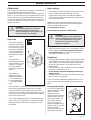
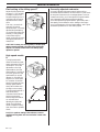
Operator's manual (EPA)
323P4 325P4X-SERIES
325P5X-SERIES
Please read these instructions carefully and make
sure you understand them before using the machine.
English
SYMBOL EXPLANATION
Symbols
WARNING! This machine can be
dangerous. Careless or incorrect use
can result in serious or fatal injury to
the operator or others.
• Always wear approved protective
gloves.
• Use anti-slip and stable boots.
Read through the Operator‘s Manual
carefully and understand the content
before using the machine.
Always use
• A protective helmet where there is
a risk of falling objects
• Ear protection
• Approved eye protection
• This product is in accordance with
applicable CE directives.
• This machine is not electrically
insulated. If the machine touches
or comes close to high-voltage
power lines it could lead to death
or serious injury. Electricity can
jump from one point to another by
arcing. The higher the voltage, the
greater the distance electricity can
jump. Electricity can also travel
through branches and other
objects, especially if they are wet.
Always keep a safe distance of at
least 10 m (30 ft) between the
machine and high-voltage power
lines and/or any objects that are
touching them. If you need to
work closer than this always
contact the relevant power
company to make sure the power is
switched off before you start work.
• This machine has a long reach.
Make sure that no people or
animals come closer than 15 m (45
ft) when the machine is running.
2 – English
Other symbols/decals on the machine refer to
special certification requirements for certain
markets.
• Checks and/or maintenance should
be carried out with the engine
switched off, with the stop switch
in the STOP position.
• Always wear approved protective
gloves.
• Regular cleaning required.
• Ocular control.
• Approved eye protection must
always be used.
• Chain oil and chain oil flow
adjustment
CONTENTS
Husqvarna AB has a policy of continuous product development
and therefore reserves the right to modify the design and
appearance of products without prior notice.
Maintenance, replacement, or repair of the emission control
devices and systems may be performed by any nonroad
engine repair establishment or individual.
!
WARNING!
Under no circumstances may the design
of the machine be modified without the
permission of the manufacturer. Always
use genuine accessories. Non-authorized
modifications and/or accessories can
result in serious personal injury or the
death of the operator or others.
Your warranty does not cover damage or
liability caused by the use of nonauthorized accessories or replacement
parts.
HUSQVARNA AB HUSKVARNA SWEDEN
IMPORTANT ENGINE INFORMATION
TWC
THIS ENGINE CONFORMS TO U.S. EP A PH1
FOR SMALL NON - ROAD ENGINES.
REFER TO OPERATOR`S MANUAL FOR
MAINTENANCE SPECIFICATIONS AND ADJUSTMENTS.
This decal certifies that the product has been approved in
accordance with American exhaust emissions requirements
EPA 1.
List of contents
SYMBOL EXPLANATION
Symbols ............................................................................... 2
CONTENTS
List of contents .................................................................... 3
SAFETY INSTRUCTIONS
Personal protective equipment ............................................. 4
The machine‘s safety equipment .......................................... 4
Control, maintenance and service of the machine‘s safety
equipment ...................................................................... 6
Specification of blade and chain ........................................... 7
Sharpening your chain and adjusting raker clearance ........... 8
Tensioning the saw chain ................................................... 10
Lubricating cutting equipment .......................................... 10
Checking wear on cutting equipment ................................ 11
General safety instructions ................................................. 12
General working instructions ............................................. 13
Safety insructions when using he machine ......................... 13
Basic working techniques ................................................... 14
WHAT IS WHAT?
What is what on the machine? ........................................... 16
ASSEMBLY
Fitting the cutting head...................................................... 17
Mounting guide bar and chain ........................................... 17
Adjusting the harness ......................................................... 17
Filling with oil ................................................................... 17
Assembling and dismantling the two-part shaft (325P5) .... 18
FUEL HANDLING
Fuel mixture ...................................................................... 19
Fuelling.............................................................................. 19
START AND STOP
Control before starting ....................................................... 20
Start and stop ..................................................................... 20
MAINTENANCE
Carburetor ......................................................................... 21
Muffler .............................................................................. 23
Cooling system .................................................................. 23
Spark plug .......................................................................... 23
Air filter ............................................................................. 24
Maintenance schedule ........................................................ 24
TECHNICAL DATA
323P4 ................................................................................ 25
325P4 ................................................................................ 25
325P5 ................................................................................ 25
EMISSION CONTROL WARRANTY STATEMENT
Your warranty rights and obligations .................................. 26
For customer assistance call: 704-921-7000 or
contact us at our website: www.husqvarna.com
English –
3
SAFETY INSTRUCTIONS
Personal protective equipment
IMPORTANT INFORMATION
• If used incorrectly or carelessly this machine
can become a dangerous tool that can cause
serious or fatal injury to the operator or others. It
is extremely important that you read and understand the content of this manual.
• When using the machine, personal protective
equipment approved by the appropriate
authorities must be used. Personal protective
equipment does not eliminate the risk of
accidents. However, it can reduce the effects of
an injury in the event of an accident. Ask your
dealer for help when choosing protective
equipment.
!
WARNING!
Remove your hearing protection as soon as
you stop the engine, so that you can hear
any noises or warning signals.
GLOVES
Gloves must be worn
whenever required, for
example when fitting,
inspecting or cleaning
cutting equipment.
PROTECTIVE HELMET
AND VISOR
EAR PROTECTION
Ear protection offering
sufficient dampening effect
should be used.
The machine‘s safety equipment
This section describes the machine‘s safety equipment, its
function and how checks and maintenance are carried out to
ensure that it operates correctly. (See the chapter “What is
what“ to locate where this equipment is positioned on your
machine.)
!
WARNING!
Never use a machine with defective safety
equipment. Follow the control, maintenance
and service instructions described in this
section.
1. Throttle trigger
lock
The throttle trigger lock is
designed to prevent the
throttle from accidentally
being engaged. When the
trigger lock (A) is pressed
into the handle (= when you
hold the handle) the throttle
(B) is released. When the
grip on the handle is
released the throttle and the
throttle trigger lock return
to their original positions.
This takes place via two
independent return spring
systems. This means that the
throttle is automatically
locked in its “idling“
position.
EYE PROTECTION
Blows from branches or
objects thrown out by the
cutting equipment can
damage the eyes.
2. Stop switch
BOOTS
Use anti-slip and stable
boots.
CLOTHING
Wear clothes made of a
strong fabric and avoid loose
clothing that can catch on
shrubs and branches. Always
wear heavy, long pants. Do
not wear jewelry, short
pants, sandals or go barefoot.
Secure hair so it is above
shoulder level.
FIRST AID KIT
The operator must carry a
first aid kit.
4 – English
The stop switch should be
used to stop the engine.
A
B
SAFETY INSTRUCTIONS
3. Vibration
damping system
Your machine is equipped
with a vibration damping
system, which is designed
to give as vibration-free
and comfortable use as
possible.
The machine’s vibration
damping system reduces
the transfer of vibrations
between the engine unit/
cutting equipment and the
machine’s handle unit.
!
WARNING!
Over exposure to vibrations can result in
blood-vessel or nerve injury to persons
suffering with blood circulation problems.
Seek medical attention if you experience
physical symptoms that can be related to
over exposure to vibrations. Examples of
such symptoms are “numbness“, lack of
feeling, “tickling“, “pricking“, “pain“ lack of
or a reduction in normal strength, changes
in the colour of the skin or its surfaces.
These symptoms normally appear in the
fingers, hands or wrists.
4. Muffler
The muffler is designed to
give the lowest possible noise
level and to direct the engine‘s
exhaust fumes away from the
operator. Muffler fitted with
catalytic converter is also
designed to reduce harmful
exhaust components.
In countries that have a warm
and dry climate the risk of fire
is obvious. We have therefore
fitted certain mufflers with a
spark arrest screen. Make sure
that your muffler is fitted
with this kind of screen.
It is extremely important that
the instructions for checking,
maintaining and servicing the
muffler are followed. (see the
section “Control, maintenance
and service of the machine‘s
safety equipment“).
!
!
WARNING!
Mufflers fitted with catalytic converters
become extremely hot during use and
after stopping. This also applies at idling
speeds. Contact can result in burns to
the skin. Be observant to the risk of fire!
WARNING!
Bear in mind that exhaust fumes:
• contain carbon monoxide, which can
cause carbon monoxide poisoning.
Therefore never start or run the machine
indoors or anywhere with inadequate
ventilation.
• are hot and can contain sparks that can
cause fires. Never start the machine
indoors or close to inflammable material.
English –
5
SAFETY INSTRUCTIONS
Inspecting, maintaining and
servicing machine safety equipment
IMPORTANT INFORMATION
• All service and repairs to the machine require
special training.
2. Stop switch
• Start the engine and make
sure that the engine stops
when the stop switch is
moved to the stop
position.
• This applies especially to the machine‘s safety
equipment. If the machine does not meet any of
the controls listed below you should contact your
service workshop.
• The purchase of one of our products
guarantees that professional repair and servicing
will be carried out on it. If the point of purchase is
not one of our servicing dealers, please ask for
details of the closest service workshop.
1. Throttle trigger
lock
• Check that the throttle is
locked in the “idling
position“ when the
throttle trigger lock is in
its original position.
3. Vibration
damping system
• Check the vibration
damping element
regularly for material
cracks and distortion.
• Check that the vibration
damping element is
undamaged and securely
attached.
• Press in the throttle
trigger lock and make sure
it returns to its original
position when released.
• Ensure that the throttle
and throttle trigger lock
move easily and that their
return spring systems
function.
• See section “Start“. Start
the machine and apply
full throttle. Release the
throttle and check that the
cutting equipment stops
and remains at a standstill.
If the cutting equipment
moves with the throttle in
the idling position, then
the carburettor’s idling
setting must be checked.
See chapter
“Maintenance“.
6 – English
4. Muffler
1. Never use a machine that
has a defective muffler.
2. Check regularly that the
muffler is secure.
3. If your muffler is fitted
with a spark arrest screen
then it should be cleaned
regularly. A blocked
screen leads to the engine
overheating with serious
damage as a result. Never
use a muffler with a
defective spark arrest
screen.
SAFETY INSTRUCTIONS
5. Cutting equipment
This section describes how through correct maintenance and
through using the right type of cutting equipment you can:
• Obtain maximum cutting capacity.
• Increase the service life of the cutting equipment.
1 Check the cutting
equipment with regard to
damage and crack
formation. Damaged
cutting equipment should
always be replaced.
2 Only use cutting
equipment recommended
by us! See the ”Technical
data” section.
3 Keep the chain cutting
teeth properly sharpened!
Follow our instructions
and use the
recommended file gauge.
A damaged or badly
sharpened chain increases
the risk of accidents.
4 Maintain the correct
raker clearance! Follow
our instructions and use
the recommended raker
gauge. Too large a
clearance increases the
risk of kickback.
5 Keep the chain properly
tesioned! If the chain is
slack it is more likely to
jump off and lead to
increased wear on the
bar, chain and drive
sprocket.
6 Keep cutting equipment
well lubricated and
properly maintained! A
poorly lubricated chain is
more likely to break and
lead to increased wear on
the bar, chain and drive
sprocket.
!
!
WARNING!
Never use a machine with defective
safety equipment. The safety equipment
should be maintained as described in this
section. If your machine does not meet
any of these controls you should contact
your service workshop.
WARNING!
Always stop the engine before carrying out
any work on the cutting equipment. This
will continue to move even after the throttle
has been released. Make sure the cutting
equipment has stopped completely and
disconnect the HT lead from the spark plug
before you start work on it.
Specification of blade and chain
When the cutting equipment supplied with your machine
becomes worn or damaged, you will need to replace it. Use
only the manufacturer approved bar and chain.
Guide bar
• Length (inches/cm)
• Number of teeth on bar
tip sprocket (T).
Small number = small tip
radius = low-kickback
• Chain pitch (inches)
The spacing between the
drive links of the chain
must match the spacing of
the teeth on the bar tip
sprocket and drive
sprocket.
• Number of drive links
The number of drive links
is determined by the
length of the bar, the chain
pitch and the number of
teeth on the bar tip
sprocket.
• Bar groove width (inches/
mm)
The groove in the bar
must match the width of
the chain drive links.
• Saw chain oil hole and
hole for chain tensioner
English –
7
SAFETY INSTRUCTIONS
Saw chain
FILE POSITION
• Saw chain pitch (inches)
Spacing between drive
links.
• Drive link width (mm/
inches).
• Number of drive links.
ROUND FILE DIAMETER
FILE DEPTH
1
5
Sharpening your chain and
adjusting raker clearance
!
WARNING!
The risk of kickback is increased with a
badly sharpened chain!
A. General information on sharpening
cutting teeth
• Never use a blunt chain. When the chain is blunt you have
to exert more pressure to force the bar through the wood
and the cuttings will be very small. If the chain is very blunt
it will not produce any cuttings at all, just wood powder.
• A sharp chain eats its way through the wood and produces
long, thick cuttings.
• The cutting part of the
A
B
chain is called the
CUTTING LINK and
this consists of a
CUTTING TOOTH
(A) and the RAKER LIP
(B). The cutting depth is
determined by the
difference in height
between the two.
• When you sharpen a
cutting tooth there are
five important
factors to remember:
FILING ANGLE
CUTTING ANGLE
8 – English
It is very difficult to sharpen
a chain correctly without the
right equipment. We recommend you to use a file gauge.
This will help you obtain the
maximum kickback
reduction and cutting
performance from your
chain.
!
The following faults will increase the
risk of kickback considerably.
• FILE ANGLE TOO
LARGE
• CUTTING ANGLE TOO
SMALL
• FILE DIAMETER TOO
SMALL
SAFETY INSTRUCTIONS
C. General advice on setting raker
clearance
B. Sharpening
cutting tooth
To sharpen cutting teeth you
will need a ROUND FILE
and a FILE GAUGE.
• When you sharpen the
cutting teeth you reduce
the RAKER
CLEARANCE (cutting
depth). To maintain
cutting performance
you must file back the
raker teeth to the
recommended height.
1. Check that the chain is
correctly tensioned. A
slack chain is difficult to
sharpen correctly.
2. Always file cutting teeth
from the inside face,
reducing the pressure on
the return stroke.
File all the teeth on one
side first, then turn the
machine over and file the
teeth on the other side.
• On a low-kickback
cutting link the front
edge of the raker lip is
rounded. It is very
important that you
maintain this radius or
bevel when you adjust
the raker clearance.
3. File all the teeth to the
same length. When the
length of the cutting teeth
is reduced to 4 mm (.16")
the chain is worn out and
should be replaced.
min 4 mm
(0,16")
• We recommend the use
of a raker gauge to
achieve the correct
clearance and bevel on
the raker lip.
!
WARNING!
The risk of kickback is increased if the
raker clearance is too large!
English –
9
SAFETY INSTRUCTIONS
D. Adjusting raker clearance
1. Undo the bar nut.
• When correction of the
raker clearance is made
the teeth must be newly
sharpened.
We recommend that you
adjust the raker clearance
every third time you
sharpen the chain.
NOTE! This
recommendation assumes
that the length of the
cutting teeth is not
reduced excessively.
2. Tension the chain by
turning the chain
tensioning screw
clockwise using the
combination spanner.
Tighten the chain until
it no longer hangs slack
beneath the bar.
• A FLAT FILE and an
RAKER CLEARANCE
GAUGE are required to
correct the raker
clearance.
• Place the gauge over the
raker lip.
• Place the file over the
part of the lip that
protrudes through the
gauge and file off the
excess. The clearance is
correct when you no
longer feel any resistance
as you draw the file over
the gauge.
Tensioning the saw chain
!
WARNING!
A slack chain may jump off and cause
serious or even fatal injury.
• The more you use a
chain the longer it
becomes. It is therefore
important to adjust the
chain regularly to take up
the slack.
• Check the chain tension
every time you refuel.
NOTE! A new chain has
a running-in period
during which you should
check and adjust the
chain tension more
frequently.
• As a rule the chain
should be tensioned as
tightly as possible, but
not so tight that you
cannot pull it round
freely by hand.
10 – English
3. Use the combination
spanner to tighten the
blade nut while lifting
the tip of the bar at the
same time. Check that
you can pull the chain
round freely by hand.
Lubricating cutting equipment
!
WARNING!
Poor lubrication of cutting equipment may
cause the chain to snap and lead to serious,
even fatal injuries.
A. Chain oil
• Chainsaw chain oil must demonstrate good adhesion to the
chain and also maintain its flow caracteristics regardless of
whether it is warm summer or cold winter weather.
• As a chainsaw manufacturer we have developed an optimal
chain oil which, with its vegetable oil base, is also
biodegradable. We recommend the use of our own oil for
both maximum chain life and to minimise environmental
damage.
• If our own chain oil is not available, standard chain oil is
recommended.
• In areas where oil specifically for lubrication of saw chains is
unavailable, ordinary EP 90 transmission oil may be used.
• Never use waste oil!
This is dangerous for yourself, the saw and the environment.
B. Filling with chain oil
The oil pump is preset at
the factory to meet most
lubrication requirements
and a full oil tank will last
about half as long as a tank
of fuel. You should
therefore check the level in
the oil tank regularly to
avoid damaging the chain
and bar by running out of
oil.
SAFETY INSTRUCTIONS
Checking wear on cutting equipment
C. Checking chain lubrication
A. Saw chain
• Check the chain
lubrication each time you
refuel.
Aim the tip of the saw at a
light coloured surface
about 20 cm away. After
1 minute running at 3/4
throttle you should see a
distinct line of oil on the
light surface.
Check the saw chain daily
for:
• Visible cracks in rivets and
links.
• Whether the chain is stiff.
• Whether rivets and links
are badly worn.
Compare the existing chain
with a new chain to decide
how badly it is worn.
When the length of the
cutting teeth has worn down
to only 4 mm the chain must
be replaced.
D. Adjusting chain lubrication
• When cutting dry or hard
species of wood it may be
necessary to increase
lubrication. To increase
the oil flow, first undo
screw (A) then turn the
adjuster screw (B)
anticlockwise. Re-tighten
screw (A). Remember that
this will increase the oil
consumption and you
should therefore check the
level in the oil tank more
frequently.
B. Chain drive wheel
A
B
Procedure if the lubrication does not
function:
• Check that the oil channel
in the bar is not
obstructed. Clean if
necessary.
Check also that the Oring is in position and is
undamaged.
• Check that the oil channel
in the gear housing is
clean. Clean if necessary.
• Check that the bar tip
sprocket turns freely. If
the chain lubrication
system is still not working
after carrying out the
above measures you
should contact your
service agent.
min 4 mm
(0,16")
Check regularly the degree of
wear on the drive wheel.
Change if it is irregularly
worn.
C.Vibration damping
system
Check regularly that the
vibration damper i free from
cracks.
Check regularly the degree of
wear on the rubber elements.
Change if worn.
D. Guide bar
Check regularly:
• Whether there are burrs
on the edges of the bar.
Remove these with a file if
necessary.
• Whether the groove in the
bar has become badly
worn. Replace the bar if
necessary.
• Whether the tip of the bar
is uneven or badly worn.
If a hollow forms on one
side of the bar tip this is
due to a slack chain.
• To prolong the life of the
bar you should turn it
over daily.
!
WARNING!
Using faulty cutting equipment may
increase the risk of accidents.
English –
11
SAFETY INSTRUCTIONS
General safety instructions
IMPORTANT INFORMATION
• The machine is only designed for tree pruning.
• The only accessories to be used with the engine
unit as a drive source are the cutting units we
recommend in the chapter “Technical data“.
• Never use the machine if you are tired, if you
have consumed alcohol, or if you are taking
medicines that can affect your sight, your judgement
or the control of your body.
• Use personal protective equipment. See the
section “Personal protective equipment“.
• Never use a machine that has been modified so
that it no longer corresponds with the original
design.
• Never use a machine that is faulty. Follow the
maintenance, control and service instructions in this
Operator‘s Manual. Some maintenance and service
actions should be carried out by trained and
qualified specialists. See the chapter “Maintenance“.
• All covers and guards must be fitted before
starting the machine. Check that the spark plug
cap and HT lead are not damaged, otherwise you
could get an electric shock.
• The machine operator shall ensure, while
working, that no persons or animals come closer
than 15 metres (50 feet). When several operators are
working in the same area the safety distance should
be at least double tree length, however, at least 15
metres (50 feet).
!
WARNING!
Faulty cutting equipment increases the risk
of accidents.
Fuel safety
• Always use a fuel container
with an anti-spill valve.
• Never fill the machine
while the engine is
running. Always stop the
engine and let it cool for a
few minutes before
refuelling.
• Provide good ventilation
when filling or mixing fuel
(petrol and 2-stroke oil).
Min. 3 m
(10 ft)
• Move the machine at least
3 m from the filling
position before starting.
• Never start the machine:
a) If you have spilt fuel on it.
Wipe up all spillage.
b)If you have spilt fuel on
yourself or your clothes.
Change your clothes.
c) If there is a fuel leak.
Make regular checks for
leakage from the fuel cap
and the fuel supply pipes.
Transport and storage
Start
!
WARNING!
When the engine is started with the choke
in either the choke or start throttle
positions, the cutting equipment starts to
move immediately.
• Store and transport the machine and fuel so that any leakage
or fumes do not risk coming into contact with sparks or
naked flames. For example, electric machines, electric
motors, electrical switches/power switches, heaters or the
like.
• The complete clutch cover with shaft must be fitted before
the machine is started, otherwise the clutch can become
loose and cause personal injury.
• When storing and transporting fuel approved containers
intended for this purpose must be used.
• Never start the machine indoors. Bear in mind the dangers
of inhaling the engine‘s exhaust fumes.
• When storing the machine for long periods the fuel tank
must be emptied. Contact your local petrol station to find
out how to dispose of excess fuel.
• Observe your surroundings and make sure that there is no
risk of people or animals coming into contact with the
cutting equipment.
• Place the machine on the
ground, ensure the cutting
equipment runs free of
twigs and stones. Push the
machine body towards the
ground using your left
hand. (NOTE! Not with your foot). Grip the starter handle
with your right hand and pull the starter cord.
12 – English
!
WARNING!
Exercise great care when handling fuel and
chain oil. Bear in mind the risk of fire,
explosions and inhaling fumes.
• If the machine is to be transported on a vehicle, it must be
secured to avoid damage or fuel leakage. You should also
make sure that the machine cannot injure any person or
animal during transport. Observe relevant traffic regulations.
• The transport guard must be fitted during transport and
storage.
SAFETY INSTRUCTIONS
Safety instructions when using the
machine
!
WARNING!
The machine can cause serious injury.
Read the safety instructions carefully.
Learn how to use the machine.
Protective instructions while working
• Always ensure you have a
safe and firm working
position.
• Always use both hands to
hold the machine. Hold
the machine on the side
of the body.
• Use your right hand to
operate the throttle.
!
WARNING!
Cutting tool. Do not touch the tool
without first switching off the engine.
NOTE! Read the Operator’s Manual carefully before using
the machine.
Personal protection
• Always wear boots, and the
other safety equipment
described in the section
”Personal protective
equipment”.
• Always wear working
clothes and thick, long
trousers.
• Never wear loose fitting
clothes or jewellery
• Secure hair so it is above
shoulder level.
Protective instructions regarding the
surroundings
• Never allow children to
use the machine.
• Ensure no one comes
within 15 metres while
working.
• Make sure that your
hands and feet cannot
come into contact with
the cuttingequipment
when the engine is
running.
• When the engine is
switched off, keep your
hands and feet away from
the cuttingequipment
until it has stopped.
• Watch out for stumps of
branches that can be
thrown out during
cutting.
• Always lay the machine
on the ground when you
are not using it.
• Check the working area for foreign objects such as electricity
cables, insects and animals, etc, and for other objects that
could damage the cutting attachment, such as metal items.
• If any object is hit or if vibrations occur stop the machine
immediately. Remove the spark plug cable from the spark
plug. Check that the machine is not damaged. Repair any
damage.
• If anything gets caught up in the cutting equipment while
you are working, switch off the engine and wait for it to stop
completely before cleaning the cutting equipment. Remove
the spark plug cable from the spark plug.
• Never allow anyone to use
the machine without first
being absolutely sure that
they understand the
contents of the Operator’s
Manual.
• Never work on a ladder,
stool or any other raised
position that is not fully
secured.
English –
13
SAFETY INSTRUCTIONS
Protective instructions when
work is completed
• The transport guard should always be fitted to the
cuttingequipment when the machine is not in use.
• Ensure the cuttingequipment has stopped and remove the
spark plug cable from the spark plug before carrying out
cleaning, repairs or an inspection.
• Always wear heavy duty
gloves when repairing the
chain. The cuttingequipment is extremely
sharp and can easily
causes cuts.
Observe great care when working close to overhead power
lines. Falling branches can result in short-circuiting.
!
!
• Store the machine out of
reach from children.
• Only use original spare
parts when carrying out
repairs.
WARNING!
Observe the applicable safety regulations
for work in the vicinity of overhead power
lines.
WARNING!
This machine is not electrically insulated.
If the machine touches or comes close to
live electricity lines, it could cause death
or serious injury. Electricity can jump from
one point to another in the form of a highvoltage arc. The higher the voltage, the
further the electricity can jump. Electricity
can also be conducted by branches and
other objects, especially if they are wet.
Always keep a distance of at least 10 m (30
ft) between the machine and live electricity
lines and/or objects that are touching
them. If you have to work closer than this,
always contact the relevant power company to make sure the power is switched
off before you start your work.
Basic working techniques
• The machine should be
held as close to the body
as possible to get the best
balance.
• Make sure that the tip
does not touch the
ground.
• Do not rush the work,
but work steadily until all
the branches have been
cut back cleanly.
• Always drop to idling
speed after each working
operation. Longer periods
running at full throttle
without loading the
engine can lead to serious
engine damage.
• Allways cut with the engine
at full throttle.
• Let the engine drop back to
idle between each cut. Long
periods at full throttle can
cause serious damage to
the centrifugal clutch.
!
14 – English
Never stand directly underneath a branch
that is being cut, otherwise you may suffer
serious or even fatal injury.
!
WARNING!
This machine has a long reach. Make sure
that no people or animals come closer than
15 m (45 ft) when the machine is running.
• Whenever possible position
yourself so that you can
make the cut at right angles
to the branch.
• Do not work with the shaft
held straight out in front of
you (like a fishing rod).
This increases the apparent
weight of the cutting
equipment.
• Cut large branches in stages
to give better control over
where they fall.
• Never cut through the
swelling at the root of the
branch as this will slow
down healing and increase
the risk of fungal attack.
90
SAFETY INSTRUCTIONS
• Use the stop at the base of
the bar to provide support
during cutting. This will
help prevent the cutting
equipment from jumping
on the branch.
• Make an initial cut on the
underside of the branch
before cutting through the
branch from above. This
will prevent tearing of the
bark, which could lead to
slow healing and cause
permanent damage to the
tree. The first cut should
not be deeper than 1/3 of
the branch thickness to
prevent jamming. Keep the
chain running while you
withdraw the cutting
equipment from the branch
to prevent it jamming.
• Use the harness to support
the weight of the machine
and make it easier to
handle.
• Make sure you have a firm
footing and will not be
hampered by branches,
stones and other trees.
!
WARNING!
Never use the throttle without having a
full view of the cutting equipment.
English –
15
WHAT IS WHAT?
22
24
31
23
1
2
21
19
18
6
8
5
10
9
11
17
16
4
7
12
14
15
25
20
13
3
29
26
23
28
27
What is what on the machine?
1.
2.
3.
4.
5.
6.
7.
8.
9.
10.
11.
12.
13.
14.
15.
Lubricant filler hole
Bevel gearbox
Chain lubrication adjustment screw (B)
Chain lubrication locking screw (A)
Shaft
Front handle
Throttle control
Stop switch
Throttle lock
Hook for harness
Cylinder cover
Starter handle
Fuel tank
Choke control
Fuel pump
16 – English
16. Air filter cover
17. Clutch cover
18. Chain guard
19. Bar nut
20. Chain tensioning screw
21. Chain
22. Bar
23. Chain oil tank
24. Chain oil filler hole
25. Operator’s manual
26. Transport guard
27. Allen key
28. Combination spanner
29. Harness
31. Shaft coupling (325P5)
ASSEMBLY
Fitting the cutting head
• The chain is correctly
tensioned when there is no
slack on the underside of the
bar, but it can still be turned
easily by hand. Hold up the
bar tip and tighten the bar
nuts with the combination
wrench.
• Fit the cutting head on the
shaft so that the screw (A)
is aligned with the hole in
the shaft as shown.
• Tighten screw A.
B
• When fitting a new chain,
the chain tension has to be
checked frequently until the
chain is run-in. Check the
chain tension regularly. A
correctly tensioned chain
gives good cutting
performance and long
lifetime.
• Tighten screw B.
NOTE! Make sure that the
drive shaft inside the shaft
engages with the cut-out in
the cutting head.
A
Mounting guide bar and chain
Adjusting the harness
• Unscrew the bar nut and
remove the guard.
You should always use the
harness with the machine to
give maximum control and
reduce strain on your arms
and back.
• Fit the bar over the bar
bolt.Place the bar in its
rearmost position. Place
the chain over the drive
sprocket and in the groove
on the bar. Begin on the
top side of the bar.
1. Put on the harness.
2. Hook the machine onto
the hook on the harness.
A
• Make sure that the edges
on the cutting links are
facing forward on the top
side of the bar.
• Fit the clutch cover and
locate the chain adjuster
pin in the hole on the bar.
Check that the drive links
of the chain fit correctly on
the drive sprocket and that
the chain is in the groove
on the bar. Tighten the bar
nut finger tight.
• Tension the chain by using
the combination wrench.
Turn the chain adjuster
screw clockwise. The chain
should be tensioned until it
fits snugly on the
underside of the bar.
3. Adjust the length of the
harness so that the hook
is roughly level with your
right hip.
B
Filling with oil
•
Open the cap on top of
the cutting head.
•
Fill with Husqvarna
Chain Oil.
•
Refit the cap.
English –
17
ASSEMBLY
Assembling and dismantling the
two-part shaft (325P5)
Assembling:
• Make sure the handle is
loose.
• Guide the cut-out on the
lower section of the shaft
into the coupling‘s
locking plate on the
upper section of the
shaft. The sections are
then locked together.
• Tighten the handle.
Dismantling
• Undo the handle (at least
three turns).
• Press the handle towards
the coupling.
• Carefully twist the lower
section out of the lock.
• Hold both parts of the
shaft and pull out the
lower section from the
coupling.
18 – English
FUEL HANDLING
Fuel mixture
NOTE!
The machine is fitted with a two-stroke engine and must
always be run on a mixture of gasoline and two-stroke oil. It is
important to measure the quantity of oil accurately, to ensure
the correct mixture ratio. Small discrepancies in the amount of
oil have a great bearing on the proportions of the fuel mixture
when mixing small amounts of fuel.
!
WARNING!
Always provide good ventilation when
handling fuel.
Gasoline
NOTE!
Always use high grade
unleaded oil mixed gasoline
(minimum 87 RON).
Leaded fuel will destroy the
catalytic converter and it
will no longer serve its
purpose.
• This engine is certified to
operate on unleaded
gasoline.
• The lowest recommended
octane rating is 87. If you
run the engine on lower
octane rating than 87 socalled “knocking“ can
occur. This leads to an
increased engine
temperature, which can
result in a serious engine
breakdown.
• When working at
continuous high revs a
higher octane rating is
recommended.
Two-stroke oil
• For the best results use
HUSQVARNA two-stroke
oil, which has been
specially developed for
clearing saws and chain
saws.
Mixing ratio 1:50 (2%).
Mixture
• Always mix gasoline and oil in a clean container intended for
fuel.
• Always start by filling half the quantity of gasoline required.
Then add the entire oil quantity. Mix (shake) the fuel
mixture. Fill the remaining quantity of gasoline.
• Mix (shake) the fuel mixture carefully before filling in the
machine‘s fuel tank.
• Do not mix more than max. one month’s supply of fuel.
• If the machine is not used for a long period of time, the fuel
tank should be emptied and cleaned.
• This engine is certified to operate on unleaded gasoline.
!
WARNING!
The catalytic converter muffler gets very hot
during and after use. This also applies
during idling. Be aware of the fire hazard,
especially when handling the machine near
flammable substances or vapours.
Fuelling
!
WARNING!
The following precautions reduce the risk of
fire:
Do not smoke or place any sources of heat
in the vicinity of the fuel. Never refuel when
the engine is running. Always stop the
engine and let it cool for a few minutes
before refuelling. Open the fuel cap slowly
when fuelling so that any over pressure is
released slowly. Tighten the fuel cap
carefully after refuelling. Always move the
machine from the fuelling place before
starting.
• Clean around the fuel cap.
Contamination in the tank
can disrupt operations.
• Ensure that the fuel is well
mixed by shaking the
container before filling the
tank.
Min. 3 m
(10 ft)
Gasoline
Oil
2%(1:50)
Lit.
Lit.
• Never use two-stroke oil
intended for water cooled
outboard motors, so-called
outboard motor oil.
5
10
15
20
0,10
0,20
0,30
0,40
US
gallon
US
fl. oz.
• Never use oil intended of
four-stroke engines.
1
2 1/2
5
2 1/2
6 1/2
12 7/8
English –
19
START AND STOP
Control before starting
• Inspect the working area. Remove objects that can be
thrown.
• Check the cuttingequipment. Never use
blunt, cracked or
damaged equipment.
• Check that the machine
is in full working order.
Check that all nuts and
bolts are tightened
correctly.
• Make sure the chain is always well lubricated.
• Ensure the cuttingequipment always stop when the engine
is idling.
• Only use the machine for what it is intended for.
• Ensure that the handle and safety functions are in order.
Never use a machine that lacks a part or has been modified
outside of the specifications.
Start and stop
!
WARNING!
The complete clutch cover with shaft must
be fitted before the machine is started,
otherwise the clutch can become loose
and cause personal injury.
Always move the machine from the filling
area before starting. Place the machine on
a flat surface. Ensure the cutting
equipment cannot come into contact with
any object. Make sure no unauthorised
persons are in the working area,
otherwise there is a risk of serious
personal injury. The safety distance is 15
metres.
Cold engine
IGNITION:
Set the stop switch to the
start position.
CHOKE:
Set the choke control in the
choke position.
AIR PURGE:
Press the air purge
diaphragm repeatedly until
fuel begins to fill the
diaphragm. The diaphragm
need not be completely
filled.
Warm engine
Use the same starting
procedure as for the cold
engine, but do not set the
choke control in the choke
position. The start throttle position is obtained by setting the
choke control in the choke position and then returning it to its
original position.
20 – English
Stop
The engine is stopped by
switching off the ignition.
!
WARNING!
When the engine is started with the choke
in the choke or start position the cutting
equipment starts to rotate immediately.
Start
Press the machine body
against the ground using
your left hand (NOTE! Not
your foot). Grip the starter
handle, slowly pull out the
cord with your right hand
until you feel some resistance
(the starter pawls grip), now
quickly and powerfully pull
the cord.
Reset the choke control as
soon as the engine fires and
repeat until the engine starts.
When the engine starts
quickly apply full throttle
and the start throttle will
automatically disengage.
NOTE! Do not pull the
starter cord out completely
and do not release the starter
cord from the fully extended
position. This can damage
the machine. Also take care
to ensure that the cutting
attachment is not touching
the ground when you start
the machine.
MAINTENANCE
Carburetor
Your Husqvarna product has been designed and manufactured
to specifications that reduce harmful emissions.
After your unit has been run 8-10 tanks of fuel the engine has
broken in. To ensure that your unit is at peak performance and
producing the least amount of harmful emissions after break
in, have your authorized servicing dealer, who has a revolution
counter at his disposal, to adjust your carburetor for optimum
operating conditions.
!
WARNING!
The complete clutch cover with shaft
must be fitted before the machine is
started, otherwise the clutch can become
loose and cause personal injury.
Operation
• The carburetor governs
the engine‘s speed via the
throttle. Air/fuel is mixed
in the carburetor. The air/
fuel mixture is adjustable.
To take advantage of the
engine‘s optimal output
the adjustment must be
correct.
• The setting of the
carburetor means that the
engine is adapted to local
conditions, for example,
the climate, altitude,
gasoline and the type of 2stroke oil.
• The carburetor is
equipped with three
adjustment possibilities:
L = Low speed needle
H= High speed needle
T = Idle speed adjuster
screw
• The fuel quantity in relation to the air flow permitted by the
throttle opening is adjusted using the L and H-needles.
Turning the needles clockwise gives a leaner fuel mixture
(less fuel) and turning them anti-clockwise gives a richer fuel
mixture (more fuel). A leaner mixture gives high revs while a
richer mixture give less revs.
• The T-screw regulates the position of the throttle while the
engine is idling. Turning the screw clockwise gives a higher
idling speed while turning it anti-clockwise gives a lower
idling speed.
Basic setting
• The carburetor is set to its basic setting when test run at the
factory. The basic setting should be kept during the
machine‘s first working hours. Thereafter the carburetor
should be finely adjusted. Fine adjustment should be carried
out by a skilled technician.
NOTE! If the cutting attachment rotates/moves while the
engine is idling the T-screw should be turned anti-clockwise
until the cutting attachment stops.
Rec. idling speed: 2 700 rpm.
Recommended max. speed: See “Technical Data” .
!
WARNING!
If the idling speed cannot be adjusted so
that the cuttingequipment stops, contact
your service workshop. Do not use the
machine until it has been correctly
adjusted or repaired.
Fine adjustment
• When the machine has been ”run-in” the carburetor should
be finely adjusted. The fine adjustment should be carried
out by qualified person. First adjust the L-jet, then the
idling screw T and then the H-jet.
Conditions
• Before any adjustments are made the airfilter should be clean
and the airfilter cover fitted. Adjusting the carburetor while
a dirty airfilter is in use will result in a leaner mixture when
the filter is finally cleaned. This can give rise to serious
engine damage.
• Carefully turn the L and H needle to the mid point between
fully turned in and fully turned out..
• Do not attempt to adjust the needles beyond the stops as
damage can occur.
• Now start the machine according to the starting instructions
and run it warm for 10 minutes.
NOTE! If the cutting attachment rotates/moves the T screw
should be turned anti-clockwise until the cutting attachment
stops.
Low speed needle L
Try to find the highest idling
speed, turning the low speed
needle L clockwise
respectively counterclockwise. When the highest
speed has been found, turn
the low speed needle L 1/4
turn counter-clockwise.
NOTE! If the cuttingequipment rotates/moves in
the idling position, turn the
idling speed screw T
counter-clockwise until the
cutting attachment stops.
+ 1/4
L
English –
21
MAINTENANCE
Final setting of the idling speed T
Correctly adjusted carburetor
Adjust the idling speed with
the screw T, if it is necessary
to readjust. First turn the
idle speed adjusting screw T
clockwise until the cuttingeqipment starts to rotate/
move.
Then turn, counter-clockwise until the cuttingequipment stops. A correctly
adjusted idle speed setting
occurs when the engine runs
smoothly in every position.
It should also be good
margin to the rpm when the
cuttingequipment starts to
rotate/move.
A correctly adjusted carburetor means that the machine
accelerates without hesitation and the machine 4-cycles a little
at max speed. Furthermore, the cuttingequipment, must not
rotate/move at idling. A too lean adjusted low speed needle L
may cause starting difficulties and bad acceleration.
A too lean adjusted high speed needle H gives lower power =
less capacity, bad acceleration and/or damage to the engine.
A too rich adjustment of the two speed needles L and H gives
acceleration problems or too low working speed.
CAUTION! Contact your servicing dealer, if the idle speed
setting cannot be adjusted so that the cutting attachment
stops. Do not use the machine until it has been properly
adjusted or repaired.
High speed needle
H
The high speed needle
affects the machine’s power,
speed, temperature and fuel
consumption. A too lean
adjustment on the high
speed needle H (the high
speed needle H is screwed in
too much) gives a too high
speed resulting in engine
damage. Do not allow the
engine to run at full speed
for more than 10 seconds.
Apply full throttle and turn
the high speed needle H
slowly anticlockwise until
the engine runs unevenly.
The high speed needle H is
then turned slowly
clockwise a little until the
engine runs smoothly.
Note the engine should be
run unloaded when
adjusting the high speed
needle. The high speed
needle is adjusted correctly
when the machine ‘splatters’
a little .
H
NOTE! For optimum setting of the carburetor, contact a
qualified servicing dealer who has a revolution counter at his
disposal.
22 – English
MAINTENANCE
Muffler
Cooling system
NOTE!
Some mufflers are fitted with a catalytic converter. See
“Technical data” to see whether your machine is fitted with a
catalytic converter.
To maintain as low operating temperature as possible
the engine is equipped with
a cooling system.
The cooling system consists
of:
1. An air intake on the
starter unit.
The muffler is designed to
dampen the noise level and
to direct the exhaust fumes
away from the user. The
exhaust fumes are hot and
can contain sparks, which
can result in fire if the
exhaust fumes are directed
towards a dry and
inflammable material. Some
mufflers are equipped with a
special spark arrest screen. If
your machine is fitted with
this type of screen it should
be cleaned regularly. This is
done using a wire brush. On
mufflers without a catalytic
converter the screen should
be cleaned weekly, or
replaced if necessary. On
mufflers fitted with a
catalytic converter the screen
should be checked and
cleaned monthly. If the
screen is damaged it should
be replaced. If the screen is
frequently blocked, this can
be a sign that the function of
the catalytic converter is
impaired. Contact your
dealer to inspect the muffler.
A blocked screen will cause
the engine to overheat
resulting in damage to the
cylinder and piston. Also see
under “Maintenance”.
NOTE!
Never use a machine with a defective muffler.
!
WARNING!
Mufflers fitted with catalytic converters
become extremely hot during use and
after stopping. This also applies at idling
speeds. Contact can result in burns to
the skin. Be observant to the risk of fire!
4
2. Cooling fins on the
flywheel.
3
2
3. Cooling fins on the
cylinder
4. Cylinder cover (leads
cold air onto the
cylinder).
1
Clean the cooling system
using a brush at least once a
week, in difficult conditions
more often.
A dirty or blocked cooling
system leads to the engine
overheating resulting in
damage to the cylinder and
piston.
Spark plug
The condition of the spark
plug is affected by:
•
An incorrect carburetor
setting.
•
An incorrect fuel
mixture (too much or
faulty oil).
•
A dirty air filter.
0,5 mm
These factors cause deposits
on the spark plug electrode
that may result in
malfunction or starting
difficulties.
If the machine is low on power, difficult to start or runs
poorly while idling always check the spark plug first.
If the spark plug is dirty, clean it and at the same time check
that the electrode gap is 0.5 mm. The spark plug should be
changed after about one month of operation or earlier if
necessary.
NOTE! Always use the recommended type of spark plug. An
incorrect spark plug can damage the cylinder/piston.
English –
23
MAINTENANCE
Air filter
The air filter should be
cleaned regularly removing
dust and dirt to avoid:
• carburetor malfunction
• starting problems
• reduced engine power
• unnecessary wear to
engine parts
• abnormal fuel
consumption
Clean the filter after every
25 hours or more regularly
if operating conditions are
exceptionally dusty.
Cleaning the air filter
Dismantle the air filter cover and remove the air filter. Wash in
clean, warm soapy water. Ensure that the filter is dry before
refitting. An air filter used for a long period of time can never
be cleaned completely. Therefore it is necessary to replace the
filter from time to time with a new filter. A damaged air filter
must always be replaced.
If the machine is used in dusty conditions the air filter should
be soaked in oil, see the section on “Oiling the air filter“.
Oiling the air filter
Always use HUSQVARNA
filter oil, order no. 503 47
73-01. The filter oil contains
a solvent to make it spread
evenly through the filter. You
should therefore avoid skin
contact. Put the filter in a
plastic bag and the pour the
filter oil over it. Knead the
plastic bag to distribute the
oil. Squeeze the excess oil out
of the filter inside the plastic
bag and pour off the excess
before fitting the filter on the
machine. Never use common
engine oil. This would drain
through the filter quite
quickly and collect in the
bottom.
24 – English
NOTE: Use only HUSQVARNA replacement parts. Use of
other brands of replacement parts can cause damage to your
unit or injury to the operator or others. Your warranty does
not cover damage or liability caused by the use of accessories
and/or attachments not specifically recommended by
HUSQVARNA.
Maintenance schedule
Below you will find some general maintenance instructions.
Daily maintenance
•
•
•
•
•
•
•
•
Clean the exterior of the machine.
Check throttle trigger and throttle trigger lockout function.
Check stop switch function.
Check that chain does not rotate at idling.
Check that the harness is undamaged.
Check that nuts and screws are sufficiently tightened.
Check for fuel leaks.
Clean the area under the protective cover.
Weekly maintenance
•
•
•
•
•
•
Check the starter, especially cord and return spring.
Clean the carburetor area.
Clean the exterior of the spark plug.
Remove it and check the electrode gap.
Adjust it to 0,5 mm (.020"), or change the spark plug.
Clean the cooling fins on the cylinder and check that the air
intake at the starter is not clogged.
• Clean the air filter.
• Clean or replace the muffler’s spark arrest screen (only
mufflers without a catalytic converter).
• File off any burrs on the sides of the bar.
Monthly maintenance
•
•
•
•
•
•
•
•
•
•
Clean the fuel tank.
Clean the exterior of the carburetor and the space around it.
Clean the fan and the space around it.
Check fuel hose for cracks or other damage. Change if
necessary.
Change fuel filter in fuel tank.
Check clutch, clutch spring and clutch drum for wear.
Change if necessary.
Check electrical wires and connections.
Change the spark plug.
Change the airfilter.
Check and clean the muffler’s spark arrest screen if necessary
(only mufflers with a catalytic converter).
TECHNICAL DATA
Technical data
323P4
325P4
325P5
Engine
Displacement, cu. in/cm3
Cylinder bore, inch/mm
Stroke length, inch/mm
Recommended max. speed, rpm
Idling speed, rpm
Max. engine output, acc. to ISO 8893
Catalytic converter muffler
Speed-regulated ignition system
1,50/24,5
1,34/34
1,06/27
12 500
2 700
0,9 kW/ 9 000 rpm
Yes
Yes
1,50/24,5
1,34/34
1,06/27
12 500
2 700
0,9 kW/ 9 000 rpm
Yes
Yes
1,50/24,5
1,34/34
1,06/27
12 500
2 700
0,9 kW/9 000 rpm
Yes
Yes
Ignition system
Manufacturer/type of ignition system
Spark plug
Electrode gap, inch/mm
Walbro MB
NGK BPMR 7A
0,02/0,5
Walbro MB
NGK BPMR 7A
0,02/0,5
Walbro MB
NGK BPMR 7A
0,5
Fuel lubrication system
Manufacturer/type of carburetor
Fuel tank capacity, US pint/litres
Zama C1Q
1,06/0,5
Zama C1Q
1,06/0,5
Zama C1Q
1,06/0,5
Chain lubrication system
Oil tank capacity, US pint/litres
0,36/0,17
0,36/0,17
0,36/0,17
Weight
Weight without fuel, cutting tool and
guard, Lbs/kg
11,0/5,0
11,2/5,1
13,0/5,9
94
92
92
107
105
105
1,3/1,9
4,0/3,1
2,2/2,6
6,6/7,5
1,2/1,6
8,6/7,6
Sound levels
(see note 1)
Equivalent noise pressure level at the user’s ear,
measured according to EN/ISO 11680-1, dB(A):
Equivalent noise power level at the user’s ear,
measured according to EN/ISO 11680-1 and
ISO 10884, dB(A):
Vibration levels
Vibration levels on the handles, measured
according to EN/ISO 11680-1 m/s2
When idling, left/right handles:
At max. speed, left/right handles:
Note 1: Equivalent pressure level is calculated as the time-weighted energy total for sound levels under various working conditions
with the following time distribution: 1/2 idling and 1/2 max speed.
English –
25
TECHNICAL DATA
Bar and chain combinations
The following combinations are CE approved.
Bar
Chain
Length,
inches
Pitch,
inches
Max. no of teeth
on tip sprocket
10
3/8
7T
Husqvarna S 36/Oregon 91 VG
12
3/8
7T
Husqvarna S 36/Oregon 91 VG
10
3/8
7T
Oregon 90 SG
12
3/8
7T
Oregon 90 SG
L
1
5
Type
Inch
Inch/mm
Inch/mm
Angle
Angle
Angle
Inch/mm
Inch/cm: dl
91VG
3/8"
0,050"/1,3
5/32" /4,0
85°
30°
0°
0,025"/0,65
10"/25:40
12"/30:45
S 36
3/8"
0,050"/1,3
5/32" /4,0
85°
30°
0°
0,025"/0,65
10"/25:40
12"/30:45
90SG
3/8"
0,028"/1,1
5/32"/4,0
85°
30°
0°
0,025"/0,65
10"/25:40
12"/30:45
26 – English
´+H(Q¶5,¨
EMISSION CONTROL WARRANTY STATEMENT
YOUR WARRANTY RIGHTS AND
OBLIGATIONS
The EPA (The US Environmental Protection Agency),
Environment Canada and Husqvarna Forest & Garden are
pleased to explain the emissions control system warranty
on your 2001 and later small nonroad engine. In U.S. and
Canada, new small nonroad engines must be designed,
built and equipped to meet the federal stringent anti-smog
standards. Husqvarna Forest & Garden must warrant the
emission control system on your small nonroad engine for
the periods of time listed below provided there has been no
abuse, neglect or improper maintenance of your unit. Your
emission control system includes Parts such as the
carburetor and the ignition system.
Where a warrantable condition exists, Husqvarna Forest &
Garden will repair your small nonroad engine at no cost to
you. Expenses covered under warranty include diagnosis,
parts and labor.
MANUFACTURER’S WARRANTY
COVERAGE
The 2001 and later small nonroad engines are warranted
for two years. If any emission related part on your engine
(as listed above) is defective, the part will be repaired or
replaced by Husqvarna Forest & Garden.
OWNER’S WARRANTY
RESPONSIBILITIES
As the small nonroad engine owner, you are responsible
for the performance of the required maintenance listed in
your Operator’s Manual. Husqvarna Forest & Garden
recommends that you retain all receipts covering
maintenance on your small nonroad engine, but
Husqvarna Forest & Garden cannot deny warranty solely
for the lack of receipts or for your failure to ensure the
performance of all scheduled maintenance.
As the small nonroad engine owner, you should, however,
be aware that Husqvarna Forest & Garden may deny you
warranty coverage if your small nonroad engine or a part of
it has failed due to abuse, neglect, improper maintenance,
unapproved modifications or the use of parts not made or
approved by the original equipment manufacturer.
You are responsible for presenting your small nonroad
engine to a Husqvarna Forest & Garden authorized
servicing dealer as soon as a problem exists. The warranty
repairs should be completed in a reasonable amount of
time, not to exceed 30 days.
If you have any questions regarding your warranty rights
and responsibilities, you should contact your nearest
authorized servicing dealer or call Husqvarna Forest &
Garden at 1-800-487-5963.
WARRANTY COMMENCEMENT DATE
The warranty period begins on the date small nonroad
engine is delivered.
LENGTH OF COVERAGE
Husqvarna Forest & Garden warrants to the initial owner
and each subsequent purchaser that the engine is free
from defects in materials and workmanship which cause
the failure of a warranted part for a period of two years.
WHAT IS COVERED
REPAIR OR REPLACEMENT OF PARTS
Repair or replacement of any warranted part will be
performed at no charge to the owner at an approved
Husqvarna Forest & Garden servicing dealer. If you have
any questions regarding your warranty rights and
responsibilities, you should contact your nearest
authorized servicing dealer or call Husqvarna Forest &
Garden at 1-800-487-5963.
WARRANTY PERIOD
Any warranted part which is not scheduled for replacement
as required maintenance, or which is scheduled only for
regular inspection to the effect of ”repair or replace as
necessary” shall be warranted for 2 years. Any warranted
part which is scheduled for replacement as required
maintenance shall be warranted for the period of time up to
the first scheduled replacement point for that part.
DIAGNOSIS
The owner shall not be charged for diagnostic labor which
leads to the determination that a warranted part is
defective, if the diagnostic work is performed at an
approved Husqvarna Forest & Garden servicing dealer.
CONSEQUENTIAL DAMAGES
Husqvarna Forest & Garden may be liable for damages to
other engine components caused by the failure of a
warranted part still under warranty.
WHAT IS NOT COVERED
All failures caused by abuse, neglect or improper
maintenance are not covered.
ADD -ON OR MODIFIED PARTS
The use of add-on or modified parts can be grounds for
disallowing a warranty claim. Husqvarna Forest & Garden
is not liable to cover failures of warranted parts caused by
the use of add-on or modified parts.
HOW TO FILE A CLAIM
If you have any questions regarding your warranty rights
and responsibilities, you should contact your nearest
authorized servicing dealer or call Husqvarna Forest &
Garden at 1-800-487-5963.
WHERE TO GET WARRANTY SERVICE
Warranty services or repairs shall be provided at all
Husqvarna Forest & Garden authorized servicing dealers.
MAINTENANCE, REPLACEMENT AND
REPAIR OF EMISSION-RELATED PARTS
Any Husqvarna Forest & Garden approved replacement
part used in the performance of any warranty maintenance
or repairs on emission-related parts, will be provided
without charge to the owner if the part is under warranty.
EMISSION CONTROL WARRANTY
PARTS LIST
1. Carburetor and internal parts
2. Intake pipe, airfilter holder and carburetor bolts.
3. Airfilter and fuelfilter covered up to maintainance
schedule.
4. Ignition System
a) Spark Plug, covered up to maintenance schedule
b) Ignition Module
5. Muffler with catalytic converter
MAINTENANCE STATEMENT
The owner is responsible for the performance of all required
maintenance, as defined in the operator’s manual.
English –
27
114 00 84-95
´+H(Q¶5,¨
2002W22