1
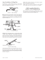
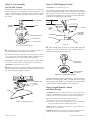
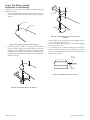
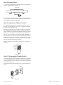
® SINCE 1 886 INSTALLATION INSTRUCTIONS FOR HUNTER CEILING FANS READ AND SAVE THESE INSTRUCTIONS CAUTION: 1. Read entire instructions carefully before beginning installation. 2. To avoid possible electrical shock, be certain electricity is shut off at main panel before wiring. 3. All wiring must be in accordance with national and local electrical codes. If you are unfamiliar with wiring, you should use a qualified electrician. Step 3: Installation of Outlet Box and Rough-In Wiring CAUTION: Your Hunter ceiling fan with accessories can weigh up to 35 lbs. The following precautions must be taken for safety and to ensure that your fan is securely mounted to the ceiling. • Be certain electricity is “off” at fuse panel when inspecting or repairing installation site. • All wiring must meet local and national electrical codes. • Do not mount directly to an unsupported ceiling or to an electrical outlet box. Mounting must support a 35 lb. fan with accessories. WARNING: 1. To reduce the risk of fire or electrical shock, do not use a solid state speed control with this fan. Use Hunter Controls only. 2. To reduce the risk of personal injury, do not bend the blade brackets when installing the brackets or cleaning the fan. Do not insert foreign objects in between rotating fan blades. 3. To reduce the risk of personal injury, install the fan only to the building structure according to these instructions, and use only the hardware supplied. A. Secure metallic outlet box 4” x 1-1/2” or 4” x 1/2” deep to 2 x 4 cross brace between two ceiling joists as shown in Figure 2. The outlet box must be recessed into the ceiling by 1/16” minimum. Secure the outlet box to the cross brace by drilling (2) pilot holes no larger than the minor diameter of the wood screws (5/64”) and use two #8 x 1-1/2” wood screws and washers. Use the innermost holes for securing the box. Orient the box so the outermost holes will be used in Step 4B. Step 1: Pre-Installation Instructions A. Select installation site. Check to see that in normal use no object can come in contact with the rotating fan blades. The mounting site should also meet the precautions listed in Step 3 below. CAUTION: Do not use a lubricant on screws. 2 X 4 BRACE B. Installation hardware is included for a standard drywall or plaster ceiling. You will need a 4” x 1-1/2” or a 4” x 1/2” outlet box and wire nuts (2) which can be purchased from any hardware store or electrical supply house. CEILING JOIST C. The fan blades must be mounted at least 7’ above the floor. For maximum efficiency, they should not have any obstruction (walls, posts, etc.) within 24” of the blade tips. See Figure 1 for mounting distances. CEILING OUTLET BOX #8 WOOD SCREW & WASHER (2) REQUIRED FIGURE 2. Step 2: Inspection of Fan A. Unpack the fan carefully to avoid any damage to the components. B. Check for any shipping damage to the motor and the fan Outlet Box B. Bring electrical cable into the outlet box and attach with an approved connector. Make certain that wiring meets all national and local electrical codes. Wire leads should extend at least 6” beyond outlet box for ease in making connections. See Figure 3. blades. If more than one fan is being installed, keep the matched and balanced fan blades in sets, as they were shipped. Should one of the fan blades become damaged during shipment, return all blades in the set for replacement. C. Check contents to be certain it contains a bag of parts. 8’ MIN. CEILING TO FLOOR 7’ MIN. TO FLOOR 24” CLEARANCE TO OBSTRUCTIONS CONNECTOR FIGURE 3. Wiring Outlet Box Figure 1. Wall Clearances 41675-01 01/07/2004 6” MIN. LEAD LENGTH 1 © 2004 Hunter Fan Company™ Step 4: Installation of Ceiling Plate A. Install the (3) rubber bushings into the top of the ceiling NOTE: When attaching ceiling plate to the outlet box support, make certain bushings remain in place. NOTE: Tighten the ceiling plate mounting screws only enough to provide slight compression of the bushings. Do not overtighten. plate by inserting small side of the rubber bushing into the three holes in the ceiling plate. See Figure 4. RUBBER BUSHING NOTE: Assembly Methods For Installer’s Choice Hanging System Your new Hunter fan can be hung in (2) different manners. (1) as a low profile fan or (2) as a ball type hanging fan. Please read Steps 5 through 7 and decide which style mounting to use. CEILING PLATE FIGURE 4. Rubber Bushings B. Thread the lead wires through the opening in the ceiling plate and install the ceiling plate to the 2 x 4 brace which supports the outlet box. Use (2) #10 wood screws 3” long and (2) flat washers for mounting. Drill (2) pilot holes for the mounting screws 9/64” diameter. See Figure 4A. RUBBER BUSHING CEILING PLATE FLAT WASHER 3” WOOD SCREW FIGURE 4A. Installing Ceiling Plate NOTE: When mounting the fan on a vaulted ceiling, make sure that one set of elongated slots in the ceiling plate is aligned vertically with the ceiling joist, or horizontally with the cross brace if a cross brace is used. Be sure one of the threaded screw holes in the side of the ceiling plate is facing down. See Figure 4B. The hook in the ceiling plate should be in the down position. VAULTED CEILING CEILING PLATE HOOK SCREW HOLE Figure 4B. Vaulted Ceiling When attaching the canopy to the ceiling plate make sure the two tabs in the center hole of the canopy align vertically so that the tabs properly engage the two grooves in the hanger ball. When properly installed, the round screw clearance hole in the canopy should be facing down. 41675-01 01/07/2004 2 © 2004 Hunter Fan Company™ Step 5-1: Fan Assembly Low Profile Version A. Place the canopy on top of the fan so the hole in the bottom Step 5-2: Ball Hanging Version CAUTION: Do not lift motor by wires. A. Insert pipe nipple through canopy and feed wires from top of motor through pipe nipple. Screw pipe nipple into fan until tight (at least 4-1/2 turns). The setscrew locking the pipe nipple to motor must be tightened very securely. See Figure 5B. Failure to tighten screw could result in fan falling. of the canopy fits over the adaptor on the top of the fan. See Figure 5. Place the canopy assembly washer inside the canopy with the vertical flange of the washer resting on the inside of the canopy. LEAD WIRES #8-32 SCREW 6” MIN. ASSEMBLY WASHER CANOPY PIPE NIPPLE BALL CANOPY ROUND HOLE PIPE NIPPLE ADAPTOR MOTOR SETSCREW (TIGHTEN SECURELY) TOP OF FAN Figure 5B Figure 5. Low Profile Version B. Before hanging the fan from the ceiling plate align and engage the (2) tabs in the bottom of the canopy with the (2) grooves in the hanger ball. See Figure 5C. B. Position the (3) slots in the canopy assembly washer over the (3) threaded holes in the adaptor. See Figure 5. C. Secure the canopy to the top of the fan using the (3) #8-32 x 7/8 long screws with lock washers. Make certain all screws ae tight. Failure to do so could result in the fan falling. CAUTION: To ensure proper engagement of the canopy assembly screws, the canopy must fit snug against the top of the fan. GROOVE IN HANGER BALL CAUTION: Do not lift motor by wires. D. Being careful not to scratch the canopy finish, hang the fan from the hook in the ceiling plate using the round hole in the top of the canopy. See Figures 5 and 5A. TAB IN BOTTOM OF CANOPY Figure 5C. Aligning Tab & Groove Using the round hole in the top of the canopy, hang the fan from the hook in the ceiling plate. Make sure both tabs in the canopy remain engaged with the grooves in the ball. Be careful and don’t scratch the finish while hanging the fan. See Figure 5A. CEILING PLATE HOOK CANOPY Step 6: Install Remote Control and Final Wiring FAN CAUTION: This device complies with part 13 of the FCC rules. Changes or modifications not expressly approved by Hunter Fan Company could void your authority to operate this equipment. Operation is Subject to the Following Two Conditions: (1) This device may not cause harmful interference. (2) This device must accept any interference received, including interference that may cause undesired operation. Figure 5A. Hanging the Fan NOTE: Use with a fan that incorporates an air gap switch (normal “ON-OFF” wall switch). WARNING! Maximum fan load is 100 watts; maximum lamp is 30 watts. Do not use any speed control with this product. 41675-01 01/07/2004 3 © 2004 Hunter Fan Company™ Step 7: Finish Hanging Fan A. The ceiling plate has (6) mounting IMPORTANT! Before installing this control make sure the position of the jumper switches of the transmitter and receiver are matched. If they are not matched, the control will not function. screw holes located on the side. Use (3) of the holes that are equal distance apart. Install (2) #10-32 x 1/2” Phillips round head screws halfway into two of these holes. See Figure 7. When two or more fans are located near each other, you may desire to have each of them set to a different code, so that the operation of one fan will not affect another. This is accomplished by changing the position of any one or more of a group of 3 jumpers grouped together in the transmitter. The receiver located has the same set of 3 jumpers which must also be changed to match the transmitter settings. Remove the fan from the ceiling plate hook. Make sure not to break any wire connections. The canopy has (2) mating slots and (1) mating hole. See Figure 7. These jumpers are very small and can best be operated by using a small pair of pliers or tweezers. CEILING PLATE In the transmitter, the jumpers are readily accessible from the battery compartment. MOUNTING SCERW IMPORTANT! When you change jumper switches, make sure the battery is not connected to the transmitter. MOUNTING HOLE Cut the lead wires from the fan a maximum length of 3 1/2” from the top of the pipe ball assembly or the top of the motor adapter depending upon the installation method chosen. Using wire strippers on the 22AWG setting, strip all lead wires coming from the fan 5/16”. Note: If you are not comfortable stripping wires, please seek help from a qualified electrician. CANOPY MOUNTING RECESS FIGURE 7 B. Position (2) slots in canopy directly under and in line with (2) mounting screws in ceiling plate. Lift fan until ceiling plate mounting screws are seated in bottom of slots in canopy. Rotate fan clockwise until both mounting screws drop into slot recesses. Tighten screws securely. Install third screw in mounting hole. A. Install a fresh 12-volt battery into the transmitter (included). Place the receiver inside the canopy. First make sure the oval shaped holes in the bottom of the receiver and dip switches are facing down, toward the bottom of the canopy. Spread the receiver lead wires to each side and feed the wires from the top of the fan through the open slot in the receiver. Now place the receiver into the canopy making sure the slot in the receiver is aligned with the hook in the ceiling plate. When properly installed the hook in the ceiling plate will fit inside the open slot of the receiver. If the hook and slot do not line up with each other, rotate the receiver until the two parts align. The canopy can not be attached to the ceiling plate unless the hook is positioned in the receiver slot. CAUTION: Failure to properly tighten the (3) screws could result in the fan falling. NOTE: For the ball hanging fan configuration make sure the (2) grooves in the ball are engaged with the (2) tabs in the canopy. Failure to do so could result in the fan falling. See Figure 5C. B. Connect electrical supply leads from the motor, using approved connectors (smaller wire nuts). Match the colors and connect all the shorter wires from the receiver to the matching color wire from the fan. Connect the longer white from the receiver to the white power (common) wire using one of the larger wire nuts. Connect the longer black wire from the receiver to the black power wire using one of the larger wire nuts. Run the thin white antenna wire from the receiver through one of the slots in the ceiling plate and outside the canopy (when installed).. Connect the ground wire to the green lead wires from the ceiling plate and the hanger ball using one of the larger wire nuts. After wiring is completed, check all connections to ensure that they are tight and there are no bare wires visible at the wire connectors. CAUTION: No bare wire or wire strands should be visible after making connections. C. After making the wire connections, the wires should be spread apart with the white and green wires on one side of the outlet box and the other wires on the other side of the outlet box. The splices should be turned upward and pushed carefully into the outlet box. 41675-01 01/07/2004 4 © 2004 Hunter Fan Company™ Step 8: Fan Blade Assembly, Installation, and Balancing Hunter fans use several styles of fan blade irons (brackets that hold the blade to the fan). 1. Your fan may include blade grommets. If your fan has grommets, insert them by hand into the holes on the blades as shown in Figure 8. Blade Iron Grommet Fan Blade Medallion Figure 8B - Attaching the blade to the blade iron and medallion 3. Figure 8 - Inserting the grommets into the fan blades 2. Attach each blade to blade iron using three blade assembly screws as shown in Figure 8A. Some fans feature a decorative medallion as well as a blade iron. Insert the assembly screws into the blade iron, through the blade and into the medallion, with the blade sandwiched between the blade iron and medallion as shown in Figure 8B. 4. If you used grommets, the blades may appear slightly loose after screws are tightened. is is normal. Remove the blade mounting screws and rubber shipping bumpers from the motor. For each blade, insert one blade mounting screw through the blade iron as shown in Figure 8C, and attach lightly to the fan. Insert the second blade mounting screw, then securely tighten both mounting screws. Blade Mounting Screw Blade Assembly Figure 8C - Attaching the blade iron to the fan Figure 8A - Attaching the blade to the blade iron 41675-01 01/07/2004 5 © 2004 Hunter Fan Company™ Step 10: Install Globe A. Install the included bulb connecting the plug from the light fixture to the bulb. Refer to Figure 10. Figure 10 B. Carefully lift the glass shade up inside of the light fixture as far as it will go. Rotate the shade in a clockwise direction until it is held tightly in place by the three tabs. Step 11: Operation of Remote Control The hand-held transmitter has individual buttons for control of the light, for controlling the fan speeds, for turning the fan off, and for reversing. See Figure 11. Pressing the “LIGHT” button will turn the light on to full brightness. Holding the button will cause the light to dim slowly— release the button at the desired brightness to hold the selected brightness level. Pushing the button again will turn the light off. The fan may be started by pressing the HIGH, MEDIUM, or LOW speed buttons. For best operation, allow the fan to start on HIGH, then select the desired speed. Press the fan OFF button to turn the ceiling fan off. Press the REVERSE button to change the fan’s direction while the fan is running. NOTE: Replace 12-volt battery with type 23 A, MN-21 or equivalent. Reverse Fan High Fan Medium Fan Low Fan OFF Light Key Figure 11 Step 12: Mounting the Remote Holder A holder is supplied with the transmitter which can be mounted to a existing toggle switch wall plate. The holder will help prevent misplacement of your transmitter by providing a permanent receptacle. See Figure 12. If desired, the holder can be mounted to a convenient location on a wall. Figure 12 41675-01 01/07/2004 6 © 2004 Hunter Fan Company™ PROBLEM TROUBLESHOOTING GUIDE PROBABLE CAUSE SOLUTION 1. Nothing happens; fan does not move.* 1. Power turned off or fuse blown. 2. Loose wire connections or wrong connections. 3. Weak battery in transmitter. 4. Transmitter too far from fan. 5. Transmiter/Receiver switches in wrong position. *NOTE: If blades will not turn by hand, contact your nearest service representative. 1. Turn power on or replace fuse. 2. Loosen canopy. Check all connections. (Turn power off while checking.) 3. Install new 9V battery. 4. Maximum range is 15-30 feet. 5. Set switches to matching positions. 2. Noisy operation. 1. Blade irons loosely screwed to motor. 2. Blade screwed loosely to blade iron. 3. Blade cracked. 4. Light globe noisy. 1. Tighten screws until snug. 2. Tighten screws. 3. Replace blades. 4. Adjust globe. 3. Excessive wobbling. 1. Unbalanced blades. 2. Fan too close to vaulted ceiling. 3. Loose blades or blade brackets. 4. Fan not secure on hanger assembly. 1. Use blade balancing kit. (See Step 8D.) 2. Lower or move fan. 3. Tighten all screws. 4. Turn power off. Support fan very carefully. Loosen canopy and hang correctly. When switching from medium to low speed, you may notice some fan wobble. When fan speed stabilizes at low speed, wobble will disappear. If you have checked the above problems and still have trouble, call (901) 745-9222. Save Energy and Money While Protecting the Environment Congratulations! You’re saving energy and money while protecting the environment by purchasing this ENERGY STAR qualified Hunter ceiling fan! With this purchase, you are doing your part to protect the environment. In 2010, ENERGY STAR qualified ceiling fans are projected to cut air pollution by more than 500 million pounds! Your new ceiling fan has earned the ENERGY STAR label because it meets high energy efficiency specifications set by the Environmental Protection Agency (EPA). ENERGY STAR labeled ceiling fans save energy because they have more efficient fan motors and air delivery due to more aerodynamic blade configurations. Ceiling fan models bearing the ENERGY STAR label move air 14 - 20% more efficiently than typical ceiling fan models. For more information on ENERGY STAR visit www.energystar.gov. Hunter fans have the power to cut your cooling costs up to 40%. Beat the High Cost of Cooling e air movement created by a Hunter ceiling fan lets you set your thermostat higher and still stay comfortable. Every degree you raise the thermostat saves up to 7% on energy costs. So, you can cut back on expensive air conditioning...and save up to 40%* on cooling. In winter, your Hunter fan recirculates warm air and saves up to 10%* on heating bills. *Your savings many vary based on climate, building type and thermostat setting. On average at low speed settings. HUNTER FAN COMPANY 2500 FRISCO AVENUE MEMPHIS, TN 38114 41675-01 01/07/2004 7 © 2004 Hunter Fan Company™ 41675-01 01/07/2004 8 © 2004 Hunter Fan Company™