1
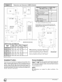
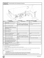
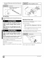
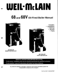
N8MPN& N8MPL
*8MPN& *8MPL
80+Single
Stage
Category
I Furnace
See section
5 for Category
[ definition.
SAFETY
Recognize
safety
to the potential
Understand
words
hazards,
those
CAUTIONis
highlight
install,
Untrained
performed
service
to or shipped
Follow
all safety
safety
These
glasses
es.
We require
personnel.
gloves.
cover
certain
these
International
Lewisburg,
you see this symbol
on the furnace
and in instruction
manuals
be alert
personal
that could
words
or death.
result
installation,
can be hazardous
These
injury
in minor
reliability,
are used with the safety-alert
symbol.
DANGER
identifies
the
WARNINGsignifiesahazardthatcouldresultinpersonalinjuryor
personal
injury
or product
and property
damage.
Note is used to
or operation.
due to gas and electrical
components.
Only trained
and qualified
personnel
should
equipment.
minimum
States,
Comfort
functions
working
on heating
safety
precautions
follow
Standard
all safety
requirements
as a minimum
Products,
available
LLC
TN 37097
as cleaning
observe
including
the National
Gas and Propane
start-up
to existing
those
and replacing
precautions
air filters.
All other
in the literature,
operations
on tags,
must be
and on labels
at-
may apply.
during
especially
for a safe
that
Natural
and conform
and ordinances,
such
equipment,
codes
of Canada
Have fire extinguisher
local codes
instructions
basic maintenance
When
and other
In the United
and work
exceed
practices
in enhanced
refer to the National
instructions
instructions
unsafe
with the furnace
codes.
When
or CA UTION.
in severe
can perform
service
In Canada,
WARNING,
equipment
heating
personnel
by trained
tached
54-2002.
heating
or service
symbolZl._.
result
that will result
and servicing
repair,
DANGER,
that will
used to identify
suggestions
Installing
This is the safety-alert
REQUIREMENTS
injury.
the signal
most serious
death.
information.
for personal
* Denotes Brands (C, H, T)
Fuel Gas Code
Installation
and adjustment
national
standards
Code
(NFGC)
procedures
and safety
ANSI
(NSCNGPIC)
and service
codes.
that may not have kept up with changing
Z223.1-2002/NFPA
CSA B149.1-05.
In some
residential
Wear
calls.
instances,
construction
these
practic-
installation.
INSTALLER:
Affix these instructions
on or adjacent
to the furnace.
CONSUMER:
Retain these
instructions for future reference.
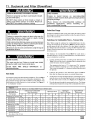
Table of Contents
1. Safe Installation Requirements ................
2. Installation ...............................
3
4
3. Side Venting ..............................
4. Combustion & Ventilation Air .................
5. Gas Vent Installation .......................
8
9
11
6. Horizontal Venting .........................
7. Masonry Chimney Venting ...................
8. Gas Supply and Piping .....................
13
15
18
ELECTRIC SHOCK HAZARD
Failure to follow safety warnings
exactly could result in serious
injury and/or death.
Turn Off All Power Before
Servicing.
9. Electrical Wiring ............................
10.Ductworkand Filter (Upflow/Horizontal) ..........
11.Ductwork and Filter (Downflow) ................
21
22
25
12.Checksand Adjustments......................
13. FurnaceMaintenance ........................
27
32
14.Sequence of Operation& Diagnostics............
TechSupport and Parts..........................
34
35
CARBON MONOXIDE POISONING AND FIRE
HAZARD.
Failure to follow safety warnings exactly could
result in serious injury, death, and/or property
damage.
This furnace is not designed for use in mobile
homes, trailers or recreational vehicles.
Portions of the text and tables are reprinted from NFPA 54 / ANSI Z223,1-2002©,
with permission of National Fire Protection Association, Quincy, MA 02269
Washington, DC 20001. This reprinted material is not the complete and official position of the NFPA or ANSI, on the referenced subject, which is represented
Printed
inU.S.A.
11/10/2005
and American Gas Association,
only by the standard in its entirety,
441 01 2613 (02)
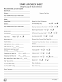
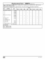
START-UP
(Keep
Recommended,
Dealer
but
not
this
page
CHECK
for future
SHEET
reference)
required,
Name:
Address:
City,
Business Card Here
Zip or Postal Code:
State(Province),
Phone:
Owner
Name:
Manual Gas Shut-Off Upstream
Address:
City, State(Province),
Zip or Postal
Code:
of Furnace/Drip- Leg?
YES_I
NO_I
Drip-Leg Upstream of Gas Valve?
YES_I
NO_I
Blower Speed Checked?
NO [_I
YES _1
Model Number:
YEs_I
All Electrical Connections Tight?
Serial Number:
NO[31
Gas Valve turned ON?
YES _1
NO[_I
Blower Motor H. P,:
Measured
When
Firing
Unit:
Supply Voltage:
Calculated
Checks
and
Type of Gas:
Natural:
Limit Opens at...(°F)
_1
LP:
_1
Line Pressure
Firing
Rate:(See
Adjustments
Section).
or(°C).
Limit Closes at,,,(°F)___or(°C)
Measured Manifold Pressure:
Which blower speed tap is used?
Thermostat OK?
YES _1
NOE_
Subbase Level?
YES _1
NOE_I
Anticipator Set?
YES _1
NO E_ Set At?:
(Heating)
(Cooling).
Temperature of Supply Air:
(°F)___or(°C)
Temperature of Return Air:
(°F)
Rise (Supply Temp.-Return
Temp.): (°F)
or(°C)__
or(°C)__
Breaker On?
YES _1
NoE_I
Filter Type and Size:
Fan "Time ON" Setting:.
Fan "Time OFF" Setting:
Date of Installation:
Date of Start-Up:
Dealer Comments:
441 01 261302
1. Safe Installation
Requirements
FIRE, EXPLOSION, AND ASPHIXIATION
HAZARD
Improper
adjustment,
alteration,
service,
maintance
or installation
could cause death,
personal injury, and/or property damage.
Installation or repairs made by unqualified persons
could result in hazards
to you and others.
Installation MUST conform with local codes or, in
the absence of local codes, with codes of all
governmental authorities having jurisdiction.
The information
contained
in this manual is
intended for use by a qualified service agency that
is experienced
in such work, is familiar with all
precautions
and safety procedures
required in
such work, and is equipped with the proper tools
and test instruments.
•
Provide adequate
nace as specified
these instructions.
Combustion
products
must be discharged
A.
outdoors.
Always install furnace to operate within the furnace's
intended temperature-rise
range with a duct system which
has an external static pressure within the allowable range,
as specified
in "Technical
Support Manual"
of these instructions.
See furnace rating plate.
•
When a furnace is installed so that supply ducts carry air
circulated
by the furnace to areas outside the space containing the furnace, the return air shall also be handled
duct(s) sealed to the furnace casing and terminating
side the space containing
the furnace.
•
A gas-fired
furnace for installation
in a residential
must be installed as specified
in "2. Installation"of
instructions.
441 01 2613 02
Seal around
supply
•
Install
•
Unit MUST be installed so electrical components
tected from direct contact with water.
and return
in mo-
air ducts.
filter type and size.
many years
are pro-
of safe and dependable
The U.S. Consumer
Product Safety Commission
encourages
installation
of carbon monoxide
alarms. There can be various
gas produced when fuel is not burned completely
flame does not receive sufficient oxygen.
injury and/or
and odorless
or when the
Therefore,
to help alert people of potentially dangerous
ca rbon
monoxide
levels, you should have a commercially
available
carbon monoxide
alarm that is listed by a nationally
recognized testing agency in accordance
with Underwriters
Laboratories Inc. Standard
for Single and Multiple Station Carbon
Monoxide
Alarms, ANSI/UL
2034 or the CSA 6.19-01
Residential Carbon Alarming Devices installed and maintained
in
the building or dwelling concurrently
with the gas- fired furnace
installation
(see Note below). The alarm should be installed as
recommended
by the alarm manufacturer's
installation
instructions.
B.
There can be numerous
sources of fire or smoke in a building
or dwelling.
Fire or smoke can cause serious
bodily injury,
death, and/or property
damage.
Therefore,
in order to alert
people of potentially da ngerous fire or smoke, you should have
fire extinguisher
and smoke alarms listed by Underwriters
Laboratories
installed and maintained
in the building or dwelling
(see Note below).
Note:
The manufacturer
of your furnace does not test any alarms
and makes no representations
regarding any brand or type
of alarms.
C.
To ensure safe and efficient
do the following:
1.
Thoroughly
read this manual
and labels on the unit. This
will help you understand
how your unit operates and the hazards involved with gas and electricity.
2.
Do not use this unit if any part has been under water. Immediately call a qualified service agency to inspect the unit and
to replace any part of the control system and any gas control
which has been under water.
3.
Never obstruct
the vent grilles,
or any ducts that provide
air to the unit. Air must be provided for proper combustion
and
ventilation
of flue gases.
by a
out-
garage
these
•
Carbon
monoxide
can cause serious
bodily
death. Carbon monoxide
or "CO" is a colorless
Con-
Never test for gas leaks with an open flame. Use a commercially available soap solution made specifically
for the
detection of leaks to check all connections,
as specified in
"8. Gas Supply and Piping, Final Check"of
these instructions.
is NOT approved
for installation
trailers
or recreation
vehicles.
of
sources of carbon
monoxide
in a building
or dwelling.
The
sources
could be gas-fired
clothes
dryers,
gas cooking
stoves, water heaters,
furnaces,
gas-fired
fireplaces,
wood
fireplaces.
as speci-
vent system only, as spe6. Horizontal
Venting and
these instructions.
This furnace
bile homes,
correct
heating
service providing
it is properly installed and maintained.
However,
abuse and/or improper
use can shorten
the life of the unit and
create hazards for you, the owner.
combustion
and ventilation air to the furin "4. Combustion
and Ventilation Air" of
nect this furnace to an approved
cified in "5. Gas Vent lnstallation,
7. Masonry
Chimney
Venting"of
•
Your unit is built to provide
Use only the Type of gas approved
for this furnace
(see
Rating Plate on unit). Overfiring
will result in failure of heat
exchanger
and cause dangerous
operation.
(Furnaces
can be converted
to LP gas with approved
kit.)
Install this furnace only in a location and position
fied in "2. Installation"of
these instructions.
This furnace
is not to be used for temporary
buildings or structures
under construction.
See "2. Installation, Item 10'_
Safety Rules
NOTE: This furnace is design-certified by the CSA International
(formerly AGA and CGA) for installation in the United States and
Canada. Refer to the appropriate codes, along with this manual,
for proper installation.
•
•
operation
of your unit, you should
[_
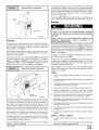
Frozen Water Pipe Hazard
Ifyourfurnace
home
could
remains off for an extended time, the pipes in your
freeze and burst, resulting
in serious water damage.
If the structure will be unattended
take these
precautions.
FROZEN
AND BURST WATER
you should
Turn off the water supply to the structure and drain the water
lines if possible and add an antifreeze
for potable water to
drain traps and toilet tanks. Open faucets in appropriate
areas.
Do not leave your home unattended for long periods
during freezing weather without turning off water
supply and draining
water pipes or otherwise
)rotecting
against the risk of frozen pipes and
resultant damage.
-or-
Have someone
check the structure
frequently
during cold
weather to make sure it is warm enough to prevent pipes
from freezing. Instruct them on a service agency to call to
provide service, if required.
Your furnace is designed
solely to provide a safe and comfortable
living environment.
The furnace is NOT designed
to ensure that
-or-
water pipes will not freeze. It is equipped
with several safety devices that are designed
to turn the furnace off and prevent it from
in the event of various
cold weather
PIPE HAZARD
Failure to protect against the risk of freezing could
result in property damage.
restarting
during
potentially
unsafe
3.
Install a reliable
conditions.
remote
body of freezing
sensing
conditions
device that will notify some-
within
the home.
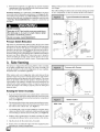
2. Installation
4.
Install the vent pipes as short as practical.
Installation
section).
CARBON MONOXIDE POISONING HAZARD.
5.
Failure
to
appliances
Do NOT install furnace directly on carpeting, tile or other combustible material other than wood flooring.
6.
Maintain clearance
for fire safety and servicing. A front clearance of 24" is minimum for access to the burner, controls and
properly
vent
this
could result in death
furnace
or other
or personal
injury.
If this furnace
is replacing
a previously
commonvented furnace,
it may be necessary
to resize the
existing
vent
system
to
prevent
oversizing
problems
for the other
remaining
appliances(s).
See Venting and Combustion
Air Check in the 5. Gas
Vent Installation
section
of this instruction.
filter. See clearance
Location and Clearances
If furnace is a replacement,
it is usually best to install the furnace
where the old one was. Choose the location or evaluate the existing location based upon the minimum
mensions
(Figure
1 or Figure 2).
clearance
and furnace
di-
CARBON MONOXIDE POISONING HAZARD.
Failure to follow
death or personal
safety warnings
injury.
could
result
7.
Use a raised
8.
Residential
Install
furnace
2.
This furnace
or structures
3.
Install furnace as centralized
heat distribution
system.
as practical
5. Gas Vent
1 or Figure
2.
or wet at times.
require:
Furnace
possible
installed
at least
must be located or physically
damage by a vehicle.
18" (457
protected
from
If the furnace is to be suspended
from the floor joists in a basement or a crawl space or the rafters in an attic, it is necessary to
use steel pipe straps or an angle iron frame to attach the furnace. These straps should be attached to the furnace bottom
side with sheet metal screws and to the rafters or joists with
bolts. The preferred
method
is to use an angle iron frame
bolted to the rafters or joists.
may be used for construction
heat provided
that:
•
The furnace is permanently
installed with all electrical
wiring, piping, venting and ducting installed according
to
these installation
instructions.
A return air duct is provided, sealed to the furnace casing, and terminated
outside the space containing
the furnace.
This prevents a
negative pressure condition as created by the circulating
air blower, causing a flame rollout and/or drawing combustion products into the structure.
•
The furnace is controlled
by a thermostat.
It may not be
"hot wired" to provide heat continuously
to the structure
without thermostatic
control.
•
Clean outside air is provided for combustion.
This is to
minimize the corrosive effects of adhesives,
sealers and
other construction
materials.
It also prevents the entrainment of drywall dust into combustion
air, which ca n ca use
fouling and plugging of furnace components.
level.
is NOT to be used for temporary
under construction.
installations
•
Installation Requirements
1.
if the floor is damp
Burners and ignition sources
mm) above the floor.
Do NOT operate
furnace
in a corrosive
atmosphere
containing
chlorine, fluorine or any
other damaging chemicals which could harm the
furnace and vent system, and permit spillage of
combustion products into an occupied space.
Refer to 4. Combustion
& Ventilation Air section,
Contaminated
Combustion
Air for combustion
air
evaluation and remedy.
in Figure
•
10. This furnace
in
base
garage
requirements
(See
heat of buildings
with respect
to the
•
The temperature
tained between
of the return air to the furnace is main55 ° F (13 ° C) and 80 ° F (27 ° C), with no
evening setback
or shutdown.
The use of the furnace
while the structure
is under construction
is deemed to be
intermittent
operation
per our installation
instructions.
441 01 261302
The air temperature
rise is within
the rated rise range
•
on
The filters
used
construction
oughly
to clean
process
cleaned
the
must
prior
circulating
be either
air during
changed
the
•
or thor-
to occupancy.
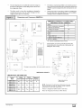
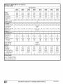
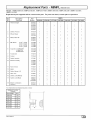
Dimensions
and Clearances
The furnace,
ductwork
and filters are cleaned
as neces-
sary to remove drywall dust and construction
debris from
all HVAC system components
after construction
is completed.
the furnace rating plate, and the firing rate has been setto
the rating plate value.
Verify proper furnace operating
conditions including ignition, gas input rate, air temperature
rise, and venting according to these installation
instructions.
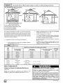
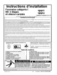
(N8MPN/L)
MINIMUM
CLEARANCES
MATERIALS
TO COMBUSTIBLE
FOR ALL
FURNACES
REAR
0
FRONT (combustion air openings
in furnace and structure)
3"
Required For Service
"24" Min.
*24"
ALL SIDES Of SUPPLY PLENUM
1"
SIDES
0
VENT
61/2
Single-Wall
Vent
6"
Type B-1 Double-Wall
TOP OF FURNACE
LEFT SIDE
Vent
1"
1"
"30" clearancerecommendedfor furnaceremovaL
_-,__--
33/4
A
--
Horizontalposition: Line contactis permissibleonly betweenlines
formed by intersectionsof top andtwo sidesof furnacejacket, and
buildingjoists, studsor framing.
B--
FRONT
21/4
•
Plugged starting
I
hole to cut side
--
2
13114_1_ o_
/1
I
47/8
RIGHT SIDE
®
265/8
C__
-18112 -
11/2
21314
I
I
F-_
'°pening
17/8 _
281/2
33/4 I,,_
BOTTOM
Drawing
I_
is representative,
but some
models
1_
41116
DIMENSIONS
DIMENSIONAL
Furnace
Model
may vary
IN INCHES
11124,10 213,4
INFORMATION
A
Cabinet
B
13t/4
/
Bottom
265/8
ReturnAir
C
D
13/8
125i8
sideductopening
Opening
Plugged starting
holetocut
N8MPN/L05OB12
NSMPN/L075B12
151/2
N8MPN/LO75F16
N8MPN100F14
N8MPN/L1OOF20
19118
175/8
21/8
143/4
N8MPN/L1OOJ22
N8MPN/L125J20
NSMPN/L125J22
NOTE: Evaporator
"A" coil drain pan dimensions
from furnace duct opening
size. Always consult
specifications
for duct size requirements.
22314
21114
115116
183/4
Furnace
441 O1 261302
14
Return
is designed
air through
for bottom
back
return
of furnace
may vary
evaporator
25-23-44al
or side return.
is NOT
allowed.
[_
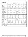
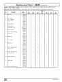
Dimensions
and Clearances
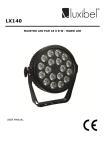
(*8MPN/L
Models)
MINIMUM
CLEARANCES
MATERIALS
TOP
TO COMBUSTIBLE
FOR ALL
UNITS
REAR
0
FRONT (combustion air openings
in furnace and structure)
3"
5113
Required For Service
*24"
_E
"24"Min.
ALL SIDES Of SUPPLY PLENUM
1"
SIDES
0
VENT
LEFT SIDE
Single-Wall
--
3314
5f__ _ _1
--A_
--
•
Plugged starting
I
hole to cut side
7/8
38
Vent
6"
Type B-1 Double Wall Vent
TOP OF FURNACE
B
1"
1"
"30" clearancerecommendedfor furnaceremoval.
--
Horizontalposition: Line contactis permissibleonly betweenlines
formed by intersectionsof top andtwo sidesof furnacejacket, and
buildingjoists, studsor framing.
FRONT
1
28112
2-131/4
_¢t
opening
21814
17/8/
47/
11/2
RIGHT SIDE
26518
®
L
1
37
Drawing
I_
is representative
Furnace
I
models
H
29,1121
3_
IN INCHES
11751
INFORMATION
Cabinet
I Top
Bottom
I ReturnAir
11/2
*8MPN/LOSOB12
*8MPN/LO75B12
Mode,
I;I 2
_4
*8MPN/L075F16
*8MPN100F14
1911817518
*8MPN/L10OF20
40
J
/41I
may vary
41116
DIMENSIONS
DIMENSIONAL
some
6
F
1318
C
12518
D I
H
Opening
73/4
21/8
14314I
J
*8MPN/LIOOJ20
I
47/8
L
l
13114
T
13/4
17/8
265/_
NOTE: Evaporator "A" coil drain pan dimensions may
vary from furnace duct opening size. Always consult
evaporator specifications for duct size requirements.
Furnace is designed for bottom return or side return.
Plugged starting hole to
cut side duct opening
Return air through back of furnace is NOT allowed.
*8MPN/L125J208MPN150J20
223/4211/4
91/2
115116 183/4
J
* Denotes Brand
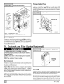
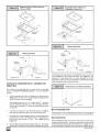
Installation Positions
This furnace can be installed in an upflow, horizontal
(either left or
right) or downflow
airflow position. DO NOT install this furnace on
its back. For the upflow position, the return air ductwork can be attached to either the left or right side panel and/or the bottom. For
horizontal and downflow positions, the return air ductwork must be
attached to the bottom. The return air ductwork must never be attached to the back of the furnace.
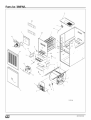
Furnace Installation
Inspect
the rating plate to be certain
the model number
begins
with
"N8MP" or "*8MP".
This identifies the unit as a multi-position
furnace and can be Installed in a Upflow, Horizontal
Right, Horizontal
Left or Downflow
position.
Dentoes Brand (C, H, T)
Upflow
No modifications
Figure 3)
are
required
for
upflow
installation.
(See
441 O1 261302
The horizontal
iiiiiiiiiiiiiiiii_!!!!!!!!:!i:iil
¸;i
¸ii
¸ii
¸ii
¸ii
¸ii
¸ii
¸ii¸i
¸ii
¸ii
¸ii
¸iiiiliiiiii;;;iiiiiiii;i;il;i;i;i;iiii_ilili;i;i;i;;i;i;il;i;iiiii
¸i;iiiii!!!
furnaces
may be installed
directly
i!i!i!i!i!i!i!i!i!i!i!
ii i ! i ! i!!
T p,ca,
ii!i!!i!iiii!
iUp.ow
i i i ,nsta.at,on
iiiiiiiiiiiiiiiiiiiiiiiiiiiiiiiiiiiiiii i i i i i
on combustible
wood flooring or supports, however, it is recommended
for further
fire protection cement board or sheet metal is placed between the
furnace and the combustible
wood floor and extend 12" beyond
the front of the furnace louver door. (This is a recommendation
SUPPLY
AIR
only, not a requirement).
RETURN
This furnace MUST NOT be installed directly on carpeting,
tile or
other combustible
material other than wood flooring or supports.
N
Downflow
FIRE HAZARD.
GAS SUPPLY
Failure to install unit on noncombustible
subbase
could result in death, personal injury and/or property
damage.
25-23-17
Place furnace
on noncombustible
subbase
on
downflow
applications,
unless
installing
on
noncombustible
flooring.
Horizontal
If you purchased
a multi-position
furnace,
it can be installed
hori-
zontally in an attic, basement, crawl space, alcove, or suspended
from a ceiling in a basement or utility room in either a right or left
airflow position. (see Figure 4)
Horizontally
installed furnaces
may be vented
unit or out the side facing u p. See"Side
venting"
rotate the vent to the side.
The minimum
clearances
between
furnace
the
to combustibles
and
adjacent
out the top of the
for instructions
to
MUST
as
shown
between
Figure
in
Figure 1 and Figure 2. ONLY the corner of the cabinet is allowed
to contact the rafters as shown in Figure 4. All other clearances
MUST be observed
as shown in Figure 1 and Figure 2.
A subbase
is installed
furnace
and
adjacent
Installation
construction,
for combustible
as a downflow
installing
as shown
in
2.
1 and Figure
a four-position
(not the *8DNL furnace),
rightside-up
as follows:
2, clearance
for
floors MUST be used when the furnace
on combustible
material. See 11. "Duct-
work and Filter" (Downflow
Section).
bent flat for downflow
installation.
When
Typical Horizontal
the
1 and Figure
In addition to clearances
in Figure
the vent pipe must be considered.
be maintained
construction,
If you purchased
a Multi-position
furnace (N8MP or *8MP) it may
be installed in a downflow
configuration,
(see Figure 5). The minimum clearances
to combustion
construction
MUST be maintained
The outlet
furnace
flange
must
in the downflow
the logo is to be repositioned
be
position
so that it is
T8MPN/L
SUPPLY
1.
Find the door hardware
save it.
2.
Carefully remove logo from the outside
door and save it.
3.
Carefully remove two small plug buttons
er compartment
door and save them.
from outside
of blow-
4.
Remove
compartment
door.
5.
Install
two thumbscrews
kit that is stored
in the furnace
and
of burner compartment
from blower
GAS SUPPLY
two
thumbscrews
compartment
in holes
door from where
at other
thumbscrews
end
of
blower
were removed.
6.
Install new strip of rubber gasket on inside of blower compartment door on edge that does not already have a gasket.
7.
Install logo retainer pins into holes in blower
from which plug buttons were removed.
8.
Install plug buttons into holes in burner compartment
which logo was removed.
metal screws and to the rafters or joists with bolts. The preferred
method is to use an angle iron frame bolted to the rafters or joists.
9.
Install blower compartment
and logo at top.
If the furnace is to be installed
sult local codes. A concrete
10. Install burner
bottom.
OPTIONAL
VENT LOCATION
25- 23-18a
If the furnace
is to be suspended
from the floor joists
in a basement
or crawl space or the rafters in an attic, it is necessary
to use steel
pipe straps or an angle iron frame to attach the furnace.
These
straps should be attached to the furnace bottom side with sheet
at ground level in a crawl space, conpad 1" to 2" thick is recommended.
Twenty four inches (24") is required between the front of the furnace and adjacent
construction
or other appliances.
This should
be maintained
for service clearance.
Keep all insulating
materials
materials
may be combustible.
441 01 2613 02
clear from Iouvered
door. Insulating
N8MPN/L,
compartment
C81VlPN/L,
Carefully
save it.
2.
Turn the logo rightside-up,
in burner
door on furnace
door
door from
with bevel
edge
with bevel edge at
H8MPN/L
1,
into holes
remove
door on furnace
compartment
logo from
burner
compartment
and install
compartment
door.
door
the logo retainer
and
pins
3. Newlabelsforrightside-up
application
onoutside
ofblower
compartment
doormaybepurchased
inakitfromyourdistributortocoverupside-down
labels.
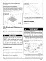
Downflow
Venting:
Thecombustion
venterMUSTberotated
to
ventoutthesideforalldownflow
installations,
(seeFigure5).Bottomventing
isnotpermitted.
See"Side
venting"forinstructions
to
rotate
theventtotheside.Inaddition
torotating
theventtotheside
a VentPipeShield(NAHAOO2VC)
is required
toshieldthehot
ventpipe.
kinking
of the pressure
switch
hose, trim the hose to remove
ex-
cess length.
Note: When drilling new holes make sure metal shavings do not fall
on or in components,
as this can shorten the life of the furnace.
Typical Downflow
Installation
RETURN
AIR
BURN HAZARD.
Vent pipe is HOT and could cause personal injury.
Hot vent pipe is in reach of small children when
installed in downflow position.
See side venting
Install vent pipe shield NAHA002VC.
Combustible
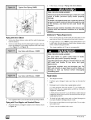
Pressure Switch Relocation
base outlet
adapter
floor
flange
If the furnace is installed in the u pflow position, the pressure switch
will remain in the same position as installed by the factory unless
the inducer is rotated. If the furnace is installed in an orientation
that places
the pressure
switch
below
the pressure
tap on the in-
Vent Shield
Kit
MUST BE OPPOSITE
VENT DISCHARGE
SIDE
ducer housing, then the switch MUST be relocated.
In order to relocate the switch, locate 2 mounting holes or drill above the inducer
pressure
tap. When drilling the 2 holes make sure to keep the
switch and tubing far enough away from the burners or hot surfaces as to not melt the hose, switch,
or wires.
To prevent
SUPPLY
AIR
25-23-19
possible
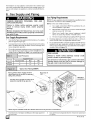
3. Side Venting
This furnace
is shipped
from the factory
with the venter
assembly
Furnace with Screws
in an upflow configurations
(top vent). The venter assembly
can
easily be rotated to a side vent configurations
for use in upflow,
horizontal-flow,
or downflow
application.
When using a side vent configuration
(side outlet instead of top
outlet), it may be necessary
to relocate the pressure switch to the
alternate position on the opposite side of the top panel. Two screw
holes are provided at the alternate
position.
Route the pressure
switch tubing so the tubing is not kinked and not touching
the hot
collector
box, venter housing,
or motor.
It may be necessary
to
shorten the length
eliminate
kinks.
of the tubing
to properly
route
the tubing
and
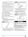
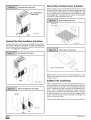
Rotating the Venter Assembly
1,
(see Figure
the venter
3,
Venter
6).
Disconnect
power leads to the venter motor and hose to pressure switch. Remove three (3) or four (4) screws which secure
to the collector
Cut webbing
box, (see Figure
with a pair of snips holding
(2)
25-23-45
If gas and electrical
power have already been connected
to
unit shut off gas and remove power from unit. Unscrew screws
on burner compartment
door and remove burner compartment
door.
2,
Screws
Main Line
Gasket
Entry
7).
the vent plate to the
cabinet on either the left or right side of unit depending
on right
or left venting as desired. Discard vent plate, (see Figure 6).
4,
Replace venter gasket (part # 1013540,
if needed) to venter
assembly with adhesive
in the same location as the old one.
5.
Clip the wire tie for the venter
6.
Rotate venter assembly
90 ° right or left from original
depending
on venting configurations.
wires,
if needed.
25-23-52c
25-23-52b
location
441 01 2613 02
7.
Tighten
the three
assembly
compress
8.
(3) or four (4) screws
to the collector
venter gasket.
Replace
pressure
power leads
switch.
that secure
box. Do tighten
to venter
4. Combustion
motor
the venter
screws
enough
and reconnect
to
hose to
& Ventilation
NOTE: Unused open vent hole must be covered. A Vent Cover is
supplied with Vent Pipe Shield Kit NAHAOO2VC.
A 55/16" diameter
Vent Cover is available separately
from your distributor, or one can
be fabricated
with sheet metal for all side vent installations.
Air
CARBON MONOXIDE POISONING HAZARD.
Failure
to provide
ventilation
air could
injury.
adequate
combustion
and
result
in death or personal
Use
methods
described
combustion
and ventilation
here
air.
to
•
Cleaning
•
Printing
solvents
(such as perchloroethylene).
•
•
Hydrochloric
acid.
Sulfuric Acid.
inks, paint removers,
•
Solvent
•
Antistatic
cements
fabric
•
Masonry
acid washing
varnishes,
etc.
and glues.
softeners
for clothes
dryers.
materials.
provide
Outdoor Combustion
A space
having
Air Method
less than 50 cubic feet per 1,000 BTUH input rating
Furnaces
require ventilation
openings
to provide sufficient air for
proper combustion
and ventilation
of flue gases. All duct or open-
for all gas appliances
installed
combustion
and ventilation.
ings for supplying combustion
and ventilation air must comply
the gas codes, or in the absence of local codes, the applicable
tional codes.
Air Openings and Connecting Ducts
with
na-
1.
Combustion
and ventilation
air must be supplied
in accordance
in the space
Total input rating for all gas appliances
considered
when
determining
requires
outdoor
in the space
air for
MUST
be
free area of openings.
with one of the following:
1.
Section
8.3, Air for Combustion
Fuel Gas Code,
in the U.S.,
2.
(NFGC),
and Ventilation,
ANSI
Z223.1-2002/NFPA
54-2002
Sections 7.2, 7.3, 7.5, 7.6, 7.7, and 7.8 of National Standard of
Canada, Natural Gas and Propane Installation Code
(NSCNGPIC), CSA B149.1-05 in Canada,
3.
Applicable
provisions
of the local building
Installations
Combustion
in certain areas or types of structures
The following
areas or types of structures
could
cause ex-
chemicals
or halorelated problems
must use only out-
may contain
Commercial
•
Buildings
with
•
Furnaces
installed
in laundry
•
Furnaces
installed
in hobby
•
•
Furnaces
installed near chemical storage
Permanent
wave solutions for hair.
•
Chlorinated
•
Chlorine
•
Water
•
•
De-icing
salts or chemicals.
Carbon tetrachloride.
•
Halo_erants.
When
MUST
4.
The minimum
indoor
waxes
softening
pools.
screens
are used
be no smaller than
to the outdoors.
dimension
to cover openings,
1/4" mesh.
of air ducts
shall have a mesh size not smaller
MUST
the openings
NOT be less than
than 1/4".
Requirements
1.
Provide
the space
with sufficient
air for proper combustion
Figure 8 illustrates how to provide
air when two permanent
openings,
used.
and
be
air
combustion
and ventilation
one inlet and one outlet, are
a.
One opening MUST commence within 12" of the floor
and the second opening MUST commence within 12" of
the ceiling.
b.
Size openings
c.
Horizontal
duct openings
require 1 square inch of free
2
area per 2,000 BTUH (1,100 mm /kW) of combined input
for all gas appliances
in the space (see Table 1).
d.
Vertical duct openings
or openings
directly communicating with the outdoors
require 1 square inch of free area
2
per 4,000 BTUH (550 mm /kW) for combined
input of all
gas appliances
in the space (see Table 1).
or craft rooms.
pool chemicals.
directly
When sizing a grille, louver or screen use the free area of opening. If free area is NOT stamped
or marked on grill or louver,
assume a 20% free area for wood and 60% for metal. Screens
rooms.
and cleaners.
swimming
or openings
3 '_ .
buildings.
based
441 01 2613 02
3.
or have ex-
posure to the substances
listed below. The installation
must
evaluated
carefully as it may be necessary
to provide outdoor
for combustion.
•
ducts
ventilation of flue gases using horizontal or vertical ducts or
openings.
Air
cessive exposure to contaminated
air having
gens that will result in safety and performance
and may harm the furnace.
These instances
door air for combustion.
Connect
code.
When the installation
is complete,
check that all appliances
have
adequate
combustion
air and are venting properly. See Venting
And Combustion
Air Check in %. Gas Vent Installation
"Section in
this manual.
Contaminated
2.
of the National
and ducts
per Table
1.
areas.
When one permanent
requires:
outdoor
opening
is used, the opening
a.
1 sq. in of free area per 3,000 BTUH (700 mm2/kW) for
combined
input of all gas appliances
in the space (see
Table 1) and
b.
not less than the sum of the areas of all vent connectors
chemicals.
in
the _space.
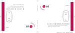
G3
Outside
Air (This
is ONLY
a guide.
SubJect
to codes
of country
having
jurisdiction.)
ThisinstallationNOTapprovedin Canada
GasVent
Vent
G Vent _j_.Gable
, GableV_/)
ba_ventilated
(1)
I
I/
Soffit
Vent
I
1
I_
TM
SoffitVen,
Outlet/1_
_.
F......
Air (1)
€_:;;_l
utletAir (1)
II
Inlet
Attic'_
Top Above Insulation_
Air(1)
NG_
_,,
_
r-_
--
Inlet
Air (2)
Inlet
Air (1)
........
MinimumOne Inlet and One Outlet Air Supply is Required
May be in andCombination Shown
Air (2)
Inlet Air Opening Must beWithin12"(300mm)of floor
Outlet Air OpeningMust be Within12"(300mm)of ceiling
(1) 1 Square Inch (6cm2) per 4000 BTUH
(2) 1 Square Inch (6cm2) per 2000 BTUH
The opening
shall
commence
within
12" of the top of the enclo-
sure. Appliances
shall have clearances of at least 1" from the sides
and back and 6" from the front. The opening shall directly communicate with the outdoors or shall communicate
through a vertical or
horizontal
duct to the outdoors or spaces
communicate
with the outdoors.
4.
Combination
a.
b.
Outdoor
openings
located as required
Combustion
air Method above and
c.
Outdoor
that comply
below and
with the Indoor
sized
as follows.
1) Calculate the Ratio of all Indoor Space volume divided by required volume for Indoor Combustion
Air Method. Outdoor openings
sized as follows.
(crawl or attic) that freely
2) Outdoor opening
Ratio in 1) above.
of Indoor and Outdoor Air shall have:
Indoor openings
tion Air Method
openings
in the Outdoor
size reduction
Factor
is I minus the
3) Minimum
size of Outdoor openings
shall be the size
required
in Outdoor
Combustion
Air Method above
multiplied
by reduction
Factor.
Combus-
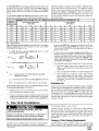
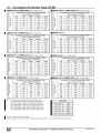
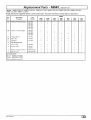
FreeArea
BTUH
MinimumFree Area Required for EachOpeningor Ductto Outdoors
Input
Rating
Two HorizontalDucts
(sq.inJ2,000 BTUH)
SingleOpening
(sq. in./3,000BTUH)
TwoVertical Ductsor Openings
(sq.inJ4,000 BTUH)
Round Duct
(sq. in./4,000
BTUH)
50,000
25 sq, in.
75,000
37,5 sq. in.
16.7sq. in.
12,5sq. in.
4"
25 sq, in,
18.75sq. in.
100,000
5"
50 sq. in.
33.3 sq. in.
25 sq. in,
6"
125,000
62,50 sq. in.
41,7 sq. in.
31.25sq, in.
7"
150,000
75 sq, in.
50 sq, in,
37,5 sq. in.
7"
EXAMPLE:
Determining
Free Area
Furnace
100,000
+
Furnace
100,000
+
Indoor Combustion
Water Heater
Total Input
30,000
(130,000 + 4,000)
Water Heater
Total Input
30,000
(130,000 + 2,000)
32.5 Sq. In. Vertical
65 Sq. In. Horizontal
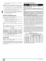
Air
Standard and Known-Air-Infiltration
Rate Methods
CARBON MONOXIDE POISONING HAZARD.
© NFPA & AGA
Indoor
air is permitted
for combustion
and ventilation,
if the
Standard
or Known-air-lnfiltration
Rate Method is used,
Failure to supply adequate combustion
result in death or personal injury.
air could
Most homes will require additional air from outdoors
for combustion and ventilation. A space with at least
50 cubic feet per 1,OOOBTUH input rating or homes
with tight construction
may need outdoor air to
supplement
air infiltration
for proper combustion
and ventilation of flue gases.
441 O1 261302
The Standard
Method
may be used, if the space
has no less vol-
(ACH)
and equal
to or greater
than
0.10 ACH.
ume than 50 cubic feet per 1,000 BTUH of the maximum
input ratings for all gas appliances
installed in the space.
The standard
method permits indoor air to be used for combustion
and ventilation air.
greater
than 0.60 ACH shall not be used.
volume
of the space
The Known
add the volumes
filtration
Air Infiltration
rate is known
Rate
Method
to be less than
determined
minimum
shall be used if the in-
0.40 air changes
per hour
varies
per Table
required
with the number
2 or Equations
volume
together
Infiltration
The minimum
rates
required
of ACH and shall be
1 and
2.
for each appliance
Determine
the
in the space,
and
to get the total minimum
required
vol-
ume for the space.
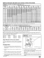
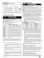
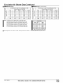
MINIMUMSPACEVOLUMEFOR100%COMBUSTIONANDVENTILATIONAIR FROMINDOORS (ft 3)
Other Than Fan-Assisted Total
.............................................................. (1,OOO's
Btuh)
ACH
30
40
Fan- assistedTotal
(1,000'sBtuh)
50
50
75 I
100
125
I
180
0.60
1,050
1,400
1,750
1,250
1,875
2,500
3,125
3,750
0.50
1,260
1,680
2,100
1,500
2,250
3,000
3,750
4,500
0.40
1,575
2,100
2,625
1,875
2,813
3,750
4,688
5,625
0.30
2,100
2,800
3,500
2,500
3,750
5,000
6,250
7,500
0.20
3,150
4,200
5,250
3,750
5,625
7,500
9,375
11,250
0.10
6,300
8,400
10,500
7,500
11,250
15,000
18250
22,500
0.00
NP
NP
NP
NP
NP
NP
NP
NP
NP = Not Permitted
Table 2 Minimum Space Volumes were determined by using the
following equations from the National Fuel Gas Code ANSI
Z223.1/NFPA 54-2002, 8.3.3.2:
1.
For other
than fan-assisted
hood-equipped
water heater,
Volume other =
2.
21 ft 3
ACH
For fan-assisted
Volume fan =
(
appliances
I other
1000 Btu / hr
appliances
15ft3
ACH
(
such
such
as a draft
In spaces that use the Indoor
Combustion
Air Method, infiltration should be adequate
to provide air for combustion,
ventilation
and dilution of flue gases. However,
in buildings
with unusually tight construction,
additional air MUST be provided using the methods described
in section titled Outdoor
Combustion
Air Method:
)
as this furnace,
Iran
1000 Btu / hr
Unusually
)
If:
[ other= combined input of all other than fan-assisted
appliances in Btu/hr
[fan = combined
input of all fan-assisted
appliances
in Btu/hr
ACH = air changes per hour (ACH shall not exceed 0.60.)
The following
requirements
the Known
Air Infiltration
apply to the Standard
Rate Method.
Method
and to
•
Adjoining
rooms can be considered
part of a space,
are no closable doors between
rooms.
•
An attic or crawl space may be considered
a space that freely
communicates
with the outdoors provided there are adequate
ventilation
openings directly to outdoors.
Openings MUST re-
5. Gas Vent
main open and NOT have any means of being closed off. Ventilation openings
to outdoors
MUST be at least 1 square inch
of free area per 4,000 BTUH of total input rating for all gas appliances in the space.
if there
tight construction
is defined
as Construction
with:
1.
Walls and ceilings exposed to the outdoors have a continuous, sealed vapor barrier. Openings are gasketed
or
sealed and
2.
Doors
3.
Other openings
are caulked or sealed. These include
joints
around window
and door frames,
between
sole
plates and floors, between
wall-ceiling
joints, between
wall panels, at penetrations
for plumbing,
electrical and
gas lines, etc.
and openable
windows
are weather
stripped
and
Ventilation Air
Some provincial
codes
and local municipalities
require
ventilation
or make-up
air be brought into the conditioned
space as replacement air. Whichever
method is used, the mixed return air temperature across
the heat exchanger
MUST
not fall below
60 °
continuously,
or 55 ° on an intermittent
basis so that flue gases will
not condense
excessively
in the heat exchanger.
Excessive condensation
will shorten the life of the heat exchanger
and possibly
void your warranty.
Installation
This Category
CARBON MONOXIDE POISONING,
EXPLOSION HAZARD.
FIRE AND
Failure to properly vent this furnace could result in
death, personal injury and/or property damage.
Read and follow all instructions
[ furnace
is fan-assisted.
Category ] furnace definition: A central furnace which operates
with a non-positive vent static pressure and with a flue loss not
less than 17 percent. These furnaces are approved for commonventing and multi-story venting with other fan-assisted or draft
hood-equipped
appliances in accordance with the NFGC or
NSCNGPIC
in this section.
Category I Safe Venting Requirements
Install the vent in compliance
with codes of the country having jurisdiction,
local codes or ordinances
and these instructions.
441 O1 2613 02
Category
] furnace vent installations
shall be in accordance
Parts 10 and 13 of the National Fuel Gas Code (NFGC),
with
ANSI
Z223.1-2002/N
FPA
54-2002;
and/or
Section
7andAppendix
Cof
theCSAB149.1-05,
National
Standard
ofCanada,
Natural
Gas
andPropane
Installation
Code;
thelocalbuilding
codes;
furnace
andventmanufacturer's
instructions.
NOTE: The following instructions
comply with the ANSI
Z223.1/NFPA 54 National Fuel Gas Code and CSA B149.1 Natural Gas and Propane Installation code, based on the input rate on
the furnace rating plate.
1,
If a Category ] vent passes through an attic, any concealed
space or floor, use ONLY Type B or Type L double wall vent
pipe. If vent pipe passes through interior wall, use Type B vent
pipe with ventilated thimble ONLY.
2.
Do NOT vent furnace into any chimney serving an open fireplace or solid fuel burning appliance.
3.
Use the same diameter Category ] connector or pipe as permitted by:
CARBON MONOXIDE POISONING HAZARD
Failure
to follow
the steps
outlined
below
for each
appliance
connected
to the venting
system being placed
into
operation,
could
result
in
carbon
monoxide
poisoning
The following
Fuel Gas Code
Code
/ NFPA 54-2002
sections
ing requirements
in the United
(NFGC)
ANSI
10 and 13 vent-
States
Standard
of Canada
Natural
Gas and Pro-
pane Installation
Code (NSCNGPIC)
CSA B149.1-05
section 7 and appendix C venting requirements
in Canada.
4,
Push
the vent connector
onto
the furnace
flue collar
of the
venter assembly until it touches the bead (at least 5/8" overlap)
and fasten with at least two field-supplied,
corrosion-resistant, sheet metal screws located at least 140 ° apart.
5.
Keep vertical Category
[ vent pipe or vent connector
short and direct as possible.
6.
Vertical outdoor runs of Type-B or ANY single wall vent pipe
below the roof line are NOT permitted.
7.
Slopeallhorizontalrunsupfromfurnacetotheventterminal
minimum of 1/4" per foot (21 mm/m).
8.
9.
runs as
a
Rigidly support all horizontal
portions of theventing
system every 6' or less using proper clamps and metal straps to prevent
sagging and ensure there is no movement
after installation.
Check
ances
existing gas vent or chimney to ensure
and local codes. See Figure 1
they meet clear-
10. The furnace MUST be connected
to a factory built chimney or
vent complying
with a recognized
standard,
or a masonry or
concrete chimney lined with a lining material acceptable
to the
authority
having jurisdiction.
Venting
into an unlined
masonry chimney
or concrete
chimney
is prohibited.
See the
6. Masonry
Chimney
Venting
section
in these instructions.
11. Fan-assisted
not be vented
combustion
system Category
into single-wall
metal vents.
] furnaces
shall
12. Category
] furnaces must be vented vertically or nearly
cally, unless equipped
with a listed mechanical
venter.
verti-
13. Vent connectors
serving Category I furnaces shall not be connected into any portion of mechanical
draft systems operating
under positive pressure.
Venting and Combustion
NOTE:
placed,
When an existing
the original venting
erly vent
adequate
LOWING
/2N
the attached
combustion
CHECK.
shall
Air Check
Category
I furnace is removed
or resystem may no longer be sized to prop-
appliances,
and to make sure there is
air for all appliances,
MAKE THE FOL-
be followed
for each
any unused
openings
appliance
being
placed
into
connected
to the
in the venting
system.
2.Inspect
the venting system for proper size and horizontal
pitch, as required in the National
Fuel Gas Code, ANSI
Z223,1/NFPA
54 or CSA B149.1,
Natural
Gas and
Propane Installation
Code and these instructions.
Determine that there is no blockage or restriction,
leakage, corrosion and other deficiencies
which could cause an unsafe
condition.
3.As far as practical,
or
the National
steps
connected
to the venting
system
operation,
while
all other appliances
venting
system
are not in operation:
1 .Seal
the National
Z223.1-2002
or death:
close
all building
doors
and windows
and all doors between the space in which the appliance(s)
connected
to the venting system are located and other
spaces of the building.
4.Close
fireplace
dampers.
5.Turn on clothes dryers and any appliance not connected
to
the venting system. Turn on any exhaust fans, such as
range hoods
and bathroom
exhausts,
so they are
operating
at maximum
speed. Do not operate a summer
exhaust fan.
6. Follow the lighting instructions.
Place the appliance
inspected
into operation.
Adjust
the thermostat
appliance
is operating
continuously.
being
so
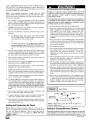
7.Test for spillage from draft hood equipped
appliances
at
the draft hood relief opening after 5 minutes of main burner
operation.
Use the flame of a match or candle. (Figure
9)
8.If improper venting is observed,
during any of the above
tests, the venting system must be corrected
in accordance
with the National Fuel Gas Code, ANSI Z223,1/NFPA
54
and/or
Code.
CSA B149, 1, Natural
Gas and Propane
Installation
9.After it has been determined
that each appliance
connected to the venting system properly vents when tested
as outlined above, return doors, windows,
exhaust fans,
fireplace
appliance
dampers
and any other gas-fired
to their previous
conditions
of use.
burning
Vent Check
Vent Pipe _1
I
A/
Draft Hood
Typical Gas
Water Heater
!
NOTE: If fame pu IIs towar ds dftra
sufficient infiltration
air.
hoJd , this indicates
Venting to Existing Masonry Chimney
Dedicated
venting of one fan assisted
furnace
into any masonry chimney
is restricted.
A chimney must first be lined with
either Type B vent sized in accordance
with NFGC tables 13.1 or
441 01 261302
13.2 or a listed, metal lining system. (See Section
Chimney Venting of these instructions.)
7 Masonry
Listed, corrugated
metallic
chimney
liner systems
in masonry
chimneys shall be sized by using NFGC tables per 13.1.7 for dedicated venting and per 13.2.19 for common venting with the maximum capacity
reduced by 20% (0.80 X maximum
capacity)
and
the minimum capacity
use the NSCNGPIC,
as shown in the applicable
appendix
C, section 10.
table. In Canada,
Corrugated
metal
Combined Venting into a Masonry Chimney
Venting
into a masonry
or concrete
chimney
is only permitted
as outlined in the NFGC or NSCNGPIC
all safe venting requirements.
venting
Note:
Venting".
See section
"7. Masonry
Chimney
tables.
Follow
vent systems installed with bends or offsets require additional
reduction of 5% of the vent capacity for each bend up to 45° and 10%
of the vent capacity for each bend from 45 ° up to 90 ° .
NOTE: Two (2) 45 ° elbows are equivalent to one (1) 90 ° elbow.
6. Horizontal
Venting
Vent Termination
Category I Furnaces With External Power
Venters
In order to maintain
a Category
naces when vented
horizontally
venter
is REQUIRED
] classification
with sidewall
to maintain
a negative
of fan-assisted
termination,
pressure
Venting Through a Non-Combustible
Combustible Wall
fur-
a power
in the vent-
ing system.
Consult
External
In Canada:
Only
power
manufacturer
and where
venters
allowed
approved
by
by the authority
consult
for power
the Fields
venters
441 01 2613 02
certified
Controls
manufacturer
instructions.
included
•
venting
•
vent terminal
•
preventing
•
protecting
•
see Figure
with the power venter
for:
installation,
location,
blockage
by snow,
the appliance
having jurisdic-
tion may be used
Please
Venter
Select the power venter to match the Btuh input of the furnace being vented.
Follow all of the Power Venter manufacturer's
installation requirements
In the U.S.: Per the NFGC, a listed power venter may be used,
when approved by the authority having jurisdiction.
Power
and
Co. or Tjernlund
for use with our furnaces.
Products,
Inc.
building
materials
10 for required
from degradation
by flue gases,
vent termination.
NOTE: It is the responsibility
of the installer to properly terminate
the vent and provide adequate
shielding. This is essential in order
to avoid
water/ice
damage
to building,
shrubs
and walkways.
[_
Other than Direct Vent Termination
iiiiiiiiiiiiiiiiiiiiiiiiiiiii
i i! ii ii ! i ! !iClearance
! ii i i i i i i i i i i i
IVIVENTTERMINAL
Item
A
Clearance
AIRSUPPLVINLET
Descriptions
Canadian
Clearance above grade, veranda, porch, deck, balcony, or
Installation
AREA WHERE TERMINAL
(1)
IS NOT PERMITED
U.S. Installation
(2)
12" (30cm) #
12" (30 cm)
6" (15 cm) for appliances _< 10,000 BTUH (3kW), 12" (30
cm) for appliances > 10,000 Btuh (3 kW) and _<100,000 Btuh
4' (1.2 m) below or to the side of the opening. 1' (30 cm)
anticipated snow level
B
Clearance to a window or door that may be opened
(30 kW), 36" (91 cm) for appliances
C
Clearance to a permanently
9
Vertical clearance to a ventilated soffit located above the ter-
above the opening.
> 100,000 Bluh (30 kW)
closed window
minal within a horizontal distance of 2' (61cm) from the centedine of the terminal
E
Clearance to an unventilated soffit
F
Clearance to an outside corner
G
Clearance to an inside corner
H
Clearance to each side of the centedine extended above elec-
3' (91 cm) within 15' (4.5 m) above the meter/regulator
3' (91
trical meter or gas service regulator assembly
assembly
assembly
I
Clearance to service regulator vent outlet
3' (91 cm)
J
Clearance to non-mechanical
6" (15 cm) for appliances_<10,000BTUH (3kW),12" (30
cm) for appliances> 10,000 Btuh (3 kW) and _<100,000Btuh
(30 kW), 36" (91cm) for appliances> 100,000Btuh (30 kW)
combustion
air supply inlet to building or the
air inlet to any other appliance
K
Clearanceto a mechanical air supply inlet
6' (1.83m)
L
Clearanceunder a veranda, porch,deck, or balcony
12" (30cm) +
M
Clearance to each side of the centedine extended above or
*
4' (1.2
cm)
within
m) below
15'
(4.5
m) above
or to the side
the meter/regulator
of opening:
1' (30 cm)
above
opening,
3' (91
cm)
above
if within
10'
(3m)
horizontally
below vent terminal of the furnace to a dryer or water heater
vent, or other appliance's direct vent intake or exhaust.
N
Clearance from a plumbing vent stack
3' (91 cm)
3' (01cm)
0
Clearance above a paved sidewalk or paved driveway located
7' (2.13 m)
7' (2.13m)
on public properly.
(I.)
InaccordancewiththecurrentCSAB149.1,NaturalGasandPropanelnstaHationCode
(2.)
In accordance
#
18" (46 cm) above roof surface
+
Permitted only if veranda, porch, deck, or balcony is fully open on a minimum of two sides beneath the floor.
For clearances
with the current ANSI Z223.11NFPA 54, Nafional Fuel Gas Code
not specified in ANSI Z223.1/NFPA 54 or CSA B149.1, clearances shall be in accordance
with local installation codes and the requirements
of the gas supplier and the manufacture's
installation instructions.
A vent shall not terminate directly above a sidewalk or paved driveway that is located between two single family dwellings and serves both dwellings.
Notes:
1.
2.
The vent for this appliance shall not terminate
a.
Over public walkways;
b.
c.
Near soffit vents or crawl space vents or other areas where condensate or vapor could create a nusiance or hazard or property damage; or
Where condensate vapor could cause damage or could be detrimental to the operafion of regulators, relief valves, or other equipment.
or
When locating vent terminations,
Recirculafion
consideration
can cause poor combustion,
must be given to prevailing winds, location, and other conditions which may cause recirculation
inlet condensate
problems, and accelerated
of the combusfiob
products of adjacent vents.
corrosion of the heat exchangers.
441 O1 261302
7. Masonry
Chimney
Venting
Chimney Inspection
Ira claytile-lined
All masonry
chimney
construction
must conform
to Standard
ANSI/NFPA
211-2003
and to any state or local codes applicable.
The chimney must be in good condition
and a complete
chimney
to the outdoors
below the roof line, relining might be required.
Chimneys
shall conform
to the Standard
for Chimneys,
Fireplaces, Vents, and Solid Fuel Burning Appliances
ANSI/NFPA
211-2003
in the United States and to a Provincial
or Territorial
inspection must be conducted
prior to furnace installation.
If the inspection
reveals damage or abnormal
conditions,
make necessary repairs or seek expert help. See Figure 11 "The Chimney
Building Code in Canada
(in its absence,
the National
Code of Canada) and must be in good condition.
Inspection
Chart". Measure
inside
area of tile-liner
and exact
height of chimney from the top of the chimney to the highest appliance flue collar or drafthood
outlet.
U.S.A.- Refer to Sections 13.1.9 or 13.2.20 of the N FGC or the authority having jurisdiction to determine whether relining is required.
If relining is required, use a properly sized listed metal liner,
Type-B vent, or a listed alternative venting design.
Connector Type
To reduce
lems,
flue gas heat loss and the chance
the vent connector
of condensate
must be double-wall
Type
prob-
B vent.
Venting Restrictions for Chimney Types
Interior
Chimney
- has no sides exposed to the outdoors
below
the roofline. All installations
can be single furnace
or common
vented with another draft hood equipped
Category
] appliance.
Exterior
Chimney
- has one or more sides exposed
to the outdoors below the roof line. All installations
with a 99% Winter Design Temperature*
below 17°F must be common vented only with
a draft hood equipped
Category
I appliance.
* The 99% Winter Design Dry-Bulb (db) temperatures are found in the
1993 ASHRAE Fundamentals Handbook, Chapter 24, Table 1 (United
States) and 2 (Ca nada ), or use the 99.6% heating db temperatures found
in the 1997 or 2001 ASHRAE Fundamentals
Handbook, Climatic
Design Information chapter, Table 1A (United States) and 2A
(Canada).
CARBON MONOXIDE
POISONING,
EXPLOSION
HAZARD.
Failure
to properly
death, personal
vent this
furnace
injury and/or property
result
in
damage.
These furnaces are CSA (formerly AGA and CGA)
design-certified
for
venting
into exterior clay
tile-lined
masonry
chimneys
with
a factory
accessory
Chimney Adapter Kit.
Refer to the
furnace rating plate for correct kit usage.
The
Chimney Adapter Kits are for use with ONLY
furnaces having a Chimney Adapter Kit number
marked on the furnace rating plate.
441 01 2613 02
chimney
is being used and it is exposed
Building
NOTE: See the NFGC, 13.1.9 and 13.2.20 regarding alternative
venting design and the exception, which cover installations such
as the Chimney Adapter Kits NAHAOOIDH and NAHAOO2DH.
The Chimney Adapter Kits are listed alternative
venting
for these furnaces.
See the kit instructions
for complete
Canada
(and U.S.A.)-This
furnace
clay tile-lined
masonry chimney
below the roof line, provided:
1.
Vent connector
2.
This furnace
equipped
is Type-B
is common
appliance,
is permitted
to be vented
that is exposed
double-wall,
vented
designs
details.
into a
to the outdoors
and
with at least 1 draft hood-
and
3.
The combined
mum capacity
4.
The input rating of each space-heating
appliance is greater
than the minimum
input rating given in Table B for Masonry
Chimneys
for the local 99% Winter Design Temperature.
Chimneys
having internal areas greater than 38 square
inches require furnace input ratings greater than the input
ratings of these furnaces.
See footnote at bottom of Table B,
and
5.
The authority having jurisdiction
FIRE AND
could
masonry
appliance
input rating
given in Table A, and
is less than the maxi-
approves.
If all of these conditions
cannot be met, an alternative
venting design shall be used, such as the listed chimney adapter kit with a
furnace listed for use with the kit, a listed chimney-lining
system,
or a Type-B
vent.
These furnaces
are CSA design-certified
for use in exterior clay
tile-lined
masonry
chimneys
with a factory accessory
Chimney
Adapter Kit. Refer to the furnace rating plate for correct kit usage.
The Chimney Adapter Kits are listed alternative
venting designs
and are for use with ONLY furnaces having a Chimney Adapter Kit
number marked on the furnace rating plate.
[_
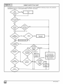
CHIMNEY INSPECTION CHART
Foradditionalrequirementsrefertothe NationalFuelGasCodeNFPA541ANSIZ223.1-2002andANSIINFPA211-2003Chimneys,Fireplaces,Vents,andSolidFuel
Burnin9 Appliancesin the U.S.A. or to the CanadianInstallationCodeCSA B149.1-05 in Canada.
I
Rebuild
Reline
andtile debris?
Removemortar
1_
.._
Yes
tile m.isalignment,
mg sections,
_10
No
Oondonsoto
Not Suitable
adapter venting
ins[ruc_lons Tor
/,%-\
opp,cotion
/
w
",,<u,ob,,y
of chimney?
sll
/
w,.
belowroofline?
!
_
_
_
Yes
"_
_]
I
j Tu_
I
Is Chimney to
h_ a_i_t_H
t,-,=
"_fur'na;e_
\
No
_,,,_..
_'_
t,l_.[.
Ir
_
/
V
_
adapter
I
1
Line chimney
stz
per
NSCNGPIC
Not Suitable
_
I .,.,.,/"
with properly
liner or Type-g vent per NFGC or
mstructlons.
_
I
ed,,stedfle,ib,o eta,
T
Install chimney
[
V
Chimney
exposed to outdoors
•
i
PartCofchimney
adapter venting
instructions for
Vent Sizing Tables
andlineror ventmanufacturer's
_le
|
-,,<u,,ab,,y
V
_ ia_;PutcetloPnesr
'
441 01 261302
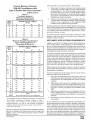
If the inspection
Exterior
Masonry
Chimney,
FAN+NAT
Installations
with
Type-B
Vent Connectors
© NFPA & AGA
Table ACombined Appliance
Maximum Input Rating in
Thousands of Btu per Hr
INTERNAL
12
19
28
38
6
74
119
178
257
8
80
130
193
279
10
84
138
207
299
15
NR
152
233
334
20
NR
NR
250
368
30
NR
NR
NR
404
INTERNAL
(FT)
12
a UL listed (ULC listed in Canada)
vent. Relining with a listed metal
ered to be a vent-in-a-chase.
If a metal liner or Type-B
19
0
APPLIANCE
APPLICATION
space
no other
between
the
REQUIREMENTS
Appliance
operation
has a significant
impact on the performance
of the venting system.
If the appliances
are sized, installed, adjusted, and operated properly, the venting system and/or the appliances should not suffer from condensation
and corrosion.
The
venting system and all appliances
shall be installed in accordance
with applicable
listings, standards,
and codes.
38
Temperature:
17 to 26 ° F*
99
141
The furnace
heating load requirement
plus any margin that occurs because of
furnace model size capacity increments.
Heating load estimates
can be made using approved
methods available
from Air Condi-
[o
8
52
74
111
154
o
10
NR
90
125
169
is
NR
NR
167
212
2O
NR
NR
212
258
30
NR
NR
NR
362
Temperature:
121
5 to 16° F *
166
'-
vent is used to line a chimney,
28
55
Local 99% Winter Design
NR
78
metal liner or UL listed Type-B
liner or Type-B vent is consid-
appliance
shall be vented into the annular
chimney and the metal liner.
AREA OF CHIMNEY
(SQ IN.)
Local 99% Winter Design
6
6
Indicates the chimney exceeds the maximum
permissible
size in the tables, the chimney should be rebuilt or relined to
conform
to the requirements
of the equipment
being
installed and the authority having jurisdiction.
A chimney without a clay tile liner, which is otherwise
in good condition, shall be rebuilt to conform to ANSI/N FPA 211 or be lined with
Table BMinimum Allowable Input Rating of
Space-Heating
Appliance in
Thousands of Btu per Hr
VENT
HEIGHT
chimney:
b.
AREA OF CHIMNEY
(SQ IN,)
(FT)
used tile-lined
Shows signs of vent gas condensation,
the chimney should
be relined in accordance
with local codes and the authority
having jurisdiction.
The chimney should be relined with a
listed metal liner, Type-B vent, or a listed chimney adapter
kit to reduce condensation.
If a condensate
drain is required
by local code, refer to the NFGC, Section 10.9 for additional
information
on condensate
drains.
Double-Wall
VENT
HEIGHT
of a previously
a.
should
be sized to provide
100 percent
of the design
tioning Contractors
of America
(Manual J); American
Society of
Heating, Refrigerating,
and Air-Conditioning
Engineers;
or other
approved
engineering
methods.
Excessive
oversizing
of the furnace could
cause
the furnace
and/or
vent to fail prematurely.
When a metal vent or metal liner is used, the vent or liner must be in
good condition
manufacturer's
and be installed
instructions.
in accordance
with the vent or liner
8
NR
94
135
182
10
NR
111
149
198
15
2O
NR
NR
193
247
To prevent
NR
NR
NR
293
lowing
30
NR
NR
NR
377
1.
The return-air
temperature
must be at least 60°F db except
for brief periods of time during warm-up
from setback at no
lower than 55°F db or during initial start-up from a standby
condition.
2.
Adjust the gas input rate per the
Low gas input rate causes low vent
ing condensation
and corrosion
in
ing system.
Derating
is permitted
2000'1
3.
Adjust the air temperature
rise to the midpoint of the rise
range or slightly above. Low air temperature
rise ca n ca use
low vent gas temperature
and potential
for condensation
problems.
4.
Set the thermostat
short cycling.
0
Temperature:
-10 to 4° F*
6
Local 99% Winter Design
NR
NR
145
196
8
NR
NR
159
213
o
10
NR
NR
175
231
_
is
NR
NR
NR
283
20
NR
NR
NR
333
30
NR
NR
NR
i
-11 ° F
or
lower
Local
99%
Winter
Not recommended
* The 99% Winter Design Dry-Bulb
1993 ASHRAE
(United States)
-11 ° F or
configuration
(db) temperatures
are found in the
Fundamentals
Handbook, Chapter 24, Table I
and 2 (Canada), or use the 99.6% heating db
Refer
to the Chimney
in_._..pectio
n.
441 01 2613 02
Inspection
the fol-
installation
instructions.
gas temperatures,
ca usthe furnace and/or ventonly for altitudes
above
Chart
to perform
heat anticipator
or cycle
rate to reduce
such as detergent,
paint, glue, aerosol spray, bleach, cleaning solvent, salt, and air freshener,
and can cause corrosion
of furnaces
Inspections
before the sale and at the time of installation
will determine the acceptability
of the chimney or the need for repair and/or
chimney
and vent system,
Air for combustion
must not be contaminated
by halogen compounds which include chlorides, fluorides,
bromides, and iodides.
These compounds
are found in many common
home products
temperaturesfound
in the 1997 or 2001 ASHRAE Fundamentals
Handbook, Climatic Design Information chapter, Table 1A (United
States) and 2A (Canada).
(re)lining.
in the furnace
must be observed:
NR
Design
Temperature:
lower*
for any vent
condensation
precautions
and vents.
a
Avoid
using such products
ply. Furnace use during construction
the furnace to be exposed to halogen
ture failure
of the furnace
in the combustion-air
sup-
of the building could cause
compounds,
causing prema-
or ventincj_stem
due to corrosion.
Ventdampers
onanyappliance
connected
to the
common
vent
can cause condensation
and corrosion in the venting system.
Do
not use vent dampers on appliances
common vented with this furnace.
8. Gas Supply
and Piping
Gas Piping Requirements
CARBON MONOXIDE
EXPLOSION HAZARD.
Failure to follow
result in serious
damage.
POISONING,
FIRE
AND
NOTE: The gas supply line must be installed by a qualifted
technician
in accordance
with all building codes.
NOTE:
safety warnings
exactly could
injury, death, and/or property
Models designated for Natural Gas are to be used
with Natural Gas ONLY, unless properly converted to
use with LP gas.
Gas Supply Requirements
•
Use only the Type of gas approved
plate for approved
•
for this furnace.
b.
When flexible connectors
are used, the maximum
shall not exceed 36" (915 mm).
c.
When
valves
d.
The use ofcopper
lever handle
type manual
equipment
are used, they shall be T-handle
valves.
Natural
7"
14"
4.5"
11"
14"
11"
shutoff
FIRE HAZARD
Supply Pressure
Propa ne
length
tubing for gas piping is NOT approved.
Failure to follow safety warnings
result in death or personal injury.
Min,
by a li-
It is recommended
that a manual equipment
shutoff valve be
installed in the gas supply line outside the furnace.
Locate
valve as close to the furnace as possible where it is readily accessible.
Refer to Figure 12.
I Gas Pressures
Max.
be performed
2.
Do not allow minimum supply pressure to vary downward.
Doing so will decrease
input to furnace. Refer to Table 3 for gas
supply. Refer to Table 6 and Table 7 for manifold pressures.
Recommended
Gas supply connections
MUST
censed plumber or gas fitter).
Install gas piping in accordance
with local codes, or in the absence of local codes, the applicable
national codes.
Gas input must not exceed the rated input shown on the rating
plate. Overfiring
will result in failure of heat exchanger
and
cause dangerous
operation.
Gas Type
of Massachusetts.
a.
1.
See rating
gas type.
In the state
service
exactly
could
Use wrench to hold furnace gas control valve when
turning elbows and gas line to prevent damage to
the gas control valve and furnace.
Typical Gas Piping (N8MP)
Manual shut- off
Drip Leg and Union, Union* should be outside the
cabinet. Manual shut- off valve MUST be upstream of
dripleg, union, and furnace.
valve
Alterative
Use elbows and 3" pipenipple to connectvalveto
piping when using right side gas pipeentry. _.
LP Low pressure
switch.
3'_pipe
25-24-86
* Union
3.
_]
may be installed
inside
the cabinet
Useblackironorsteelpipeandfittingsorotherpipeapproved
by local code.
when
necessary
because
4.
of clearances.
Use pipe thread
LP gases.
compound
which
is resistant
to natural
and
441 01 261302
Use ground joint unions and install a drip leg no less than 3"
long to trap dirt and moisture before it can enter gas control
valve inside furnace.
5,
6,
Provide a 1/8" NPT plugged tapping for test gauge connection
immediately up stream of gas supply connection to furnace.
7.
Use two pipe wrenches when making connections
furnace gas control valve from turning.
Gas Valve with Elbows
(N8MP)
to prevent
NOTE: If local codes allow the use of a flexible gas appliance connector, always use a new listed connector.
Do not use a connector
which
has previously
served
another
gas appliance.
8.
Flexible corrugated
metal gas connector
may NOT be used
inside the furnace or be secured or supported
by the furnace
or ductwork.
9.
Properly size gas pipe to handle combined appliance load or
run gas pipe directly from gas meter or LP gas regulator.
3.
Turn assembly
an additional
3/8 turn to position
inlet near the
bottom back corner of the gas valve in line with gas opening
on left side of furnace,
see Figure 15.
10. Install correct pipe size for run length and furnace rating.
4.
Gas supply line then can be run directly
11. Measure pipe length from gas meter or LP second stage regulator to determine gas pipe size.
Piping with Close Nipples and Standard Elbows
1.
Assemble
in Figure
2.
Follow
Right Side Gas Supply Piping (N8MP)
elbows
13.
steps
and nipples
2 through
Gas line can be installed directly to the gas valve through the hole
provided in the right side of the cabinet. See Figure 12
similar
4 Piping
into opening
of elbow.
to street
elbows
Street
Elbows.
with
Gas Valve with Elbows
shown
(N8MP)
Left Side Gas Supply Piping (N8MP)
Two(2)
two(2)
Figure
90 ° street
close
12.
nipples
elbows
or two(2)
are required
90 ° standard
for left side
elbows
and
gas supply.
See
Piping with Street Elbows
1,
Assemble
the elbows
so that the outlet of one(l)
elbow
is 90 °
from the inlet of the other. The elbows should be tight enough
to be leak proof. An additional
1/4 turn will be required at the
end of step 2, see Figure 13.
25-24-96a-2
iiiiiiiiiiiiiiiiiiiiiiiiiiiii_;!iiiiiiiiiiiiiiiiiiii!!iiiiii!!il;iiiiii!i
¸iiiii!!iiiiiiiiiiiiiiiiiiiiiiiiiiiiiiiiiiiiiii;i;ii;!iiiiiiiiiii_i
FIRE HAZARD
Failure
to follow
result
in death,
damage.
safety
personal
warnings
injury
exactly
could
and/or
property
Use wrench
to hold furnace
gas control
turning
elbows
and gas line to prevent
the gas control
valve and furnace.
(_
2,
Left Side Gas Entry C8MP) (See Figure 16)
25-23-23c
Screw elbow assembly into gas valve far enough to be leak
proof. Position el bow assembly so that the inlet of the el bow is
at the top of the gas valve. An additional
3/8 turn will be required in step 3. Turn open end of inlet elbow
side of the furnace (1/4 turn), see Figure 14.
441 01 2613 02
valve when
damage
to
to face the left
Pipe can be run directly to gas valve through
the left side of the cabinet.
the hole provided
in
Right Side Gas Entry C8MP) (See Figure 16)
Two (2) 90 ° street
(2) close
nipples
elbows
or two (2) 90 ° standard
are required
elbows
and two
for right side gas supply,.
[_
2.
Follow steps 2 through 4 Piping
with Street Elbows.
Typical Gas Piping ('aMP)
FIRE OR EXPLOSION HAZARD.
Failure to properly
result
in death,
damage.
install metal gas connector
could
personal
injury
and/or
property
A flexible
corrugated
metal gas connector
must be
properly
installed,
shall not extend through
the side
of the furnace,
and shall not be used inside
the
furnace.
Black iron pipe shall be installed at the furnace gas
control valve and extend a minimum of 2" outside
furnace.
25-25-02
Additional LP Piping Requirements
Piping with Street Elbows
1.
2.
Screw one elbow
from the furnace.
onto gas valve with the outlet facing
•
Have a licensed LP gas dealer make all connections
at storage tank and check all connections
from tank to furnace.
•
If copper tubing is used, it MUST comply with limitation set in
Local Codes, or in the absence of local codes, the gas codes
of the country having jurisdiction.
•
Two-stage
away
Screw second elbow onto first elbow tight enough to be leak
proof. An additional
1/4 turn will be required at the end of step
2. See Figure
17 and Figure
Gas
Valve
18.
with
Elbows
regulation of LP gas is recommended.
('8MP)
FIRE OR EXPLOSION HAZARD.
An open flame or spark could result
personal injury and/or property damage.
in death,
Liquefied petroleum (LP) gas is heavier than air and
will settle and remain in low areas and open
depressions.
Thoroughly
ventilate area and dissipate gas. Do
NOT use a match or open flame to test for leaks, or
attempt to start up furnace
before thoroughly
ventilating area.
25-25-03
iiiiiiiiiiiiiiiiiiiiiiii
i:iiiiiiiiiii::::::;iiiiiiii!;!!i!!!!!i!!!!!!i!iiiiiiiiiiiiiill
I
Gas
Valve
with
Elbows
Final Check
(_8MP)
•
Test all pipe for leaks.
•
If orifices were changed,
leaks.
During
pressure
testing
make sure they are checked for
of gas supply
piping
system:
a. If test pressure
does not exceed
1/2" psi, isolate the
furnace
from the gas supply piping system
by closing the
equipment
shutoff valve.
b. If test pressure exceeds 1/2" psi, the furnace
equipment
shutoff valve must be disconnected
supply piping system.
3.
Gas supply line then can be run directly
into opening
To check for leaks apply soap suds or a liquid
each joint. Bubbles forming indicate a leak.
of elbow.
_]
Assemble
elbows
in Figure
13.
and nipples
similar
to street
elbows
detergent
to
Do not use an open flame to test for gas leaks. Fire or explosion could occur.
Piping with Close Nipples and Standard Elbows
1.
and its manual
from the gas
shown
•
Correct
even the smallest
leak at once.
441 01 2613 02
9. Electrical
Wiring
*8MPN/L Models
ELECTRICALSHOCK
The J-box is installed in the burner
casing.
An alternate
J-box location
HAZARD.
Failure to follow safety warnings
result in death or personal injury.
exactly
could
Turn OFF electrical power at fuse box or service
panel before making any electrical connections
and ensure a proper ground connection
is made
before connecting line voltage.
The furnace MUST be electrically
wired and grounded
in accordance with local codes, or in the absence of local codes, with the
National Electrical
Code (NEC), ANSI/NFPA
70-2002
in the U.S.,
The power
Electrical
supply
Code
(CEC),
to the furnace
104 VAC and 127 VAC during
performance.
CSA C22.1
connections
furnace
must
operation
in Canada.
be between
for acceptable
Field wiring connections
must be made inside the furnace connection box. A suitable strain relief should be used at the point the
wires exit the furnace
Remove
and save two screws
2.
Move large
3.
Clip wire tie holding
4.
Move J-box to alternate location
removed from left side location.
holding
J-box
hole plug from right to left J-box
J-box
on left side of
can be used:
to casing.
location.
wires.
and attach using two screws
Position all wires away from hot surfaces,
sharp
moving parts. Do not pinch J-box wires or other
reinstalling
burner compartment
door.
Power Supply Wiring
or the Canadian
1.
compartment
on right side
casing.
Thermostat
Thermostat
location has an important effect on the operation of the
furnace.
Follow instructions
included with thermostat
for correct
mounting
electrical components
plus the amps for all installed accessories
(1.0 amps total for EAC and HUM). Ampacity can be determined
by using the NEC or CEC.
NOTE: Furnace will not have normal operation if line polarity is reversed. Check ALL field and control connections prior to operation.
Furnace must be installed so the electrical components
are protected from water and connected
to its own separate
circuit.
J- Box Relocation
and wiring.
Low voltage connections to furnace must be made on terminal
board to furnace control. (See Figure 19)
If cooling is used, the Y from the thermostat
must be connected
the control board Y to energize cooling blower speed.
Set thermostat
Support
Copper
conductors
shall be used. Line voltage wires should
conform to temperature
limitation of 63 ° F (35 ° C) rise. Wire and
circuit breaker sizing shall be based on the ampacity of the furnace
edges, and
wires when
heat anticipator
in accordance
with the
to
Technical
Manual.
Heat anticipator
fier is installed.
setting will need to be measured
if 24VAC humidiMeasure currentin
series from R to W at thether-
mostat.
Be sure 24VAC humidifier
is wired up to control.
Allow
furnace to operate for 2 minutes before recording
the AC amperage reading.
Set anticipator
on thermostat
to recorded value.
Optional Equipment
All wiring from furnace to optional equipment
MUST conform to local codes or, in the absence of local codes, the applicable national
codes. Install wiring in accordance
with manufacturer's
instructions.
Humidifier/Electronic
Air Cleaner
The furnace is wired for 115 VAC humidifier and/or electronic air
cleaner connection.
N8MPN/L Models
The J-box is installed in blower compartment
on left side of casing.
An alternate
J-box location on right side can be used.
REDUCED FURNACE LIFEHAZARD
1.
Remove bag containing
two hole plugs and two self-tapping
screws from loose parts bag in blower compartment.
Failure to follow
reduced
furnace
2.
Remove
3.
Move large
Do NOT exceed
115V/1.0
load for both
the EAC
terminal
combined.
4.
Move J-box to alternate
location and attach
tapping screws from bag.
5.
Apply two hole plugs from bag at left J-box location.
HUMIDIFIER - The 24VAC HUM is energized when the pressure switch closes on a call for heat. The HUM (115VAC) is energized when the inducer is energized.
6.
Position all wires away from sharp edges and moving parts.
Do not pinch J-box wires or other wires when reinstalling
blower compartment
door.
ELECTRONIC AIR CLEANER - EAC is energized when there
is a blower speed call, except is NOT energized when blower
operates in the hard-wired continuous fan mode.
441 01 261302
and discard
two screws
hole plug from
holding
J-box
right to left J-box
to casing.
location.
using
two self-
caution
life.
instructions
may result
in
amp. maximum
current
terminal
and the HUM
[_
Electrical
Furnace Control Fuse
Connections
The 24V circuit contains a 5-amp, automotive-type
on furnace control. (See Figure 20) Any electrical
fuse located
shorts of 24V
wiring during installation,
service, or maintenance
may cause fuse
to blow. If fuse replacement
is required, use only a fuse of identical
size (5 amp.).
Control
115V.60Hz.
Connections
Gr_nd
24v c4.
Jumper _>_/___
Thermostat
I
L
!
]
,
I
_
_
_
_
DiagnosticLight
.0M
Low Voltage
Terminal Board
"_ _
_
25-24-98
NOTE: 115 VAC/6OHz/single-phase
Operating voltage range*: 127 VAC max, 104 VAC min.
* Permissible
limits
of voltage
at which
unit will operate
satisfactorily
Furnace Control
The furnace control is preset at the factory with ON delay of 30 seconds in the heating mode. The blower OFF timing is preset at 140
seconds.
If desired, the fan OFF delay can be reset to obtain the
longest delay times while still maintaining
comfort levels.
See
"Furnace Wiring Diagram".
10.
Ductwork
and Filter
(Upflow/Horizontal)
Cutting
Side Return Air Opening
CARBON MONOXIDE POISONING HAZARD.
Failure to properly
personal
injury.
seal duct could
result
Do NOT draw return air from inside
room where
furnace
is located.
MUST
be sealed
to furnace
in death or
a closet
Return
or utility
air duct
casing.
Plugged
,,Starting
Duct Connections
0
/_/'I'I
/
Hole
I
This furnace may be installed in only a bottom or side return-air
duct application.
Return air duct connections
through the back of
the furnace is NOT permitted.
Upflow
cutting
ONLY: Side return-air
duct connections
out the embossed
area shown in Figure
can be made by
21. A plugged
hole is provided at each furnace side duct location to help start cutting the opening.
Side duct connections
are NOT permitted in horizontal flow applications.
Upflow
and
Horizontal
Flow:
Bottom
return-air
duct
connec-
tions can be made by removing the knockout
panel in the furnace
base. Do NOT remove knock-out
except for a bottom return-air
duct connection.
Duct Design
Design and install air distribution
system to comply with Air Conditioning Contractors
of America manuals or other approved
methods that conform to local codes and good trade practices.
When the furnace is located in an area near or adjacent to the living
area, the system should be carefully designed with returns to minimize noise transmission
through the return air grille. Any blower
moving a high volume of air will produce audible noise, which could
be objectionable
when the furnace is located very close to a living
_]
441 01 2613 02
area.
It is often
advisable
floor or through
the attic,
to route
the return
air ducts
under
the
Filters are not supplied
•
Refer to furnace Technical
for air flow information.
•
Size ductwork to handle air flow for heating (and air conditioning if so equipped).
Support
Manual
(Blower
Data)
See Table
but can be purchased
4 for required
high-velocity
filter sizes.
iiiiiiiiiiiiiiiiiil
_i!!!!:_i;:ii;i;i;i;i;i;i;_;:_:_:_:_i_iiiiiiiiiiiiiiiiiiiii_i_!!i
¸!I
¸iiiiiiiiiiiii!iiiiiiiiiii
High-Velocity
Cabinet
Duct Installation Requirements
When a furnace is installed so that supply ducts carry air circulated by the furnace to areas outside of the space containing the furnace, the return air shall also be handled by duct(s)
sealed to the furnace
casing and terminating
outside the
space containing
the furnace.
Internal
Air Filter Sizes (max.600FPM)
Filter
External
Filter Rack
Width
Bottom
Bottom
Side+
151/2
14X25
14X25
14X25 or 16X25
191/2
16X25"
16X25"
16X25"
223/4
20X25"
20X25"
16X25"
Greater than 1600 CFM requires both (left and right) side return filter
racks in upflow position.
+ Side return air duct(s) is not permitted with horizontal or downflow furnace
installation,
CARBON MONOXIDE POISONING HAZARD.
Use either
Failure to follow safety warning exactly could
result in death, personal injury, and/or component
damage.
filter type:
•
Washable,
flow rating
filters are based on a maximum
air
•
Disposable,
low velocity filters are based on a maximum
flow of 300 FPM when used with external filter grille.
air
Install cooling coil on furnace discharge. Cool air
passing over heat exchanger could cause condensate to form resulting in heat exchanger failure.
•
with these furnaces,
from your distributor.
high-velocity
of 600 FPM.
When the furnace is used with a cooling unit, the furnace shall
be installed parallel with or on the upstream side of the cooling
unit to avoid condensation
in the heating element.
RISK OF REDUCED FURNACE LIFE
With a parallel flow arrangement,
the da topers or other means
used to control flow of air shall be adequate
to prevent chilled
air from entering the furnace. Chilled air going through the furnace could cause condensation
and shorten
furnace
life.
Use of excessively dirty and/or restrictive air filters
may increase furnace operating temperatures
and
shorten the life of the furnace.
Dampers
(purchased
locally)
can be either automatic
or
manual. Manually or automatically
operated dampers MUST
be equipped
with a means to prevent furnace and air conditioning operation, unless damper is in the full heat or cool position.
Filters specified for the furnace are rated at a maximum
of 600 FPM air velocity and sized for the furnace's
airflow rate. Replacement filters must be of equivalent
type, size, and rating except as described below.
•
Installation of locking-type
dampers
is recommended
in all
branches, or in individual ducts to balance system's air flows.
•
Non-combustible,
flexible duct connectors are recommended for return and supply connections to furnace.
•
If air return grille is located close to the fan inlet, install at least
one 90 ° air turn between fan and inlet grille to reduce noise.
•
Ductwork installed in attic or exposed
requires a minimum of 2" of insulation
barrier.
•
Ductwork installed in an indoor unconditioned
space requires
a minimum
of 1" of insulation with indoor type vapor barrier.
Failure to follow
these Caution may
premature furnace component failure.
•
The furnaces with 1600 or less CFM rating use a 16" x 25"
high-velocity
filter.
On these models the filter may be
mounted internally for bottom return or a filter and rack may
be mounted externally
for bottom return.
•
The furnaces with greater than 1600 CFM require that both
(left and right) side returns are used. Two side return filters
and racks are required. Filter racks must be mounted externally. See Figure 24.
•
If return air must be on one side only, an optional 20" x 25"
filter standoff rack kit can be used. (See Figure 22.) For bottom return, a n internal filter can be used or a filter rack kit can
Inspection Panel on some models
that the heat exchanger
ca n be viewed
be mounted
for possible
light assistance
or a probe can be inserted
stream. This access cover shall be attached
to prevent
openings
using
for sampling
the air
in such a manner as
in
Disposable, low-velocity filters may be used to replace
washable, high-velocity filters, providing they are sized
for 300 FPM or less.
to outside temperatures
with outdoor type vapor
For a furnace not equipped with a cooling coil, the outlet duct shall
be provided with a removable access panel. This opening shall be
accessible when the furnace is installed and shall be of such a size
result
I
•
externally.
See pages 40 & 46, CirculatorAirBIowerData
data.
for additional
NOTE: The 20" x 25" standoff side filter rack gives more filter area
but does not provide more air. See Figure 22. To achieve 2000
CFM 2 side returns are still needed. See Figure 24.
air leaks.
NOTE:
Filters
A filter MUST be used.
441 01 2613 02
Disposable
low-velocity
filters
may
be replaced
with
washable, high-velocity
filters. Washable, high-velocity
filters can
be replaced ONLY with same type and size filter unless low-velocity filters
meet the minimum
size areas
for 300
FPM or less.
Internal Filter in Bottom- Return Installation
Optional
Duct Standoff
20 x 25 Optional
Filter Rack
When installing a bottom-mounted
filter inside the furnace, install
the filter clips on the edge of the bottom duct opening with the wider
end of the clips toward the blower, as shown in Figure 25. Clips
may be obtained
from your distributor
or fabricated
from sheet
metal (Figure
26). Insert filter into side clips first and push filter
back until it is fully engaged
into back clip.
Bottom
Mounted
Filter
Center Clip
sideto
25-23-05-4
Filter
Optional Filter Rack Installation: Side Return
25-24-18-1
Center the filter rack on the side panel, flush with the bottom edge
of the furnace.
Mark the fastening
holes. Drill the fastening
holes
in the side panel and fasten the filter rack in place with sheet metal
screws.
See Figure
23 and Figure
24.
iiiii i¸i¸¸i¸i¸iiiiiii_¸I¸!iii
!iii¸iiiiiiiiiiiii iiiiiiiiiiiiiiiiiiiii;ii;ii;ii;ii
¸ii
Side
Return
Filter
Rack
11/4"
26 Ga, Galvanized
Steel
NOTE: If filters are only suitable
for heating application,
advise
homeowner
that filter size may need to be increased
if air conditioning is added.
Filter
25-23-05-4a
When a refrigeration
coil is used in conjunction
with this furnace, it
must be installed on the discharge
side of the furnace to avoid condensation
in the heat exchanger.
The coil installation
instructions
iiiiiiiiiii ¸iiiiiiiiiiiiiiiiii!!ili;i!i!!!!!!!i!! i!iiiiiiiii;i
i_
Addition Of Air Conditioning
Filters
Installed
on
Two
Sides
must be consulted
for proper coil location and installation
procedures.
With a parallel
flow arrangement,
dampers
must be
installed to prevent chilled air from entering the furnace.
Ifmanually operated
dampers
are used, they must be equipped
with a
means to prevent operation
of either unit unless the damper is in
full heat or full cool position.
Using Two
Filter Racks
Copper
or plastic
tubing may be used for the condensate
drain line.
25-23-05-3
Filter
Filter
441 O1 261302
11. Ductwork
and Filter
(Downflow)
CARBON MONOXIDE POISONING HAZARD.
FIRE HAZARD.
Failure to properly seal duct could result in death
or personal injury.
Do NOT draw return air from inside a closet or
utility room where furnace is located. Return air
duct MUST be sealed to furnace casing.
Failure
to install
furnace
on noncombustible
subbase could result in death, personal injury and/or
property damage.
Place furnace
on noncombustible
subbase
on
downflow
applications,
unless
installing
on
non-combustible
flooring.
Outlet Duct Flange
FIRE HAZARD.
Downflow
installations
with cased coils require the furnace outlet
duct flange to be bent outward and flat to mate the outlet of the furnace to the cased coil.
Failure to connect
the return air duct to the top of a
downdlow
furnace
could
result
in death,
bodily
injury, and/or property
damage.
Side return air duct(s) may cause excessive
and/or air temperatures,
which could result
bodily injury, and/or property
damage.
Return air duct is to be connected
downflow
furnace.
to only
Sub-Bases
furnace
in death,
for Combustible
Floors - Furnace Only
Note: When using the subbase
for combustible
floors, the discharge air duct flanges on the furnace MUST be broken down to
provide proper fit up to the subbase.
Use duct pliers to bend the
duct flanges flat onto the furnace casing. DO NOT bend the duct
the top of
flanges inward (toward
tions may occur.
The
Subbase
the heat
for Combustible
exchangers)
Floors
downflow furnace is set on a combustible
nace is installed on a coil box.
BURN HAZARD.
The opening
SHIELD
NAHAOO2VC
as
be used
when
a
floor, even when the fur-
Cut the opening in the floor according
Table 5 because the base is equipped
center the base over the opening.
The vent may be hot. Failure to install vent shield
properly could result in personal injury.
Install
VENT PIPE
described below.
MUST
as air flow restric-
to the dimensions
in
with locating tabs that
in the base is 11/4" shorter
and
11/8" narrower
than the minimum
required size of the opening in the floor.
This is done to maintain a 1" clearance
between the floor and
the plenum.
2.
Fabricate
the plenum to the dimensions
given in Table
Note that the dimensions
given are outside dimensions.
3.
Set the base over the opening in the floor, centering the opening in the base over the opening in the floor. Fasten the base to
Vent Shield
Vent shield is required for all downflowinstallations.
exit out the side of the furnace for all downflow
The vent Must
installations.
This
the floor with screws
places the hot vent pipe (over 300 ° F) within reach of children. Vent
shield attaches to side of furnace to cover vent pipe. See Figure 5
in "2, Installation"section.
] Sub-bases
Sub-base
Combustible
Part Number
Floors
See Figure
27 and Figure
Dimensions
Opening
In Floor
Opening In
Base For Plenum
Typical Plenum
Dimensions
J*
K**
L
M
N
P
R
NAHHO01 SB
1511/16
283/4
149/16
18
181/4
145/8
15
131/2
15
131/2
NAHHOO2SB
195/16
283/4
183/16
18
181/4
181/4
15
171/8
15
171/8
NAHHOO3SB
2215/16
283/4
2113/16
16
161/4
21 _/8
15
193/4
15
193/4
NAHHOO4SB
1511/16
209/16
149/16
16
161/4
145/8
15
131/2
15
131/2
NAHHOOSSB
19s/16
209/16
183/16
16
181/4
181/4
15
171/8
15
171/8
193/4
15
193/4
Subbase
for Furnace
Only
for Coil Box
NAHHOO6SB
2215/16
Outside Dimension
Base
Spacer
441 01 261302
Side To Side
209/16
2113/16
16
28.
Drop the plenum through the opening in the base. The flange
of the plenum should rest on top of the combustible
floor base.
H"
Subbase
"*
for Combustible
Sub-base for Combustible
Floor Dimensions
for
Floors
or nails.
5.
161/4
211/8
15
Exploded View of Sub-Base
Furnace ONLY
for
Exploded
Downflow
View of Base for
Cased Coil
Combustible
Floor Base
I tr
Combustible
FloorBase
25-21-46b
iiiiiiiiiiiiiiiiiiii_i_}!
¸i!}!i}!;;i;iiii!
i;;i;i
lllliii;}i¸i
¸i¸i¸i¸
i¸ii;i;i
¸;}i;;i;;i;;i;;i;;i;l
iiiiii
¸iiiiiiiiiiiiiii
iilii}i
Setting
¸i!i i¸i
Setting
the
Base
Subbase
Insulation
'_
the
Base
/
II
Subbase Furnac_
Insulation
/
Wood Floor
Plenum
25-20-46A
_. %
_W_°°d
Fl°°r
Consideration
must be given to the height of the base to allow for
easy installation
of the condensate
drain. See Figure 31. This
Wood Screw
Sub-base for Combustible
subbase
for combustible
floors has been designed
so that the
height of the subbase raises the downflow
coil off the floor to allow
easy installation
of the condensate
drain
Floors - Downflow
Coil
Adapter Box
Condensate
Line Raised
by Base
The subbase for combustible
floors is required when a downflow
furnace,
used with a downflowcoilbox,
is set on combustible
flooring.
1,
Cut the opening in the floor according
Table 5 because the base is equipped
center the base over the opening.
to the dimensions
in
with locating tabs that
The opening in the base is 11/4 "shorter and 11/8 " narrower
than the minimum
required size of the opening in the floor.
This is done to maintain a 1" clearance
between the floor and
25-20-52
the plenum.
Non-Combustible
2.
3.
Fabricate
the plenum to the dimensions
given in Table
Note that the dimensions
given are outside dimensions.
Set the base over the opening in the floor, centering the opening in the base over the opening in the floor. Fasten the base
to the floor with screws
or nails.
See Figure 29 and
Figure 30.
Drop the plenum through the opening in the base.
of the plenum should rest on top of the combustible
Floor
5.
The flange
floor base.
Set the furnace over the opening in the floor. If necessary,
grout
around the base to seal air leaks between the base and the floor.
Duct Connections
In the downflow
position,
the return-air
duct must be connected
to
only the top of the furnace.
Top return connections
can be made by
removing the knockout
panel in the furnace base. Return air connection through the side(s) or back of the furnace is NOT allowed.
441 01 261302
Duct Design and Duct Installation Requirements
See Section
10.
Internal Filter in Top Return Installation
When instal ling top-mounted
filter inside the furnace,
install the fil-
ter clips on the edge of the top duct opening with the wider end of
the clips toward the blower as shown in Figure 32. Clips may be
obtained
from your distributor
or fabricated
from sheet metal
(Figure
33). Insert filterintosideclips
it is fully engaged
into back clip.
firstand
push filter backuntil
26 Ga. Galvanized
Top Mounted Internal Filter
Steel
j_
NOTE:
If filters
are only
suitable
vise homeowner
that filter
conditioning
is added.
application,
ad-
size may need to be increased
for heating
if air
Addition Of Air Conditioning
Clip
side-to-side
12. Checks
See Section
10.
and Adjustments
Startup
NOTE:
Manual.
Refer
to startup
procedures
in the
Users
FIRE OR EXPLOSION HAZARD.
Information
Failure to turn OFF gas at shut off before connecting
manometer
could result
in death, personal
injury
and/or property
damage.
Turn
OFF
manometer.
ELECTRICAL
HAZARD.
SHOCK,
FIRE,
OR
EXPLOSION
1.
Failure to follow safety warnings
exactly could
result in death, personal injury and/or property
damage.
gas
at
shut
before
connecting
With gas OFF, connect manometer
to manifold pressure
tap
on outlet of gas control valve. See Figure 34. Use a manometer with a 0" to 12" water column range.
Typical
If any sparks, odors or unusual noises occur,
immediately
shut OFF gas and power to furnace.
Check for wiring errors or obstruction to blower.
off
RegulatorAdjustment
Under Ca
Gas
Control
Valve
Honeywell
HONEYWELL
Outlet
Pressure
©o
Tap
1/8NPT
/
Gas Supply Pressure
Gas supply
pressure
ues listed on rating
ers.
should
be within
plate. Pressures
minimum
are usually
and maximum
OUTLET
val-
set by gas suppli-
Inlet
Pressure
Tap 1/8NPT
(See LP Gas Conversion Kit instruction manual for furnaces converted to LP gas.)
Manifold Gas Pressure Adjustment
NOTE:
atin
Make adjustment
.
441 01 261302
to manifold
pressure
with burners
oper-
25-24-98a
2.
Turn gas ON. Operate
the R to W thermostat
3.
Remove
nace
manifold
as control
the furnace
connection
pressure
valve.
by using a jumper
on the control.
adjustment
Turn ad_screw
screw
cover
wire on
on fur-
counterclock-
wiseto decrease
manifoldpressureand clockwise
to
increase
NOTE: Adjustment screw cover MUST be replaced on gas control
valve before reading manifold pressure and operating furnace.
Set manifold
4,
5.
pressure
to value
shown
in Table
6 or Table
When the manifold
pressure is properly set, replace
justment
screw cover on the gas control valve.
the ad-
board. Remove manometer
connection
from manifold
presRemove jumper
wire from thermostat
connection
on fan
sure tap, and replace plug in gas valve.
7.
Check for leaks at plug.
Natural Gas Input Rating Check
The gas meter
can be used to measure
with gas supplier
for actual
Check
BTU content.
Turn OFF gas supply to all appliances
other than furnace
start furnace.
Use jumper wire on R to W.
2.
Time how many seconds it takes the smallest
meter to make one complete
revolution.
uses a 2 cubic foot dial, divide results
and
dial on the gas
(seconds)
by
per cubic foot
1,000
Time Per Cubic
Foot in
3,600
Failure to follow
these
result in death, personal
age.
instructions
injury and/or
exactly
could
property
dam-
This high-altitude
gas-conversion
shall be done by
a qualified
service
agency
in accordance
with the
Manufacturer's
instructions
and
all applicable
codes and requirements,
or in the absence
of local
codes, the applicable
national
codes.
furnace
may be used at full input rating when installed
in the USA. In Canada, the input rating must be derated 5% (natural) or 10% (LP) for each 1000' above sea level. This may be accomplished
by a simple adjustment
of manifold
pressure
or an
orifice change, or a combination
of a pressure adjustment
and an
the proper furnace
manifold
pressure
and gas orifice size to
achieve proper performance
based on elevation
above sea level
for both natural gas and propane gas.
To use the natural gas table, first consult your local gas utility for
the heating value of the gas supply. Select the heating value in the
Seconds
48
section
of the altitude
75,000
Nameplate
3.
Remove jumper wire from R to W.
4.
Relight all appliances and ensure all pilots are operating.
and heating
value
provides
not only
High Altitude
Input Rate =
Sea Level Input Rate x (Multiplier)
Elevation
High
Natural
Altitude
Gas
[USA]
Multiplier
LP Gas
2001'-3000'
0.95
0.90
Orifice Sizing
3001'-4000'
0.93
0.86
NOTE:
4001'-5000'
0.91
0.82
5001'-6000'
0.89
0.78
6001'-7000'
0.87
0.74
7001'-8000'
0.85
0.70
the furnace
sized orifices
Technical
Support
for natural
and LP gas are listed
in
Manual.
Ensure furnace is equipped with the correct main burner orifices.
Refer to Table 6 or Table 7 for correct orifice size and manifold
pressure for a given heating value and specific gravity for natural
and propane gas.
_]
the
manifold pressure but also the orifice size. In the natural gas tables
the factoy-shipped
orifice size is in bold (42). Other sizes must be
obtained from service parts.
BTU Per
Hour
1,000 x 3,600 + 48 = 75,000 BTUH
Factory
at al-
titudes up to 2000'. When installed above 2000', the input must be
decreased
2% (natural) or 4% (LP) for each 1000' above sea level
first column and follow across the table until the appropriate
elevation for the installation
is reached. The value in the box at the inter-
Example
No. of Seconds
Per Hour
MONOXIDE
orifice change. The changes
required depend on the installation
altitude and the heating value of the fuel. Table 6 & Table 7 show
Refer to Example. The Example is based on a natural gas BTU
content of 1,000 BTU's per cubic foot.
Natural Gas
BTU Content
CARBON
These
input to furnace.
1.
If meter
FIRE,
EXPLOSION,
POISONING HAZARD.
7.
6.
Note:
two.
Operation Above 2000' Altitude
pressure.
* Based
on mid-range
of elevation.
441 01 261302
MANIFOLDPRESSUREAND ORIFICE SIZE FOR HIGHALTITUDEAPPLICATIONS
NATURAL GAS MANIFOLD PRESSURE (" w.c.)
..............................................................
MEAN ELEVATION
FEET ABOVE
SEA LEVEL
HEATING
0 to
2001 to
3001 to
4001 to
5001 to
6001 to
VALUE
2000
3000
4000
5000
6000
7000
at ALTITUDE
BTU/CU. FT.
Orifice
No.
Manifold
Pressure
Orifice
No.
Manifold
Pressure
Orifice
No.
Manifold
Pressure
Orifice
No.
Manifold
Pressure
Orifice
No.
Manifold
Pressure
7001 to
8000
Orifice
No.
Manifold
Pressure
41
3.7
725
41
3.7
41
3.4
750
41
3.5
42
3.6
700
775
800
Orifice
No.
Manifold
Pressure
41
3.6
42
3,6
42
3.3
41
3.6
42
3.7
42
3.4
42
3.1
825
41
3.7
41
3.4
42
3,5
42
3,2
42
2.9
850
41
3.5
42
3.6
42
3.3
42
3.0
42
2.8
875
41
3.6
42
3,6
42
3.4
42
3,1
42
2,8
42
2.6
900
42
3,7
42
3,4
42
3.2
42
2,9
42
2,7
42
2.5
925
41
3.7
42
3.5
42
3.3
42
3.0
42
2,8
42
2.5
44
3.3
950
41
3.5
42
3,3
42
3,1
42
2.9
42
2,6
42
2,4
44
3.1
975
42
3.7
42
3.2
42
2.9
42
2.7
42
2.5
44
3.2
45
3.6
1000
42
3.5
42
3,0
42
2,8
42
2.6
42
2.4
45
3.7
45
3.4
1050
42
3.2
42
2.7
42
2.5
44
3.3
45
3.6
43
3.6
42
2,5
44
3.2
45
3.6
1100
NOTE: Natural
gas data is based on 0.60 specific gravity.
Z223.1-2002/NFPA
54-2002
For fuels with different
_i_i_i_i_i_i_i_;_;%;
iiiiiiiiiiiiiiiiiiiiiiiiii_i;!_ii_i
iiiiiiiiiiiiiiiiiil;_i_;i;i;i;i;i;i;i;i
iiiiiiiiiiiiiiiiiiiiiiii¸¸;_;_¸i¸_;¸;¸;¸;¸;¸;¸;¸;¸;¸;¸;¸;¸;
iiiiiiiiiiiiiiiiii!_i_i_i!ii!iiiililililiiii!ii!
iiiiiiiiiiiiiiiiiiiiiiiiiiii!_i_i_i!ii!ii
specific gravity
or National Standard of Canada, Natural Gas And Propane Installation
consult the National
Fuel Gas Code ANSI
Code CSA B149.1-05.
i iiiiiiiiiiiiiiiiiiiiiiiiiiiiiiiiiiiiiiiiiiiiiiiiiiiiiiiiiiiiiiiiiiiiiiiii
i !ii i i("i!w.c.)
i! i! i! i! i! i! i! i! i! i! i! i! i! i! i! i! i!
LPG or PROPANE
GAS MANIFOLD i iPRESSURE
HEATING VALUE
MEAN ELEVATION
FEET ABOVE SEA LEVEL
at ALTITUDE
BTU/CU. FT.
0 to
2001 to
3001 to
4001 to
5001 to
6001 to
7001 to
2000
3000
4000
5000
6000
7000
8000
2500
10.0
10.0
9.0
10.0
9.4
8.5
10.0
Orifice Size
#54
#54
#54
#55
#55
#55
#56
NOTE: Propane data is based on 1.53 specific gravity. For fuels with different specific gravity consult the National Fuel Gas Code ANSI Z223.1-2002/N
54-2002
NOTE:
FPA
or National Standard Of Canada, Natural Gas And Propane Installation Code CSA B149.1-05.
The derating
In Canada,
of these
furnaces
at 2% (Natural
the input rating must be derated
5% (Natural
Gas) and 4% (Propane
Gas) has been tested
Gas) and 10% (Propane
Gas) for altitudes
and design-certified
by CSA.
of 2,000 to 4,500 above sea level. Use
the 2001 to 3000 column in Table 6 and Table 7.
The burner orifice part nos. are as follows:
Orifice #41
1096942
Orifice #42
Orifice #43
1011377
Orifice #44
Orifice #45
1011353
Orifice #54
Orifice #55
1011354
Orifice #56
High
Altitude
Air Pressure
_
; ;;;
_ ;;;;;;; ;;;;;;;;;;;;;;;;;;2
1011351
1011352
1011376
1011355
Manifold
Switch
The factory-installed
pressure switch need NOT be changed for
any furnace installations
from sea level up to and including 8,000'
altitude
Changing Orifices
1.
2.
3.
4.
After disconnecting
move the burner
compartment.
Disconnect
moved.
power and gas supply to the furnace, recompartment
door, exposing
the burner
gas line from
25-25-00
gas valve
so manifold
can be re-
Disconnect
wiring at gas valve. Be sure to note the proper
location of all electrical wiring before being disconnected.
Remove the four (4) screws holding the manifold
and gas
valve to the manifold
supports.
Do not discard any screws.
See Figure
441 01 261302
35.
Some Models may vary
5.
Carefully
6.
Remove the orifices from the manifold and replace
proper sized orifices. See Figure 36.
remove
the manifold
7.
Tighten
orifices
Figure 36.
8.
Reassemble
all parts in reverse order as removed.
Be sure to
engage the main burner orifices in the proper openings
in the
burners.
so they
are
assembly.
seated
and
them with
gas-tight.
[_
See
9.
After reassembling,
turn gas on and check all joints for gas
leaks using a soapy solution. All leaks must be repaired immediately.
Removing
NOx
inserts
Clearances
Measure from face of orifice
batck side of the manifold,
29.3
+_11"5mm
to the
"\k,,..k--..,.,.r_
j
25-40-03
LP Conversion
I
the furnace rating plate for the LP conversion
accessory
kit part
An
accessory
kit shall be used to convert to propane gas use, see
number.
CARBON
Failure
death,
injury.
MONOXIDE
to follow
property
POISONING
HAZARD.
this warning
can result
in
damage
and/or
personal
NOx inserts for use with Natural
Gas units
ONLY. If LP Gas is required,
NOx inserts must
be removed.
FIRE, EXPLOSION,
Failure
death,
injury.
to follow
property
UNIT DAMAGE
HAZARD.
this warning
can result
in
damage
and/or
personal
Main Burner Flame Check
Allow the furnace to run approximately 10 minutes. Then inspect
the main burner flames. See Figure 38.
Check
for the following:
•
Stable and blue flames. Dust may cause orange tips or
wisps of yellow, but flames MUST NOT have solid, yellow
tips.
•
Flames
extending
•
Flames
do NOT touch
directly
from burner
sides
into heat exchanger.
of heat exchanger
If any problems with main burner flames are noted, it may be necessary to adjust gas pressures
or check for drafts.
Main Burner
An LP conversion
accessory
kit is required
when operating
the furnace with LP gas.
*8MPLs
and N8MPLs
For LP conversion
discard insert.
Reinstall
NOTE:
screws.
screws.
It is very
contain
remove
screws
See Figure
important
NOx inserts.
that secure
the NOx insert and
10-10-78
37
to reinstall
the NOx
insert
mounting
NOTE: For Ignitor location see Figure 39.
441 01 261302
Ignitor
Changing Blower Speed
Location
ELECTRICAL
SHOCK HAZARD.
Failure to disconnect power could result in death,
personal injury and/or component damage.
Turn OFF power to furnace before changing
taps.
NOTE: Flame sensor has a different orientation
in all 050 models.
NOTE: The speed taps that the manufacturer
sets at the factory
for this furnace are based on a nominal 400 CFM per ton cooling
and the basic mid range on the temperature
rise for heating.
Since
the
manufacturer
If it is necessary
1.
REDUCED FURNACE LIFE HAZARD
to properly
in reduced
temperature
the blower
motor
speed taps
setting air temperature rise.
Use
ONLY
YES
for
Blower
set the air
furnace
life.
cannot
predict
the
static
rise
marked
may
to change
speeds,
refer to steps
below.
Refer to Furnace Wiring Diagram for location of the heating
and cooling speed taps located on the electronic
furnace control as well as location of unused blower motor speed leads.
Use the chart (Table 8 ) to determine
the blower motor speed
settings.
"Y" for
I
Wire
Motor Speed Taps for
NSMPNtL and *8MPN/L Model Sizes
Blower
Speed
Chart
Color
Speed
Motor
M LO
BLUE
M HI
ORN
HI
BLK
Black
High
LO
RED
Orange*
Med- High
050B12
N
Y
Y
N
Blue
075B12
N
Y
Y
Y
Red
075F16
N
N
Y
Y
100F14
N
N
Y
Y
100F20
N
Y
Y
Y
100J20
N
Y
Y
Y
100J22
Y
Y
Y
N
125J20
N
Y
Y
Y
125J22+
Y
Y
Y
Y
150J20{
N
Y
Y
Y
ModelSizes
+N8MPN only
{ _8MPN only
The blower
MUST
speed
rise through the furnace
ture rise is the difference
tures.
To check
1.
temperature
pressure
that will be applied to the furnace,
it is the responsibility
of the
installer
dealer/contractor
to select
the proper
speed
tap
leads for the application
when the furnace
is installed.
Air TemperatureRise Check
Failure
result
speed
be set to give the correct
air temperature
as marked on the rating plate. Temperabetween supply and return air tempera-
rise, use the following
procedure:
Place thermometers
in supply and return air registers as close
to furnace as possible, avoiding direct radiant heat from heat
* Med-High
speed
Med-Low
Low
may not be provided
on all models.
2.
Change the heat or cool
motor speed lead from
place it with the desired
"M2" location. Connect
"Heat" or "Cool" terminal
nal.
blower motor speed by removing the
the "Heat" or "Cool" terminal and remotor speed lead from the "M1" or
the wire previously removed from the
to the vacated "M1" or "M2" termi-
3.
If the same speed must be used for both heating and cooling,
remove the undesired
motor speed lead from the "Heat"
or
"Cool"
terminal and connect that lead to the open terminal at
"MI"
or "M2" location or tape off. Attach a jumper between
the "Heat"
and "Cool"
terminals
and the remaining
motor
speed lead.
Note: When using the same speed on motors with (4) speed
leads, it will be necessary
to tape off the terminal of the motor
speed lead removed from the "Heat"
or "Cool"
terminal with
electrical tape since an open terminal will not be available at
the "M1" or "M2" location.
Thoroughly
check the system after modification
to ensure the
proper operation
of the circulating air blower in all modes of operation.
exchangers.
Continuous-Fan Operation using "G"
2.
Operate furnace for 10 minutes with all the registers and duct
dampers open by using a jumper wire on R to W thermostat
connections
on the fan board.
Energizing
the"G" terminal on the furnace control provides continuous fan operation.
This is done by connecting
the G terminal of
the thermostat
to the G terminal on the furnace control. When the
3,
Take readings
plate.
4.
If the air temperature
and compare
with
range
rise is not in the correct
er speed must be changed.
A higher
the temperature
rise. A lower blower
temperature
rise.
5.
Removethe
441 01 261302
specified
blower
speed
ULU.m._er
wire after the adiustments
range,
on rating
FAN switch is turned from auto to ON the fan will operate continuously at "HEAT" speed.
EAC will be energized
in this mode.
the blow-
NOTE: In heating, the fan will turn off during
warm up then restart at heating speed.
speed will lower
will increase the
are complete.
Hard Wired Continuous-Fan
furnace
ignition
and
Operation
A terminal
is provided
on the furnace
circulatinq,
air blower
compartment
control
board
for operation
located
in the
of the continu-
ous-fan
option.
Thisconnection
isintended
forthe low
speed mo-
tor tap, and has a lower contact rating (8 amps) than the heat and
cool taps. When the low speed blower lead is connected
to this
terminal, this will provide low speed blower operation
whenever
the other two speeds (Heat or Cool) are not energized.
EAC not
powered
in this mode.
Thoroughly
check
proper operation
tion.
Continuous-Fan
Connect low speed lead from circulating
air motor to the "Cont"
terminal at the furnace control board. The appropriate
motor leads
should already be connected
to the "Heat" and "Cool"
terminals.
Heating and Continuous-Fan
the system
of the circulating
after
modification
air blower
to ensure
in all modes
the
of opera-
Separate speed selections for Heat, Cool, and
Speed the Same
If it is necessary to operate the heating speed and continuous
-fan
speed using the same blower speed, connect a jumper
between
the "Heat" and "Cont" terminals
on the furnace control board.
Note: There should be only ONE motor
and "Cont" terminals.
lead going to the "Heat"
13. Furnace Maintenance
FIRE,
EXPLOSION,
OR CARBON
POISONING HAZARDS
MONOXIDE
ELECTRICAL
HAZARD
SHOCK,
Failure
to have the furnace
inspected
and
maintained could result in death, personal injury,
and/or property damage.
Failure to follow safety warnings exactly could
result in dangerous operation,
death, personal
injury, or property damage.
It is recommended
that the furnace be inspected
and serviced on an annual basis (before the heating
season) by a qualified service agency.
Improper servicing
operation,
serious
damage.
• Before servicing,
power to furnace.
See "User's
Information
Manual".
• When servicing
disconnecting.
could result in dangerous
injury, death or property
disconnect
all
electrical
controls, label all wires prior to
Reconnect wires correctly.
• Verify proper operation
_]
FIRE OR EXPLOSION
after servicing.
441 01 261302
14. Sequence
The following
of Operation
is the normal
operating
& Diagnostics
sequence.
Cooling (¥) Request:
24VAC
•
signals
applied
Cool motor
speed
Y & G signals
removed
•
speed
Cool motor
Continuous
to Y & G terminals
is energized
from
Circulating
is applied
•
speed
Heat motor
G signal
•
removed
Heat motor
from
NOTE
1) Furnace
unless
a blower
NOTE
2) Heating
de-energizes
•
blower
requests
NOTE
3)
time.
delay.
delay.
to the Cont
received
or Cooling
terminal
during
warm-up
a Fan request
The fan returns
period on a call for Heating
on the FCB, in which
cause
to continuous
case
during a G request
2).
to change
to the appropriate
the fan speed
circulating
that occurs
see NOTE
speed after the selected
heat or cool
Fan Off Delay time expires
request.
Fan Hard-Wired (Cont) Request:
motor
is energized
demands
Fan Off Delay
the fan during the heat exchanger
or Cooling
low speed
Low speed
Cool
after 5 second
lead is connected
Circulating
Field selected
time.
FCB.
loss of the Heating
Continuous
board)
of the FCB.
without
speed after the Fan on Delay time expires.
following
control
Fan On Delay
Fan (G) Request:
is de-energized
motor
Cool
after 90 second
to G terminal
is energized
speed
FCB (furnace
FCB
is de-energized
24 VAC signal
of
after 5 second
tap installed
when
from furnace
EAC is NOT active
power
on "CONT"
applied
control.
Fan demands
for hard-wired
terminal.
to furnace.
mode
Operates
from furnace
but IS active
at this speed
control
continuously
while
there
for heat, cool or "G" will override
for fan demands
from furnace
control
are no other
hard-wired
for heat,
speed tap.
cool and "G".
Heating (W) Request:
Heating
(W) Request:
•
24 VAC signal
applied
•
Inducer
turns
•
Following
•
The gas valve
•
The igniter
•
FCB will delay
W signal
motor
to W terminal
on and the pressure
a 15 second
prepurge
is energized,
is de-energized
removed
blower
from
delay
The gas valve de-energizes
The inducer
after the main
•
The fan stays at Heat speed.
•
The fan de-energizes
burners
and the main
after the selected
FIE R - The 24V HUM is energized
the inducer
burners
postpurge
Heat
4) If a new Heating
Fan Off Delay
441 01 2613 02
then
closes,
the igniter
begins
a 17 second
warm-up.
is sensed.
ignite.
timed
from the opening
of the gas valve.
go out.
period.
Heat
Fan Off Delay
when the pressure
time expires,
switch closes
timed from the gas valve
on a call for heat.
de-energizing.
The 115V HUM (called
HUM on Control)
is energized.
ELECTRONIC
AIR CLEAN E R - EAC is energized
hard-wired
continuous
fan mode.
NOTE
switches
light and flame
for the 30 seconds
runs for a 15 second
when
close(s).
FCB.
•
is energized
switch(es)
after the pressure
the main burners
operation
•
HUMIDI
of FCB.
request
arrives
while
start a new heating
when there
the control
cycle
is a blower
is waiting
speed call. It is NOT energized
when blower
operates
in the
in the Heat Fan Off Delay time, the FCB will wait for the selected
as long as the heat call remains.
[_
Heating Request with Gas Shut Off:
24 VAC signal
applied
to W terminal
of FCB.
The FCB will attempt 4 cycles for ignition
Power reset will clear lockout.
•
Inducer
•
Following
•
The igniter
glows
red-hot
•
The igniter
stays
off for 17 seconds,
•
The igniter
glows
red hot for 22 seconds
•
The igniter
stays
off for 17 seconds,
•
The igniter
glows
red hot for 22 seconds
•
The igniter
stays
off for 17 seconds,
•
The igniter glows red hot for 22 seconds
flashing
•
motor
turns
then go to soft lockout
The inducer
again as long as the heat call remains.
on
a 15 second
error
for 3 hours then try for ignition
prepurge
delay,
the igniter
for 22 seconds,
begins
then turns
then
begins
begins
to warm
up again.
off.
begins
flashes
error code
The FCB continues
to warm
then turns
then
up.
The FCB
then turns
then
warm
off.
off.
flashing
error code
6.
flashing
error code
6.
up again.
The FCB continues
to warm
6.
up again.
then turns off. The FCB proceeds
to soft lockout
and stops flashing
error code 6 and begins
code 6 + 1.
motor
de-energizes
after a 15 second
post purge.
Control Board Diagnostic Codes (See Figure 40)
OFF
= 24VAC
Heartbeat
ON SOLID
= Normal operation
or no previous
Diagnostic
Code
= Soft Lockout - Furnace Control Error (1 hr delay)
or 115VAC
1 Flash
If code repeats
= Not used
2 Flashes
= Pressure
switch(es)
3 Flashes
= Pressure
switch
4 Flashes
= Limit or roll-out
5 Flashes
= Flame
6 Flashes
6 + 1 Flashes
= Failure to ignite or flame sense lost while running
= Soft Lockout - Max trials for ignition reached
(3hr delay)
7 Flashes
= Soft Lockout
sensed
(roll-out
8 Flashes
10 Flashes
is off, fuse is open
immediately
closed
open
when
switch
open
following
when
power
should
should
reset then
replace
control
be open
be closed
(less than
2 minutes)
out of sequence
- Limit or roll-out
switch
requires
manual
switch
open
longer
than 2 minutes
(1 hr delay)
reset)
= Permanent
Lockout - Gas valve relay contact stuck
= Line voltage (115VAC) polarity reversed.
If twinned,
closed or miswired gas valve (power
refer to twinning kit instructions
reset
only)
* If status code recall is needed, briefly (2-3 seconds)
remove then reconnect one limit switch wire (main or rollout) to display last stored
status code. Do not remove power or blower door before initiating status code recall or code will be lost. Code is automatically
cleared
after 72 hours or upon power reset.
* Proper flame sense microamps:
Control
0.7 microamps D.C. minimum
2.0 - 4.0 microamps nominal
Board
441 01 261302
II I I ® I
Save This Manual For Future
Reference
Models
N8MPN050B12B1
N8MPN075B12B1
N8MPN075F16B1
N8MPN100F14B1
N8MPN100F20B1
N8MPN100J22B1
N8MPN125J20B1
N8MPN125J22B1
N8MPL050B12B1
N8MPL075B12B1
N8MPL075F16B1
N8MPL100F20B1
N8MPL100J22B1
N8MPL125J20B1
N8MPL125J22B1
*8MPN050B12B1
*8MPN075B12B1
*8MPN075F16B1
*8MPN 100F14B1
*8MPN100F20B1
*8MPN100J20B1
*8MPN125J20B1
*8MPN 150J20B1
*8MPL050B12B1
*8MPL075B12B1
*8MPL075F16B1
*8MPL100F20B1
*8MPL100J20B1
*8MPL125J20B1
* Denotes Brand
International
Comfort
Lewisburg, TN 37091
Fast Parts Division
(866)380-3278
441 01 2613 02
Products,
LL C
ManufacturersNumber (Mfr No -See RatingPlate)
ALL Models(N8MPN)
Specifications
N8MPN
N8MPN
N8MPN
N8MPN
N8MPN
N8MPN
N8MPN
N8MPN
050B12
075B12
075F16
100F14
100F20
100J22
125J20
125J22
General
Input(Btuh)
Output (Btuh)
Temp. Rise (F)
50,000
40,000
35-65
75,000
60,000
35-65
75,000
60,000
25-55
100,000
80,000
30-60
100,000
80,000
35-65
100,000
80,000
30-60
125,000
100,000
30-60
125,000
100,000
30-60
Electrical(Volts/Hz)
115/60
115/60
115/60
115/60
115/60
115/60
115/60
115/60
Rating PlateAmps.
9.7
9.2
9.7
8.9
11.7
13.2
11.7
13.2
GasType
Nat
I LP Nat
I LP Nat
I
Nat
I
Nat
I
Transformer Size (VA)
40
T'stat Heat Anticipator
.50
Gas &Ignition
Std. Main Orifices(No/Size)
2/#42
2/#54
3/#42
3/#54
3/#42
3/#54
41#42
4/#54
Gas ValveHoneywell
RegulationType
Manifold Press.(Inch'sWC)
41#42
4/#54
Nat
I
4/#42
4/#54
Nat
I LP Nat
I
5/#42
5/#54
5/#42
5/#54
VR82055
SNAP
3.5
I 10.0
3.5
I 10.0
3.5
1810.0
3.5
I 10.0
IgnitionTypelSeries
3.5
I 10.0
3.5
I 10.0
3.5
I 10.0
3.5
I 10.0
Hot Surface
Combustion
FlueOutlet Size(Inches)
Limits & Controls
Thermal Sensor (F)
LimitControl
Std. PressureSw. (Part No)
Press (Close)
Press (Open)
4
4
4
4
4
4
4
4
300
See PartsList
300
SeePartsList
300
See PartsList
300
See PartsList
300
See PartsList
300
See PartsList
300
See PartsList
300
See PartsList
1013529
-0.69
-0.59
1013529
-0.69
-0.59
1013529
-0.69
-0.59
1013520
-0.69
-0.59
1013520
-0.69
-0.59
1013529
-0.69
-0.59
1013529
-0.69
-0.59
1013529
-0.69
-0.59
11-10
PSC/3/4
40/370
Washable
20x25x1
16x25x1(2)
3
5.5
11-10
PSC/I/2
10/370
Washable
20x25x1
16x25x1(2)
3
5
11-10
PSC/3/4
40/370
Washable
20x25x1
16x25x1(2)
3
5.5
FurnaceControl(Type)
FurnaceControl On
(Timed-secs)
Off
Integrated
30
60,100,140,180
Blower Data
Type & Size
Motor TypelH.p.
Cap. MfdNults
FilterType(600 FPM)
FilterSize (") (Not Supplied)
1600 CFM and over#
Min. CoolCap. (Tons)
Max. CoolCap. (Tons)
11-8
PSC/I/2
10/370
Washable
14x25x1
....
1.5
3
11-8
PSC/I/2
7.5/370
Washable
14x25x1
1.5
3
11-10
PSCII/2
10/370
Washable
16x25x1
16x25x1(2)
3
4
11-10
PSC/I/2
7.5/370
Washable
16x25x1
-2
3.5
11-10
PSC/I/2
10/370
Washable
16x25x1(2)
16x25x1(2)
3
5
Gas Conversion Kits
Natto LP
NAHAO01LP(1172958_)
LPto Nat
NAHAOO1NG
(1172960_)
Must be ordered from ServiceParts
THIS DATA IS SUBJECT TO CHANGE WITHOUT NOTICE
44101261302
ManufacturersNumber (Mfr No -See RatingPlate)
ALL Models(N8MPL)
Specifications
N8MPL
N8MPL
N8MPL
N8MPL
N8MPL
N8MPL
N8MPL
O5OB12
O75B12
O75F16
1OOF20
1OOJ22
125J20
125J22
Input(Btuh)
Output (Btuh)
Temp. Rise (F)
50,000
40,000
35-65
75,000
60,000
35-65
75,000
60,000
25-55
100,000
80,000
35-65
100,000
80,000
30-60
125,000
100,000
30-60
125,000
100,000
30-60
Electrical(VoltslHz)
115160
115160
115160
115160
115160
115160
115160
Rating PlateAmps.
9.7
9.2
9.7
11.7
13.2
11.7
13.2
General
OasType
.atI LP .atI LP .at
.at
Transformer Size (VA)
T'stat Heat Anticipator
Gas &Ignition
Std. Main Orifices(No/Size)
.at
.at
.atI LP
40
.50
2I#42
2I#54
3/#42
3/#54
3/#42
3/#54
Gas ValveHoneywell
RegulationType
4/#42
4/#54
4/#42
4/#54
5/#42
5/#54
5I#42
5/#54
VR 82055
SNAP
Manifold Press.(Inch'sWC)
3.5
110.0
3.5
110.0I
35
110.0
IgnitionType/Series
3.5
110.0
I 35 110.0
35
110.0
3.5
110.0
Hot Surface
Combustion
FlueOutlet Size(Inches)
4
4
4
4
4
4
4
300
See PartsList
300
See PartsList
300
See PartsList
300
SeeParts List
300
SeeParts List
300
See PartsList
300
See Parts List
1013529
-0.69
-0.59
1013529
-0.69
-0.59
1013529
-0.69
-0.59
1013529
-0.69
-0.59
1013529
-0.69
-0.59
1013529
-0.69
-0.59
1013529
-0.69
-0.59
Limits& Controls
Thermal Sensor (F)
LimitControl
Std. PressureSw. (Part No)
Press (Close)
Press (Open)
FurnaceControl(Type)
FurnaceControl On
(Timed-secs)
Off
Integrated
30
60,100,140,180
Blower Data
Type & Size
Motor Type/H.p.
Cap. MfdNolts
FilterType(600 FPM)
FUterSize (") (Not Supplied)
1600CFM and over #
Min. CoolCap. (Tons)
Max. CoolCap. (Tons)
11-8
PSC/II2
10/370
Washable
14x25x1
....
11-8
PSC/I/2
7.51370
Washable
14x25x1
11-10
PSC/I/2
10/370
Washable
16x25x1
16x25x1(2)
11-10
PSC/II2
10/370
Washable
16x25x1
16x25x1(2)
11-10
PSC/3/4
40/370
Washable
20x25x1
16x25x1(2)
11-10
PSC/I/2
10/370
Washable
20x25x1
16x25x1(2)
11-10
PSC/314
40/370
Washable
20x25x1
16x25x1(2)
1.5
3
1.5
3
3
4
3
5
3
5.5
3
5
3
5.5
Gas Conversion Kits
Natto LP
NAHA001LP(1172958")
LPto Nat
NAHA001NG(1172960")
* Must be ordered from ServiceParts
441ol 261302
THIS DATA IS SUBJECT TO CHANGE WITHOUT NOTICE
[_1
ManufacturersNumber (Mfr No -See RatingPlate)
ALL Models(*8MPN)
Specifications
*8MPN
*8MPN
*8MPN
*8MPN
*8MPN
*8MPN
*8MPN
*8MPN
050B12
075B12
075F16
100F14
100F20
100J20
125J20
150J20
Input(Btuh)
Output (Btuh)
Temp. Rise (F)
50,000
40,000
35-65
75,000
60,000
30-60
75,000
60,000
30-60
100,000
81,000
35-65
100,000
81,000
35-65
100,000
81,000
35-65
125,000
101,000
35-65
150,000
121,000
35-65
Electrical(Volts/Hz)
115/60
115/60
115/60
115/60
115/60
115/60
115/60
115/60
Rating PlateAmps.
9.7
9.0
9.7
9.2
12.0
12.0
12.0
13.5
General
NatlLP
GasZype
NatlLP
NatlLP
NatlLP NatlLP NatlLP
Transformer Size (VA)
T'stat Heat Anticipator
Gas & Ignition
Std. Main Orifices(No/Size)
2t#42
2I#54
3/#42
3/#54
3/#42
3/#54
4I#42
4/#54
Gas ValveHoneywell
RegulationType
Manifold Press.(Inch'sWC)
NatlLP
NatlLP
40
.50
4/#42
4/#54
4/#42
4/#54
5/#42
5/#54
6/#42
6/#54
VR 82055
SNAP
3.5
I 10.0
3.5
I 10.0
3.5
I 10.0
3.5
I 10.0
IgnitionTypelSeries
3.5
I 10.0
3.5
I 10.0
3.5
I 10.0
3.5
I 10.0
Hot Surface
Combustion
FlueOutlet Size(Inches)
4
4
4
4
4
4
4
4
300
See PartsList
300
SeePartsList
300
See PartsList
300
See PartsList
300
See PartsList
300
See PartsList
300
SeePartsList
300
See PartsList
130
130
130
130
130
130
130
130
1013529
-0.69
-0.59
1013529
-0.69
-0.59
1013529
-0.69
-0.59
1013529
-0.69
-0.59
1013529
-0.69
-0.59
1013529
-0.69
-0.59
1013529
-0.69
-0.59
1013529
-0.69
-0.59
11-10
PSC/I/2
10/370
Washable
20x25x1
16x25x1(2)
3
5
11-10
PSC/I/2
10/370
Washable
20x25x1
16x25x1(2)
3
5
12-12
PSCI3/4
40/370
Washable
20x25x1
16x25x1(2)
3
5
Limits & Controls
Thermal Sensor (F)
LimitControl
AuxiliaryLimit (F)
Std. PressureSw. (Part No)
Press (Close)
Press (Open)
FurnaceControl(Type)
FurnaceControl On
(Timed-secs)
Off
Integrated
30
60,100,140,180
Blower Data
Type & Size
Motor TypelH.p.
Cap. MfdNolts
FilterType(600 FPM)
FilterSize (") (Not Supplies)
1600 CFM and over#
Min. CoolCap. (Tons)
Max. CoolCap. (Tons)
11-8
PSC/I/2
10/370
Washable
14x25x1
....
1.5
3
11-8
PSC/I/2
7.51370
Washable
14x25x1
1.5
3
11-10
PSCII/2
10/370
Washable
16x25x1
16x25x1(2)
3
4
11-10
PSC/I/2
7.5/370
Washable
16x25x1
-2
3.5
11-10
PSCII/2
10/370
Washable
16x25x1
16x25x1(2)
3
5
Gas Conversion Kits
Natto LP
NAHAOO1LP
(1172958")
LPto Nat
NAHAOO1NG
(1172960")
* Must be ordered from ServiceParts
THIS DATA IS SUBJECT TO CHANGE WITHOUT NOTICE
44101261302
ManufacturersNumber (Mfr No -See RatingPlate)
ALL Models(*8MPL)
Specifications
*8MPL
*8MPL
*8MPL
*8MPL
*8MPL
*8MPL
050B12
075B12
075F16
100F20
100J20
125J20
Input(Btuh)
Output (Btuh)
Temp. Rise (F)
50,000
40,000
35-65
75,000
60,000
30-60
75,000
60,000
30-60
100,000
81,000
35-65
100,000
81,000
35-65
125,000
101,000
35-65
Electrical(VoltslHz)
115160
115160
115160
115160
115160
115160
Rating PlateAmps.
9.7
9.0
9.7
12.0
12.0
12.0
.at l_P
.at l_P
General
OasType
.at l,P
.at I LP .at I LP .at l'P
Transformer Size (VA)
T'stat Heat Anticipator
Gas & Ignition
Std. Main Orifices(NolSize)
40
.50
21#42
21#54
31#42
31#54
31#42
31#54
Gas ValveHoneywell
RegulationType
41#42
41#54
41#42
41#54
51#42
51#54
VR 82055
SNAP
Mao,o,dPress._,och'sWC_
3.5I10.0 3.5I10.0 3.5I10.0 3.5I10.0 3.5I10.0 3.5I10.0
IgnitionType
Combustion
FlueOutlet Size(Inches)
Hot Surface
4
4
4
4
4
4
300
See PartsList
300
See PartsList
300
See PartsList
300
See PartsList
300
SeeParts List
300
See PartsList
130
130
130
130
130
130
1013529
-0.69
-0.59
1013529
-0.69
-0.59
1013529
-0.69
-0.59
1013529
-0.69
-0.59
1013529
-0.69
-0.59
1013529
-0.69
-0.59
11-10
11.91900
PSCIII2
10/370
Washable
20x25x1
16x25x1(2)
3
5
11-10
1011050
PSCIII2
10/370
Washable
20x25x1
16x25x1(2)
3
5
Limits & Controls
Thermal Sensor (F)
LimitControl
AuxiliaryLimit (F)
Std. PressureSw. (Part No)
Press (Close)
Press (Open)
FurnaceControl(Type)
FurnaceControl Ondelay
(Timed-secs)
Offdelay
Integrated
30
60,100,140,180
Blower Data
Type & Size
Motor AmpslRpm
Motor TypelH.p.
Cap. MfdNolts
FilterType
FUterSize (") (Not Supplied)
1600CFM and over#
Min. CoolCap. (Tons)
Max. CoolCap. (Tons)
11-8
I 0.311100
PSCIII2
10/370
Washable
14x25x1
....
1.5
3
11-8
811050
PSClII2
7.5/370
Washable
14x25x1
1.5
3
11-10
I 0.311100
PSCIII2
10/370
Washable
16x25x1
16x25x1(2)
3
4
11-10
1011050
PSCIII2
10/370
Washable
16x25x1
16x25x1(2)
3
5
Gas Conversion Kits
Natto LP
NAHA001LP(1172958")
LPto Nat
NAHA001NG(1172960")
* Must be ordered from ServiceParts
441Ol 261302
THIS DATA IS SUBJECT TO CHANGE WITHOUT NOTICE
[_1
15.
1
Circulation
Air Blower
Data (CFM)
N8MPN/L050B12& *8MPN/L050B12(1) • DenotesBrand
Air Delivery
=
in Cubic
(Furnace
Feet per Minute
Rated
@0.5"
WC
1N8MPN/L100F20 & *8MPN/L100F20(2)(4) • DenotesBrand
Air Delivery
(C,F.M.)
u_
O
_
TAP
,10
LOW
472
MED L
704
MED H
1167
LOW
MED L
MED H
HIGH
831
1125
1582
2216
'-£
To
.30
814
1123
1588
2179
_
.50
781
1117
1577
2074
=u
.70
717
1053
1541
1909
.90
609
964
1373
1745
1.00
561
888
1307
1641
638
1102
1288
_
E_
.50
.70
290
209
572
522
1035
939
1194
1070
.90
---
443
820
937
1.00
---
370
753
858
'_
(Furnace
Rated
@0.5"
WC
×
ua
1 N8MPN/L100J22(2)
Brand
Feet per Minute
Air Delivery
(C,F.M.)
LOW
MED H
695
963
1220
1559
_o
,30
,50
644
588
928
873
1183
1118
1463
1361
,,,
.70
.90
540
463
771
675
1017
900
1239
1083
1.00
413
615
835
998
Air Delivery
in Cubic
(Furnace
u_
.
Feet per Minute
Rated
@0.5"
WC
LOW
MED L
MED H
HIGH
,10
598
841
1427
1861
o
_
,30
,50
400
289
748
667
1384
1343
1770
1677
F _
.70
.90
236
---
582
477
1254
1129
1547
1360
1.00
---
436
1016
1262
ua
N8MPN100F14& *8MPN100F14(1) _ Denotes
p
Air Delivery
=
in Cubic
(Furnace
Feet per Minute
Rated
@0.5"
WC
1741
1941
2206
2410
_
.50
1674
1861
2097
2284
_
--
.70
1581
1749
1965
2121
.90
1428
1597
1793
1928
1,00
1326
1478
1667
1814
w
_ Denotes
Air Delivery
Brand
in Cubic
(Furnace
Feet per Minute
Rated
@0.5"
WC
(C.F.M.)
ESP)
TAP
LOW
MED L
MED H
HIGH
_
C
'_ o
_
.10
773
1045
1453
2147
.30
.50
755
712
1037
1020
1469
1459
2128
2078
_
--
.70
647
979
1424
1963
.90
554
894
1347
1795
1,00
497
828
1262
1705
_d
Air Delivery
=
in Cubic
(Furnace
* DenotesBrand
Feet per Minute
Rated
@0.5"
WC
(C.F.M,)
ESP)
TAP
LOW
MED L
MED H
HIGH
_
TAP
LOW
MED L
MED H
HIGH
,10
770
949
1328
1760
.10
880
1149
1666
2147
•_ o
_
,30
.50
648
544
873
772
1235
1115
1675
1551
_
,9 C
o
_
.30
.50
836
805
1158
1140
1577
1561
2126
2148
,= _
.70
457
684
1036
1404
758
1081
1516
1922
361
572
895
1215
_
--
.70
.90
.90
661
1009
1428
1767
1.00
308
507
811
1093
1.00
614
925
1357
1663
ua
NOTE: (1) Data based on Bottom Only or One Side return.
(2) Data based on Both Sides or Bottom plus One Side
(3) 075F16 Reduce airflow by 5% if Bottom Only return.
(4) 100F20 Reduce airflow by 10% if Bottom Only return.
(5) 125J20 Reduce airflow by 5% if Bottom Only return.
(6) 125J22 Reduce airflow by 10% if Bottom Only return.
(7) 150J20 Reduce airflow by 10% if Bottom Only return.
I
I
.30
'£
To
(C,F.M.)
ESP)
u_
.
HIGH
2519
1 N8MPN/L125J20& *8MPN/L125J20(2)(5)
Brand
(C.F.M.)
ESP)
MED H
2292
=
TAP
WC
MED L
1997
(C,F.M.)
ESP)
@0.5"
LOW
1785
_
1 *8MPN/L100J20(2)
N8MPN/L075F16& *8MPN/L075F16(1)(3) * DenotesBrand
Feet per Minute
Rated
TAP
.10
HIGH
,10
uJ
1
MED L
_- ;_
,_.£C
= =
1
TAP
in Cubic
(Furnace
ESP)
u_
.:
(C.F.M,)
ESP)
.10
365
in Cubic
WC
TAP
,30
Air Delivery
@0.5"
•_ O'
_o
N8MPN/L075B12& *8MPN/L075B12(1) * Denotes
Feet per Minute
Rated
HIGH
1387
,9
1
in Cubic
(Furnace
ESP)
×
IIMAxO
Filter
Size
CFM
14" X 25"
1400
16" X 25"
1600
20" X 25"
2000
24" X 25"
2500
Max CFM based on 600 FPM
# CFMrequired
- Cubicfor
feet
per return-air
minute airflow.
Filter
each
inlet. Airflow performance
includes 1" washable
(600 FPM max) filter media.
THIS DATA IS SUBJECT TO CHANGE WITHOUT NOTICE
44_01261302
Circulation
•
Air Blower
Data Continued
N8MPN/L125J22(2)(6)
_ISMPN150J20(2)(7) * DenotesBrand
Air Delivery
=
in Cubic
(Furnace
O
_
TAP
,10
Feet per Minute
Rated
LOW
1901
@0.5"
MED L
2121
WC
(C.F.M.)
ESP)
Air Delivery
=
MED H
2362
HIGH
2463
,£
in Cubic
(Furnace
u_
u_
Feet per Minute
Rated
@0.5"
WC
(C.F.M,)
ESP)
._ t;
a. ;_
,u T..
o
TAP
.10
LOW
1656
MED L
1915
MED H
2168
HIGH
.30
1583
1787
2090
2335
2385
_o
,30
,50
1833
1745
2033
1936
2244
2100
2385
2217
_.c_
"_ _
.50
1507
1697
1997
2212
E_
.70
1624
1773
1894
2033
_
.70
1390
1596
1856
2085
.90
1212
1445
1654
1898
1.00
1125
1337
1561
1777
.90
1.00
1442
1329
1569
1455
1714
1583
1821
1685
NOTE: (1) Data based on Bottom Only or One Side return.
(2) Data based on Both Sides or Bottom plus One Side
(3) 075F16 Reduce airflow by 5% if Bottom Only return.
(4) 100F20 Reduce airflow by 10% if Bottom Only return,
(5) 125J20 Reduce airflow by 5% if Bottom Only return.
(6) 125J22 Reduce airflow by 10% if Bottom Only return,
(7) 150J20 Reduce airflow by 10% if Bottom Only return,
I
•
p
Filter required for each return-air
44101261302
_4
×
uJ
IIMAxO
Filter
Size
CFM
14" X 25"
1400
16" X 25"
1600
20" X 25"
2000
24" X 25"
2500
Max CFM based on 600 FPM
inlet.
Airflow performance
includes 1" washable
(600 FPM max) filter media.
THIS DATA IS SUBJECT TO CHANGE WITHOUT NOTICE
[_1
+
+
WARNING:
CONNECTION DIAGRAM
ROLLOUT
SWITCH+TO2
INSERIESDEPENDING
ONMODEL
MAIN LIMIT
--R
_i
R __R
f_._
°.
2
/
(WHEN USED)
--
Y
-@-_
I
I°
.
.....
'%...
II
II
I
I
III,
I_=_'_
I_ _
W
O__ III
_ II I
_[-_-r
_
1.1_
k
x
'
___
....
+
105°C.
4.
provename.
Symbols
are electrical
•....
5.
not
as shown
the legend.
Soliddepicted
lines inside
circuit inboard
are printed circuJt board traces and are
6.
7.
Replaceonlywitha5ampfuse.
Slower motor speed selec(Jons are for average conditions, see
installation instructions for detail ....
pti ........ peed selection.
8.
Factory connected
when......
LP Pressure
Adapter
A .......
yKit)
t instal!ed.Switch and BVSS (Chimney
Blower of Fdelay, gas heating selec_ons are (60, i00, 140, and 180)
seconds, cooling or heat pump 90 seconds.
mus, _e connec,e_ to furnace sheet metal for control to
only.
10. Ignition lockout will occur after four consecutive unsuccessful trials for
ignition. Controlwillauto-reset
after three hours.
11. Blower motor and inducer motor contain internal auto-reset thermal
overload switch es.
2
,,OUCER
I
RELAY
_ETI2
,
+,__:_
I
II
I
HEAT_IMHI(O/
_
-"
/
BLOWER
•
RELAY
_
--
-CODE
'II '
I
I
I
COLOR
MHI
BROWN
BR
BLUE
MLO
GREEN/YELLOWGRN/YII
BL II
ORANGE
O
RED
WHITE
YELLOW
R
W
Y
,
w
_
FACTORY
N
LOW VOLTAGE
FIELD
LINE VOLTAGE
LINE VOLTAGE
FACTORY
F IE LD
CONDUCTOR
II
NOT[_
_4VA_
i
I
P1 10
I
P+8
CPU
P1 2
\
\
_
L_
L
'
+"-IT
_ _ _
_o_
' J I
_
//
**
|
,I_)P1
I
'
vAGASE )_
p
,1_)
1.
-<
-
140 SEC
I
BV_ -- I
'
(FIELDINSTALLED)
_
I
' m_l_Q1
_ _ _
......
........
__)
z r_ _
oS- =
ON CONTROL
VALVE
RELAY
_
_[+'_;DELS
ONL'D'
I
NOTE #8
I
-I
_
LP PRESS SWITCH I.unctJon
.=;L:_I/'
. _
(
_O_
- ....
--L--
-
y
C
-
I I _._
_
'
C
I _>_
1TO21NSERIES
_ER/E_DEL
GAS
--
.
+ _ rM__-_
L
'_=_
_
_1
0
60SEC
I
P14
.
LOW VOLTAGE
-<
_
......
HUM 24VAC
ORANGE
._I
+,
#,
_
_
____N
CODE
*]I
N
MA_LIMIT
__
++o
-
I--
TR_R
_
BLAC. ., BLOE
__
--
"
P I_FUSESA_";"
_
BK
_
II
(OPT)
_--_ONMODEL_
BLAC K
.....
_'X
_ _
,.SER,ESDE'_E.°,.+
I
I
-
o_,
>
BLOWER
BL
•
I"
_E_C
_
o_
03003
rn_
3:
_
"k"---J_?_
PSC
MLO
w
_
--
_]GNITER
I --
MI
I
I
+
"1*_4_-_
LO (R)
M2_I_
_
_-+_
LO
I_
_I]Hu_
Pml_l
r_2.
CONT FAN
_
RED
NOTE#13
HEAT/COOL
Z qlZ
_U3_
.
._ _
1
-0
_
SPEEDTAP
....
MOTOR1 ITI(sON1EMODELs)
k.
/ IOI
O
0 +
I
_
I'I_',T_
°Ntl
I_
Oo
II,DU_ER%
I_.ICAPACITOR a_"
I'"
P1 ;7
O
mm
E_
m
r
100J1 18
IBBI
J
0 140
_--_
80 S EC
NOTE #3
3
P1 1
SENSOR
NOTE #12
J U NC T I O N
_
UNMARKED
TERMINAL
CONTR OL TE R MI NAL
I
II
_"
CONTROL BOARD
I.
I_,P1
9
_.
_OO
+40 0
rr
O= O.
'
II,.I
JUNCTION RELAY-_ox I
_
T
B._
r_
q
_
*/_7 EQUIPMENT GROUND
N 211o.
P2
BR _11
O
13. Depending on model, P4 inducer motor leads may be in a single connector
12. Flame
sensor:
0.7 RA D.C. minimum, 2.0 - 4.0 pA nominal.
or b,_._o
quick connecters.
I
It'
zoo
m
>
C)
i_ NEUTRAL
- '+'11
_ '
;_ _,
B.
/
w
_..
.
..is wire
9.
_
FtfFll+~-B.=.
3.
representation
/'1"
I
_
+
.
--R
4-q, l
I
H_OL
1. Ifanyoftheoriginalequipmentwireisreplacedusewirerated
2. Useonlycopperwirebetweenfl]edisconnectswitchandthefumace
box
.,
2
i
W
--
i
_
rNI
_L_
_ - o
B. W/_I
LBK,_I'_I
3:
Iv
==
' ' 'Z
_
I-_
+++,,_+_,,,.
_'_
ND IF:'.-'
"_
.
I+"
"1
BK I
_
BK
L,_.
_ _g
= °'_ ]
I
GNTER "
TE#13
"_ /
TO 115VAC FIELD DISCONNECT
J[ HOT
NOTE #2
•
1_
--@::
.s, _..--.
I
LADDER DIAGRAM
HOT
END
.,ERLOC.
'
• ,EUTRAL
I
L
SWITCH
(SOME MODELS'
"_¢
W
[ 24vAcL_coM
III
RED ,LUE II
HAZARD
ONLY
+TO2mSEnmS
/INDUCERG_RNMI'irin
DEPENDINGONMODEL_ MOTOR
j_
JlIU[
'l
---
I
SHOCK
COPPER CONDUCTORS
.
CAPACITOR
(WHEN USED)
NOITIEI3
II I --W_SE"SOR
PS
.
I--£g%RESSURESW,TCH
Y _
I ,,V,'1%I_°L'_I
I
\ .....
/IMVI'_GRNA''I--P
...........
LP PRESSURE
SWTCH
BVSS
R----o
ELECTRICAL
DISCONNECT
BEFORESERVICING
330709-101 REV,B
Z
Parts for N8MPN/L
2
AA
17
16
\
\
u
F
E
S
3
4
H
6
25-25-09
441 01 2613
02
[_
[
Replacement
Models
- N8MPNO50B12B1,
NSMPNO75B12B1,
NSMPN125J20B1,
NSMPN125J22B1
Replacement
part supplied
Parts
N8MPNO75F16B1,
- N8MPN (Natural
Gas)
NSMPN100F14B1,
N8MPNIOOF2OB1,
will be current active part. For parts not listed, consult
I
N8MPNlOOJ22B1,
place of purchase.
NSMPN
No.
Key
I
Functional
Parts
Description
Number
Part
Heat Exchanger
050B
12B1
1013623
1013624
1013625
1013626
1013627
1013628
I
075B
12B1
1
1013529
1
1
3
Wheel, Blower
1013011
1011420
1
1
Mount,
1014824
1014823
1014822
5
6
Mtr, Blor
Capacitor,
kit*
1/115
1/115
1/115
1/115
1/2
1/2
1/2
3/4
1172490
1172487
1172488
1172489
CCW
CCW
CCW
CCW
100F
20B1
I
100J
22B1
125J
20B1
125J
22B1
1
1
1
1
1
1
1
1
1
1
1
1
1
1
1
1
1
1
1
1
1
1
1171728
1171729
1171982
7.5 Mfd/370V
10 Mfd/370V
40 Mfd/370V
I
1
Switch, Pressure
Motor
100F
14B1
I
2
4
075F
16B1
1
1
1
1
1
1
7
Transformer
1172810
1
1
1
1
1
1
1
1
8
Control
1172550
1
1
1
1
1
1
1
1
9
Switch, Interlock
1171981
1
1
1
1
1
1
1
1
10
Burner Assembly
1172884
1172965
1172966
1172967
1
1
1
11
Flame Sensor
1172827
1
1
1
1
1
1
1
1
Ignitor
1172533
1
1
1
1
1
1
1
1
14
Orifice, Burner # 42
1011351
2
3
3
4
4
4
5
5
15
Valve, Gas
1172821
1
1
1
1
1
1
1
1
16
Switch, Limit (Rollout)
1013102
2
2
2
2
2
2
2
2
17
Switch, Limit (Main)
1
1
12
18
1008417
1320362
34335000
1014433
1013517
Blower, Combustion
(Inducer)
*See Table
below
for bellyband
location
1
1
1
1
on motor
Bellyband Location
on Motor
ModeIN8MPN
A(in.)
050B12B1
1.38"
075B12B1
1.38"
075F16B1
1.38"
100F14B1
1.38"
100F20B1
1.81"
100J22B1
1.65"
125J20B1
1.81"
125J22B1
1.65"
441 01 2613 02
[
Replacement
Models
- N8MPN050B12B1,
NSMPN075B12B1,
N8MPN125J20B1,
NSMPN125J22B1
Replacement
part supplied
Parts
N8MPN075F16B1,
I
- N8MPN (Natural
Gas)
NSMPN100F14B1,
N8MPN100F20B1,
will be current active part. For parts not listed, consult
N8MPN100J22B1,
place of purchase.
N8MPN
No.
Key
A
Non- FunctionalParts
Description
Panel, Top
Number
Part
050B
12B1
075B
12B1
1013995
1013996
1013997
1
1
I
075F
16B1
1
I
IOOF
14B1
IOOF
20B1
1
1
lOOJ
22B1
125J
20B1
1
1
1
I
125J
22B1
B
Box, Junction
1172860
1
1
1
1
1
1
1
1
C
Cover,Junction box
1012350
1
1
1
1
1
1
1
1
D
Partition,Blower
1014009
1014010
1014011
1
1
1
1
1
1
1
1
E
Housing,Blower
1172885
1172969
1
1
F
Hanger,Blower
1012328
2
2
G
Panel, BlowerCutoff
721020013
721020008
1
1
H
Clamp, Capacitor
1170643
1014315
1
1
J
Bracket,ControlMounting
1172845
1
1
L
Door, Blower
1172991
1172993
1172995
1
1
1172231
1172232
1172233
1
1172603
1173000
1173001
1
1012787
1012788
1012789
1012790
1
M
N
P
Bracket,Door
Door, Louver
Manifold,Gas
1
1
1
1
1
1
2
2
2
2
2
2
1
1
1
1
1
1
1
1
1
1
1
-
1
1
1
1
1
1
1
1
1
1
1
1
1
1
1
1
1
1
1
1
1
1
1
1
1
1
Bracket,ManifoldSupport
1012377
2
2
2
Top, Burner Box
1014480
1014481
1014482
1
1
1
U
Bracket,Burner Box Sides
1012532
2
2
2
V
Baffle, Burner Box
1012338
1012339
1012340
1
1
1
1172847
1172848
1172849
1172850
1
1013010
1012735
1012736
1012739
1012738
1012740
1
1013540
1
X
Z
CollectorBox
Gasket, Combustion Blower
441 01 2613 02
1
1
1
1
T
Bottom, Burner Box
1
1
S
W
1
1
1
2
2
2
2
2
1
1
1
1
1
2
2
2
2
2
1
1
1
1
1
1
1
1
1
1
1
1
1
1
1
1
1
1
1
1
1
1
1
1
1
[_
[
Replacement
Models
- N8MPNO50B12B1,
NSMPNO75B12B1,
N8MPN125J20B1,
NSMPN125J22B1
Replacement
part supplied
Parts
N8MPNO75F16B1,
I
- N8MPN (Natural
Gas)
NSMPN100F14B1,
N8MPNIOOF2OB1,
will be current active part. For parts not listed, consult
N8MPNlOOJ22B1,
place of purchase.
N8MPN
No.
Key
Non- FunctionalParts
Description
AA
Partition,Frt Ht Exchanger
BB
Gaskets,Heat Exchanger
Number
Part
050B
12B1
1013780
1013781
1013782
1013783
1013784
1013785
1
1013991
1013992
1013993
1013994
2
075B
12B1
I
075F
16B1
I
IOOF
14B1
100F
20B1
1
1
100J
22B1
125J
20A1
I
125J
22A1
1
1
1
2
1
1
2
2
2
2
2
2
CC
Tubing, Silicone
1172192
1
1
1
1
1
1
1
1
LL
Sightglass
1172768
1
1
1
1
1
1
1
1
)(
Parts Not Illustrated
)(
Fuse, 5 Amp
1083348
1
1
1
1
1
1
1
1
)(
Harness,Wire
1172811
1172812
1
1
1
1
1
1
1
1
)(
Manual, Installation& Tech
44101261302
1
1
1
1
1
1
1
1
Manual, Users
44102201100
1
1
1
1
1
1
1
1
)(
Gas Conversion Kits
Natto LP
LPto Nat
NAHA001LP(1172958)
NAHA001NG(1172960")
Mustbe ordered from ServiceParts
441 01 2613 02
[
Replacement
Models
- N8MPLO50B12B1,
N8MPL125J22B1
Replacement
N8MPLO75B12B1,
part supplied
Key
No.
will be current
Description
Functional
Part
Number
Heat Exchanger
Parts
- N8MPL (Natural
Gas)
N8MPLO75F16B1,
N8MPLIOOF2OB1,
active part. For parts not listed, consult
050B12B1
1014322
1014323
1014324
1014325
1014326
1014327
1
075B12B1
Switch, Pressure
1013529
1
1
Wheel, Blower
1013011
1011420
1
1
Motor
Mtr, Blower
Capacitor,
1014824
1014823
1014822
kit*
1/115 1/2
1/115 1/2
1/115 1/2
1/115 3/4
7.5 Mfd/370V
10 Mfd/370V
40 MFD/370V
COW
CCW
COW
COW
N8MPL
100F20B1
place of purchase.
100J22B1
125J20B1
125J22B1
1
1
1
3
Mount,
075F16B1
NSMPL125J20B1,
1
2
4
N8MPL100J22B1,
I
1
1
1
1
1
1
1
1
1
1
1
1
1
1
1
1172490
1172487
1172488
1172489
1
1171728
1171729
1171982
1
1
7
Transformer
1172810
1
1
1
1
1
1
1
8
Control
1172550
1
1
1
1
1
1
1
9
Switch, Interlock
1171981
1
1
1
1
1
1
1
Burner Assembly
1172884
1172965
1172966
1172967
1
1
1
Flame Sensor
1172827
1
1
1
1
1
1
1
12
Ignitor
1172533
1
1
1
1
1
1
1
14
Orifice, Burner # 42
1011351
2
3
3
4
4
5
5
15
Valve, Gas
1172821
1
1
1
1
1
1
1
16
Switch, Limit (Rollout)
1013102
2
2
2
2
2
2
2
17
Switch, Limit (Main)
10
11
18
Blower, Combustion
(Inducer)
1008417
1320362
34335000
1
1
1013517
1014433
1
1
1
*See Table below for bellyband location on motor
Bellyband Location
on Motor
Model N8MPL
A(in.)
050B12B1
1.38"
075B12B1
1.38"
075F16B1
1.38"
100F20B1
1.81"
100J22B1
1.65"
125J20B1
181"
125J22B1
1.65"
441 01 2613 02
[_
[
Replacement
Models
- N8MPLO50B12B1,
NSMPLO75B12B1,
N8MPL125J20B1,
NSMPL125J22B1
Replacement
part supplied
Parts
N8MPLO75F16B1,
- N8MPL (Natural
Gas)
NSMPLIOOF2OB1,
N8MPLIOOJ2OB1,
will be current active part. For parts not listed, consult
I
N8MPL100J22B1,
place of purchase.
N8MPL
Key
No.
A
Part
Number
Panel, Top
050B
12B1
075B
12B1
1013995
1013996
1013997
1
1
075F
16B1
IOOF
20B1
1
1
lOOJ
22B1
125J
20B1
125J
22B1
1
1
1
B
Box, Junction
1172860
1
1
1
1
1
1
1
C
Cover, Junction box
1012350
1
1
1
1
1
1
1
D
Partition, Blower
1014009
1014010
1014011
1
1
1
1
1
1
1
E
Housing, Blower
1172885
1172969
1
1
F
Hanger, Blower
1012328
2
2
G
Panel, Blower Cutoff
721020013
721020008
1
1
t4
Clamp, Capacitor
1170643
1014315
1
1
1
1
1
1
1
2
2
2
2
2
1
1
1
1
1
1
1
Bracket, Control Mounting
1172845
1
1
L
Door, Blower
1172991
1172993
1172995
1
1
M
Bracket, Door
1172231
1172232
1172233
1
N
Door, Louver
1172603
1173000
1173001
1
P
Manifold, Gas
1012787
1012788
1012789
1012790
1
2
2
2
1
1
S
Bracket, Manifold Support
1012377
T
Top, Burner Box
1013702
1013703
1013704
1
1
U
Bracket, Burner Box Sides
1012532
2
2
2
V
Baffle, Burner Box
1012338
1012339
1012340
1
1
1
Bottom, Burner Box
1172847
1172848
1172849
1172850
1
Collector Box
1013010
1012735
1012736
1012739
1012738
1012740
1
1013540
1
Z
Gasket,
Combustion
Blower
1
1
J
W
_]
Description
Functional
1
1
2
2
1
1
2
2
1
1
1
1
1
1
1
2
2
1
1
2
2
1
1
1
1
1
1
1
1
441 01 261302
[
Replacement
Models
- N8MPLO50B12B1,
NSMPLO75B12B1,
N8MPL125J20B1,
NSMPL125J22B1
Replacement
part supplied
Parts
N8MPLO75F16B1,
- N8MPL (Natural
Gas)
NSMPLIOOF2OB1,
N8MPLIOOJ2OB1,
will be current active part. For parts not listed, consult
I
N8MPL100J22B1,
place of purchase.
NSMPL
No.
Key
AA
BB
Functional
Description
Partition,
Number
Part
Frt Ht Exchanger
Gaskets,
Heat Exchanger
050B
12B1
1013780
1013781
1013782
1013783
1013784
1013785
1
1013991
1013992
1013993
1013994
2
075B
12B1
I
075F
16B1
IOOF
20B1
I
lOOJ
22B1
125J
20B1
125J
22B1
2
2
1
CC
Tubing, Silicone
1172192
1
1
1
1
1
1
1
DD
Baffle, Nox
1014019
2
3
3
4
4
5
5
LL
Sightglass
1172768
1
1
1
1
1
1
1
)(
Part Not Illustrated
)(
Fuse, 5 Amp
1083348
1
1
1
)(
Harness, Wire
1172811
1172812
1
1
1
1
1
1
1
)(
Manual,
Installation
44101261302
1
1
1
1
1
1
1
)(
Manual,
Users
44102201100
1
1
1
1
1
1
1
Gas Conversion
Natto LP
LP to Nat
& Tech
Kits
NAHA001LP (1172958*)
NAHA001NG (1172960")
* Must be ordered from Service Parts
441 01 2613 02
[_
Parts for *8MPN/L
BB
18
CC
x
1
AA
17
Z
16
U
11
\
F
15
E
G
\
T
16
25-25-09a
441 01 2613 02
I
Replacement
Models
- *SMPNO50B12B1,
*SMPNO75B12B1,
*SMPN125J20B1,
*8MPN150J20B1
Replacement
part supplied
will be current
Parts
*8MPNO75F16B1,
active part.
I
- *8MPN (Natural
Gas)
*SMPN100F14B1,
*SMPNIOOF2OB1,
For parts not listed, consult
*8MPNIOOJ2OB1,
place of purchase.
*8MPN
Key
No,
Part
Number
Description
Functional
3
4
5
6
075B
12B1
1013551
1013519
1013550
1013552
1013553
1013554
1013555
1
Switch, Pressure
1013529
1
1
Wheel, Blower
1013011
1011420
1011433
1
1
1014824
1014823
1014822
1
1172490
1172487
1172488
1172489
1
1171729
1171728
1171982
1
Heat Exchanger
2
050B
12B1
Mount,
Motor,
Motor
BIr
kit*
1/115
1/115
1/115
1/115
Capacitor
1/2
1/2
1/2
3/4
COW
COW
COW
COW
10 Mfd/370V
7.5 Mfd/370V
40 MFD/370V
075F
16B1
IOOF
14B1
IOOF
20B1
1
1
100J
20B1
125J
20B1
180J
20B1
1
1
1
1
1
1
I
1
1
1
1
I
1
1
1
1
I
1
1
I
1
1
1
1
1
1
1
7
Transformer
1172810
1
1
1
1
1
1
1
1
8
Control
1172550
1
1
1
1
1
1
1
1
9
Switch, Interlock
1171981
1
1
1
1
1
1
1
1
Burner Assembly
1172884
1172965
1172966
1172967
1172968
1
1
1
Flame Sensor
1172827
1
1
1
1
1
1
1
1
Ignitor
1172533
1
1
1
1
1
1
1
1
14
Orifice, Burner # 42
1011351
2
3
3
4
4
4
5
8
15
Valve, Gas
1172821
1
1
1
1
1
1
1
1
16
Switch, Limit (Rollout)
1013102
2
2
2
2
2
2
2
2
17
Switch, Limit (Main)
1008417
1320362
34335000
1065294
1
1
1
1014433
1
1
1
10
11
12
18
Blower, Combustion
(Inducer)
*See Table below for bellyband
Bellyband Location
on Motor
ModeI*8MPN
A(in.)
050B12B1
1.38"
075B12B1
1.38"
075F16B1
1.38"
100F14B1
1.38"
100F20B1
1.81"
100J20B1
1.81"
125J20B1
1.81"
150J20B1
1.85"
441 01 2613 02
location on motor
1
1
1
1
1
1
I
Replacement
Models
- *8MPNO50B12B1,
*8MPNO75B12B1,
*8MPN125J20B1,
*8MPN150J2OB1
Replacement
part supplied
Parts
*8MPNO75F16B1,
will be current
active part.
I
- *8MPN (Natural
Gas)
*8MPN100F14B1,
*8MPNIOOF2OB1,
For parts not listed, consult
*8MPNIOOJ2OB1,
place of purchase.
*8MPN
Key
No,
Description
Functional
Panel,
Top
Part
Number
050B
12B1
075B
12B1
075F
16B1
IOOF
14B1
1013982
1013983
1013984
1
1
1
1
1
1
1
1
1
1
1
1
1
1
1
1
1
1
1
1
1
1
1
1
1
1
1
B
Box, Junction
1172860
C
Cover, Junction box
1012350
1
1
D
Partition, Blower
1014009
1014010
1014011
1014013
1
1
1172885
1172969
1172970
1
1012328
2
2
721020013
721020008
721020015
1
1
1
E
Housing, Blower
F
Hanger, Blower
G
Panel, Blower Cutoff
2
2
2
2
2
1
1
1
1
1
1
1
1
1
1
1
1
1
1
1
1
1
1
1
1
1
1
1
1
1
1
1
1
1
1
1
1
1
1
1
1
1
1
L
Door, Blower
1173011
1173012
1173013
1173008
1173009
1173010
1173014
1173015
1173016
1
1
1172231
1172232
1172233
1172266
1
1173005
1173006
1173007
1173002
1173003
1173004
1013609
1013610
1013611
1
1013478
1013479
1013480
1013481
1013482
1
Manifold, Gas
2
1
1
P
150J
20B1
1
1172845
(Heil/Arco)
(Heil/Arco)
(Heil/Arco)
(Comfortmaker Only)
(Comfortmaker Only)
(Comfortmaker Only)
(Tempstar Only)
(Tempstar Only)
(Tempstar Only)
"125J
20B1
1
Bracket, Control Mounting
Door, Louver
I
1
J
N
20B1
lOOJ
1
Clamp, Capacitor
Bracket, Door
I
1
1170643
1014315
M
20B1
IOOF
1
H
(Heil/Arco)
(Heil/Arco)
(Heil/Arco)
(Comfortmaker Only)
(Comfortmaker Only)
(Comfortmaker Only)
(Tempstar Only)
(Tempstar Only)
(Tempstar Only)
I
1
1
1
1
1
1
1
1
1
1
1
1
1
1
1
1
1
1
1
1
1
1
1
1
1
1
1
1
1
1
1
1
1
1
1
1
S
Bracket, Manifold Support
1012377
2
2
2
T
Top, Burner Box
1013705
1013015
1013016
1013859
1
1
1
2
2
2
1
1
1
2
2
1
1
U
Bracket, Burner Box Sides
1012532
2
2
2
V
Baffle, Burner Box
1012338
1012339
1012340
1013533
1
1
1
2
2
2
1
1
1
2
2
441 01 2613 02
I
Replacement
Models
- *SMPN050B12B1,
*SMPN075B12B1,
*SMPN125J20B1,
*8MPN150J20B1
Replacement
part supplied
will be current
Parts
*8MPN075F16B1,
active part.
I
- *8MPN (Natural
Gas)
*SMPN100F14B1,
*SMPN100F20B1,
For parts not listed, consult
*8MPN100J20B1,
place of purchase.
*8MPN
Key
No,
W
Description
Functional
Z
BB
CC
|
050B
12B1
075B
12B1
075F
16B1
1
1
100F
14B1
100F
20B1
1
1
1
1
1172847
1172848
1172849
1172850
1172851
1
1014510
1014511
1014509
1014512
1013486
1
Blower
1013540
1
Partition, Front Ht Exchanger
1013543
1013521
1013545
1013546
1013547
1013548
1013549
1
1013991
1013992
1013993
1013994
1012546
2
1172195
1172196
1
1172768
1
1
1
1
Bottom, Burner Box
Collector
AA
Part
Number
Box
Gasket, Combustion
Gaskets, Heat Exchanger
Tubing, Silicone
100J
20B1
"125J
20B1
150J
20B1
1
1
1
1
1
1
1
1
1
2
2
1
1
1
1
1
1
1
2
1
1
1
1
1
1
1
1
1
LL
Sightglass
)(
PARTNOT ILLUSTRATED
)(
Fuse, 5 Amp
1083348
1
1
1
1
1
1
1
1
)(
Harness, Wire
1172813
1
1
1
1
1
1
1
1
)(
Door Screw
1014488
4
4
4
4
4
4
4
4
)(
Door Screw Grommet
1171990
4
4
4
4
4
4
4
4
)(
Manual, Installation & Tech
44101261302
1
1
1
1
1
1
1
1
Manual, Users
44102201100
1
1
1
1
1
1
1
1
)(
441 01 2613 02
[_
I
Replacement
Models
- *8MPLO5OB12B1,
Replacement
*8MPLO75B12B1,
part supplied
will be current
Parts
*8MPLO75F16B1,
active part.
- *8MPL (Natural
Gas)
*SMPLIOOF2OB1,
*8MPLIOOJ
For parts not listed, consult
20B1,
I
*8MPL125J20B1
place of purchase.
*8MPL
Key
No.
Description
Functional
Part
Number
050B
12B1
075B
12B1
1014316
1014317
1014318
1014319
1014320
1014321
1
Switch, Pressure
1013529
1
1
3
Wheel, Blower
1013011
1011420
1
1
4
Mount,
1
Heat Exchanger
2
Motor,
6
Motor
Blower
1/115
1/115
1/115
1/2 CCW
1/2 CCW
1/2 COW
lOOJ
20B1
125J
20B1
1
1
1
1
1
1
1
1
1
1
1
1
1
1
1
1
1
1
1
1
1172490
1172487
1172488
1
1171729
1171728
Capacitor
IOOF
20B1
1
1014824
1014823
1014822
kit*
075F
16B1
1
7
Transformer
1172810
1
1
1
1
1
1
8
Control
1172550
1
1
1
1
1
1
9
Switch, Interlock
1171981
1
1
1
1
1
1
10
Burner Assembly
1172884
1172965
1172966
1172967
1
1
11
Flame Sensor
1172827
1
1
1
1
1
1
12
Ignitor
1172533
1
1
1
1
1
1
14
Orifice, Burner # 42
1011351
2
3
3
4
4
5
15
Valve, Gas
1172821
1
1
1
1
1
1
16
Switch, Limit (Rollout)
1013102
2
2
2
2
2
2
17
Switch, Limit (Main)
1008417
1320362
1065294
1
18
Blower, Combustion
*See Table below for bellyband
(Inducer)
1014433
1
1
1
location on motor
Bellyband Location
on Motor
ModeI*8MPL
"A"(in.)
050B12B1
1.38"
075B12B1
1.38"
075F16B1
1.38"
100F20B1
1.81"
100J20B1
1.81"
125J20B1
1.81"
_]
441 01 2613 02
I
Replacement
Models
- *8MPL050B12B1,
Replacement
*8MPL075B12B1,
part supplied
will be current
Parts
*8MPL075F16B1,
active part.
- *8MPL (Natural
Gas)
*SMPL100F20B1,
*8MPL100J
For parts not listed, consult
20B1,
I
*8MPL125J20B1
place of purchase.
*8MPL
Key
No,
A
Description
Functional
Part
Number
Panel, Top
B
Box, Junction
C
Cover,
D
Partition,
Junction
box
Blower
075F
16B1
IOOF
20B1
1
1
1
1
1
1
1
1
1
1
1
1
1
050B
12B1
*075B
12B1
1013982
1013983
1013984
1
1
1172860
1
1012350
1014009
1014010
1014011
E
Housing, Blower
1172885
1172969
F
Hanger, Blower
1012328
2
2
G
Panel, Blower Cutoff
721020013
721020008
1
1
1170643
1
1
H
Clamp, Capacitor
J
Bracket, Control Mounting
1172845
1
1
L
Door, Blower
1173011
1173012
1173013
1173008
1173009
1173010
1173014
1173015
1173016
1
1
M
(Heil/Arco)
(Heil/Arco)
(Heil/Arco)
(Comfortmaker Only)
(Comfortmaker Only)
(Comfortmaker Only)
(Tempstar Only)
(Tempstar Only)
(Tempstar Only)
Door, Louver
(Heil/Arco)
(Heil/Arco)
(Heil/Arco)
(Comfortmaker
(Comfortmaker
(Comfortmaker
(TempstarOnly)
(TempstarOnly)
(TempstarOnly)
Manifold, Gas
Only)
Only)
Only)
1013478
1013479
1013480
1013481
1
2
1
1
1
1
1
1
1
1
1
1
1
1
1
1
1
1
1
1
1
1
1
1
1
1
1
1
1
1
1
1
1
1
1
1
1
1
1
1
1
1
1
1
2
2
1
1
1
1012377
2
2
2
T
Top, Burner Box
1013705
1013015
1013016
1
1
1
2
1
U
Bracket, Burner Box Sides
1012532
2
2
2
V
Baffle, Burner Box
1012338
1012339
1012340
1
1
1
441 01 2613 02
1
1
Bracket, Manifold Support
Bottom, Burner Box
1
1
S
W
1
2
1
1
1
1
1
1
1
1
1
2
1
1
1
2
1
1173005
1173006
1173007
1173002
1173003
1173004
1013609
1013610
1013611
125J
20B1
1
1
1172231
1172232
1172233
Bracket, Door
100J
20B1
2
2
1
1
2
1172847
1172848
1172849
1172850
[_
I
Replacement
Models
- '8MPLO5OB12B1,
Replacement
'8MPLO75B12B1,
part supplied
will be current
Parts
"8MPLO75F16B1,
active part.
- 8MPL
"SMPLIOOF2OB1,
(Natural
Gas)
'8MPLIOOJ
For parts not listed, consult
20B1,
I
"8MPL125J20B1
place of purchase.
*8MPL
Key
No.
X
Z
AA
Collector Box
Part
Number
050B
12B1
1014510
1014511
1014509
1014512
1
Blower
1013540
1
Partition, Front Ht Exchanger
1013543
1013521
1013545
1013546
1013547
1013548
1
Gasket, Combustion
_075B
12B1
075F
16B1
1
1
100F
20B1
lOOJ
20B1
125J
20B1
1
1
1
1
1
1
1
1
1
1
BB
Gaskets, Heat Exchanger
1013991
1013992
1013993
1013994
CC
Tubing, Silicone
1172195
1172196
1
1
1
1
1
1
Baffle, Nox
1014019
2
3
3
4
4
5
LL
Sughtglass
1172768
1
1
1
1
1
1
)(
PARTNOT ILLUSTRATED
)(
Fuse, 5 Amp
1083348
1
1
1
1
1
1
)(
Harness, Wire
1172813
1
1
1
1
1
1
)(
Door Screw
1014488
4
4
4
4
4
4
)(
Door Screw Grommet
1171990
DD
|
Description
Functional
)(
)(
4
4
4
4
4
4
Manual, Installation & Tech
44101261302
1
1
1
1
1
1
Manual, Users
44102201100
1
1
1
1
1
1
Gas Conversion Kits
Natto LP
LPto Nat
NAHA001LP(1172958_)
NAHA001NG(1172960_)
* Must be ordered from ServiceParts
441 01 2613 02