1
Care and Use Manual
for
UNIVERSAL COOK‘N’VENT ® DOWNDRAFT SYSTEM
30" MODELS - CVS30R • 36" MODELS - CVS36R
45" MODELS - CVS45R
0
1
2
3
TABLE OF CONTENTS
Safety Instructions .................................. 2
Operating Instructions ...................... 3-4
Features ......................................................... 3
Operation ...................................................... 4
Care and Cleaning ................... 5-6
Consumer Services
Warranty ...................................... 7
Before Calling for Service...Back Cover
How to Obtain Service.......Back Cover
Data Plate Information......Back Cover
IMPORTANT SAFETY INSTRUCTIONS
Read All Instructions Before Using the Appliance.
WARNING - TO REDUCE THE RISK OF
A COOKTOP GREASE FIRE:
A. Never leave surface units unattended at high
settings. Boil-overs cause smoking and greasy
spillovers that may ignite. Heat oils slowly on
low or medium settings.
WARNING - TO REDUCE THE RISK OF
INJURY TO PERSONS IN THE EVENT OF
A COOKTOP GREASE FIRE, OBSERVE
THE FOLLOWING:
B. Always turn hood ON when cooking at high
heat or when cooking flaming foods.
A. SMOTHER FLAMES with a close-fitting lid,
cookie sheet, or metal tray, then turn off the
burner. BE CAREFUL TO PREVENT BURNS. If
the flames do not go out immediately, EVACUATE AND CALL THE FIRE DEPARTMENT.
C. Clean ventilating fans frequently. Grease should
not be allowed to accumulate on fan or filter.
B. NEVER PICK UP A FLAMING PAN. You
may be burned.
D. Use proper pan size. Always use cookware appropriate for the size of the surface element.
C. DO NOT USE WATER, including wet dish
cloths or towels.A violent explosion will result.
D. Use an extinguisher ONLY if:
1) You know you have a Class ABC extinguisher,
and you already know how to operate it.
2) The fire is small and contained in the area where
it started.
3) The fire department is being called.
4) You can fight the fire with your back to an exit.
PAGE 2
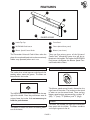
FEATURES
1
2
5
0
1
2
3
3
4
6
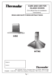
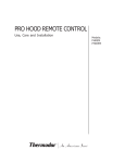
RAISED INTAKE
1
Intake Top Cap
4
Front Panel
2
UP/DOWN Push-button
5
Filters (behind front panel)
3
Blower Speed Control Knob
6
Blower (not shown)
The Thermador Universal Cook‘n’Vent® takes the
place of an overhead hood and can be conveniently
hidden away (lowered) when not in use.
There are five primary parts of the Universal
Cook‘n’Vent® downdraft system that will be referred to in this booklet: The Intake, the UP/DOWN
Push-button, the Blower, the Blower Speed Control Knob and the Filters.
The Intake
The Blower Speed Control Knob
The intake, when raised, captures and channels the
cooking odors, steam and grease. The filters are
located within the intake.
0
1
2
3
UP/DOWN Push-button
The UP/DOWN push-button is located on the top
right of the intake. Press the push-button once to
raise or lower the intake. It is not necessary to
hold the push-button.
The Blower
The blower is the fan that draws the cooking odors
out of the house.
The blower speed control knob is located on the
right front of the intake. The intake must be raised
in order to use the control knob. There are four
blower speed settings represented by numbers "0"
(Off) , "1" (Low), "2" (Medium), and "3" (High).
Filters
The filters are located just behind the removable
front panel with the Intake. The filters condense
and trap the grease in the air.
PAGE 3
OPERATION
For Best Results
•
•
•
•
•
To Set or Adjust Blower Speed
Turn the blower on before starting to cook.
A higher heat setting may be needed when the
Cook‘n'Vent® is in operation.
Use a rear burner when browning or pan frying
meat.
Open a window or inside door slightly.
Clean the intake front panel and back wall and filters after each use.
For Gas Cooktops, a lower blower speed should be
used if:
• the gas flame is being distorted by the air movement,
• the burner continually sparks (clicks), or
• the burner flame repeatedly blows out.
To Raise the Intake
•
•
•
•
Vary the blower speed as needed for the food or
the cooking method being used. For example: greasy
or pungent foods require greater ventilation power
than boiling pasta.
To Lower the Intake
•
•
Press the UP/DOWN push-button once.
The blower, if operating when the UP/DOWN pushbutton is pressed, will turn off when the intake is
lowered.
To Stop Intake While It is Moving
Press the UP/DOWN push-button once.
• The intake will stop.
• Press the UP/DOWN push-button again to complete the cycle.
Press the UP/DOWN push-button once to raise
the intake.
The intake will stop automatically at its maximum
height.
The blower will automatically turn on to the previously set blower speed.
PAGE 4
CARE AND CLEANING
The efficiency of the Cook‘n’Vent® downdraft ventilation system depends on the cleanliness of the intake
and filters. The frequency of cleaning depends on the
amount and type of cooking.
•
Do not use the ventilating system without the filters in place or with grease-laden filters or surfaces.
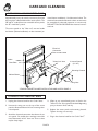
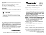
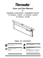
To Clean the Intake
Intake must be in the raised position to clean.
1. Turn Off the blower ("O").
2. Grasp the removable front panel at the top near
the sides and pull up and then forward. Set aside.
3. Remove filters.
A or D
Support Bar
E
C
0
1
2
3
Support Bar
Back Wall
B
•
•
•
Slats
Always use the mildest cleaner that will do the job. Use clean, soft cloths, sponges or paper towels.
Rub stainless steel finishes in the direction of the grain. Wipe area dry to avoid water marks.
After cleaning, place all parts in their proper positions before using the Cook‘n’Vent®.
The cleaners recommended below indicate a type and do not constitute an endorsement. Use all products
according to package directions.
A
Anodized
Aluminum
Top Cap for
Stainless
Top cap is not removable.Wash top and underside with hot sudsy water. Rinse and wipe dry or
apply Fantastic® or Formula 409® first to a clean sponge or paper towel and wipe clean. DO NOT
USE powdered cleansers or steel wool pads.
B
Aluminum
Clean filters in the dishwasher or by agitating in sudsy water. Ensure that there is no soil
trapped in the fine mesh. Dry the filters before reinstalling them.
Mesh Filters
C
Plastic
UP/DOWN
Push-button,
Control Knob
DO NOT REMOVE push-button or control knob. Wipe with a moist soapy sponge. Rinse and
dry.
D
Painted
Top Cap for
Black/White
Top cap is not removable.Wash top and underside with hot sudsy water. Rinse and wipe dry or
apply Fantastik® or Formula 409® first to a clean sponge or paper towel and wipe clean. DO
NOT USE powdered cleansers or steel wool pads.
E
Stainless
Steel
Front Panel
& Back Wall
Wipe grease accumulation with a paper towel or sponge. Scrape heavy buildup with a plastic
spatula. Clean with a soapy sponge; rinse and dry. Always wipe or rub with grain. Wipe with
Fantastik® or Formula 409® sprayed onto a paper towel. If grease buildup is heavy, several
applications may be necessary.
Polish with Revere Ware® Metal Polish or Stainless Steel Magic® and a soft cloth. Remove
water spots with a cloth dampened with white vinegar. Use Revere Ware® Instant Stainless
Steel Cleaner to remove heat discoloration.
To Re-Assemble the Intake
1. Place the filters inside the intake, side by side, on
the slats in front of the back wall. They will lean
forward and the tops of the outside two will rest
against the support bars.
2. Holding the front panel at the top near the sides,
place bottom edge over front lower sill of the intake.
3. Keeping the panel vertical, hook the top of the front
panel to the intake.
PAGE 5
CARE AND CLEANING
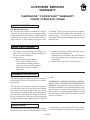
OCCASIONAL COOK‘N’VENT® CARE
Approximately every six months, remove any food soil
that may have collected behind the access panels. The
30" and 36" models have two removable access panels;
the 45" model has 3 panels.
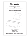
mote blower installation). See illustration below. The
electrical connection box above the clean out area must
be accessible for electrical inspection or service only.
DO NOT TOUCH OR CLEAN the electrical connection box.
The access panels to the "clean out" area are beside
the blower (cabinet installation) or duct transition (re-
Electrical
Connection
Box: DO NOT OPEN
Intake
"Clean Out" Area
Data Plate
2 Access Panels
(3 in 45")
Mounting Channel
Cabinet Blower
Wing Nuts
VTN600R CABINET BLOWER INSTALLATION AND ACCESS PANELS
TO REACH THE CLEAN OUT AREA
1. Unplug the electrical cord for the Cook‘n’Vent®.
2.
Unscrew the wing nuts on the top of the access
panels as illustrated above. Lift out mounting channel and panels.
3. Avoid the electrical connection box above the access panels. Be careful when working around the
metal framework of the" clean out" area as there
may be sharp edges.
4. Wipe up any accumulated grease or food in the
"clean out" area. Use a general household degreasing
spray or cleaner. Rinse and dry.
5. Replace the access panels and mounting channel.
Tighten the wing nuts securely.
6. Plug in the electrical cord for the Cook‘n’Vent®.
PAGE 6
CUSTOMER SERVICES
WARRANTY
THERMADOR ® COOK‘N’VENT ® WARRANTY
CVS30R, CVS36R AND CVS45R
WHAT IS COVERED
Full One Year Warranty
For one year from the date of installation or date of
occupancy for a new previously unoccupied dwelling,
any part which fails in normal home use will be repaired
or replaced free of charge. Save your dated receipt or
other evidence of the installation/occupancy date.
Thermador® will pay for all repair labor and replacement parts found to be defective due to materials and
workmanship. Service must be provided by a
Thermador® Authorized Service Agency during normal
working hours.
WHAT IS NOT COVERED
1. Service by an unauthorized agency. Damage or repairs due to service by an unauthorized agency or
the use of unauthorized parts.
2. Service visits to:
• Teach you how to use the appliance.
• Correct the installation. You are
responsible for providing electrical
wiring and other connecting facilities.
• Reset circuit breakers or replace
home fuses.
3. Damage resulting from accident, alteration, misuse,
abuse, improper installation or
installation not in accordance with local electrical
codes or plumbing codes, or improper storage of
the appliance.
4. Repairs due to other than normal home use.
WARRANTY APPLICATION
This warranty applies to appliances used in normal family households. It does not cover their use in commercial situations.
This warranty is for products purchased and retained
in the 50 states of the U.S.A., the District of Columbia
and Canada. The warranty applies even if you should
move during the warranty period. Should the appliance
be sold by the original purchaser during the warranty
period, the new owner continues to be protected until
the expiration date of the original purchaser’s warranty
period.
THERMADOR ® DOES NOT ASSUME ANY RESPONSIBILITY FOR INCIDENTAL OR CONSEQUENTIAL
DAMAGES. Some states do not allow the exclusion or
limitation of incidental or consequential damages, so the
above limitation or exclusion may not apply to you. This
warranty gives you specific legal rights and you may also
have other rights which may vary from state to state or
province to province.
SERVICE DATA
For handy reference, the serial tag information has been
affixed to the back cover. For location of the serial tag
on the product see the back cover. Keep your invoice
for warranty validation.To obtain service, see back cover.
PAGE 7
CUSTOMER SERVICES
BEFORE CALLING FOR SERVICE
•
Ensure that the electrical cord is properly
connected and the supply circuit is energized.
If the blower does not operate:
• Check that the intake is fully raised.
• Make sure that the blower speed control
knob is not in the OFF position, "0".
HOW TO OBTAIN SERVICE
For authorized service or parts information, call 1-800-735-4328.
We want you to be a satisfied customer. If a situation arises that has not been resolved to your
satisfaction, please let us know.
Write: Customer Support, Thermador®, 5551 McFadden Ave., Huntington Beach, CA 92649, or call:
1-800-735-4328.
Please include the Model Number, Serial Number (listed below), and Date of Original Purchase/
Installation.
Serial Number/Data Plate Location: Above
Electrical Connection Box. SeePage 6.
We reserve the right to change specifications or design without notice. Some models are certified for use in
Canada. Thermador® is not responsible for products which are transported from the U.S. for use in Canada.
Check with your local Canadian distributor or dealer.
UL LISTED
FILE # E21958
BSH Home Appliances Corp.
5551 McFadden Avenue, Huntington Beach, CA 92649 • 800/735-4328
ECO 71602 • 5060002295 • 19-12-202E • © 2003 BSH Home Appliances Corp. • Litho in U. S. A. 5/03
PAGE 8