1
ADEMCO Optiflex
Video Controller
Installation and Setup Guide
K0948V2 11/04 Rev. A
Table of Contents
• • • • • • • • • • • • • • • • • • • • • • • • • • • • • • • • • • • • • • • • • • • • • • • • •
Ssection 1: General Information .......................................................................................................... 1-1
Introduction to Optiflex........................................................................................................................................................1-1
Optiflex Features ..................................................................................................................................................................1-1
General Features...............................................................................................................................................................1-1
Secure Remote Viewing ...................................................................................................................................................1-1
Optiflex Typical System Block Diagram .............................................................................................................................1-2
Section 2: Mounting, Wiring, and Setup ............................................................................................. 2-1
Setup Considerations............................................................................................................................................................2-1
Mounting Optiflex................................................................................................................................................................2-2
Wiring and Setup of Optiflex ...............................................................................................................................................2-3
NTSC Output Configuration ............................................................................................................................................2-5
NTSC Guard Tour Mode (Camera Scanning Mode) – Camera Dwell Time ..................................................................2-5
NTSC Guard Tour Mode – Camera Selection..................................................................................................................2-5
Section 3: Setting Up Optiflex Using Symphony ................................................................................ 3-1
How to Enable Video on Symphony ....................................................................................................................................3-1
How to Set Up Video Options on Symphony.......................................................................................................................3-2
Section 4: Operational Status Indicators............................................................................................. 4-1
Camera Status LEDs ............................................................................................................................................................4-1
Network Status LEDs ...........................................................................................................................................................4-1
Optiflex Status LEDs............................................................................................................................................................4-2
Camera Status...................................................................................................................................................................4-2
Camera Activity ...............................................................................................................................................................4-2
Power................................................................................................................................................................................4-2
Section 5: Specifications........................................................................................................................ 5-1
Specifications .......................................................................................................................................................................5-1
Section 6: Summary of Connections .................................................................................................... 6-1
i
S E C T I O N
1
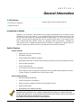
General Information
• • • • • • • • • • • • • • • • • • • • • • • • • • • • • • • • • • • • • • • • • • • • • • • • •
In This Section
♦ Introduction to Optiflex
♦ Optiflex Typical System Block Diagram
♦ Optiflex Features
• • • • • • • • • • • • • • • • • • • • • • • • • • • • • • • • • • • • • • • • • • • • • • • • •
Introduction to Optiflex
Optiflex is an interactive Video System that provides multiplexed local and remote video
monitoring for up to six cameras. It can temporarily save up to 10 frames from each of the
six cameras (video frames are stored internally in JPEG format) at a rate of one frame per
second. Cameras can be triggered either by an external voltage source, or by system events
from a Honeywell Vista security system (e.g., burglary alarm at front door). Optiflex can
also interface with a Symphony Advanced User Interface via Ethernet to display video on
demand. Images may also be viewed on a stand-alone video monitor if desired.
Optiflex Features
General Features
• Support for up to six camera inputs
•
One Monitor Output
•
Integral 4204 Relay Module capability
•
Selectable Dwell Time for Guard Tour Viewing (sequential scanning of multiple cameras)
•
Time and Date Stamping
•
Camera Identification
•
Local and/or remote viewing capabilities
•
Video captures (up to 19 captures of 10 frames each) viewable through Optiflex Connect
(remote viewing) or Optiflex Direct (local viewing on PC)
Secure Remote Viewing
•
Firewall friendly installation
•
Video Transmission via Ethernet
•
Remote viewing of multiple locations using Optiflex Connect
•
Password Protection
•
Selectable Single or Multiple Display
Optiflex Connect is required for remote viewing of video images over the Internet. Optiflex Direct is
required for local viewing on a PC. Neither is required for local viewing at a monitor connected
directly to the Optiflex unit. For information on how to obtain these services and set your system up
for remote viewing and local viewing on a PC, log on to
http://www.security.honeywell.com/hsce/alarmnet/optiflex.
1-1
Optiflex Installation and Setup Guide
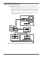
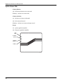
Optiflex Typical System Block Diagram
A typical Optiflex System Block Diagram is shown in Figure 1. Optiflex can be used in a
variety of applications. It can be:
•
connected through an Ethernet hub/router to a PC or Symphony for remote viewing
•
programmed in the control panel to be triggered by selected events of the security
system, and viewed locally on a Symphony connected to the security system control
panel
•
used as a standalone system with only a monitor or a Symphony for local viewing
•
configured for all of the above.
Figure 1. Optiflex System Block Diagram Showing Possible Configurations
1-2
S E C T I O N
2
Mounting, Wiring, and Setup
• • • • • • • • • • • • • • • • • • • • • • • • • • • • • • • • • • • • • • • • • • • • • • • • •
In This Section
♦ Wiring and Setup of Optiflex
♦ Setup Considerations
♦ Mounting Optiflex
• • • • • • • • • • • • • • • • • • • • • • • • • • • • • • • • • • • • • • • • • • • • • • • • •
Setup Considerations
Cameras connected to Optiflex can either be triggered by system events from a Honeywell
Vista control panel, from the voltage triggers provided, or both. Optiflex can also be used
without any triggers at all, if the system is configured to automatically scan the cameras one
at a time, or if the cameras are always on. If using the voltage triggers, refer to the table
below to determine which camera each voltage trigger turns on.
Voltage Trigger
Function
1
Captures Video on Camera 1
2
Captures Video on Camera 2
3
Captures Video on Camera 3
4
Captures Video on Camera 4
5
Captures Video on Camera 5
6
Captures Video on Camera 6
7
NTSC Advance
8
Captures Video on All Cameras
If using a Honeywell Vista control panel, the cameras are turned on using Output (relay)
Programming commands in the control panel. To accomplish this, enable a 4204 Relay
Module in the system’s Device Programming Mode as Device Address 12. Then program
eight logical relays and point to the same four physical relays twice, programmed as shown
in the table below, using system events or zones/zone lists as desired to turn on the relays as
shown below. Cameras are turned on through the ECP (Data In and Data Out) connections
(See “Wiring and Setup of Optiflex”) in this section, and the control panel’s Programming
Guide for information on how to program output relays.
4204 Output Command (4204 on ECP Address 12)
Function
Relay 1: Turn ON for 2 seconds
Captures Video on Camera 1
Relay 2: Turn ON for 2 seconds
Captures Video on Camera 2
Relay 3: Turn ON for 2 seconds
Captures Video on Camera 3
Relay 1: Continuous Pulse
Captures Video on Camera 4
Relay 2: Continuous Pulse
Captures Video on Camera 5
Relay 3: Continuous Pulse
Captures Video on Camera 6
Relay 4: Continuous Pulse
NTSC Advance
Relay 4: Turn ON for 2 seconds
Captures Video on All Cameras
2-1
Optiflex Installation and Setup Guide
• Voltage Trigger and Output Programming commands are interchangeable for turning on a
camera.
• “All Cameras” function captures a single frame from each camera.
• NTSC Advance function allows you to step through the video of all cameras sequentially,
one camera at a time, and then the Guard Tour. It does not support video capturing.
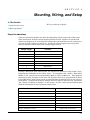
Mounting Optiflex
Optiflex must be mounted indoors.
following steps:
To mount Optiflex, see Figure 2 and complete the
1. Detach the case back by pushing up into the two tabs located at the bottom of Optiflex
with the blade of a screwdriver while pulling the case back and case front apart.
2. Locate the case back over the mounting surface such that the opening in the case back is
aligned with the wire/cable access opening (in the mounting surface) while passing the
wires/cable through the opening in the case back.
3. Secure the case back to the mounting surface using four screws (supplied).
Prior to attaching the case front to the case back, be sure to wire the Optiflex as described in the
"Wiring Optiflex" paragraph in this section.
MOUNTING
SCREW
(TYP)
(4)
ON
1
2
3
4
5
6
7
8
WALL OR
MOUNTING
SURFACE
REAR
COVER
PANEL
FRONT COVER
PANEL
Figure 2. Mounting Optiflex
2-2
optiplex-002-V2
Section 2: Mounting and Wiring
Wiring and Setup of Optiflex
Before wiring Optiflex, make sure power is turned off and review the important notes below.
1. Use a Listed Class 2 power supply suited for the application (see Section 5:
Specifications).
2. Panel triggered UL Installations: Optiflex may be connected as a supplemental device to
listed fire and/or burglar alarm control panels that support the 4204 relay module except
as noted below.
UL
•
In UL installations, Optiflex may be connected to panels that have ground fault
detection only if the local authority having jurisdiction allows the ground fault
detection feature to be disabled.
•
In non-UL installations requiring ground fault detection, when possible, use cameras
powered by a power source such as a plug-in transformer that is not earth grounded
and isolate the camera's mounting brackets from earth ground. Connect a video
ground loop isolation device such as Vicon's V235GLTA Ground Loop Transformer
to the coaxial cable that runs between Optiflex and the video monitor or recorder (or
camera if required) causing the ground fault. Video ground loop isolation devices
are not UL listed and may not be used in UL installations.
Optiflex is supplied with a header connector. Insert wires into the connector and secure
by placing the header arms in the down position (see Figure 3). When all wires are
secured, mount the header on Optiflex by snapping into place.
AUI-016-V0
Figure 3. Header Connector
2-3
Optiflex Installation and Setup Guide
To wire Optiflex, refer to the Summary of Connections diagram at the rear of this guide and
do the following.
1. Connect the wires to the header as follows:
a. Connect the (+) terminal of the supplementary power supply to header position 1
(+12VDC terminal of Optiflex (red wire)).
b. Connect the (–) terminal of the supplementary power supply to header position 2
(Gnd terminal of Optiflex (black wire)).
• A separate 12VDC supplementary power supply is strongly recommended. Failure to
provide 12VDC, 1 A (minimum) can result in Optiflex not functioning correctly.
• If cameras are to be powered by Optiflex, total current cannot exceed 1A.
• MAKE SURE ALL SYSTEM GROUNDS ARE CONNECTED TOGETHER!
•
2. If using system events from a Honeywell Vista control panel to turn on the cameras,
c.
Connect the Data In terminal of the control panel to header position 3 (Data Out
terminal of Optiflex (green wire)).
d. Connect the Data Out terminal of the control panel to header position 4 (Data In
terminal of Optiflex (yellow wire)).
UL
Use a Listed cable/DSL router suited for the application.
3. If using remote viewing over Ethernet, connect the LAN cable (Category 5) between the
Optiflex Ethernet connector and the hub/router LAN connector.
4. Connect a cable (Category 5) from the camera to one of the Optiflex camera connectors.
Up to six cameras can be connected, one to each port.
Optionally, coaxial cable may be used for video wiring. Use Honeywell part number
OPTICOAX-1 (single coax to RJ45) or Honeywell part number OPTICOAX-3 (triple
coax to RJ45).
5. Connect coax from the composite video out connector on Optiflex to the composite video in
connector on the monitor. If the monitor does not have a composite video connection, you
can make the conversion using an RF modulator cable, available from a general
electronics store.
6. If using auxiliary voltage triggers instead of (or in addition to) panel events to turn on the
cameras, connect active high voltage trigger wiring to the 9-pin block. See Section 8:
Summary of Connections for connection information.
7. Set DIP switches according to desired operation, referring to the tables that follow.
2-4
Section 2: Mounting and Wiring
NTSC Output Configuration
Selects either one camera or guard tour (camera scanning) for default local viewing through
a monitor.
Dip
Switch
Cam-1
View
Cam-2
View
Cam-3
View
Cam-4
View
Cam-5
View
Cam-6
View
Guard
Tour
Reserved
1
OFF
ON
OFF
ON
OFF
ON
ON
OFF
2
OFF
OFF
ON
ON
OFF
OFF
ON
ON
3
OFF
OFF
OFF
OFF
ON
ON
ON
ON
NTSC Guard Tour Mode (Camera Scanning Mode) – Camera Dwell Time
Selects the amount of time to remain on each camera before scanning to the next.
Dip
Switch
2 sec
4 sec
8 sec
16 sec
4
OFF
ON
OFF
ON
5
OFF
OFF
ON
ON
NTSC Guard Tour Mode – Camera Selection
Dip
Switch
Use All Six Cameras
for Guard Tour
Use First Four
Cameras for Guard
Tour
6
OFF
ON
8. Turn on the power source. Wait approximately 30 seconds while the Optiflex software
loads and the video sources are detected. During this time Optiflex scans for cameras,
and if they are detected begins monitoring them. If they are not detected, they will not
be monitored.
•
During the boot-up process the cover should be removed to enable the installer to view
status LEDs.
•
If a new camera is added after the initial boot–up process, power must be turned off and
reapplied for the new camera to be detected.
9. After the unit is powered up, check the following:
Power LED is ON.
Camera LED is ON for each connected camera.
If connected to the Ethernet hub/router Network LINK LED is ON.
Network SELECT, TX and RX LEDs may be flashing.
2-5
Optiflex Installation and Setup Guide
Optiflex can be reset to its default settings by pressing and holding the top reset button for 10
seconds. The system will automatically reboot to the default settings
2-6
S E C T I O N
3
Setting Up Optiflex Using Symphony
• • • • • • • • • • • • • • • • • • • • • • • • • • • • • • • • • • • • • • • • • • • • • • • • •
In This Section
♦ How to Select Video from the System Options
♦ How to Set Up Video Options on the Symphony
• • • • • • • • • • • • • • • • • • • • • • • • • • • • • • • • • • • • • • • • • • • • • • • • •
How to Enable Video on Symphony
Symphony can either be used to view video events locally when attached to a Honeywell
Vista control panel, or to view events remotely over the Internet using Optiflex Connect. In
either case, follow the steps below to allow the viewing of video events through Symphony.
Symphony allows you to place buttons on the "Home" screen. The SECURITY button is
always displayed and cannot be removed. Buttons that can be added are Video, Lighting,
and Heating/Cooling. Prior to Video setup, the “Home” screen VIDEO button should be
selected from the Options screen. To avoid confusion to the user, only buttons whose options
are functional in the system should be displayed. To enable video, do the following:
1. Press the SECURITY button on the “Home” screen. The “Arming” screen is displayed.
2. Press the MORE CHOICES button. The “More Choices” screen is displayed.
3. Press the SETUP button on the “More Choices” screen. The “Setup” screen is displayed.
4. Press the ADVANCED SETUP button. The Enter Authorized Code: authorization
screen is displayed.
5. Enter your 4-digit Installer code. The “Advanced Setup” menu screen is displayed.
6. Press the Central Station button. The “Central Station” menu screen is displayed.
7. Press the Options button on the “Central Station” screen. A pop-up window is displayed
with options for selecting Lighting, Heating/Cooling and Video. Click on the button
corresponding to Video. A checkmark will appear in the button indicating that the video
option has been selected.
8. Press the Done button to accept the setting. Symphony returns to the "Central Station"
menu screen.
3-1
Optiflex Installation and Setup Guide
How to Set Up Video Options on Symphony
1.
Press the SECURITY button on the “Home” screen. The “Arming” screen is displayed.
2. Press the MORE CHOICES button. The “More Choices” screen is displayed.
3. Press the SETUP button on the “More Choices” screen. The “Setup” screen is displayed.
4. Press the ADVANCED SETUP button.
displayed.
The “Enter Authorized Code:” screen is
5. Enter your 4-digit Installer code. The “Advanced Setup” menu screen is displayed.
6. Press the Video Setup button. The “Video Setup” screen is displayed.
7. Edit Camera-1 name and label and position.
camera.
Save the data.
Repeat this for each
8. Select default camera for local viewing on Symphony.
9. Select NTSC default camera for NTSC composite monitor viewing.
In order to enable remote viewing over the Internet using either Symphony or a PC, you must
obtain Optiflex Connect through AlarmNet. For information on how to set your system up for
remote viewing, go to http://www.security.honeywell.com/hsce/alarmnet/optiflex.
3-2
S E C T I O N
4
Operational Status Indicators
• • • • • • • • • • • • • • • • • • • • • • • • • • • • • • • • • • • • • • • • • • • • • • • • •
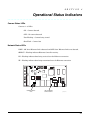
Camera Status LEDs
Cameras 1 – 6 LEDs
ON – Camera detected
OFF – No camera detected
Fast Flashing – Camera being viewed
Slow Flash – Camera lost
Network Status LEDs
LINK – ON when Ethernet link is detected and OFF when Ethernet link is not detected.
SELECT – Flashing indicates Ethernet Controller activity.
RX – Flashing indicates data being received over the Ethernet connection.
TX – Flashing indicates data being transmitted over the Ethernet connection.
ON
12345678
CAMERA STATUS
LEDs
LEDs ETHERNET
STATUS LIGHTS
optiflex-007-V0
4-1
Optiflex Installation and Setup Guide
Optiflex Status LEDs
Camera Status
Off – All detected cameras are connected
Flashing – At least one camera lost.
Camera Activity
On – At least one camera is detected
Off – No cameras detected
Flashing – At least one camera is being viewed
Power
On – power applied to Optiflex
Off – No power applied to Optiflex
NOT
USED
CAMERA
STATUS
CAMERA
ACTIVITY
POWER)
optiflex-006-V0
4-2
S E C T I O N
5
Specifications
• • • • • • • • • • • • • • • • • • • • • • • • • • • • • • • • • • • • • • • • • • • • • • • • •
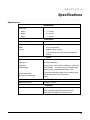
Specifications
MECHANICAL
Dimensions:
Width
7 ½ inches
Height
6 ½ inches
Depth
1 ¼ inches
ELECTRICAL
Operating Voltage:
Power:
12VDC nominal
Video:
1V p-p Unbalanced
Current:
600mA, without camera
1.0A maximum with cameras being powered by
Optiflex
VIDEO
Video Standard:
NTSC
Video Inputs:
Six RJ45 connectors
Resolution:
Single camera - 320 x 240, Quad Display – 160 x 120
Video Storage:
Flash Memory – 19 captures of up to 10 frames each
(oldest images are deleted when buffer is full)
Local Refresh Rate:
Compression Technology:
Four frames/second for single camera viewing. Quad
view approximately one frame/second.
JPEG
NETWORK
WAN/LAN Interface:
10 Base-T Ethernet
TRIGGERS
Event Driven Video Capture
Eight 12VDC positive triggers
Eight integrated 4204 style relays for use with
Honeywell compatible Vista Control Panels
5-1
Optiflex Installation and Setup Guide
5-2
S E C T I O N
6
Summary of Connections
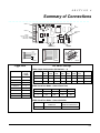
• • • • • • • • • • • • • • • • • • • • • • • • • • • • • • • • • • • • • • • • • • • • • • • • •
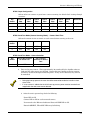
DETAIL A
DIP
SWITCH
DETAIL B
COMPOSITE
VIDEO
OUT
ON
12345678
PRESS
AND HOLD BOTH
(10 SECONDS)
UNIT RESET
CAMERA INPUTS
(DETAIL C)
10 baseT
ETHERNET
3
TRIGGER 1
TRIGGER 2
TRIGGER 3
TRIGGER 4
TRIGGER 5
TRIGGER 6
TRIGGER 7
TRIGGER 8
GND
+12V
-GND
ECP GRN
ECP YEL
N.C.
DETAIL A
1
5
6
4
2
DETAIL B
DETAIL C
optiflex-SOC-V3
Trigger Data
DIP Switch Settings
NTSC Output Configuration (DIP Switch 1 – 3)
Function
Voltage
Trigger
(+12VDC)
Camera 1
1
Camera 2
2
Camera 3
3
Camera 4
4
Camera 5
5
Camera 6
6
NTSC Advance
7
All Cameras
8
Dip Switch
Cam-1
View
Cam-2
View
Cam-3
View
Cam-4
View
Cam-5
View
Cam-6
View
Guard
Tour
Reserved
1
OFF
ON
OFF
ON
OFF
ON
ON
OFF
2
OFF
OFF
ON
ON
OFF
OFF
ON
ON
3
OFF
OFF
OFF
OFF
ON
ON
ON
ON
NTSC Guard Tour Mode – Camera Dwell Time
Dip Switch
2 sec
4 sec
8 sec
4
5
16 sec
OFF
ON
OFF
ON
OFF
OFF
ON
ON
NTSC Guard Tour Mode – Camera Selection
Dip Switch
Use All Six Cameras for
Guard Tour
Use the First Four
Cameras for Guard Tour
6
OFF
ON
6-1
Optiflex Installation and Setup Guide
6-2
NOTES
NOTES
LIMITED WARRANTY
Honeywell International Inc., acting through its Security & Custom Electronics business ("Seller") 165
Eileen Way, Syosset, New York 11791, warrants its product(s) to be in conformance with its own plans
and specifications and to be free from defects in materials and workmanship under normal use and
service for 24 months from the date stamp control on the product(s) or, for product(s) not having a
manufacturer’s date stamp, for 12 months from date of original purchase unless the installation
instructions or catalog sets forth a shorter period, in which case the shorter period shall apply. Seller's
obligation shall be limited to repairing or replacing, at its option, free of charge for materials or labor,
any product(s) which is proved not in compliance with Seller's specifications or proves defective in
materials or workmanship under normal use and service. Seller shall have no obligation under this
Limited Warranty or otherwise if the product(s) is altered or improperly repaired or serviced by anyone
other than Honeywell factory service. Connection of any device(s) to a communicating bus of a Honeywell
security system (e.g., keypad bus, polling loop) other than those manufactured or approved by Honeywell
shall void this warranty. For warranty service, return product(s) transportation prepaid, to Honeywell
Factory Service, 165 Eileen Way, Syosset, New York 11791.
THERE ARE NO WARRANTIES, EXPRESS OR IMPLIED, OF MERCHANTABILITY, OR FITNESS
FOR A PARTICULAR PURPOSE OR OTHERWISE, WHICH EXTEND BEYOND THE DESCRIPTION
ON THE FACE HEREOF. IN NO CASE SHALL SELLER BE LIABLE TO ANYONE FOR ANY
CONSEQUENTIAL OR INCIDENTAL DAMAGES FOR BREACH OF THIS OR ANY OTHER
WARRANTY, EXPRESS OR IMPLIED, OR UPON ANY OTHER BASIS OF LIABILITY
WHATSOEVER, EVEN IF THE LOSS OR DAMAGE IS CAUSED BY THE SELLER'S OWN
NEGLIGENCE OR FAULT.
Seller does not represent that the product(s) it sells may not be compromised or circumvented; that the
product(s) will prevent any personal injury or property loss by burglary, robbery, fire or otherwise; or
that the product(s) will in all cases provide adequate warning or protection. Customer understands that
a properly installed and maintained alarm system may only reduce the risk of a burglary, robbery, fire,
or other events occurring without providing an alarm, but it is not insurance or a guarantee that such
will not occur or that there will be no personal injury or property loss as a result. CONSEQUENTLY,
SELLER SHALL HAVE NO LIABILITY FOR ANY PERSONAL INJURY, PROPERTY DAMAGE OR
OTHER LOSS BASED ON A CLAIM THAT THE PRODUCT(S) FAILED TO GIVE WARNING.
HOWEVER, IF SELLER IS HELD LIABLE, WHETHER DIRECTLY OR INDIRECTLY, FOR ANY
LOSS OR DAMAGE ARISING UNDER THIS LIMITED WARRANTY OR OTHERWISE, REGARDLESS
OF CAUSE OR ORIGIN, SELLER'S MAXIMUM LIABILITY SHALL NOT IN ANY CASE EXCEED
THE PURCHASE PRICE OF THE PRODUCT(S), WHICH SHALL BE THE COMPLETE AND
EXCLUSIVE REMEDY AGAINST SELLER.
This warranty replaces any previous warranties and is the only warranty made by Seller on this
product(s). No increase or alteration, written or verbal, of the obligations of this Limited Warranty is
authorized.
165 Eileen Way, Syosset, NY 11791
Copyright 2004 Honeywell International Inc.
www.honeywell.com/security
ÊK0948V2pŠ
K0948V2 11/04 Rev. A