1
LENNOX
INSTALLATION
INSTRUCTIONS
_2001 Lennox Industt]e-_ _nc
Dallas Texas USA
G32Q SERIES
UNITS
GAS UNITS
504,488M
11/2001
_[_2ech
Supersedes504,382M
ITahi6 of_ _ _te:nts
RETAIN THESE INSTRUCTIONS
FOR FUTURE REFERENCE
nical
blications
Litho U.S.A.
i
::
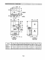
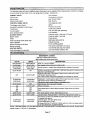
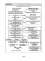
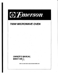
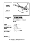
Unit Dimensions ................................
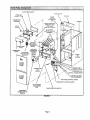
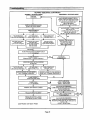
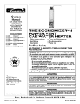
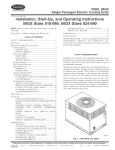
G32Q Parts Arrangement .......................
Requirements ..................................
General .......................................
Installation - Setting Equipment ..................
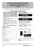
Return Air Opening Guidelines ...................
Filters & Optional Filter Assembly .................
Duct System ...................................
Pipe & Fittings Specifications ....................
Vent Piping L_uidelines..........................
Joint Cementing Procedure ......................
Venting Practices ...............................
Gas Piping ...................................
Electrical .....................................
Unit Start-Up .................................
Heating Sequence of Operation .................
Blower Operation ..............................
Gas Pressure Adjustment ......................
High Altitude Information .......................
Other Unit Adjustments ........................
Service ......................................
Repair Parts ..................................
Troubleshooting ...............................
Start-Up & Performance Checklist .
2
3
4
5
5
5
6
7
7
8
8
9
15
16
21
22
22
22
23
23
24
27
27
32
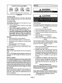
-AWARNING
WHAT TO DO IF YOU SMELL GAS:
Do not store or use gasoline or other
flammable vapors and liquids in the vicinity of this or any other appliance.
Installation
and service must be performed by a qualified installer, service
agency or the gas supplier,
• Do not by to light any appliance.
• Extinguish any open flames.
• Do not touch any electrical switch; do not use
any phone in your building.
• Immediately call your gas supplier from a
neighbor's phone. Follow the gas supplier's
instructions.
• If you cannot reach your gas supplier, call the
fire department.
11101
IIIIIIIIIlHIIIIIIHIIIIIIIIIIIIIIIIII
504,488M
Pagol
IIIIHIIIIIIIIllllIIHHItllUlI
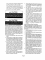
1 1116
3 5/8
1 1116
(41)
,o-oI
_8
(16)'-IP
•
v
AIR OUTLET
151 )
TOP VIEW
"ql'--
28 1/2
(724)
,lira
I
I
T
T
21 3/4
(552)
A_
I
I
m
46
(1168)
ELECTRICA
INLETS_
{BothSides)
EXTERNAL
SIDE RETURN
/_R FIL'I1ERK]T
(Either Side
O_onal
,
GAS PIPING
INLET
(Both
t
Sides)
AIR FLOW
91- 4(102)
L
_____(Either Side) J
Lt:;:"ZtJ
4 (I02)
E-IP
Return Air
Knockout (Bottom)
Return Air
Knockout (Bottom)
SIDE VIEW
FRONT VIEW
A
Model No.
B
C
D
E
F
G
H
in.
I mm
in.
mm
in.
mm
In,
mm
In.
mm
in.
mm
in.
mm
in,
mm
G32Q3-75
16-1/4
413
14.1/8
359
12
305
12
305
2-118
54
7-5/8
194
14
356
12-3/4
324
G32Q3/4-100
G32(_4/5-100
21-1/4
540
19-1/8
486
18
457
18
457
1-5/8
41
10-1/8
257
20
508
18-3/4
476
G32Q4/5-125
26-1/4
667
24-1/8
613
18
457
18
457
4-1/8
105
12-5/8
321
20
508
18-3/4
476
Page 2
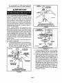
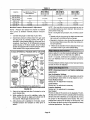
GLASS FIBER GASKET
FLUE COLLAR
FRESH AIR
INTAKE FITTING
TOP CAP
HEADER
BURNERBOX
ASSEMBLY
.
/
/
PATCH
_I
BOX
(COLLECTORTH_
_
PATCH PLATE WITH
l
BARBED FITTING
WARM
AND FLAME
ROLL-OUT SWITCH
CABINET
FLUE
DuralokPlus TM
HEAT EXCHANGER
ASSEMBLY
FLAME SIGHT p
GLASS
/
BURNER BOX
/
COVER
]3NO-STAGE
GAS VALVE AND
MANIFOLD
RESSURE-.
swrrcH
HIGH HEAT
PRESSURE
SWITCH
(-75 only)
4.
S/"
SUPPLY
AIR
_
BLOWER
BURNER
ACCESS
PANEL
AIR
ORIFICE
CONDENSERCOIL
CONTROL TRANSFORMER
BLOWER
ACCESS
DOOR
CONTROL VOLTAGE
CIRCUIT BREAKER
z-/"
TWO-STAGE CONTROL BOARD
LBOARD
COLD HEADER
(COLLECTOR)
BOX
DOOR INTERLOCK SWITCH
TWO-SPEED
COMBUSTION AIR
INDUCER
FIGURE 1
Page 3
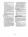
Lennox G32Q units are CSA International
ANSI Z21.47 and CSA 2.3 standards.
In the USA, installation
of Lennox
certified
to
ing units to avoid condensation in the heating compartment. With a parallel flow arrangement, a damper (or oth-
gas central furnaces
must conform with local building codes. In the absence of
local codes, units must be installed according to the current National Fuel Gas Code (ANSI-Z223.1) in the United
States. The National Fuel Gas Code is available from the
following address:
Amedcan National Standards
11 West 42rid Street
Institute,
When the furnace is used with cooling units, it shall be
installed in parallel with, or on the upstream side of. cool-
er means to control the flow of air) must adequately
prevent chilled air from entering the furnace. If the damper is manually operated, it must be equipped to prevent
operation of either the heating or the cooling unit, unless it
is in the full =HEAT" or "COOL" setting.
When installed, the furnace must be electrically grounded
according to local codes. In addition, in the United States,
installation must conform with the current National Electric Code, ANSI/NFPA No. 70. The National Electric Code
Inc.
New York, NY 10036
In Canada, installation must conform with current National Standard of Canada CAN/CGA-B149.1
"Installation
(ANSI/NFPA
dress:
No. 70) is available from the following ad-
Code for Natural Gas Burning Appliances and Equipment" and CAN/CGA-B149.2
"Installation Code for Pro-
National Fire Protection Association
pane Gas Burning Appliances and Equipment,"
local
plumbing or waste water codes and other applicable local
codes.
Quincy, MA 02269
1 Battery March Park
In Canada, all electrical wiring and grounding for the unit
must be installed according to the current regulations of
the Canadian Electrical Code Part I (CSA Standard
C22.1 ) and/or local codes.
This furnace is CSA International certified for installation
clearances to combustible matedal as listed on the unit
rating
plate
and in table
1.
Field widng connections
TABLE
Clearances
1
Location
Inches (mrn)
Front
24 (610)
Condensate side
3 (76)
(fromsideofunit)
Top
1(2s)
Exhaust
0
Side, rear, and front
0
Floor
0*
Service access
To combustible
materials
must meet or exceed specifica-
tions of type T wire and withstand
ture dee of 180°F (82°C).
a maximum
tempera-
G32 unit must be installed so that electrical components
are protected from water.
When the furnace is installed so that supply ducts carry
air circulated by the furnace to areas outside of the space
containing the furnace, return air shall be handled by a
duct(s) sealed to the furnace casing and terminating
side space containing furnace.
NOTE - For installation on combustiblefleers, the furnace
shaft not be installed directly on carpeting, tile, or other
combustible material other than wood flooring.
Accessibility and service clearances must take precedence over fire protectionclearances.
For installation in a residential garage, the furnace must
be installed so that the burner(s) and the ignition source
are located no less than 18 inches (457 mm) above the
floor. The furnace must be located or protected to avoid
physical damage by vehicles. When e furnace is installed
in a public garage, hangar, or other building that has a
hazardous atmosphere,the fumace mustbe installed according to recommended good practice requirements
and current National Fuel Gas Code or CAN/CGA B149.1
and B149.2 standards.
Page 4
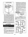
A WARNING
out-
NOTE - G32 senes units must not be used as a construction heater dunng any phase of construction. Very low re.
turn air temperatures,
harmful vapors and misplacement
of the filters will damage the unit and lower its efficiency.
The G32Q is an upflow gas furnace. A changeover kit
is necessary if the furnace is to be used with L.P. gas,
These instructions are intended as a general guide and
do not supersede Focal codes in any way. Consult authorities having jurisdiction before installation.
Shipping
and Packing List
1 - Assembled G32 furnace
1 - 3 inch x 2 inch vent transition piece (-100, -125
units only)
1 - Bag assembly containing:
1 - Electrical make-up box
I Insta!iatton'
Setttng Equipment
Select a location that allows for required clearances listed
on the unit rating plate. Also consider gas supply connections, electrical supply, vent connection and installation
and service clearances [24 inches (610 mm) at unit front].
The furnace must be level.
NOTE - 1/3 and 1/2 hp blower motors are equipped with
either four flexible mounting legs or three flexible legs and
one ngid leg. The ngid leg is equipped with a shipping bolt
and a flat white plastic washer (rather than the rubber
mounting grommet used with a flexible mounting leg).
This shipping bolt and flat washer must be removed before the furnace is put into operation. Once the sh_pping
bolt and washer are removed, the rigid leg will not touch
the blower housing.
_
CAUTION
.
WARNING
1 - Widng harness
1 - Snap bushing
2 - Filter clips
1 - Condensate
plug
1 - Condensate
drain adapter
1 - Brown accessory
wire
1 - Green ground wire
4 - Wire nuts
2 - Star washers
8 - Self-tapping
1 - Grounding
1 - Wire tie
I
and screws
screws
label
3 - Thread-forming
Shipping
[
screws
Damage
Check equipment for shipping damage. If you find any
damage, immediately contact the last carrier.
WARNING
WARNING
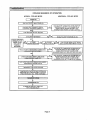
Return air can be brought in eitherside or at the bottomof
the unit.Scdbe linesshowthe outlineof each side and the
bottom return air opening.
Page 5
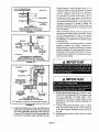
Bottom
Return
Air Applications
If return air is to terminate
Bottom
through the floor under the fur-
nace, a direct, airtight and sealed connection
made to the bottom of the furnace,
must be
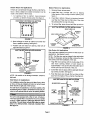
1 - Cut opening in floor or platform. Using knockouts
provided, cut bottom of base panel. See figure 2.
Return Air Applications
1 - Remove blower access panel.
2-
Install filter clips, provided with unit, by slipping
folded section of clip on edge of bottom opening. See
figure 4.
3 - Place filter in bottom of blower compartment beneath
rear filter clip. Press down on filter sides. Filter clips
flex allowing filter to snap into place.
KNOCKOUT PATTERN FOR BOTTOM
RETURN AIR APPLICATION
4 - To remove filter, press clip and pull filter up and out.
BOTTOM RETURN FILTER INSTALLATION
REAR
,v
vd
iV
Vd
_
SIDE _
2 - Bend a flange on return air plenum and lower into
floor or platform opening, See figure 3.
FURNACE
FURNACE
3 - Position unit over return air opening. Seal unit air
tight with return air plenum•
RETURN
R CLIP
URNACE
BACK
FIGURE 2
BOTTOM
FILT
FIGURE 4
Side Return Air Applications
AIR APPLICATION
Filter racks are available from Lennox for side return air
applications.See figures 5 and 6.
NOTE - The filter doormay be shipped in the rack behind
the filter./fnecessa_
remove the filter, retrieve the door
and continuewith the installationof the rack.
G32 UNIT
RETURN AIR
PLENUM
1 - Align filter rack opening with the inside edge of the
side return opening. Bottom of rack should be
approximately 1 inch(25 mm) from the bottom and 3
inches (76 mm) from the front of the unit.
PROPERLY
SIZED FLOOR
OPENING
2 - Screw filter rack intoplace with the eightselfddll,self
tap screws provided.See figure 5.
FIGURE
3
3 - Push filter door pins through the two holes in filter
door from the inside of the u-channel. See figure 6.
NOTE - Be cerefu/ not to damage insulation. Check for
tight seal,
SIDE RETURN
Side Return Air Applications
For installations where the return air is taken fl'oma retum
air drop, unitmay be installed with mtum air entl_ through
either the left or right side of the furnace.
For side returnair applications,cut furnace cabinetat the
dimensionsgiven on page 2. Embossedcomers are provided on bothcabinet sidesfor returnair opening location.
Page 6
INSTALLATION
in.(turn)
BLOWER DECK _=
RETURN
AIR
OPENING
i_ii_!'2'i:i:i_:"i:ii:i:i:;'i:
!:11:71:i:
7i:i:7!:;:i!:ii:ii;ii'i:ii
'i:_;:""_':
:<"_i:":i_i_ii,
ii_::i:!Ti:i;_;:7:%TiJ;:::tT;;
:::7:7
This unit is not equipped with a filteror rack. A field-provided high-velocityfilteris requiredfor the unit to operate
properly.A filter must be in place any time the unit is
operating. The unit does include filter clips for installation of a field-provided, internally installed filter.
See figure 4.
FILTER
12 in. (305) for
14 in. 13561 Filter
t8 In. (437) for
20 in, (508) Filter
RETURN AIR
PLENUM SIZE
12-314 In X 23-1/2 In (324 X
597) for 14 In (356) Filter
18-3/4 In. x 23-1/2 In,
(476 x 507)
for 20 In. 1508) Filter
1-13/t6
in.
cAa,NET
BASEI; .OM
,I
FIGURE 5
(34)
FILTER DOOR ASSEMBLY
FILTER DO0_
PIN
FILTER
DOOR
_
_T_
TAB
a gas appliance is operating in a room with negative pressure, the flue products can be pulled back down the vent
pipe and into the room. This reverse flow of the flue gas
may result in incomplete combustion and the formation of
carbon monoxide gas. This toxic gas might then be distributed through the house by the furnace duct system.
I I I _'l]l
FILTER
J
FIGURE 6
4 - Positionfilter door on end offilter so that the thumb
tab side of the filter door is away from the furnace.
Squeeze thumb tabs to secure filter to door.
5 - Guide filter and filter door into the filter rack installed
on side of furnace. Push door into filter rack until secure.
6 - To remove filter, pull filterdoor pins untildoor is released from filter rack,
Pipe & _tttings
S _¢ifi_ti_
:::% :::::: ::::::::::
Supply Air Plenum
Furnaces installed without a cooling coilrequire the installation of a removable access panel in the supply air ducL The
access panel should be large enough to permit inspection
(either by smoke or reflected light) of the heat exchanger for
leaks after installation. The furnace access panel must always be in placewhen the furnace is operating and it must
not allow leaks into the supply air duct system.
Return Air Plenum
See dimensionillustrationon page 2 for proper return air
duct size.
NOTE - For bottomreturn air, returnair ductshouldbe secured to the unit using rivets or Sqocks. For side return
air, secure return air duct to filterrack usingscrews. When
using screws, take care to avoid interference with the filter which may cause improper filtration.
The return air must not be drawn from a room where
another gas appliance (ie,, a water heater) is
installed. Even thoughthisfurnace draws its combustion
air from outside of the structure, other gas appliances that
share a utility room may not. When retum air is drawn
from a room, a negative pressure is created in the room. If
]
: ::
All pipe,fittings,primerand solventcementmust conform
with American NationalStandard Instituteand the American Society for Testingand Materials (ANSI/ASTM) standards. The solvent shall be free flowing and contain no
lumps, undissolved particles or any foreign matter that
adversely affects the joint strength or chemical resistance
of the cement. The cement shall show no gelation, stratification, or separation that cannot be removed by stining.
Refer to table 2 for approved piping and fitting materials.
TABLE 2
PIPING AND FITTINGS SPECIFICATIONS
PIPE & FITrlNG MATERIAL
Schedule 40 PVC (Pipe)
ASTM
SPECIFICATION
D1785
Schedule 40 PVC (Cellular Core Pipe)
Schedule 40 PVC (Fittings)
Schedule 40 CPVC (Pipe)
Use industry-approved standards to size and install the
supply and return air duct system. This will result in a quiet
and low-static system that has uniform air distribution.
:::
F89t
D2466
F441
Schedule 40 CPVC (Fittings)
F438
SDR-21 PVC (Pipe) or SDR-26 PVC (Pipe)
D2241
SDR-21 CPVC (Pipe) or SDR-26 CPVC (Pipe)
F442
Schedule 40 ABS (Pipe)
D1527
Schedule 40 ABS (Fittings)
D2468
ABS-DWV (Drain Waste & Vent)
(Pipe & Fittings)
D2661
PVC-DWV (Drain Waste & Vent Pipe & Fittings)
D2665
A
CAUTION
Primers and solvents must meet ASTM specifications,
PVC pdrnerisspecifiedin ASTM F 656. Use PVC solvent
cement as specified in ASTM D 2564 and ABS solvent
cement as specified in ASTM D 2235. Low temperature
solvent cement is recommended. Metal or plastic strapping may be used for vent pipe hangers.
Table 3 lists the available exhaust termination kits. All
Lennox vent terminations are PVC.
Page 7
TABLE 3
TERMINATION KITS
Lennox Part
No.
60G77
33K97
15F75
22G44
Kit LB#
LB-49107CE
LB-87942
LB-49107CC
LB-49107CD
15F74
LB_9107CB
44J41
LB-65678A
44J40
30G28
30G79
LB-65701A
WTK
WTKX
Description*Inches
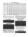
TABLE 4
VENT PIPE SIZING TABLE FOR G32Q FURNACES
MINIMUM DIAMETER OF INTAKE/EXHAUST
PIPE
(ram)
1-1/2" (38) Concentric
Termination Kit
3" (50,8) Low Pressure Drop
Concentric Term Kit
2" (50,8) Roof
Termination Kit
2" (50.8) Well
Assembly Termination
Kit
2" (50.8) Walt Ring Kit
Vent Pipe
Equivalent Length
Max. Feet (Meters)
G32-76
75,000
BTU
G32-100
100,000
BTU
G32-125
125.000
BTU
15 (4.57 m)
20 (6,10 m)
2"
2"
2'
2"
2"
3"
25 (7.62 m)
2"
2"
3"
30 (9.14 m)
2"
3"
3_
40 (12.19 m)
2"
3"
3"
50 (I 5.24 m)
2"
3"
3"
55 (16.76 m)
2"
3"
3"
60 (18,29 m)
3"
3"
3"
70 (21,34 rn)
3"
3"
3"
3" (76,2) Roof
Termination Kit
80 (24.38 m)
3"
3"
3"
90 (27.43 m)
3"
3"
3"
3" (76.2) Wall
Assembly TerminationKit
100 (30.48 m)
3"
3"
3"
110 (33,53 m)
3"
3"
3"
2" (50.8) Wall
Termination ExtendedVent
120 (36.58 m)
3"
3"
3"
130 (39.62 m)
3"
3"
--
NOTE - Min. pipeforG32-75 is 5 feet and 2 elbowsof 2 inchdmmeterp_pe.
NOTE - Min. pipe for G32-100 is 5 feet end 2 elbowsof 2 inch diameter
2" (50.6) Wall
Termination ExtensionRiser
pipe,
When making ABS joints, pieces can be prepared with a
cleaner. When joining ABS to PVC matedals, use PVC
solvent cement. Refer to this procedure as specified in
ASTM D3138.
Canada Only - In some provinces, PVC primer must be
purple in color, PVC solvent cement must be grey, ABS
solvent cement must be yellow and PVC solvent cement
used when joining ABS to PVC must be white.
[
l
:: ::,::.:_::: : :: ::.::..:
:.:::::::::: .::::::.:::::::::::::::::.:::::::::::::::: :;:. :::_:::::::::::::::::::::::::::::::::::::::::::::::::::::::::::::::::::::::::::::::::::::::::
::: :: :: ::.:]
Pipe used for exhaust and intake lines should be sized according to table 4. Note that maximum length of vent pipe
is for one run; either intake or exhaust. Maximum vent
length given is not the total length of intake plus exhaust
vents.
NOTE - Min. pipe for G32-125 is 5 feet and 2 e/bows of 2 inchdiameter
pipe.
For -100 and -125 kBtuh units, the intake connection is
sized for 3 inch diameter pipe. The exhaust connection
has a 2 inchnipple,A pipe transitionpiece is shippedwith
the unitto connectto 3 inchpipe. See figure 7 for 2 inch
and 3 inch venting applications.
Most venting applicationswill require 3 inch venting for
proper unitoperation.For no reason should the intake
and exhaust pipe be different diameter pipes. Regardless of the diameter of pipe used, the standard roof
and wail terminations described in Intake and Exhaust
Piping Terminations sectionshouldbe used.Exhaustpipingmust terminatewith 1-1/2 inchpipefor 1-1/2 inchor 2
inchventing and 2 inch pipe for 3 inch venting.
Each 90 ° elbow is equivalent to 5 feet (1.52 m) of vent
pipe. Two 45 ° elbows are equivalent to one 90° elbow.
One 45 ° elbow is equal to 2.5 feet (.76 m) of vent pipe.
G32-100 OR -125 WITH 2 IN. VENTING
2 IN. VEN_]
If intake and exhaust piping runs are not equal in length
and number of elbows, the larger diameter pipe must be
used for both runs.
NOTE - When a WTKX terminaUon kit (30G79) is
installed as part of the intake and exhaust piping, add
twelve feet to the equivalent length (the two 2 inch diameter 90° elbows end the 27 inch pipe in the kit).
For 75 kBtuh units, connections are provided for 2 inch
diameter venting which should satisfy most venting requirements. No transition pieces are provided or needed
for 2 inch venting.
3RIIENI_
X C2EI
N,
2IN.
I 3IN.
OUT
N
G32-100 OR -125 WITH 3 IN. VENTING
3 IN. VENT PiPE
NIPPLE
,..,
L_I
OUT
IN
FIGURE 7
Page 8
I
Iventingractl es
All cementing
specifications
of joints should be done according
outlined in ASTM D 2855.
The thickness of construction through which vent!air intake pipes may be installed is a minimum of 3 inches (76
mm) and a maximum of 24 inches (610 mm). If a G32 furnace replaces a furnace which was commonly vented
with another gas appliance, the size of the existing vent
pipe for that gas appliance must be checked. Without the
heat of the original furnace flue products, the existing vent
pipe is probably oversized for the single water heater or
other appliance. The vent should be checked for proper
draw with the remaining appliance,
Intake Piping
to the
1 - Measure and cut vent pipe to desired length.
2 - Debur and chamfer end of pipe, removing any ddges
or rough edges. If end is not chamfered, edge of pipe
may remove cement fTomfitting socket and result in
a leaking joint.
1 - Cement intakepipingin slip connectorlocated at top
of unit.
2 - Route pipingto outside of structure. Continue with
installationfollowing instructionsgiven in exhaust
and intake pipingterminationsection.
3 - Clean and dry surfaces to be joined.
WARNING
4 - Test fit joint and mark depth of fitting on outside of
pipe.
5 - Uniformly applyliberal coat of PVC primer for PVC or
ABS cleaner for ABS to inside socket surface of fitting and male end of pipe to depth of fitting socket.
6 - Promptly apply solvent cement to end of pipeand inside socket surface of fitting. Cement should be applied lightly but uniformly to inside of socket. Take
care to keep excess cement out of socket. Apply
second coat to end of pipe.
NOTE - Time is critical at this stage. Do not allow
pnmer to dry before applying cement.
7 - Immediately after applying last coat of cement to
pipe, and while both inside socketsurface and end of
pipe are wet with cement, forcefully insert end of pipe
into socket until it bottoms out. Turn pipe 1/4 turn during assembly (but not after pipe is fully inserted) to
distribute cement evenly.
NOTE - Assembly should be completed within 20
seconds after last application of cement. Hammer
blows should not be used when inse_ng pipe.
Exhaust Piping
1- Cemente_(haustpipthgintofluecollarsocketloceted
on the left side of the top cap.
8 - After assembly, wipe excess cement from pipe at
end of fitting socket.A properlymade jointwillshowa
bead around itsentire perimeter. Any gaps may indicate a defective assembly due to insufficientsolvent.
9 - Handle joints carefully until completely set.
2 - All horizontal runs of exhaust pipe must slope back
toward the unit. A minimum of 1/4 inch(6 ram) drop
for each 12 inches(305 mm) ofhorizontal runis mandatory fordrainage. Horizontal runs ofexhaust pip*
ing must be supported every 5 feet (1.52 m) using
hangers.
Page 9
5 - Test for spillage at the draft hood relief openingafter
5 minutes of main burner operation. Use the flame of
NOTE - Exhaust piping should be checked carefully
to make sure there are no sags or low spots.
match or candle, or smoke from a cigarette or cigar,
or a draft gauge.
NOTE - Exhaust piping must be Insulated wffh 1/2 inch
(13 ram) Armaflex or equivalent when nJn through unheated space. Do not leave any area of exhaust pipe
open to outside air. extenor exhaust must be insulated
wrth 1/2 inch (13 ram) Armaflex or equivalent.
{
Zl, CAUTION
I
6- After determining that each appliance remaining
connected to the common venting system properly
vents when tested as indicated in step 3, return
doors, windows, exhaust fans, fireplace dampers
and any other gas-burning appliance to their previous condition of use.
7 - If improper venting is observed dudng any of the
above tests, the common venting system must be
corrected. The common venting system shouldbe
resized to approach the minimum size as determined by using the appropriate tables in appendixG
in the current standards of the National Fuel Gas
Code ANSI Z223-1 in the USA, and the appropriate
Category 1 Natural Gas appliances venting sizing
tables in the current standard of the CAN/
CGA-B149.1 in the Natural Gas InstalLation Code in
Canada.
CAUTION
Removal of Unit from Common Venting System
In the event that an existing furnace is removed from a
venting system commonly run with separate gas appliances, the venting system may be too largeto property
vent the remaining attached appliances. The following
test should be conducted while all appliances (beth in operation and those not in operation) are connected to the
common venting system. If the venting system has been
installed improperly, corrections must be made as outlined in the previous section.
1 - Seal any unused openings in the common venting
system.
2 - Visually inspect the venting system for proper size
and horizontal pitchand determine there is no blockage or restdction,leakage, corrosionor other deficiencies which could cause an unsafe condition.
3 - To the extent that it is practical, close all building
doors and windows,and all doors between the space
in which the appliances remaining connected to the
common venting system are located and other
spaces of the building. Turn on clothes dryers and
any appliances not connected to the common venting system. Turn on any exhaust fans, such as range
hoods and bathroom exhausts, so they will operate
at maximum speed. Do not operate a summer exhaust fan. Close fireplace dampers.
4 - Follow the lightinginstructions. Place the appliance
being inspected in operation. Adjust thermostat so
appliance will operate continuously.
Intake and Exhaust Piping Terminations
Intake and exhaustpipesmay be routedeitherhorizontallythrough an outsidewall or verticallythroughthe roof.In
attic or closet instaUations,vertical termination through
the roof is preferred. Figures 8 through 20 show typical
terminations.
1 - Use recommended piping materials for both intake
and exhaust piping.
2 - Secure all joints, includingdrain leg, gas tightusing
approved cement.
3 - Pipingdiametersshouldbe determinedaccordingto
length of pipe run.See table 4. Locate intakepiping
upwind (prevailing wind) from exhaust piping. To
avoid recirculation of exhaust gas on roof terminations, end of exhaust pipe must be higher than intake
pipe.
Exhaust and intake exits must be in same pressure
zone. Do not exit one through the roof and one on the
side. Also, do not exit the intake on one side and the
exhaust on another side of the house or structure.
4 - intake and exhaust pipes should be placed as close
together as possible at termination end (refer to illustrations). Maximum separation is 3 inches (76
ram) on roof terminations and 6 inches (152 ram)on
sidewall terminations.
5 - Exhaust piping must terminate straightout or up as
shown, tn rooftopapplications,a 2 inchX 1-1/2 inch
reducer for 2 inch venting,3 inch x 2 inch reducerfor
3 inch venting must be used on the exhaust piping at
the point where it exits the structure to improve the
velocity of exhaust away from the intake piping.
Page 10
On roof terminations, the intake piping should terminate straight down using two 90 ° elbows. See figure 8.
EXHAUST
12 (305) ABOVE
AVERAGE
SNOW
ACCUMULATION
INTAKE
TERMINATION
NOTE - If winter design temperature is below 32°F (O°C),
exhaust piping must be insulated with 1/2 inch (13 mm)
Armaflex
or equivalent
when run through unheated
space. Do not leave any surface area of exhaust pipe
open to outside air," exterior exhaust pipe must be insulated with 1/2 inch (13 ram) Armaflex or equivalent. In extreme cold climate areas, 3/4 inch (19 mm) Armaflex or
equivalent is recommended.
Insulation on outside runs of
exhaust pipe must be painted or wrapped to protect insulation from deterioration.
Inches (mm)
EXHAUST
CONCENTRIC ROOFTOP TERMINATION
(60G77) LB-49107CE for G32-75 Units Only
(33K97) LB-87942 for G32-100 & -125 Units Only
FIGURE 9
NOTE - During extremely
cold temperatures,
below
approximately 20°F (6.67°C), units with long runs of vent
pipe through unconditioned space, even when insulated,
may form ice in the exhaust termination that prevents the
unit from operating properly. Longer run times of at least 5
minutes will alleviate most icing problems. Also, a heating
cable may be installed on exhaust piping and termination
to prevent freeze-ups. Heating cable installation kit is
available from Lennox. See Condensate Piping section
for part numbers.
NOTE - Care must be taken to avoid recirculation of exhaust back into intake pipe.
6 - On field-supplied terminations
1/2 (13) ARMAFLEX
INSULATION IN
UNCONDITIONED SPACE
2 X 1-1/2
(51 X 38)
REDUCER
_ _
1/2 (13) ARMAFLEX
INSULATION
t'
I
_
'VC
6 (I 52)
MAXIMUM
2 (_ I PVC
for side wall exits, exOUTSIDE
WALL
Inches (ram)
(15J74)
IMAX.
(ram)
3 x 2 (70 x 51) OR
2 x %1/2 (51 x 38)
PVC REDUCER
1/2 (13) FOAM
INSULATION IN
UNCONDrrlONED
SPACE
12 (305) ABOVE
ACCUMULATION
AVERAGE SNOW
3 (76) OR
2 (5t) PVC
UNCONDmONED
ATTIC SPACE
PROVIDE SUPPORT
FOR INTAKE AND
F.XHAUST LINES
ROOFTERMINATION KIT
(15F'75)LB-49107CCfor 2 (5t) Venting
(44341)LB-65678Afor 3 (76)Venting
FIGURE
12 (305) MIN.
PV
haust piping should extend a maximum of 12 inches
(305 mm) beyond the outside wall. Intake piping
should be as short as possible. See figure 10.
Inches
INTAKE
j
PLING
TOPVIEW
WALLRINGKIT
LB-49107CB
for2 (50,8 ! Venting
FIGURE 10
On field-supplied terminations, a minimum separation distance between the end of the exhaust pipe
and the end of the intake pipe is 8 inches (203 mm).
8- If intake and exhaust piping must be run up a side
wall to position above snow accumulation or other
obstructions, the piping must be supported every 3
feet (.91 m) as shown in figure 15. Refer to figures 13
and 14 for proper piping method. W'FK wall termination kit must be extended for use in this application,
See figure 18 or use kit WTKX shown in figure 19.
When exhaust and intake piping must be run up an
outside wall, the exhaust piping is reduced to 1-1/2
inches (38 mm) after the final elbow. The intake piping may be equipped with a 90 ° elbow turndown. Using 90 ° turndown will add 5 feet (1.5 m) to the equivalent length of the pipe.
7-
8
Page 11
1/2 (12.7) FOAM INSULATION
IN UNCONDITIONED SPACE
courtyard areas or other recessed areas. Do not
position termination ends directly below roof eaves
or above a walkway. Since the G32 is a certified direct vent, Category iV gas furnace, the location of
the termination is limited by local building codes. In
the absence of local codes, refer to the current National Fuel Gas Code ANSI Z223-1 in USA, and current standard CAN/CGA-B149.1
of the Natural Gas
Installation Instructions in Canada for details. The
Inches (mm)
n
OUTSIDEWALL
qlp
Optional
Turndown
Shown
(Intake Onty)
TOPVIEW
WALL TERMINATION
(22G44)LB-49107CDfor 2 (50,8)Venting
(44J40)LB-65701Afor 3 (76.2)Venting
termination should be at least 12 inches (305 mm)
from any opening through which flue products could
enter the building.
FIGURE 11
When horizontally vented, minimum clearance for
termination from electric meters, gas meters, regulators and relief equipment is 4 feet (1.2 m) for US
installations. Refer to the current CAN/CGA-B149.1
EXHAUST
TERMINATION
for installations in Canada or with authorities
local jurisdiction.
EXHAUST
having
At vent termination, care must be taken to maintain
protective coatings over building materials (prolonged exposure to exhaust condensate can destroy
protective coatings). It is recommended that the exhaust outlet not be located within 6 feet (1.8 m) of a
condensing unit because the condensate can dam-
INTAKE
abovegrade,
Inches (ram)
age the painted coating.
CONCENTRIC WALL TERMINATION
(60G77) LB-49107CE for G32-75 Units Only
(331(97) LB-87942 for G32-t00 & -125 Units Only
FIGURE 12
12 (305) MIN for 2 (51)
Inches(mm)
20 (5oa)MAXfor3 (76):
F
UNCONDITIONED
SPACE
OUTSIDE WALL
PROVIDE SUPPORT
FOR INTAKE AND
/
EXHAUST UNES EVERY
HI II
t2(S_0)ASOVE
3_(914)
1/2113) FOAM
INSULATION IN
UNCONOmONED
SPACE
Ii2 (131 FOAM
INSULATION
SiDE VIEW
WALL RINGTERMINATION
(15F74)LE-49107CBfor 2 In. (51)Venting
See v.ntlng
table 4 for maglng_
venting
lengths
with this Irmr:l_mant.
FIGURE 13
9 - Position terminationends so they are free from any
obstructions and above the level of snow accumulation (where applicable). Termination ends must be a
minimum of 12 inches (305 mm) above grade level.
Do not point into window wells, stairwells, alcoves,
10 - Suspend piping using hangers at a minimum of every
5 feet (1.52 m) for schedule 40 PVC and every 3 feet
(.91 m) for ABS-DWV, PVC-DWV, SDR-21 PVC,
and SDR-26 PVC piping. A suitable hanger can be
fabricated by using metal or plastic strapping or a
large wire tie.
11 - In areas where piping penetrates joists or interior
walls, hole must be large enough to allow clearance
on all sides of pipe as it passes through the center of
the hole.
12 - Isolate piping at the point where it exits the outside
wall or roof.
Page 12
Inches(turn)
1/2 (13)
FOAM
INSULATION
Front View EXHAUST
3 x 2 {76 x 51) OR
2 x 1.t/2 (61 x 36)
REDUCER BUSHING LOCATION
3 (76) OR
2 (51) 90 _ ELBOW
12
FOR OFFSET TERMINATION
18M
i
Optional Turndown
(Not Shown)
May Be Used on
Intake Only
_
3 (76) OR
2 (5t) 90" ELBOW
_
Side View_
Inches (ram)
FRONT VIEW
WALL TERMINATION
(22G44) LB-49107CD
for 2(51) Venting
(44J40) LB-65701A
for 3(76) Venting
FIGURE
EXHAUST VENT
•
INTAKE
VENT
OPTIONAL VENT TERMINATION FOR
MULTIPLE UNIT INSTALLATION
WALL TERMINATION KIT WTK
14
FIGURE 17
METALOR PLASTIC
STRAPPING
Front
COVER EXHAUST
VENT WITH
1/2 (13)
FOAM
INSULATION
IZ
(3os)
View
INTAKE
AIR
FIGURE
13 - When
furnace
is installed
15
5
in a residence
where
unit is
down for an extended
period of time, such
vacation home, make provisions for draining
densate
collection
trap and lines.
shut
14 - Based
a
on the
recommendation
multiplefurnace
to four
horizontally,
kits
as shown
Front View
in
_,_,
t 2 MIN
(30_)
1127)..L
Above Grade
as a
con-
GRADE
of the manufacturer,
installation
termination
EXHAUST
AIR
may use a group
WTK
assembled
figure
of up
together
////
17.
_--T_--
(('-_-_-_"
//
"_'l/EXHAUST
INTAKE
AIR
VENT
/
EXHAARUS
_
/
/ /
//,ii
@1
----n
812031
I_=_,,,I,,,=_l
II
SideView
II
Inches (ram)
r'--r
lJil,
/ /
1/2 (13) Foam
Insulation in
Unconditioned _ace
Mn}mum
Side View
/ /
ABO'_GPJmE
, GRADE
F
VENT TERMINATIONS
MODEL WTK WALL TERMINATION KIT (30G28)
EXTENDED VENT FOR GRADE CLEARANCE
EXHAUST VEN_
FIGURE 18
INTAKE VENT
Inches (mm)
L_
OUTSIDE WALL
VENT TERMINATIONS
WALL TERMINATION KIT 130G28) WTK
FIGURE t6
Page 13
freezing of the condensate, which would block the drainline. Use an electric heat cable if you route the condensate line through unconditioned areas.
9
Inches (mm)
[
Front View
I '10"
_, EXHAUST
= _
INTAKE
NOTE - Enclosed ex_us_ pipe _s
insuleted w;th _F2 i,_Ch(13 ram)
foam insu_abon If in_al(ear_ ex-
VENT
hsusl I_pes am reversed, sl=land
34
VENT
r_move
foam
vent mr=st be
instJlat_ot_
A
insulated
1 - Determine
Ii
CAUTION
and
which side condensate
will exit the unit.
teat)ply to OUmr vent Exhaust
2-
4
Side View
USTVENT
Connect 1/2 inch (13 mm) plastic pipe plug (provided) in the unused end of the condensate trap.
Install plug so that it is sealed water tight yet able to
be removed. Do not permanently seal the connection. Teflon tape is recommended to seal joint. See
figure 21.
CONDENSATE
ASSEMBLY
(For left or rightinstallation)
o
iNTAKE
VENT
COMBUSTION AIR
INDUCER BRACKET
COLD
HEADER
BOX
E
ADAPTER
VENT TERMINATIONS
MODEL WTKX (30GT9)
EXTENSION RISER FOR GRADE CLEARANCE
ELBOW
FIGURE 19
G32Q VENTING
IN EXISTING
CONDENSATE TRAP
NIPPLE
ADAPTER
CHIMNEY
BOOTORCAP
FIGURE 2t
3 - Use the provided condensate drain adapter (3/4" x
1/2") and a field-providednipple to carry drainage
outside the cabinet. If a fieldsubstitute is needed, 1/2
inch CPVC x 1/2 inch MPT adapter and 1/2 inch
CPVC is acceptable for use.
NOTE - Do not dischal_e exhaust gases dit ently into
or vent stack.
II ventCal discharge through at, ex_6ng unused chimney or stack ts require<J,
i_sertpipingintgde chlm,'.eyurdilthe pipe open end Is above top of _y
and
termimlte as iltusttstad. I. any extedor po(tlon of ¢ilrmney, the exhaust vent must
be insulated.An alternatemethodis to flit the chimneywith vetrmc.ulitoor equal
to take advantage
of its acoustic and thermal properties,
FIGURE 20
Condensate
Piping
This unit is designed for either right- or left-side exit of
condensate piping. Route the condensate drainiine only
within the conditioned space: this prevents possible
4 - Glue nipple to the adapter using the procedures outlined in the "Joint Cementing Procedures" section.
The nipple/adapter assembly should be connected
in a non-permanentmanner and must be water tight.
Teflon tape is recommended to seal the joint.
For Right-Hand Side Condensate Exit:
Install the nipple/adapter assembly from the outside of the cabinet and insert the adapter intothe
threaded opening in the condensate trap.
For Left-Hand Side Condensate Exit:
Insert nipple/adapterassembly from the left hand
side of the cabinet and through the combustion air
inducer mounting structure into the threaded
opening in the condensate trap.
5 - Connect field-supplied plumbing to nipple and route
to open drain. Plumbing should be vented to a point
higher than the condensing coil. See figure 22.
Page14
3 - The gas piping must not run in or through air ducts,
clothes chutes, gas vents or chimneys, dumb waiters or elevator shafts. Center gas line through piping
hole. Gas line should not touch side of unit. When
left-hand gas plumbing is required, gas line should
be installed in the lower half of knockout so that piping will clear combustion air inducer. See figure 24.
4 - The piping should be sloped 1/4 inch (6.4 mm) per 15
feet (4.57 m) upward toward the meter from the furnace. The piping must be supported at properintervals [every 8 to 10 feet (2.44 to 3.01 m) using suitable
hangers or straps. A drip leg should be installed in
vertical pipe runs to the unit.
5 - Some local codes may require installationof a manual main shut-off valve and union (furnished by the installer) external to the unit. Union must be of the
groundjoint type,
CONDENSATE PLUMBING
(Plumbing must be vented higher than coll.)
II
FIGURE
22
6- Connect condensate drain line (1/2 inch [13 mm]
SDR 11 plastic pipe or tubing) to condensate connection on condensate trap assembly and route to
open drain. Condensate line must be sloped downward away from drip leg to drain. If the drain level is
above condensate outlet, use a condensate pump to
pump the condensate to the higher level. Condensate drain line should be routed within the conditioned space to avoid freezing of condensate and
blockage of drain line. If this is not possible, a heat
cable kit may be used on the condensate line. Heating cable kit is available from Lennox in various
lengths; 6 feet (1.8 m) - kit no. 18K48; 24 feet (7.3 m)
- kit no. 18K49; and 50 feet (15.2 m) - kit no. 18K50.
CAP-_D-I_I
U
FIGURE 23
NOTE - Install a 1/8 inch NPTplugged tap in the field pip
ing upstream ofthe gas supplyconnection to the unit. The
tap must be accessible for test gauge connection. See
figure 24.
LEFT SIDE PIPING
MANUAL MAIN
SHUT-OFF
VALVE
1/8 in. NPT
PLUGGED
TAP
GAS VALVE
....
--I, RIGHT SIDE PIPING
_(.=.__
_=.-,_t_
(STANDARD)
1 - Gas piping may be muted into the unitthrough either
the left- or right-hand side. Supply piping enters into
the gas valve from the bottom of the valve as shown
in figure 24.
2- When connecting the gas supply, factors such as
length of run, number of fittings and furnace rating
must be considered to avoid excessive pressure
drop. Table 5 lists recommended pipe sizes for typical applications.
NOTE - Use two wrenches when connecting gas piping to avoid transferring torque to the manifold.
Page 15
118In. NPT
PLUGGED
..........................
j,AP
GAS VALVE
FIGURE 24
TABLE 5
GAS PIPE CAPACITY
Nominal
Iron Pipe Size
-InchesImm)
NOTE
- ft.3/hr Im31hrl
Internal
Length
of Pipe-Feet
(m)
Diameter
.InchesImm)
10
(3.048)
20
(6.096)
30
(9.144)
40
(12.192)
50
115.2401
60
(18.288)
t/4
(635)
364
(9 246)
43
(1 13)
29
(.82)
24
(68)
29
(.57)
18
(81)
18
(45)
15
( 401
14
(40}
19
(3?)
12
(.34)
3/8
(6,53)
493
(12.5221
95
(269)
65
(1.84)
52
(1 47)
45
(127)
40
(113)
36
(1.02)
33
(73)
31
(88)
29
(.82)
27
(75)
(127)
622
(17.799)
175
(496)
120
(340)
97
(2.75)
82
(232)
73
(2.07)
66
(1.87)
61
(173)
57
(101)
53
(1.50)
50
(142)
314
(19.05)
.824
(20.930)
360
(10.19)
250
{706)
200
(566)
176
(4.81)
161
(4.28)
138
(3.91)
125
(3 54)
118
(3.34)
110
(3 11)
103
(292)
1
(254)
1 049
(26.645)
680
(19,25)
468
(13.17)
379
(10,62)
320
(9,06)
288
(807)
260
(7.36)
240
(6 90)
220
(6.23)
208
(580)
!95
(6.62)
1-1/4
(31.75)
1.380
(35.052)
1400
(39.64)
960
(26.90)
770
(21.80)
660
(18,69)
580
(1642)
630
(15.01)
490
(13.67)
460
(13.031
430
(1218)
400
(11.33)
Io1/2
(381)
1.610
(40.894)
21 O0
(59.46)
466
(41.34)
1180
(3341)
990
(2803)
900
(2548)
810
(22.94)
750
(2124)
690
(19.54)
650
(1841)
620
(17,56)
2
(5O.8)
2.0_7
(52.502)
3950
(111.85)
2750
(77,87)
2200
(62.30)
1906
(5380)
1680
(47.57)
1520
(43.041
1400
(3964)
1300
(36.81)
1220
(34.58)
1150
(32.56)
2-112
(83.5)
2469
(67 713)
6300
(17839)
4350
(12317)
9520
(9967)
3000
(84.95)
2650
(75.04)
2400
(67.96)
2250
(63.71)
2050
(58,05)
1950
(55.22)
1880
(52.38)
3
(76.2)
3068
(77.927)
11000
(31148)
7700
(218.03)
6250
(17698)
5300
(150.07)
4750
(134.50)
4300
(121,76)
3900
(110.43)
3700
(104.77)
3450
(97,69)
3250
(92.03)
4
(101.6)
4 026
(102.260)
23000
(651.27)
15800
(447.39)
12800
(362 44)
10900
(308.64)
9700
(274.67)
8800
(249.t8)
St00
(229.99)
7500
(212.37)
7200
(203.88)
6700
(189.72)
- Capacity
j 'iven in cubsc feet (m 3) o f gas per hour and based
on O.60 specific gravity
Leak Check
After gas piping is completed, carefully check all piping
connections (factory- and field-installed)
for gas leaks.
Use a leak detecting solution or other preferred means.
70
(21.336)
80
(24.384)
90
(27.432
100
(30.480)
gas.
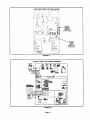
Figu re 28 shows thermostat designations for identification purposes. Refer to figure 29 for control box arra ngement, figure 30 for a detail of the Surelight _integrated
control, figure 32 for point-to-point
33 for schematic wiring diagram
field wiring and figure
and troubleshooting,
ELECTROSTATIC DISCHARGE (ESD)
Precautions
CAUTION
A, IMPORTANT
and Procedures
1
1 - Install field make-up box on either side, inside orout
of the cabinet. Knockouts are provided in box and
cabinet to run wiring. See figures 26 and 27.
2 - Remove cap from knockout in blower deck on the
same side as the installed make-up box.
iii::i::
i.................
j
A field make-up box is provided for line voltage wiring.
Line voltage wiring to unit is done through the J69 jack
from the field make-up
box to plug P69 from the control
box. See figures 26 and 27 for make-up box installation.
Page 16
A IMPORTANT
3-
Electrically ground unit in accordance with local
codes or, in the absence of local codes, in accordance with the current National Electric Code (ANSI/
NFPA No. 70) and in Canada with the current Canadian Electric Code part 1 (CSA standard C22.1). The
ground wire is provided in the field make-up box.
EXTERIOR MAKE-UP BOX INSTALLATION
BUSHING
To ensure proper grounding of the furnace, two star
washers are included in the electrical make-up box
bag assembly. Place the star washer on secudng
screw before installing the make-up box. Make sure
the star washer breaks the paint on the cabinet so
that the washer is touching metal. Unit is not properly
grounded if paint has not been removed by star
washer.
4-
J69
(Shown with
accesso_
wire connec_d)
P69 from
ControlBox
An optional 120 volt accessory wira is provided with
G32 units. Install the brown accessory wire into J69
FIGURE 27
jack plug by inserting the pin of the brown wire into
the open socket of the
jack. See figure 25. Any
accessory rated up to 4
amps can be connected to
this wire. Connect the
neutral leg of the accessory to the neutral white wire
in the make-up box. The
accessory terminal is energized whenever the
blower is in operation.
G32Q and CONDENSING UNIT
THERMOSTAT DESIGNATIONS
INSYALUNG BROWN
ACCESSORY WIRE TO J69
(Refer to specific thermostat and outdoor unit,)
G32 $UREUGHT
BROWN
Two-Stage
Condensing
Thermostat*/
COkq'ROL
BOARD_
/
® ....
NEUTRAL
J_J=l
®_
FIGURE 25
5 - Insert the three-pin (P69)
plug from the control box
into the knockout provided in the blower deck.
B_s most
co.Mo.A ,so,,T
it don
and Wl terminal
6 - Connect jack (J69) from make-up box to jack plug in
blower deck.
7 - Select wire size according to the blower motor amps.
8 - Snaphole bushing is provided for the widng entry
hole in the cabinet. A snaphole plug is providedto
seal the unused wire entry hole
OMPRESSC_
G32"rwo_AGE
CONTROL
@
"$1ngll-_tlge
_ H,sUN,T
....
COMPRESSQR
(_ J_ -°_"_L°_-_ .(-_
BLAC
WNIT_
_
.......
_G
_nit
not contain
is designated
W2 tmrmlnal
as W.
FIGURE 28
9- Install room thermostat according to instructions
provided with thermostat. See figure 28 for thermostat designations. If furnace is being used with heat
pump refer to FM21 installation instruction.
NOTE - W2 thermostat connection (pigtail) must be
made at two-speed control board. SureLight TM board
is not equipped with a W2 terminal
INTERIOR MAKE-UP BOX INSTALLATION
10 - Install a separate disconnect switch near the unit so
power can be turned off for servicing.
11 - Complete wiring connections to equipment using
wiring diagrams provided with unit and in figures 32
and 33. Use 18-gauge wire or larger for thermostat
connections.
__._
/
FIGURE 26
J69
12 - The two-stage relay board controls first- and secondstage furnace operation providing maximum comfort
and efficiency. The furnace may be controlled by either a single- or two-stage room thermostat.
13 - The blower will run on continuous fan speed with the
low speed tap connected to the (ACB LOW) 120 volt
terminal and the thermostat set to "FAN ON" when
there is no call for heating or cooling.
Page 17
G32Q CONTROL
BOX
DOOR
INTERLOCK
SWITCH
._,_
C=RCU_
TRANSFORMER
'_1_ _BREA_ER
SURELIGHT
CONTROL
/
TWO_TAGE
BOARD
_'--'-CONTROL
_
FIGURE 29
SURELIGHT INTEGRATED CONTROL BOARD
"_-III
IIZ
II
LO_
0110
TX
HOT :_(_
UIIO
,_
I
-÷
_.._, ..
_
÷
L_____J
FANDELAY
o.P
_
SFJ_-_E
TERMINAL DESIGNATION_
Blower - Coollr_ Bleed {Line Volt)
Blower- Heatina SPeed (Line Volt)
AJtemateBlower SPeeds (Dead}
ContinuousLow Speed Blower
AccessoryTerminal (Line VoW4amp max.)
120VAC Hot to Transformer
120VAC Hot Input
Heat Only Accessory (Line VoltI
120VAC Neutrals
24VAC Hot from Transformer
ACBCOOL
ACB HEAT
PARK
ACB LOW
ACC
TX
HOT
HTG ACC
NEUTRALS
24VAC HOT
24VAC RTN
FLAME SENSE
JI
24VAC Return from Transformer (Common)
Flame Sense Terminal
-I
I
I
...........
_.__
i
I
I
I
J
J
_--.-J
®
LOW VOLTAGE
®
Y
G W R C
Y
Q W R
/
TERMINAL
CONN ECTJON TO THERMOSTAT
* FACTORY SET AT SOSECONDS
C
FIGURE 30
Page 18
G32Q TWO-STAGE
CONTROL
BOARD
MODE OF
OPERATION
JUMPER
(Factory set
at TWO STAGE)
W2 TIMED
ON DELAY
JUMPER
(Factoryset
at 8 minutes.)
0
FIGURE 31
TYPICAL G32Q FIELD WIRING DIAGRAM
FIGURE 32
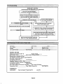
Page 19
TYPICAL
G32Q SCHEMATIC
F20M /_C
4.5 E]_(4
I|F IJ_D]
,,o
HION NEAT
O
srj Ti_
SlO
Ul_
Ll'_b_m
LIMIT
SI]_
c_urr
l_
AiR Lml_
W_
r---n 2
II
I
it
i
IIilll
I
I I
I i
WIRING
I
i
--_'
(ill
FIGURE 33
Page 20
IVI
DIAGRAM
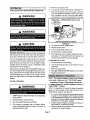
5 - Remove unit access panel.
FOR YOUR SAFETY
READ BEFORE
6 - Turn gas valve knob to OFF position. See figure 34.
OPERATING
7 - Wait five (5) minutes to clear out any gas. If you then
smell gas, STOP! Immediately call your gas supplier
from a neighbor's phone. Follow the gas supplier's
instructions. If you do not smell gas go to next step.
WARNING
HONEYWELL VR8205 SERIES GAS VALVE
HIGH
FIRE
ADJUSTING SCREW
(under
cap)
MANIFOLD
PRESSURE
TAP
LOW FIRE
ADJUSTING SCREW
(under cap)
INLET PRESSURE
TAP
GAS VALVE SHOWN IN OFF POSITION
CAUTION
FIGURE 34
8 - Turn gas valve knob to ON position,
9 - Replace access panel.
10 - Turn on all electrical power to unit,
BEFORE OPERATING smell all around the appliance
area for gas. Be sure to smell next to the floor because
some gas is heavier than air and will settle on the floor.
This unit is equipped with a gas control knob. Use only
your hand to turnthe gas controlknob. Never use tools. If
knob will not turn by hand, do not try to repair it. Call a
qualified service technician. Force or attempted repair
may result in a fire or explosion.
G3Q2 unitsare equippedwith a SureLighFMignitionsystem. Do not attemptto manually lightburnerson this furnace. Each time the thermostatcallsfor heal the burners
will automaticallylight.The ignitordoes not get hot when
there is no call for heat on units with SureLighF= ignition
system.
Gas Valve Operation
11 - Set thermostat to desired setting,
12 - If the appliance will not operate, follow the instructions given in "Turning Off Gas To Unit" section and
call your service technician or gas supplier.
Turning Off Gas To Unit
1 - Set thermostatto lowest setting,
2 - Turn off all electrice]powerto unit if service is to be
performed.
3 - Remove access panel.
4 - Turn gas valve knob to OFF position, Do not force.
5 - Replace access panel.
NOTE - The thermostatselec_on jumper on the two-stage
control board is factory-setin the "TWO-STAGE"_,
Applications Using A Single, Stage Thermostat
A * Heating Sequence - Mode of Operation Jumper in
"ONE-STAGE" Position
WARNING
NOTE - To operate in this mode, the mode of operation
jumper on the two-stage control board must be in the
"ONE S TAGE" position. See figure 31,
1 - STOPf Read the safety informationat the beginning
of this section.
2 - Set thermostat to lowest setting,
3 - Turn off all electrical power to furnace,
4- This furnace is equipped with an ignition device
which automatically lights the burner, Do not try to
light the burner by hand.
1 - On a call for heat, thermostat contacts close sending
a signal to the integrated control module. Module
runs self-diagnostic program and checks high limit
switches for normally dosed contacts and pressure
switches for normally open contacts.
2 - Control module energizes combustion air inducer at
high speed for 15-second prepurge.
3 - Control module checks pressure switches and high
limit switch for closed contacts.
Page 21
4-
After the prepurge is complete and the pressure
switch is closed, a 20-second initial ignitor warm-up
period begins.
5 - After warm-up period, gas valve is energized on second stage (high heat).
6 - Gas valve opens and gas is ignited. When flame is
established,
flame sensor sends signal to control
module to de-energize the ignitor.
NOTE - If the flame is not detected after the first ignition attempt, the control module de-energizes the
gas valve and the prepurge / ignition sequence is repeated. After five ignition trials without proof of
flame, the unit will go into a Watchguard / Flame Failure mode. In Watchguard mode, control will repeat
the prepurge and ignition trial sequence after 60 minutes of unsatisfied thermostat demand.
7 - After flame is sensed, 45-second FAN ON delay begins. Indoor blower is energized on high heating
speed after delay. ACC and HTG ACC terminals are
energized.
8 - When heat demand is satisfied, gas valve is de-energized, combustion air inducer goes to 5-second
postpurge and adjustable FAN OFF delay begins.
B - Heating Sequence - Mode of Operation Jumper in
"W2 TIMED" Position
NOTE - To operate in this mode, the mode of operation
jumper on the two-stage control board must be in the "W2
TIMED" position. See figure 31.
1 - On call for heat from a single-stage thermostat,
operation sequence followssteps 1 through4 as outlined above in single-stageheating sequence.
2 - Gas valveisenergizedon low heat(firststage). Ignition
occursand signal is sentfrom control moduleto twostage controlboard to begin "W2 ON" delay (factory
set at 8 minutes).See figure 31 for delay settings.
3 - "FAN ON" delay begins. When delay ends, indoor
blower motor is energized on low speed.
4 - If the selected "W2 ON" delay ends and the demand
for heat is still not satisfied, the two-stage control
switches the furnace to secondstage operation(high
heat). In second stage operation, the following occur: combustion air inducer motor is energized at
high speed; indoorblowermotoris energizedon high
heating speed; and gas valve is energized on high
heat after an 8-second delay.
5 - When the demand for heat is satisfied, the high- and
low-heat gas valves are de-energized, the combustion air inducer goes into the 5-second post purge op
oration on low speed and the indoor blower motor
goes into the FAN OFF delay on low speed.
Applications
Using
A Two-Stage
Thermostat
C - Heating Sequence - Mode of Operation Jumper in
"13NO-STAGE"
Position (Factory Setting)
The sequence of operation is the same as outlined above
(in section B), except that low-heat and high-heat operation is controlled from the room thermostat.
1 - When the thermostat is set to "FAN ON," the indoor
blower will run on continuous fan speed when there is
no cooling or heating demand.
2 - When the G32 is running in the low heat (first stage)
mode, the indoor blower wilt run on continuous fan
speed.
3 - When the G32Q is running in the high heat (second
stage) mode, the indoor blower will run on the heating speed.
4 - When there is a cooling demand, the indoor blower
will run on the cooling speed.
Gas Flow
To checkfor propergas flowto the combustionchamber.
determine the Btu (kW) inputfrom theunitratingplate.Divide this inputrating by the Btu (kW) per cubicfoot (cubic
meter) of availablegas. The resultis the requirednumber
of cubicfeet (cubicmeter) per hour.Determinethe flow of
gas throughthe gas meterfor two minutesand multiplyby
30 to get the houdy flow of gas.
Gas Pressure
1 - Check gas line pressurewith unitfiringat maximum
rate. A minimumof 4.5 in. w.c. (1.12 kPa) for natural
gas should be maintained.
2 - After line pressure has been checked and adjusted,
check high heat regulatorpressure.See figure34 for
gas pressure adjustment screw location. High heat
manifoldpressure is given in table 6.
Page 22
TABLE
6
Manifold Pressure (outlet) in. w.g (kPa)
Model No.
0 to 4500 ft. (0 to 1372 m)
above sea level
4501 to 5500 ft.
(1373 to 1676 m)
above sea level
5501 to 6500 ft.
(1677 to 1981 m)
above sea level
6501 to 7500ft,
(1982to2286 m)
above sea level
3.8
3,5
35
3.5
3.3 (0.82)
3.2 (0.80)
G32-75 natura_
G32-100 natural
3.5 (0.87)
G32-125 natural
34(0.85)
7.5
7.5
7.5
7.5
G32-100 L,P.
7.5 (1.90)
7.3 (1.81)
7.1 (1.80)
7.0 (1.74)
G32-125 L,P.
7.5 11.90)
7.3 (1.81 }
7.1 (1.8o)
7.0 (1.74)
G32-75 L.P
NOTE - Shut unit off and remove manometer as soon as
an accurate reading has been obtained. Take care to replace pressure tap plug.
NOTE - During this test procedure, the unit will be overt/ring:
Manifold Pressure Measurement & Adjustment
NOTE
- Pressure
from Lennox
ment.
test adaptor
to facilitate
kit (10L34)
manifold
pressure
is available
measure-
1 - Connect test gauge to outlet tap on gas valve.
2 - Disconnect pressure sensing hose from gas valve
and plug hose by covering opening with tape or
equivalent. Leave barbed fitting on valve open to atmosphere. See figure 35 for differential pressure
switch circuitry on 75 kBtuh models. Only 75 kBtuh
models are equipped with a secondpressure switch.
Other models have single pressure switch.
• Operate unit only long enough to obtain accurate reading to prevent overheating heat exchanger.
• Attempts to clock gas valve during this procedure will
be inaccurate. Measure gas flow rate only during normal unit operation.
6 - When test is complete remove obstruction from hose
and return hose to gas valve barbed fitting.
75 kBtuhDIFFERENTIALPRESSURESWITCHCIRCUITRY
Refer to table 6 for manifold pressuresettings for installations at altitudes from 0 to 7500 feet (0 to 2286 m).
NOTE - In Canada, certification for installations at elevations over 4500 feet (1372 m) is thejurisdiction of local authorities.
BURNER
BOX
LOW HEAT
DIFFERENTIAL
PRESSURE
BARS
SWITCH
SOX
SENSING
HOSE
TEE
HIGH HEAT
DIFFERENTIAL
PRESSURE
SWITCH
The two pressure switches (high and low heat) are factory
set and are not to be adjusted.
GAS
VALVE
SENSING
HOSE
COMBUSllON
AIR PRESSURE
SENSING HOSE
NOTE - Disconnect power to unit before making any
adjustments.
GAS
VALVE
COMBUSTION
AIR INOUCER
HONEYWELL PPS
PRESSURE
SWITCH
SHOWN
PRESSURE
SWITCH
SENSING
HOSE
LEFT SIO_ OF PRESSURE SWITCH = MORE NEGATIVE
RIGH'r SIDE OF PRESSURE SWITCH = LESS NEGATIVE (Closer to Zero)
FIGURE 35
3 - Start uniton high heat and allow 5 minutes for unitto
reach steady state.
4- While waiting for the unit to stabilize, notice the
flame. Flame should be stable and should not lift
from burner. Natural gas shouldbum blue.
5 - After allowing unit to stabilize for 5 minutes, record
manifold pressure and compare to value given in
table 6.
Heat Anticipation Settings
Thermostat anticipator setting (if adjustable) should be
set accordingto amps listed on widng diagram on unit.
Flame Rollout Switch
Factory set: No adjustment necessary.
Limit Control
Factory set: No adjustment necessary.
Pressure Switches
Factory set: No adjustment is necessary.
Fan Control
The fan-on delayof 45 secondsis not adjustable.The fanoff delay (time that the blower operates after the heating
demand has been satisfied) can be adjusted by moving
the jumper on the integrated control board. The unit is
shipped with a factory fan-off delay of 180 seconds. The
fan-off delay will affectcomfort and is adjustableto satisfy
individual applications. See figure 36.
Page 23
FAN*OFF
DELAYADJUSTMENT
60sec,
To adjust fan-off
90sec.
120sec,
delay, flip dip switch
FIGURE
to desired
180sec.
setting.
36
Temperature Rise
Check temperature rise and, if necessary, adjust blower
speed to maintain temperature rise within range shown
on unit rating plate.
Two-Stage Control
The two-stage controlallows the field selection of one of
three modes of operation:
a - "TWO STAGE" operationcontrolledby a two-stage
room thermostat;
"ONE STAGE" operation controlled by a singlestage room thermostat(high heat only); and
c - "W2 TIMED" operationwith secondstage timed ON
controlledby a single-stageroomthermostat.Three
second-stage timed ON settings are available for
field selection. They are 8, 12 and 15 minutes.(The
factory setting is 8 minutes.) Refer to figure 31 for
controlboard layout and jumper locations.
Electrical
CAUTION
Annual Service
At the beginning of each heating season, system should
be checked as follows by a qualified service technician:
Electrical
b-
1 - Check all wiringfor loose connections.
2 - Check circuitbreaker located on unitcontrolbox,
3 - Check for the correctvoltageat the furnace(furnace
operating).
4 - Check amp-draw on the blower motor.
Motor Nameplate
Actual
5 - Check to see that heat (if applicable) is operating.
Blower
1 - Check all wiringfor loose connections.
2 - Check circuit breaker located on unit controlbox.
3 - Check for the correct voltage at the furnace (furnace
operating).
4 - Check amp-draw on the blower motor.
Motor Nameplate
Actual
Check the blower wheels for debris and clean if necessary. The blower motors are prelubricated for extended
bearing life. No further lubdcetion is needed.
Filters
NOTE - Do not secure electrical conduit directly to ducting or structure.
1 - Filters mustbe cleanedor replaced when dirtyto assure proper furnace operation.
Blower Speeds
Refer to blower speed selection chart on unit wiring diagram.
2- Reusable foam filters used with the unit can be
washed with water and mild detergent. When dry,
they shouldbe sprayedwith filterhandicoaterpdorto
reinstallation.Filter handicoateris RP Productscoat-
NOTE - CFM readings are takenextema/ to unitwitha dry
evaporator coil fi/ter insta//ed and without any other accessories,
Electronic Ignition
The SureLight TM integratedcontrol has an added feature
of an internal watchguard control The feature serves as
an automatic reset device for ignitioncontrotslockedout
because the burner has failed to light.After one hour of
continuousthermostat demand for heat, the watchguard
will break and remake thermostatdemand to the furnace
and automaticallyreset the controlto relightthe furnace.
Bumer Flame
Start burnerand allow to operate for a few minutesto establish normal burningconditions.Check burner flame by
observation. Flame should be predominantly blue and
strong in appearance.
Check burnerflame periodically toensure proper operation.
ing no. 418 and is available as Lennox part no.
P-8-5069.
3 - If replacement is necessary, order Lennox part no.
31J81 for 14 inchesx 25 inches(356 x 635 ram) filter
for G32-75 units and P-8-7831 for 20 inches x 25
inches (508 x 635 ram) filterfor G32-100 and -125
units.
Intake and Exhaust Lines
Check intake and exhaust lines and all connections for
tightnessand make surethere is no blockage,hJsocheck
condensate linefor free flow dudng operation.
Insulation
Outdoor pipinginsulationshoutdbe inspected yeady for
deterioration. If necessary,replace with same materials.
Winterizing and Condensate Trap Care
1 - Turn off power to unit.
Page 24
2 - Have a shallow pan ready to empty condensate water. Avoid spilling water into the control box.
17 - Disengage strain relief bushing from blower deck
and pull bushing and wires into the blower section.
18 - Remove the limit switch and the pressure switch(es)
from the vestibule panel.
19 - Remove two screws from the front cabinet flange at
the blower deck. Remove front screws from cabinet
at blower deck on left and right sides. Cabinet sides
must be slightly spread to clear heat exchanger passage.
20 - Remove screws along vestibule sides and bottom
which secure vestibule panel and heat exchanger
assembly to cabinet. Remove heat exchanger.
21 - Back wash heat exchanger with soapy water solution or steam. If steam is used it must be below
275°F (135°C).
22-Thoroughly rinse and drain the heat exchanger.
Soap solution can be corrosive so take care that entire assembly is completely dnsed.
23 - Reinstall heat exchanger into cabinet making sure
that the clamshells of the heat exchanger assembly
are resting in the notches of the support located at
the rear of the cabinet. This can be viewed by removing the indoor blower and examining through the
blower opening.
24 - Resecure the supporting screws along the vestibule
sides and bottom to the cabinet.
3 - Remove clamp from flue assembly and remove boot
or cap. Empty water from cap. Visually inspect bottom of flue assembly. Replace boot and clamp.
4 - Remove boot from condensate trap and empty water. Inspect trap then replace boot.
Cleaning DuralokPlus TM Heat Exchanger
If cleaning the heat exchanger is necessary, follow the
procedures below, and refer to figure 1 while you disassemble the furnace. Place papers or protective covering
in front of the furnace while you remove the heat exchanger assembly.
1 - Turn off electrical and gas power supplies to fumaea.
2 - Remove upper and lower furnace access panels.
3 - Remove four screws around air intake fitting and lift
intake pipe up and away.
4 - Loosen hose clamp securing top of flue transition to
bottom of flue collar. Remove screw secudng flue
collar to top cap and lift exhaust pipe and flue collar
up and away.
5 - If electrical field make-up box is located inside the
unit, it must be removed.
6 - Remove gas supply line connected to gas valve.
25 - Reinstall cabinet screws on sides and front flange at
blower deck.
7 - Mark all gas valve wires and disconnect them from
valve. Mark and remove wires from flame roll-out
switch.
8 - Remove top cap of unit.
9 - Remove sensor wire from SureLight_ control. Disconnect 2-pin plug from the ignitor.
10 - Mark and disconnect pressure switch tubing from
both sides of the pressure switch(es).
11 - Loosen two screws holding gas manifold support at
vestibule panel.
12 - Remove four burner box screws at the vestibule panei and remove burner box and gas valve/manifold assembly with bracket.
13 - Drain condensate trap. Disconnect condensate line
from the outside of unit. Remove condensate line
from condensate trap by turning the adapter fitting
counterclockwise. The fitting has standard right
hand threads.
14 - Disconnect the drain hose from the flue transition to
the elbow on the cold header (collector) box trap.
15 - Disconnect the 3-pin plug from the combustion air inducer at the blower deck. Remove four screwsfrom
combustion air inducer and remove flue transition
and inducerassemblyfrom cabinet. Take care notto
lose the combustion air orifice.
16 - Mark and disconnectall remaining wires from heating compartment components.
26 - Reinstall the limit switch and pressure switches on
the vestibule panel.
27 - Route heating component wiring back through the
hole in the blower deck and reinsert strain relief
bushing.Reconnect wires.
28 - Reinstall the combustion air inducer. Check to ensure that the plastic orifice on the blower inlet has not
fallen out. See figure 1. Reconnect the 3-pin plug to
the wire harness. Reinstall the flue transition in the
cabinet and reattech the drain tube. Route the drain
tube below the combustion air inducer housing and
to the elbow on the cold header (collector) box trap.
See figure 35.
29 - Reinstall condensate line with adapter to condensate
trap. Use fresh Teflon tape to ensure a leak-free joint.
Re-connect to condensate line outside of the unit.
30 - Reinstall the burner box. Tighten the screws holding
the support bracket. It is important that the glass fiber
gasket not be damaged so it will provide a continuous seal between the burner box and the vestibule
panel.
31 - Reconnect pressure switch tubing by connecting the
tubing from the bomer box to the barbed fitting on the
bottom and the tubing from the combustion air inducer to the barbed fitting on the top. See figure 35.
32 - Reconnect the sensor and ignitor wires.
33 - Reinstall top cap to unit.
Page25
34 - Reconnect widng to gas valve. Brown wire to "HI,"
yellow wire to "C" and orange wire to "M." Reconnect
wires to name roll-out switch.
NOTE - Unit is polarity-sensitive.
must be installed correctly
120V supply wiring
35 - Reconnect main gas line to gas valve. Use second
wrench on gas valve to avoid transferring torque to
the gas manifold.
36 - Reinstall
field make-up box if removed.
37 - Reinstall exhaust pipe/flue collar and secure flue collar to the unit top cap using existing screw. Insert the
bottom of the flue collar into the top of the flue transition and tighten hose clamp.
38-Reinstall
screws.
intake
pipe
fitting
on
burner
box
with
39 - Replace both upper and lower access panels.
40 - Refer to instruction on verifying gas and electrical
connections when re-establishing supply.
41-Following
lighting instructions from installation
manual, light and run unit for 5 minutes to ensure
heat exchanger is clean, dry and operating safely.
Cleaning the Bumer Assembly
1 - Turn off electrical and gas power supplies to furnace.
Remove upper and lower furnace access panels.
2 - Disconnect the gas supply line to gas valve. Depending on gas plumbing installation, the gas manifold
may move aside enough that breaking the union may
not be necessary.
3 - Remove five screws from edges of burner box cover.
4 - Loosen two screws on bottom of burner box front.
The cover is key holed at these screw point so
screws do not need to be removed. Pull off cover and
set aside.
6 - Mark all gas valve wires and disconnect them from
valve.
7 - Mark and disconnect sensor wires from the burner
box at the ignition control. Disconnect 2-pin plug
from the ignitor at the burner box.
8- Loosen two screws at the gas manifold support
bracket.
9 - Pull on the left side of the gas manifold and follow
with tension to the right side. The manifold support
bracket will be free of the mounting screws on the
vestibule panel. Set the gas manifold/gas valve assembly aside. Take care not to damage foam gaskets on each end of the gas manifold.
10-Using a 1/4 inch nut driver, remove the burner
mounting screws from underneath the burners.
11 -While supporting ignitor and sensor lines at the
grommet, grasp burners and simultaneously pull
burners and grommet out of the burner box.
12 - Remove ignitor and sensor bracket assemblies from
burners using a 1/4 inch nut driver to remove two
screws from each bracket.
13 - Clean burner by running a vacuum with a soft brush
attachment over face of burners. Use burner brush
to clean inside of burners. Visually inspect inside of
burners and crossovers for any blockage caused by
foreign matter. Remove any blockage.
14 - Reinstall
burners.
ignitor and sensor bracket assemblies
on
NOTE - Ignitor must be installed on the opposite side of
the burner from the metal button protrusions. Screws
which attached the ignitor bracket must be installed from
the same side as the ignitor and through the bracket to engage in the smaller holes located in the burner. The correct burner orientation is with metal button protrusions always pointing up.
15 - Replace burner ignitor assembly back into burner
box so that grommet groove fits back into sheet metal notch and makes a good seal. The bumers sit on
top of the burner box flanges. Make certain that the
screws from underneath the box pass through the
larger holes in the flange and engage in the smaller
holes in the burner. Reinstall the two screws.
16 - Reinstall the gas manifold/gas valve assembly by
first inserting the right hand side of the gas manifold
into the burner box. Swing left side of manifold into
box while engaging support bracket to vestibule panel screws. Check that foam gaskets are providing a
seal around each end of the gas manifold.All gas oririces should be engaged. If at this point the burners
were mounted in the wrong holes, this needs to be
corrected. The saddle brackets on the gas manifold
should be flush with the front surfaces on the burner
box sides.
17 - inspect the dual layered metal pieces at the front lip
of the cover. These pieces must sandwich around
the metal. Reinstall burner box cover.
18 - Reinstallthe screws to secure the burner box cover.
Make sure screws are tight to ensure a leak tight
burner box. Tighten the two screws underneath the
box. Again, inspect the grommet to ensure a tight
seal.
19 - -tighten the two screws holding the manifold bracket
to the vestibule panel.
20 - Reinstallthe electricalconnections to the gas valve.
Brown wire to "HI" yellow wire to "C" and orange wire
to "M."
21 - Reinstall the 2-pin ignitor plug at the burner box. Reinstall sensor line to ignition control spade connector.
22 - Reconnect gas line to gas valve.
23 - Replace lower access panel.
24 - Following lighting instructions and gas line connection test procedures from installation manual.
25 - Replace upper access panel.
Page 26
The following repair parts are available through independent
furnace
Lennox dealers. When ordering parts, include the complete
model number listed on the unit rating plate. Example:
CABINET
Cabinet cap
Blower panel
Main burner orifices
Main burners
Upper access panel
CONTROL PANEL PARTS
Two-Stage
Two-stage
Ignitor
control board
Surelight TM integrated
Transformer
G32Q3-75-1.
Gas manifold
Combustion air inducer
PARTS
gas valve
Primary limit control
Flame rollout switch
control board
Circuit breaker
Door interlock switch
Filter and filter rack assembly
Flue transition
BLOWER
Pressure switch - high heat (-75 only)
Pressure switch - low heat
PARTS
Blower wheel
Motor
Flame sensor
Motor mounting frame (Q4/5 only)
Sight glass and grommet
Motor capacitor
Blower housing cut-off plate
Blower housing
HEATING PARTS
Rubber boot trap
Foam manifold gaskets
Two-speed combustion air inducer
Condensate pipe plug and adapter
Cold end header (collector) box
Heat exchanger/coil assembly
Make sure to Identify LED'S Correctly.
Refer to figure 30 for control board layout.
LED
#1
SIMULTANEOUS
SLOW FLASH
SIMULTANEOUS
FAST FLASH
SLOW
FLASH
LED #2
SIMULTANEOUS
SLOWFLASH
SIMULTANEOUS
FASTFLASH
ON
DESCRIPTION
Power on - Normal operation.
Also siqnaleddudnq coolin,qand continuousfan
Normal operation- signaledwhen heating demand initiatedat thermostat.
Primary or secondary limit switch open. Limit must close within 3 minutes or unit
qqes into 1 hour Watchouard,
Pressure switchopen or has opened 5 times during a single carl for heat;
OR: Blocked inlet/exhaust vent;
OR: Pressure switchclosed prior to activationof combustion air inducer.
OFF
SLOW FLASH
ALTERNATING
SLOW FLASH
ALTERNATING
SLOW FLASH
SLOW FLASH
OFF
ON
SLOW FLASH
Rollout switchopen.
ON
ON
OFF
FAST FLASH
SLOW FLASH
ON
OFF
ON
SLOW FLASH
FAST FLASH
Cimuit board failure or controlwired incorrectly.Check 24 and 115 volts to
board.
Watchguard - burners failed to ignite;OR limit open more than 3 minutes;
OR lost flame sense 5 times in one heating cycle;
OR pressure switch opened 5 times in one heatino cvcle.
Flame sensed withoutgas valve energized.
Main power polarity reversed. Switch line and neutral.
Low flame signal. Measures below .7 micmAmps. Replace flame sense rod.
The followingconditionsare sensed during the ignitorwarm-up period only:
1) Improper main ground;
ALTERNATING
ALTERNATING
2) Broken ignitor;OR: Open ignitorcircuit;
FASTFLASH
FASTFLASH
3) Line voltage be{ow 75 volts.
(If voltage towerthan 75 volts pdor to ignitor warm-up, control will signal waiting
on call from thermostat, and will not respond.
NOTE - Slow flash equals 1 Hz (one flash per second). Fast flash equals 3 Hz (three flashes per second). Dropout flame
sense current = 0.15 to 0.17 microAmps.
Page 27
HEATING SEQUENCE
NORMAL
I
I
HEATING
POWER ON
MODE
ABNORMAL
I_
COMBUSTION AIR iNDUCER ON FOR 1 SECOND.
I
HEATING
MODE
GAS VALVE OFF. COMBUSTION
AIR INDUCER
INDOOR BLOWER DELAY OFF,
LED #1 ON
LED #2 ON
I
CONTROL SELF-CHECK OKAY?
(RESET
CONTROL
BY TURNING
MAIN
OFF.
POWER
OFF,)
GAS VALVE OFE COMBUSTION AIRINDUCER
INDOOR BLOWER OFF DELAY.
LED #1- ON
LED #2 - SLOW FLASH
OFE
POLARITY REVERSED.
LED #1 - FAST FLASH
LED #2 -- SLOW FLASH
I
POLARITY OKAY?
I
YES _
ROLLOUT SWITCH CLOSED?
I
YES
BURNER OFF?
(CONTINUOUS FLAME CHECK)
I
OF OPERATION
YES _
NORMAL OPERATION:
LED #1 -- SIMULTANEOUS SLOW FLASH
LED #2 - SIMULTANEOUS SLOW FLASH
GAS VALVE OFF. COMBUSTION AIR INDUCER ON.
INDOOR BLOWER ON.
LED #1 - SLOW FLASH
LED #2 - OFF
THERMOSTAT CALLS FOR HEAT:
LED #1 -- FAST FLASH
LED #2 - FAST FLASH
COMBUSTION AIR INDUCER OFF.
INDOOR BLOWER ON.
LED #1 - SLOW FLASH
LED #2 - ON
YF,_ _1
PRIMARY LIMIT SWITCH CLOSED?
I
I PREBSUREBW,TCHCONTACTSOPEN?
I_1
(HIGH AND LOW HEAT)
YES _
I
GAS VALVE OFF.
COMBUSTION AIR INDUCER OFE
INDOOR BLOWER OFF DELAY.
LED #1 OFF
LED #2 SLOW FLASH
(Sequence holds until pressure switch
doses or thermostat resets control.)
NO
ENERGIZE
ENERGIZE
COMBUSTION
HTG ACC TERMINAL
AIR INDUCER,
I
YES
IS UNIT PROPERLY GROUNDED?
1--1
YES_I
I ..I1[
I
I
COMBUSTION AIR INDUCER OFE
INDOOR BLOWER OFR
LED #1 - ALTERNATING FAST FLASHES
LED #2 - ALTERNATING FAST FLASHES
, h
IS LINE VOLTAGE_ABOVE 75 VOLTS?lr --_-_
ICALLPOR
TWO-STAGEMODE
fST STAGEHEAT"il
"lI"
,
.......
NO
W2TtMEDMOOE
SINGLESTAGE
T'STAT
ON
COMBUSTION
LOWSPEED(t
AIR
2"5MINUTES)
INDUCER
I
I
1I
J
AIR
,NDUCER
ONCOMBUSTION
HIGHSPEED(t
2,5
MINUTES) I
SWffCH CLOSED?
_ YES
YES_
CONTINUED
SI_LE-STAGEMODE
HIGHHF-.AT
ONLY
PRESSURE SWITCH WATCHGUARD
(5 MINUTES)
COMBUSTION AIR INDUCER OFF.
INDOOR BLOWER OFR
LED #1 OFF
LED #2 SLOW FLASH
"'OR-" PRESSORE
I "
LOW-HEATPRESSURE
SWITCHCLOSED?
(75 kBtuhmodelonly)
[
II
JL
15
PREPURGE
SECONDS
WATCHGUARD 60-MINUTE DELAY
(SIGNAL LIMIT OR IGNITION FAILURE)
GAS VALVE OFF, COMBUSTION AIR
INDUCER AND INDOOR BLOWER OFF.
LED #1 AND LED#2
ALTERNATING SLOW FLASHES
I
ON NEXT PAGE
Page 28
HEATINGSEQUENCECONTINUED
NORMAL
J
HEATING
ABNORMAL
MODE
15
PREPURGE
SECONDS
HEATING
J_
l
GAS VALVE OFF. COMBUSTION AIR
AND INDOOR BLOWER OFF.
j (s,
GW'N_%_,%_0,0_',_",G%E
//
ALTER_"%_
_NL%t
_F_SRES
IGNITION SEQUENCE BEGINS
(Ignition tfiatcounter initiated.)
WATCHGUARD
i
IGNITOR
(20 SECONDS)
WARM-UP
J-lr
TWO-STAGE
MODE
"_-
| I
CALLFOR Ist STAGEHEAT j L
_.
-IF
WETIMED
MODE
COMBUSTION
INDOOR
II
SINGLE STAGET'STAT j L
GAS VALVE
MAIN
OPEN
GAS
VALVE
OPEN
(IgNitor
remains
J
energized,|
SECONDSTAGE
TIME ONBEGINS
I
E MEPRESENT?
V'--'I
TWO-STAGEMODE
CALLFOR Ist STAGEHEAT J L
.__
DE-ENERGIZED
GAS VALVE
J
I
I
_ _.
II
W'2TIMEDMOOE
SINGLESTAGET'STAT
JL
INDOOR BLOWER ON LOW SPEED,
ACC. TERM NAL ENERG ZES
E-TRIES
/
J
(Response time -- 2 seconds maximum.)
INDOOR BLOWER ON DELAY BEGINS
(45 seconds.)
FLASH,
BEEN COMPLETED?
/
FLAME RECTIFICATION CURRENT CHECK
I > 0.15 microamps)
........ 3__
AIR INDUCER
BLOWER
OFF, OFF.
CONTROL CHECKS RETRY
FOR IGNmON
COUNT
HAVE FOUR
SINGLE-STAGE
HIGH HEATONLY
.... MODE j I
-_-
I
INDOOR BLOWER ON HIGH HEATING
SPEED, ACC, TERM NAL ENERGIZES. I
I
I
1
I
FLAME PRESENT?
!Continuous flame check)
FLAME SIGNAL
( > 0.7 microamps)
I
I
PRIMARY LIMIT SWITCH CLOSED?
I
NO
_
LOWFLAME
B,GNAL
LED #1 - SLOW FLASH
LED #2 - FAST FLASH
COMBUSTION AIR INDUCER DE-ENERGIZED.
INDOOR
ON.
GAS
VALVE BLOWER
DE-ENERGIZED.
LED #1 - SLOW FLASH; LED #2 - ON.
t
ROLLOUT SWITCH CLOSED?
J
I
PRESSURE SWITCH CLOSED?
ICONTtNUED ON NEXT PAGE)
I
CONTINUED
ON NEXT PAGE
Page 29
J-
FAILURE.
YESVALVE OFF.
4 SECONDS_
I
I
I
FLAME
j
GAS VALVE OPEN
HIGH AND LOW HEAT
(ignitor remains energized,)
LOWHEATONLY
LOWHEATONLY
(Ignitorremains energized,)
-
LED #1 & LED #2 ALTERNATE
SINGLE-STAGE MODE
_TAS
HIGH HEAT ONLY
MAIN
MODE
HAS THREE
LIMIT CLOSED
MINUTES?
WITHIN
COMBUSTION AIR INDUCER DE*ENERGIZED.
INDOOR BLOWER OFF DELAY (Selected time)
GAS VALVE
LED DE-ENERGIZED.
#1 - ON
LED #2 - SLOW FLASH
I
HEATINGSEQUENCE
CONTINUED
NORMAL
HEATING
MODE
ABNORMAL
HEATING
MODE
I
I
!
11
L'WO'STAGE'OOE
I S,N";L;'S_;_%T
CALLFOR 2ridSTAGE
HEAT(HIGHHEAT)
FROM
I
GAS VALVE DE-ENERGIZED.
INDOOR BLOWER DE-ENERGIZED,
(See top of previous page.)
COMBUSTION AIR INDUCER ON FOR 2.5 MINUTES,
PRESSURESW,TC c
2ridSTAGEON DELAY
ON CONTROLBOARD
THERMOSTAT
COMPLETE
(B, 12 OR 15 MIN
:_ _o
PRESSURE SWITCH WATCHGUARD
COMBUSTION AIR INDUCER
DE-ENERGIZED.
INDOOR
BLOWER
ON
HIGH
HEATING
SPEED?
1
I
COMBUSTION AIR BLOWER ON HIGH SPEED?
I
HIGH HEAT PRESSURE SWITCH CLOSED?
2.5
MINUTES
HIGH HEAT GAS VALVE OPEN? (8 SEC. DELAY)
COMBUSTION
iNDUCER ON.AIR
_'NO
CONTROL CHECKS: FLAME PRESENCE, CLOSED
PRIMARY LIMIT, CLOSED PRESSURE SWITCHES,
CONTINUOUSLY CLOSED ROLl.OUT SWITCH
(dudng heating cycle).
SEE PREVIOUS SEQUENCES FOR FAILURE MODES.
DEMAND FOR HEAT SATISFIED.
THERMOSTAT OPENS.
GAS VALVE DE-ENERGIZED.
COMBUSTION AIR BLOWER
POST-PURGE - 5 SECONDS.
INDOOR BLOWER
SELECTED TIME OFF DELAY.
5-MINUTE DELAY
I
YES _
I
PREPURGE
PRESSURESWtTCHCLOSED?
I
r
I
]
I
J
Page 30
I
COOLINGSEQUENCEOF OPERATION
NORMAL
I
I
COOLING
MODE
POWER ON
ABNORMAL
MODE
I
I
IGNITION CONTROL MAIN POWER ON.
I
COOLING
GAS VALVE OFF. COMBUSTION AIR BLOWER OFF, /
INDOOR SLOWER OFF WITH NORMAL DELAY.
SIGNAL CIRCUIT BOARD FAILURE AT LED.
INTERRUPT MAIN POWER TO RESET CONTROL.
J
CONTROL
IS
CONTROLSELF
OPERATING
DIAGNOSTIC
NORMALLY?
CHECK.
YES _1
I
TURN INDUCER ON FOR 1 SECOND.
I
IS POLARITY REVERSED?
SIGNAL HOLDS"
UNTIL UNIT IS
N_
I-_=-I
I
SIGNAL POLARITY REVERSED AT LED.
IS VOLTAGE
_
PRo/SE THERoE
._I YEs-J
ABOVE 75 VOLTS? I_1
ERR
UND._
GPRRoOuPNEDRELY"
I
I
GAS VALVE OFE COMBUSTION AIR INDUCER OFR
INDOOR BLOWER OFF WITH NORMAL DELAY
SIGNAL CIRCUIT BOARD FAILURE ATLED,
SEQUENCE HOLDS UNTIL ROLLOUT SWITCH CLOSES.
ROLLOUTISSWITCH
ROLLOUT
MONITORED
SWITCH CLOSED?
CONTINUOUSLY,
I
I
I
I
CHECK FOR MAIN BURNER FLAME SENSE.
N_I1
'-I
IS MAIN BURNER FLAME OFF?
T
LED: SLOW FLASH RATE REMAINS UNCHANGED
THROUGHOUT COOLING CYCLE.
THERMOSTAT CALLS FOR COOLING.
I
I
I
COMPRESSOR CONTACTOR AND SYSTEM FAN
ENERGIZED WITH O-SECOND DELAY, ACB COOL
SPEED ENERGIZED. ACC. TERM. ENERGIZED.
I
THERMOSTAT OPENS.
I
1
COMPRESSOR OFF.
I
I
SYSTEM FAN AND ACC. TERM. OFF
WITH O-SECOND DELAY,
LOW VOLTAGE SIGNAL AT LET HOLDS
UNT L VOLTAGE R SES ABOVE 75 VOLTS.
I
I
Page 31
GAS VALVE OFF. COMBUSTION AIR INDUCER OFF.
INDOOR BLOWER OFF WITH NORMAL DELAY.
SIGNAL CIRCUIT BOARD FAILURE AT LED.
SEQUENCE HOLDS UNTIL FLAME IS NOT SENSED,
SURELIGHT
CONTROL
CONTINUOUS
FANSEQUENCE
OFOPERATION
I
LED: SLOW THROUGHOUT
FLASH RATE REMAINS
UNCHANGED
SEQUENCE,
MANUAL
FAN SELECTION
I
MADE AT THERMOSTAT,
CONTROL (G) ENERGIZES INDOOR BLOWER AT
ACB LOW SPEED. ACC. TERM. S ENERG ZED
i
,
T.ERMOSTATCA,LSFORHEAT_W_
i--'1%_O_"_%_g"_'_
S
_¥ES
SPEED AFTER NORMAL DELAY.
I,NDOOR
BLO RBW,TCHESTOAOB
COOLSPE,D
I
i
THERMOSTAT OPENS. COMBUSTION A]R INDUCER
I
THERMOSTAT OPENS.
1
I
Job Name
Job Location
Installer
Unit Model Number
AND HTG ACC. TERMINAL ARE DE-ENERG ZED.
I
i
INDOOR BLOWER SELECTED TIME OFF DELAY BEGINS, I
AFTER DELAY ACB HEAT SPEED DE-ENERGIZED.
(blower remains energized during continuousfan mode).
I
/
INDOOR BLOWER SWITCHES TO ACB LOW
SPEED. ACC. TERM. REMAINS ENERGIZED.
Job Number
City
City
Serial Number
Jr
Date
State/Province
State/Province
Service Technician
HEATING SECTION
Electrical Connections Tight? []
Supply Voltage
Blower Motor Amps
Blower Motor HorsepowedkW
Blower Motor LubricationOK?[]
Gas PipingConnectionsTight & Leaks Tested?•
Fuel Type: Natural Gas? []
Furnace Btu (kW) Input.
Line Pressure
Regulator Pressure w.c./Pa - Nat,
Air Shutters Propedy Adjusted (If Installed)?•
Connections "right?[]
Proper Draft?
Fan Control Setting (45 Seconds Fixed On)
Fan Control Off Setting.
Temperature Rise
Filter Clean & Secure?o
Vent Clear?.O
TH ERMOSTAT
Calibrated'Z3
Heat Anticipator Properly Set? o
Page 32
Level?r't