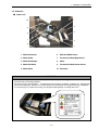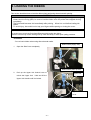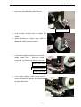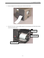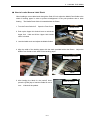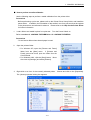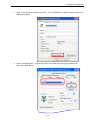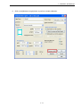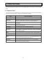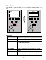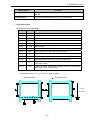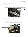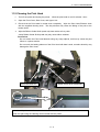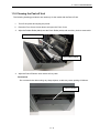
1
TOSHIBA Barcode Printer
B-SX600 SERIES
Owner's Manual
CE Compliance (for EU only)
This product complies with the requirements of EMC and Low Voltage Directives including their
amendments.
VORSICHT:
Maschinenlärminformations-Verordnung 3. GPSGV,
der höchste Schalldruckpegel beträgt 70 dB(A) oder weniger gemäss EN ISO 7779.
Centronics is a registered trademark of Centronics Data Computer Corp.
Microsoft is a registered trademark of Microsoft Corporation.
Windows is a trademark of Microsoft Corporation.
This equipment has been tested and found to comply with the limits for a Class A digital device,
pursuant to Part 15 of the FCC Rules. These limits are designed to provide reasonable rotection
against harmful interference when the equipment is operated in a commercial environment. This
equipment generates, uses, and can radiate radio frequency energy and, if not installed and sed in
accordance with the instruction manual, may cause harmful interference to radio communications.
Operations of this equipment in a residential area is likely to cause harmful interference in which case
the user will be required to correct the interference at his own expense.
(for USA only)
Changes or modifications not expressly approved by manufacturer for compliance could void the
user’s authority to operate the equipment.
“This Class A digital apparatus complies with Canadian ICES-003.”
“Cet appareil numérique de la classe A est conforme à la norme NMB-003 du Canada.”
(for CANADA only)
IP20
< For EU Only >
TOSHIBA TEC Europe Retail Information Systems S.A.
Rue de la Célidée 33 BE-1080 Brussels
Copyright © 2008
by TOSHIBA TEC CORPORATION
All Rights Reserved
570 Ohito, Izunokuni-shi, Shizuoka-ken, JAPAN
Safety Summary
Safety Summary
Personal safety in handling or maintaining the equipment is extremely important. Warnings and Cautions
necessary for safe handling are included in this manual. All warnings and cautions contained in this manual
should be read and understood before handling or maintaining the equipment.
Do not attempt to effect repairs or modifications to this equipment. If a fault occurs that cannot be rectified
using the procedures described in this manual, turn off the power, unplug the machine, then contact your
authorised TOSHIBA TEC representative for assistance.
Meanings of Each Symbol
This symbol indicates warning items (including cautions).
Specific warning contents are drawn inside the symbol.
(The symbol on the left indicates a general caution.)
This symbol indicates prohibited actions (prohibited items).
Specific prohibited contents are drawn inside or near the symbol.
(The symbol on the left indicates “no disassembling”.)
This symbol indicates actions which must be performed.
Specific instructions are drawn inside or near the symbol.
(The symbol on the left indicates “disconnect the power cord plug from the outlet”.)
WARNING
Any other than the
specified AC voltage
is prohibited.
Prohibited
Prohibited
Disconnect
the plug.
This indicates that there is the risk of death or serious injury if the
machines are improperly handled contrary to this indication.
Do not use voltages other than
the voltage (AC) specified on the
rating plate, as this may cause
fire or electric shock.
Prohibited
If the machines share the same
outlet with any other electrical
appliances that consume large
amounts of power, the voltage
will fluctuate widely each time
these appliances operate. Be sure
to provide an exclusive outlet for
the machine as this may cause
fire or electric shock.
Do not insert or drop metal,
flammable or other foreign
objects into the machines through
the ventilation slits, as this may
cause fire or electric shock.
Prohibited
Prohibited
If the machines are dropped or
their cabinets damaged, first turn
off the power switches and
disconnect the power cord plugs
from the outlet, and then contact
your authorised TOSHIBA TEC
representative for assistance.
Continued use of the machine in
that condition may cause fire or
electric shock.
Disconnect
the plug.
(i)
Do not plug in or unplug the power
cord plug with wet hands as this
may cause electric shock.
Do not place metal objects or
water-filled containers such as
flower vases, flower pots or mugs,
etc. on top of the machines. If
metal objects or spilled liquid enter
the machines, this may cause fire
or electric shock.
Do not scratch, damage or modify
the power cords. Also, do not
place heavy objects on, pull on, or
excessively bend the cords, as this
may cause fire or electrical shock.
Continued use of the machines in
an abnormal condition such as
when the machines are producing
smoke or strange smells may cause
fire or electric shock. In these
cases, immediately turn off the
power switches and disconnect the
power cord plugs from the outlet.
Then, contact your authorised
TOSHIBA TEC representative for
assistance.
Safety Summary
If foreign objects (metal
fragments, water, liquids) enter
the machines, first turn off the
power switches and disconnect
the power cord plugs from the
outlet, and then contact your
authorised TOSHIBA TEC
representative for assistance.
Continued use of the machine in
that condition may cause fire or
electric shock.
Ensure that the equipment is
Connect a
properly grounded. Extension
grounding wire.
cables should also be grounded.
Fire or electric shock could
occur on improperly grounded
equipment.
Disconnect
the plug.
Disconnect
the plug.
CAUTION
No
disassembling.
When unplugging the power cords,
be sure to hold and pull on the plug
portion. Pulling on the cord portion
may cut or expose the internal wires
and cause fire or electric shock.
Do not remove covers, repair or
modify the machine by yourself.
You may be injured by high
voltage, very hot parts or sharp
edges inside the machine.
This indicates that there is the risk of personal Injury or damage to
objects if the machines are improperly handled contrary to this indication.
Precautions
The following precautions will help to ensure that this machine will continue to function correctly.
• Try to avoid locations that have the following adverse conditions:
* Temperatures out of the specification
* Direct sunlight
* High humidity
* Shared power source
* Excessive vibration
* Dust/Gas
• The cover should be cleaned by wiping with a dry cloth or a cloth slightly dampened with a mild
detergent solution. NEVER USE THINNER OR ANY OTHER VOLATILE SOLVENT on the plastic
covers.
• USE ONLY TOSHIBA TEC SPECIFIED paper and ribbons.
• DO NOT STORE the paper or ribbons where they might be exposed to direct sunlight, high
temperatures, high humidity, dust, or gas.
• Ensure the printer is operated on a level surface.
• Any data stored in the memory of the printer could be lost during a printer fault.
• Try to avoid using this equipment on the same power supply as high voltage equipment or equipment
likely to cause mains interference.
• Unplug the machine whenever you are working inside it or cleaning it.
• Keep your work environment static free.
• Do not place heavy objects on top of the machines, as these items may become unbalanced and fall
causing injury.
• Do not block the ventilation slits of the machines, as this will cause heat to build up inside the machines
and may cause fire.
• Do not lean against the machine. It may fall on you and could cause injury.
• Care must be taken not to injure yourself with the printer paper cutter.
• Unplug the machine when it is not used for a long period of time.
• Place the machine on a stable and level surface.
Request Regarding Maintenance
• Utilize our maintenance services.
After purchasing the machine, contact your authorised TOSHIBA TEC representative for assistance
once a year to have the inside of the machine cleaned. Otherwise, dust will build up inside the machines
and may cause a fire or a malfunction. Cleaning is particularly effective before humid rainy seasons.
• Our preventive maintenance service performs the periodic checks and other work required to maintain
the quality and performance of the machines, preventing accidents beforehand.
For details, please consult your authorised TOSHIBA TEC representative for assistance.
• Using insecticides and other chemicals
Do not expose the machines to insecticides or other volatile solvents. This will cause the cabinet or
other parts to deteriorate or cause the paint to peel.
( ii )
TABLE OF CONTENTS
Page
1.
PRODUCT OVERVIEW............................................................................................................1- 1
1.1
1.2
1.3
1.4
1.5
2.
PRINTER SETUP .....................................................................................................................2- 1
2.1
2.2
2.3
2.4
2.5
3.
Introduction......................................................................................................................1- 1
Accessories ....................................................................................................................1- 2
Part Names and Functions ..............................................................................................1- 3
1.3.1 Front View ................................................................................................................... 1- 3
1.3.2 Rear View (Model with a USB interface) ..................................................................... 1- 4
1.3.3 Rear View (Model with a LAN interface)...................................................................... 1- 5
1.3.4 Interior ......................................................................................................................... 1- 6
1.3.5 Operation Panel........................................................................................................... 1- 8
Cutter Unit ............................................................................................................................. 1- 9
1.4.1 Cut Position ................................................................................................................. 1- 9
1.4.2 Precautions when using the Cutter Unit ..................................................................... 1-10
Peel-off Unit.......................................................................................................................... 1-11
1.5.1 Part Names................................................................................................................. 1-11
1.5.2 Precautions when using the Peel-off Unit................................................................... 1-12
Removing the Protective Materials ..................................................................................2- 1
Installation Location.........................................................................................................2- 4
Connecting the Power Cord ............................................................................................2- 5
Connecting the Printer (with a USB interface) to Your Computer....................................2- 6
Connecting the Printer (with a LAN interface) to Your Computer ....................................2- 7
MEDIA AND RIBBON ..............................................................................................................3- 1
3.1
3.2
3.3
3.4
3.5
3.6
3.7
Supply Specifications ......................................................................................................3- 1
Die-cut Label ...................................................................................................................3- 2
Notched Media ................................................................................................................3- 3
Label with Black Marks....................................................................................................3- 4
Guaranteed Print Area.....................................................................................................3- 5
Storage of Media and Ribbon..........................................................................................3- 6
Unacceptable Media and Ribbons...................................................................................3- 6
4.
LOADING THE RIBBON ..........................................................................................................4- 1
5.
LOADING THE MEDIA.............................................................................................................5- 1
5.1
5.2
5.3
How to Load the Media....................................................................................................5- 1
How to Load the Media for the Model with the Peel-off Unit............................................5- 5
How to Load Fanfold Paper............................................................................................5-11
6.
PRINTING FROM YOUR COMPUTER ....................................................................................6- 1
6.1
6.2
7.
PRINTER OPERATION............................................................................................................7- 1
7.1
7.2
7.3
7.4
8.
Media Feed Mode............................................................................................................7- 1
Tear-off ............................................................................................................................7- 4
Page Alignment ...............................................................................................................7- 5
Media Calibration.............................................................................................................7- 8
OPERATION PANEL ...............................................................................................................8- 1
8.1
8.2
8.3
8.4
8.5
9.
Print Test from Printer Driver ...........................................................................................6- 1
Precautions when Using the Model with a LAN Interface................................................6- 4
Operation Panel...............................................................................................................8- 1
Messages Displayed on the Operation Panel .................................................................8- 2
Printer Operation Using the Operation Panel ..................................................................8- 6
Menu Options ..................................................................................................................8- 7
How to Cancel a Print Job ..............................................................................................8-12
TEST PRINT .............................................................................................................................9- 1
9.1
9.2
How to Perform a Print Test ............................................................................................9- 1
Print Test Pattern.............................................................................................................9- 1
10. REMOVING JAMMED MEDIA ................................................................................................10- 1
10.1 Removing Jammed Media from the Cutter Unit.............................................................10- 1
10.2 Removing Jammed Media from the Peel-off Unit ..........................................................10- 2
11. DAILY MAINTENANCE...........................................................................................................11- 1
11.1
11.2
11.3
11.4
11.5
11.6
Cleaning the Media Sensor ...........................................................................................11- 2
Cleaning the Platen .......................................................................................................11- 3
Cleaning the Ribbon Separation Plate ..........................................................................11- 4
Cleaning the Ribbon Guide Bar .....................................................................................11- 4
Cleaning the Print Head ................................................................................................11- 5
Cleaning the Peel-off Unit..............................................................................................11- 6
12. TROUBLESHOOTING ............................................................................................................12- 1
12.1
12.2
12.3
12.4
12.5
Problems at Start-up of the Printer ................................................................................12- 1
Problems while Printing .................................................................................................12- 1
Print Failure ...................................................................................................................12- 4
Problems in the Network (Model with a LAN Interface) .................................................12- 8
Solutions if an Error Message Appears on the Operation Panel ...................................12- 9
13. FREQUENTLY ASKED QUESTIONS (FAQ)..........................................................................13- 1
14. SPECIFICATIONS...................................................................................................................14- 1
14.1
14.2
14.3
14.4
Printer (Model with a USB Interface) .............................................................................14- 1
Printer (Model with a LAN Interface) .............................................................................14- 2
Cutter Unit .....................................................................................................................14- 4
Peel-off Unit...................................................................................................................14- 4
15. POWER CORD........................................................................................................................15- 1
WARNING!
This is a Class A product. In a domestic environment this product may cause radio interference in
which case the user may be required to take adequate measures.
CAUTION!
1. This manual may not be copied in whole or in part without prior written permission of TOSHIBA
TEC.
2. The contents of this manual may be changed without notification.
3. Please refer to your local Authorised Service representative with regard to any queries you may
have in this manual.
1. PRODUCT OVERVIEW
1.1 Introduction
Thank you for choosing the TOSHIBA B-SX600 series bar code printer
This Owner’s Manual includes instructions and directions for use of the printer. It should be read
carefully to make full use of the capabilities of the printer and maximize its life. Particularly, please
read “Safety Summary” before handling or maintaining the printer. For most queries please refer to
this manual and keep it safe for future reference. Please contact your nearest authorised TOSHIBA
TEC representative for further information concerning this manual.
1- 1
1. PRODUCT OVERVIEW
1.2 Accessories
When unpacking the printer, please make sure all the following accessories are supplied with the
printer. Should any of them be missing, please contact your nearest authorised TOSHIBA TEC
representative for assistance.
• CD-ROM
• Owner’s Manual (this document)
• Ferrite core (for the model with a LAN interface)
• Reset pin (for the model with a LAN interface)
• Unpacking instructions
• Warranty sheet (US only)
• Cleaning cloth
1- 2
1. PRODUCT OVERVIEW
1.3 Part Names and Functions
1.3.1 Front View
1
2
8
3
4
7
6
5
5. Media Outlet
1. Side Cover
Printed outputs are ejected through the Media
Outlet.
Opened when the media or ribbon is loaded
or replaced.
6. Front Cover
2. Supply Window
Opened when the media is loaded or replaced.
A remaining quantity of the media or ribbon
can be checked through the Supply Window.
7. Power Switch
3. Front Cover Unlock Button
Used to turn the printer on/off.
Used to open the Front Cover.
8. Operation Panel
4. Side Cover Grip
Please refer to Section 8. OPERATION PANEL
for further information.
Used to open the Side Cover.
1- 3
1. PRODUCT OVERVIEW
1.3.2 Rear View (Model with a USB interface)
1
2
5
3
4
1.
3.
USB Interface Connector
Used to interface with an external device.
Used to connect the printer to a PC with a
USB cable.
2.
Expansion I/O Interface Connector
Ventilation Slot
Lets trapped heat pass out of the printer.
4.
AC Power Inlet
5.
Fanfold Paper Slot
Allows fanfold paper to feed into the printer from
the printer back.
1- 4
1. PRODUCT OVERVIEW
1.3.3 Rear View (Model with a LAN interface)
1
2
5
3
4
1.
3.
LAN Interface Connector
Used to interface with an external device.
Used to connect the printer to a PC with
a LAN cable. .
2.
Expansion I/O Interface Connector
Ventilation Slot
Lets trapped heat pass out of the
printer
4.
AC Power Inlet
5.
Fanfold Paper Slot
Allows fanfold paper to feed into the printer
from the printer back.
1- 5
1. PRODUCT OVERVIEW
1.3.4 Interior
■ Lower unit
10
1
2
9
3
8
7
4
6
5
1. Media End Sensor
6.
Reflective Media Sensor
2. Media Holder
7.
Transmissive Media Edge Sensor
3. Media Roll Damper
8.
Platen
4. Media Roll Guide
9.
Transmissive Media Centre Sensor
5. Media Guide
10. Print Head
WARNING!
1. Do not touch the Print Head or around it just after printing. You may get burned as the Print Head
becomes very hot during printing.
2. Do not touch any moving parts. To reduce the risk of fingers, jewellery, clothing, etc., being drawn
into the moving parts, be sure to load the media once the printer has stopped moving completely.
3. To avoid injury, be careful not to trap your fingers while opening or closing the cover.
1- 6
1. PRODUCT OVERVIEW
■ Upper Unit
1
2
7
3
4
6
5
1. Upper Unit Handle
5.
Ribbon Tensioner
2. Upper Unit Unlock Lever
6.
Print Head Pressure Selection Lever
3. Ribbon Stopper
7.
Ribbon Shaft (Take-up side)
4. Ribbon Shaft (Supply side)
1- 7
1. PRODUCT OVERVIEW
1.3.5 Operation Panel
1
2
11
10
3
9
4
5
8
6
7
1. LCD Message Display
7.
[Enter] key
2. Error LED (Red)
8.
Arrow keys
3. Data LED (Green)
9.
[Pause] key
4. [Feed] key
10. Power LED (Green)
5. [Menu] key
11. Ready LED (Green)
6. [Cancel] key
Please refer to Section 8. OPERATION PANEL for further information about the Operation
Panel.
1- 8
1. PRODUCT OVERVIEW
1.4 Cutter Unit
This section describes the model with the Cutter Unit.
The model with the Cutter Unit is designed to cut the printed media.
A cutter is located inside the Media Outlet.
1.4.1 Cut position
A cut position varies depending on media feed mode selected.
Cut position
• Strict feed mode
In the Strict feed mode, the cut position is at the
centre of a gap, a notch or a black mark.
Cut position
• Easy feed mode
In the Easy feed mode, the cut position is
approximately 1 mm from the leading edge of the
label positioned behind the cutter.
Feed direction
Media pitch specified in
the printer driver
• Fixed length feed mode
In the Fixed Length feed mode, the media is cut
at equal interval of media pitch specified in the
printer driver.
Feed direction
1- 9
Cut position
1. PRODUCT OVERVIEW
1.4.2 Precautions when using the Cutter Unit
The following precautions must be taken when the Cutter Unit is used.
・
The thickness of the media that
can be cut is between 0.08 mm
and 0.26 mm.
Do not cut any
media that falls outside this
Cut position
カット位置
range, as this may cause a
printer failure.
・
When using a label stock, be
sure to cut the gaps.
Label
ラベル
Cutting
labels will cause the glue to stick
to the cutter, which may affect the
Backing
台紙
paper
cutter quality and shorten the
cutter life.
・
Do not cut any materials other than
・
The cutter is a consumable.
The
cutting edge wears out from an
extended period of use, causing the
cutter to be blunt.
When replacing the
cutter, please contact your nearest
authorised TOSHIBA TEC
Perforation
ミシン目
representative for assistance.
・
カット禁止領域
Area
where cutting is
not allowed
may cause a printer failure.
±1 mm
paper (e.g. fabrics and films), as this
When the perforated media is used, do
not cut ± 1 mm around the perforation,
as this may cause a paper jam in the
Cutter Unit.
1- 10
1. PRODUCT OVERVIEW
1.5 Peel-off Unit
This section describes the model with the Peel-off Unit.
1.5.1 Part names
Media Holding Roller
Front Cover
Peel-off Sensor
Front Cover Unlock button
Peel-off Unit
Pinch Roller (White)
Peel-off Sensor
Rubber Roller (Black)
Media Holding Roller
1- 11
1. PRODUCT OVERVIEW
1.5.2 Precautions when using the Peel-off Unit
The following precautions must be taken when the Peel-off Unit is used.
・
・
・
・
・
Reduce a print speed to 101.6 mm/second (4 ips) or less.
Do not use perforated media, as this may cause a media feed error.
Some die-cut labels may not be peeled properly depending on the die-cut condition.
Please remove a label after peeling and media feed are stopped completely.
When the printer is not used in Strip mode, draw the media and backing paper together
over the Media Holding Roller until the leading edge of the media comes out of the
media outlet.
The media should be sufficiently pulled out so that it is kept held by the
Media Holding Roller even after the media is fed backward after a tear-off.
Otherwise,
a media feed error may occur.
・
The Peel-off Sensor may malfunction if it is subject to direct lighting of a three-band
fluorescent lamp.
If this happens, decrease the illumination intensity of the fluorescent
lamp or relocate the printer.
・
Do not use the edge of the Peel-off Plate to tear off the media, as this may cause injuries
or a printer failure.
・
When the printer is used in Strip mode, enable “Peel” in the printer driver.
For details,
please refer to the Help for the Printer Driver.
Supplemental Remarks
・ The Rubber Roller in the Peel-off Unit is a consumable.
It wears out from an extended
period of use, which causes an improper peel-off operation.
As a guide, it should be
replaced when the printer running distance reaches 20 km. When replacing the Rubber
Roller, please contact your nearest authorised TOSHIBA TEC representative for assistance.
1- 12
2. PRINTER SETUP
2.1 Removing the Protective Materials
CAUTION
Please be careful not to get your fingers caught in the covers while opening
or closing them. This may cause injuries.
Precautions
•
Do not plug in the Power Cord until the printer is set up completely.
1.
Hold the Side Cover Grip and open the Side Cover completely.
Side Cover Grip
2.
Push up the Upper Unit Unlock Lever (underneath the Upper Unit Handle) to unlock the Upper
Unit.
3.
Hold and lift the Upper Unit Handle until it is locked.
Upper Unit Handle
Upper Unit Unlock Lever
2- 1
2. PRINTER SETUP
4.
Remove the black plastic band that is
used to fasten the Ribbon Tensioner of
Ribbon Tensioner
the Upper Unit.
Black plastic band
5.
Press the Front Cover Unlock button and open the Front Cover frontward.
Front Cover
Front Cover Unlock Button
6.
Lift the Media Holder Plate.
Remove the Print Head Protective Sheet.
Print Head Protective Sheet
Media Holder Plate
7.
Push up the Upper Unit Unlock Lever to unlock the Upper Unit.
2- 2
2. PRINTER SETUP
8.
Take your finger off the Upper Unit Unlock
Lever.
Hold the Upper Unit Handle and
push the Upper Unit downward until it is
locked.
Ensure that the Upper Unit is locked
completely.
9.
Close both the Front and the Side Covers.
2- 3
2. PRINTER SETUP
2.2 Installation Location
Install the printer in a place where ample space is reserved for operation. Also, place the printer on a
well ventilated, flat, level table or a rack specifically designed for the printer.
Make sure that the 4 feet
of the printer make full contact with the surface of the desk or rack.
Ensure that there is sufficient space around the printer, as illustrated below.
%RH
5 °C 90%
29 °C 90%
80
18 °C
60%
60
40
28 °C
60%
5 °C
55%
18 °C
40%
20
Back: 5 cm or over
28 °C
40%
40 °C 39%
Left: 10 cm or over
40 °C 10%
10
20
Acceptable
operating
range
CAUTION
30
°C
40
Recommended
operating range
Right: 30 cm or over
Front: 15 cm or over
Avoid locations that have the following adverse conditions. Failure to
do this may cause injuries or printer failure.
・ Direct sunlight
・ High temperatures and humidity or low temperatures and humidity
・ Rapid temperature changes
・ Direct cold air
・ Excessive vibration
・ Dust/Gas
・ Near magnetic or electromagnetic devices
・ Near open flames or wet locations
・ On an unstable desk or rack
Precautions
・ Ensure that an AC outlet is located near the installation location of the printer and that it allows for the
easy plugging and unplugging of the Power Cord.
Do not place any obstacles around the AC outlet.
・ When the Peel-off Unit is used, the backing paper is ejected continuously from the lower section of the
Peel-off Unit. Particularly, when a label in use is long, choose an installation location carefully in
order to prevent it from sticking on a table or the ejected backing paper.
2- 4
2. PRINTER SETUP
2.3 Connecting the Power Cord
This section describes how to connect the Power Cord and turn the printer on or off.
Precautions
• As a Power Cord is not supplied with the printer, please purchase an approved on that meets the
safety standard of each country. Refer to Section 15. POWER CORD.
• Ensure that an AC outlet is located near the installation location of the printer and that it allows for the
easy plugging and unplugging of the Power Cord. Do not place any obstacles around the AC outlet.
• Make sure that the printer is connected to a clean source of AC power and that no other high voltage
devices that may cause line noise interference are connected to the same mains. Otherwise, this
may affect the operation of the printer.
1.
Make sure that the printer Power Switch is in the OFF ( ) position.
OFF
2.
ON
Completely plug the Power Cord into the AC
Power Inlet at the back of the printer.
3.
Plug the other end of the Power Cord into a grounded outlet as far as it will go.
[Example of US Type]
2- 5
[Example of EU Type]
2. PRINTER SETUP
2.4 Connecting the Printer (with a USB Interface) to Your Computer
1.
Connect the smaller end of the USB cable to the
USB Interface Connector at the back of the
printer.
2.
Connect the other end of the USB cable to a
USB port of your computer.
Supplemental Remarks
・ If a USB cable other than the supplied one or other USB devices are used, choose USB
2.0-compatible products.
・ Pay attention to the orientation of the connector when connecting the USB cable.
・ It is not guaranteed that the printer functions in combination with any other USB devices (e.g.
USB flash memory).
If a USB device is used together with the printer at the same time, it may
not be detected properly depending on the combination of a USB device and a computer in use.
In this case, use of a USB hub between the USB device and the PC is recommended.
・ Choose a fully shielded USB cable that best fits your needs or environment.
2- 6
2. PRINTER SETUP
2.5 Connecting the Printer (with a LAN Interface) to Your Computer
1.
Fit the supplied ferrite core close to the
connector of the LAN cable.
(See the photo on
the right.)
2.
Connect the ferrite core fitted end of LAN cable
into the LAN Interface Connector at the back of
the printer.
3.
Connect the other end of the LAN cable into a
network device such as a hub.
Precautions
・ Be sure to fit the supplied ferrite core to a LAN cable.
If a different ferrite core is fitted to the
cable, communications with the computer may become unstable.
・ Pay attention to the orientation of the connector when connecting the LAN cable.
・ Choose a LAN cable that best fits your needs or environment.
2- 7
3. MEDIA AND RIBBON
3.1 Supply Specifications
Item
Media width (Backing
paper width)
Media thickness (total)
Media pitch
Label length
Label width
Label thickness
Backing paper
thickness
Material of backing
paper
Media type (Roll
direction)
Max. outside roll
diameter
Inner core diameter
Ribbon width
Ribbon roll direction
Ribbon inner core
diameter
End of ribbon
Outside roll diameter
Batch/Tear-off mode
Strip mode
15 mm to 120 mm
Cut mode
5 mm to 1,000 mm
-
0.08 mm to 0.26 mm
12 mm to 1,000 mm
10 mm to 998 mm ∗1
10 mm or more
0.05 mm or more
0.1 mm or less
10 mm to 1,000 mm
-
-
Glassine paper
-
Roll (Inside/outside)
Fanfold ∗2
Roll (Inside)
Roll (Inside/outside)
Fanfold
∅200 mm
∅76.2 mm
30 to 120 mm (A ribbon must be at least 10 mm wider than the loaded
media.)
Ink side faces outside
∅25.4 mm to ∅ 26.4 mm
Minimum of 200 mm long silver film is attached to the end of the ribbon.
∅70 mm or less (Ribbon length: Approx. 300 m or less)
∗
1 If the length of a label is long, place the printer on a surface where an ejected label does not
stick to the printer or floor.
∗
2 Feed fanfold paper from back of the printer.
(→ 5.3 How to Load Fanfold Paper)
∗
3 Use a ribbon that is at least 10 mm wider than the media.
Supplemental Remarks
・ In the case of peel-off operation, use of perforated labels is not allowed.
・ Feed fanfold paper through the Fanfold Paper Slot on the printer back.
3- 1
3. MEDIA AND RIBBON
3.2 Die-cut label
“Die-cut label” refers to a label stock of which labels are die cut one by one and surroundings are
removed, as illustrated below.
When a die-cut label stock is loaded, either the Transmissive Media Edge Sensor or the
Transmissive Media Centre Sensor is used to detect a print position. The Transmissive Media
Centre Sensor is located at the centre of the label feed path. (→ 1.3 Part Names and
Functions)
Precautions
・ The Transmissive Media Edge Sensor must be placed so that it does not come into contact with
the media.
15 to 120 mm
20 mm or less
Gap
2 to 13 mm
R2 mm or less
25 mm
Label pitch
5 to 1,000 mm
Page start line
Transmissive Media
Edge Sensor
Media feed direction
3- 2
3. MEDIA AND RIBBON
3.3 Notched media
“Notched media” is notched on the left at a regular interval.
When notched media is loaded, the
Transmissive Paper Edge Sensor is used.
Precautions
・ The Transmissive Paper Edge Sensor must be placed so that it does not come into contact with
the media.
15 to 120 mm
Notch
2 to 13 mm
4 mm or over
Transmissive Paper Edge Sensor
Page start line
Media feed direction
3- 3
3. MEDIA AND RIBBON
3.4 Label with black marks
“Label with black marks” refers to a label stock with black marks printed at the back of the
backing paper for the position detection purpose, as illustrated below.
When a label stock with
black marks is loaded, the Reflective Media Sensor is used.
15 to 120 mm
12 mm or over
2 to 13 mm
Label pitch
10 to 1,000 mm
Black mark on the
reverse side
Page start line
Reflective Media Sensor
(Located under the media)
Media feed direction
3- 4
3. MEDIA AND RIBBON
3.5 Guaranteed Print Area
Printing must be performed within the shaded area as illustrated below.
If a printed image is placed outside this area, the loaded ribbon may be torn or the print quality may be
degraded.
1.
Die-cut label
A
A
Label length
B
B
Label width
Media width
A = 2 mm or over
B = 1.5 mm (if a label length is 100 mm or less)
B = 2.5 mm (if a label length is more than 100 mm)
2.
Notched media
B
A
A
B
Media width
A = 2 mm or over
B = 1.5 mm (if a notch pitch is 100 mm or less)
B = 2.5 mm (if a notch pitch is more than 100 mm)
3- 5
3. MEDIA AND RIBBON
3.6 Storage of Media and Ribbons
・
・
・
Store the media and ribbon in a cool, dry place. Avoid areas where they would be exposed to
direct sunlight, high temperature, high humidity, dust or gas.
Store the media in a plastic bag so as not to collect dust or dirt particles.
Store media rolls on the flat end. Do not store them on the curved sides as this might flatten
that side causing erratic media advance and poor print quality.
3.7 Unacceptable Media and Ribbons
・ Wrinkled, folded, or ripped media
・ Media on which dust particles settle on
・ Media or ribbon whose edge is wavy
・ Curled media
・ Damp media or ribbon
・ Media or ribbon already used for printing
・ Media whose surface is treated (except for designated media)
・ Media whose thickness does not meet the specifications
・ Perforated or punched media (except for designated media)
・ Label from which adhesive squeezes out
・ Partially darkened media
・ Media or ribbons of which shelf life is expired
When you purchase media and ribbons
There are a wide variety of media or ribbons depending on what they are made of and how the
front and back surfaces are treated.
Please use only TOSHIBA TEC-approved or recommended media and ribbons in order to ensure
the best print quality.
TOSHIBA TEC shall not be liable for any print failures or defects arising from the use of
non-approved media or ribbons.
Preprinted Media
When preprinted media (for instance, media with a box already printed on it) is used for printing,
the Print Head may be damaged by the ink used for preprinting. Particularly, if pigment-based ink
is used for preprinting, the life of the Print Head will be considerably reduced. Please contact
your nearest authorised TOSHIBA TEC representative for further information before using
preprinted media.
If you use media with preprints on the back and have the Reflective Media Sensor (designed to
detect black marks) detect black marks, please consult your nearest authorised TOSHIBA TEC
representative. The Reflective Media Sensor is only applicable to the media with preprints
printed with special ink.
3- 6
3. MEDIA AND RIBBON
Handling the loaded media in the event of a media end or a ribbon end
In general, at the time of a media end or a ribbon end, printing on media that is about to be ejected
from the printer has not been completed.
If all print images have been printed on the media and non-print area remains, it looks as if printing
were completed.
However, the printer does not determine that printing is completed unless an
entire page is completely fed.
In this situation, there are two options for restarting printing:
(1) If [Yes] is selected for [Reprint Error Page] in the Menu of the printer, printing will be
restarted from the most recently printed page at the time of media end or ribbon end.
(2) If [No] is selected, printing will be restarted from the page subsequent to the most recently
printed one at time of Media End or Ribbon End.
3- 7
(→ 8. OPERATION PANEL)
4. LOADING THE RIBBON
This section describes how to load the ribbon when performing thermal transfer printing.
WARNING!
1. Do not touch any moving parts. To reduce the risk of fingers, jewellery, clothing, etc., being
drawn into the moving parts, be sure to load the ribbon once the printer has stopped moving
completely.
2. The print head becomes hot immediately after printing. Allow it to cool before loading the
ribbon.
3. To avoid injury, be careful not to trap your fingers while opening or closing the cover.
CAUTION!
Be careful not to touch the Print Head Element while loading the ribbon.
Failure to do this may cause missing dots by static electricity or other print quality problems.
Precaution
・ Do not load a ribbon when using direct thermal media.
Ribbon Shaft (Supply side)
1.
Open the Side Cover completely.
Ribbon Shaft (Take-up side)
2.
Push up the Upper Unit Unlock Lever to
unlock the Upper Unit.
Upper Unit
Hold and lift the
Upper Unit Handle until it is locked.
Upper Unit Unlock
Lever
4- 1
4. LOADING THE RIBBON
3.
Hold down the Release button and move
Ribbon Shaft (Supply side)
the Ribbon Stopper along the Ribbon Shaft
(Supply side) to the width of the ribbon in
Ribbon Stopper
use with reference to the Scale on the
ribbon shaft.
Release button
4.
Scale
Fit a new ribbon onto the Ribbon Shaft
(Supply side).
Load the ribbon so that it
unrolls from the back side.
[Supplemental Remarks]
Gently squeeze metal plate.
・ The ribbon can be placed on the Ribbon
Shaft (Supply side) more easily by gently
Metal
plate
holding and squeezing the centre of the
metal plate of the Ribbon Shaft (Supply
side).
4- 2
4. LOADING THE RIBBON
5.
In the same way described in Step 3, move
the Ribbon Stopper of the Ribbon Shaft
(Take-up side) in accordance with the width
of the Ribbon Core.
Fit a Ribbon Core
onto the Ribbon Shaft (Take-up side).
[Supplemental Remarks]
・ The Ribbon Core can be placed on the
Ribbon Shaft (Take-up side) more easily
by gently holding and squeezing the
Metal
plate
centre of the metal plate of the Ribbon
Shaft (Take-up side).
Gently squeeze the metal. plate.
6.
Unroll and draw the ribbon under the Upper
Unit, and affix the leading edge of the ribbon
(self-adhesive) to the Ribbon Core.
7.
Turn the knob of the Ribbon Shaft (Take-up
side) several times to take up the ribbon.
Precautions
・ Be careful not to twist or wrinkle the ribbon
while taking up the ribbon onto the Ribbon
Core.
4- 3
4. LOADING THE RIBBON
8. Push up the Upper Unit Unlock Lever to unlock
the Upper Unit. Hold the Upper Unit Handle
and push the Upper Unit downward until it is
locked.
Precautions
・ Whenever the Upper Unit is lifted in the event
of an error, turn the knob of the Ribbon Shaft
(Take-up side) several times to take up the
ribbon before closing the Upper Unit.
4- 4
5. LOADING THE MEDIA
This section describes how to load the media.
Before using the Peel-off Unit or fanfold paper, please read Section 5.1 How to Load the Media
carefully first. Then, refer to section 5.2 How to Load the Paper for the Model with the Peel-off
Unit or section 5.3 How to Load Fanfold Paper.
WARNING!
1. Do not touch any moving parts. To reduce the risk of fingers, jewellery, clothing, etc., being
drawn into the moving parts, be sure to load the media once the printer has stopped moving
completely.
2. The Print Head becomes hot immediately after printing. Allow it to cool before loading the
media.
3. Care must be taken not to catch your fingers in the covers when opening or closing them.
NOTE:
For the specification of available media, refer to Section 3.1 Supply Specifications.
5.1 How to Load the Media
1.
Open the Side Cover completely.
2.
Push up the Upper Unit Unlock Lever to
unlock the Upper Unit.
Hold and lift the
Upper Unit Handle until it is locked.
Upper Unit
Upper Unit
3.
Unlock Lever
While squeezing the Unlock Levers of the
Media Roll Holder, slide the Media Roll Holder
Unlock Lever
outside.
Media Roll Holder
5- 1
5. LOADING THE MEDIA
4.
Push down the Media Roll Holder outward.
Media Roll Holder
5.
Load a media roll, and raise the Media Roll
Holder.
6.
While squeezing the Unlock Levers, push the
Media Roll Holder against the media.
7.
If the loaded media is outside wound, raise the
Media Holder Plate.
Draw the media
underneath the Media Roll Damper and the
Media Roll Guide.
Media Holder Plate
Media Roll Damper
Media Roll Guide
8.
If the loaded media is inside wound, draw it
above the Media Roll Damper and underneath
the Media Roll Guide.
5- 2
5. LOADING THE MEDIA
[Supplemental Remarks]
・ When using an inside wound media with the
Peel-off Unit, do not use the Media Roll Damper.
Draw the media underneath the Media Roll
Damper and the Media Roll Guide.
9.
Adjust the Media Guide to the width of the media.
[Supplemental Remarks]
・ Make sure that the print side faces upward.
・ Fit the Media Guide to the media edges.
Failure to do this may cause a misalignment of
print position or ribbon wrinkles.
10. Set the Print Head Pressure Selection Lever in accordance with the width of the loaded media.
Print Head Pressure Selection Lever
Low pressure
High pressure
5- 3
Media width
(mm)
Print head
pressure
Marking on
the lever
15 to 30
Low
I
30 to 60
Medium
II
60 to 120
High
III
5. LOADING THE MEDIA
11. Select an appropriate media sensor in accordance with the type of the loaded media.
Place
the sensor in a right position.
Transmissive Media Edge Sensor
Transmissive
Media
Centre Sensor
Reflective Media Sensor
[Supplemental Remarks]
・ Refer to section 3. MEDIA AND RIBBON for further information regarding the combination of
the media type and the sensor to be used.
12. Draw the media frontward. Adjust both sides of the leading edge of the media so that the
media is centred above the scale.
Scale
13. Lower the Media Holder Plate. Push up the Upper Unit Unlock Lever and close the Upper
Unit.
5- 4
5. LOADING THE MEDIA
5.2 How to Load the Media for the Model with the Peel-off Unit
* Please read section 5.1 How to Load the Media first.
* If the label in use is too long, place the printer where a printed label is not stuck to the printer or
the table.
1.
Press the Front Cover Unlock button and open the
Front Cover Unlock Button
Front Cover.
2.
Refer to Section 5.1 How to Load the Media and load the media.
Place the leading edge of
the label 5 - 10 mm behind the leading edge of the strip plate.
[Supplemental Remarks]
・Be sure to place the leading edge of a label within this range. Failure to do this may cause a
feed error.
Leading edge of label
5 to 10 mm
Leading edge of Strip Plate
5- 5
5. LOADING THE MEDIA
3.
When performing a media calibration from your host computer, pull out the media through the
Media Outlet, not through the Peel-off Unit.
If a calibration is performed with the media set
through the Peel-off Unit, multiple labels will be peeled at the same time, and stick on the printer.
After the completion of the calibration, ensure that the distance between the media outlet and
the leading edge of the media is 15 cm or over.
until the distance becomes 15 cm or over.
If it is less than 15 cm, repeat the calibration
(Use this procedure particularly if the media length
is short.)
15 cm or over
Precautions
・ When performing the “media calibration” from your host computer, ensure that the “peel”
checkbox in the “Options” tab in the printer driver is unchecked.
If the “peel” checkbox is checked, peeling will fail. Consequently, the media calibration will not
be performed successfully.
5- 6
5. LOADING THE MEDIA
4.
Remove all labels from the backing paper outside the Media Outlet.
5.
Open the Front Cover, insert the backing paper into the slot between the Rubber Roller (black)
and the Pinch Roller (white).
Backing paper
Rubber Roller (black)
Pinch Roller (white)
5- 7
5. LOADING THE MEDIA
6.
Take the slack out of the backing paper coming out of the Front Cover.
until both sides of the cover click into place.
7.
Close the Front Cover
Now, the printer is ready for printing.
Once printing is initiated, a printed label is separated from the backing paper and ejected from
the media outlet of the Peel-off Unit. If multiple labels are printed, the previously peeled label
must be removed before a subsequent one is ejected.
5- 8
5. LOADING THE MEDIA
■ How to Load a Narrow Label Stock
When loading a narrow label stock though the Peel-off Unit, adjust the Media Feed Guide to the
width of backing paper in order to prevent misalignment of the print positions due to skew
feeding.
The Media Feed Guide is located behind the Platen
1. Turn the Power Switch off.
Open the Front Cover.
Media Guide
2. Push up the Upper Unit Unlock Lever to unlock the
Upper Unit. Hold and lift the Upper Unit Handle
until it is locked.
3. Load the label stock and adjust the Media Guides.
4. Align the width of the backing paper with the scale provided behind the Platen.
Adjust the
Media Feed Guide to both sides of the backing paper.
Media Feed Guide
Scale
Platen
5. After loading the label for the peel-off issue,
press the [Feed] key to feed the media 50 mm or
over.
A label will be peeled.
5- 9
A label is peeled.
5. LOADING THE MEDIA
■ How to Reload the Media when the Upper Unit is Lifted
When the Upper Unit is lifted in the event of an error during printing in Strip mode, reload the
media using the following steps.
Printing can be restarted while minimizing waste of the media.
1. Open the Front Cover, Side Cover, and Upper Unit.
2. If printing is stopped due to an occurrence of an error, remove the failed label from the
backing paper.
3. Turn the knob of the Ribbon Shaft (Take-up side) to take up the ribbon of 100 mm or over.
4. Reload the media.
Place the leading edge of the label 5 - 10 mm behind the leading edge of
the strip plate.
[Supplemental Remarks]
・ Be sure to place the leading edge of a label within this range.
Failure to do this may cause a
feed error.
Leading edge of label
5 to 10 mm
Leading edge of Strip Plate
5- 10
5. LOADING THE MEDIA
5. Close the Upper Unit and the Side Cover.
6. Take the slack out of the backing paper coming out of the Front Cover.
Cover until both sides of the cover click into place.
5.3 How to Load Fanfold Paper
* Please read section 5.1 How to Load the Media first.
Feed fanfold paper from back of the printer as shown below.
5- 11
Close the Front
6. PRINTING FROM YOUR COMPUTER
This section explains general printing steps, including how to perform a print test from the Windows
Vista/Windows XP/Windows 2000-based printer driver.
[Supplemental Remarks]
・Steps may vary depending on the application software in use.
Please refer to a relevant manual of the application software in use for further information.
6.1 Print Test from Printer Driver
Precautions
・ Before performing a print test, please refer to the Printer Driver Setup Guide, and install the
printer driver.
In addition, the properties of the media in use for a print test must be entered in
the printer driver and selected in advance. Please refer to the Help for the Printer Driver for
further information.
1.
Load the ribbon and media in place for a print test.
Turn the Power Switch on.
Please refer to sections 4. LOADING THE RIBBON and 5. LOADING THE MEDIA for further
information regarding how to load the ribbon and media.
Precautions
・ Do not load a ribbon when thermal paper is used.
2.
Open the “printers” folder.
・
For Windows XP, open the [Printers and Faxes]
folder from the [Start] menu.
If [Printers and
Faxes] cannot be found, open the folder from the
Control Panel.
・
For Windows 2000, click on the [Start] button.
Move the cursor to [Settings] and select [Printers].
6- 1
6. PRINTING FROM YOUR COMPUTER
3.
Right-click an icon of the currently selected printer.
Choose and click on the [Properties].
The
“B-SX600-HS11-QM-R Properties” dialog box appears.
4.
Click on the [Printing References] button.
The “B-SX600-HS11-QM-R Printing Preferences”
dialog box appears.
6- 2
6. PRINTING FROM YOUR COMPUTER
5.
Click on the [Basic] tab.
Choose the media to use from the [Label Type] pull-down list.
6.
Click on the [Print Test Page] in the “B-SX600-HS11-QM-R Properties” dialog box to start a
print test.
6- 3
6. PRINTING FROM YOUR COMPUTER
6.2 Precautions when Using the Model with a LAN Interface
An LPR queue name must be “lp.”
If LPR is selected for print protocol, but a name other than “lp” is designated as a queue name,
printing cannot be performed.
To check a currently designated LPR queue name, click [Ports] tab in the “printer properties” dialog
box, and select a corresponding LPR port.
After that, click the [Port Settings] button.
following dialog box appears.
If RAW is selected for print protocol, no queue name needs to be designated.
6- 4
The
6. PRINTING FROM YOUR COMPUTER
If LPR is selected for print protocol, open the “B-SX600-HS11-QM-R Printing Preferences” dialog
box, click the [Device Settings] tab, and remove the check from the “Obtain printer information”
checkbox.
If printing is performed with LPR selected for print protocol and the “Obtain printer information”
checkbox checked, subsequent printing may fail.
The printer (with a LAN interface) must be on the same network segment as the computer on which
such utilities as Quick Setup and Printserver Version Up Tool (for the model with a LAN interface)
run.
If the computer and the printer (with a LAN interface) are not on the same network segment, a
problem will occur.
For instance, the configuration of the printer (with a LAN interface) cannot be
set up from the Quick Setup or Printserver Version Up Tool utility.
Ensure that the printer (with a LAN interface) and the computer are connected on the same network
segment before using these utilities.
6- 5
7. PRINTER OPERATION
7.1 Media Feed Mode
The following 3 media feed modes are available in the printer:
• Fixed Length feed mode
Printing is performed while gaps, black marks, or notches are being ignored.
When using a media stock with no gaps, black marks, or notches, the printer must be placed in
Fixed Length feed mode.
• Strict feed mode
Printing is performed while gaps or black marks of the media are being detected.
Strict feed mode should be selected when using a media stock with gaps, black marks, or notches
and it is required to check a missing label, media length, or sensor level strictly.
• Easy feed mode
Printing is performed while gaps or black marks of the media are being detected.
Easy feed mode should be selected when using a media stock with gaps, black marks, or notches,
and it is required to continue printing even if the actual media size is slightly different from the
media size entered in the printer driver, or even if a label is missing.
■ Fixed Length feed mode
In Fixed Length feed mode, the actual size of the media loaded in the printer is ignored.
Instead, the media is fed in accordance with the media pitch specified in the printer driver.
Printing can be performed on media stocks with no gaps, black marks, or notches, because they
are not used at all to identify the start or the end of a page.
7- 1
7. PRINTER OPERATION
■ Strict feed mode
In Strict feed mode, printing is performed while the actual media length is being measured based
on the media length specified in the printer driver. The leading and trailing edges of a page are
identified by detecting gaps, notches or black marks of the media. Therefore, the use of the
media without them is not allowed in Strict feed mode.
In Strict feed mode, remember to perform a media calibration whenever storing media properties
in the printer driver in order to acquire a media length and a sensor level value of the gaps, black
marks or notches. Please refer to section 7.4 Media Calibration for further information
regarding how to perform the media calibration.
Strict feed mode is useful particularly when you want to strictly check that the media properties
set in the printer driver match the actually loaded media. If the media length, sensor level value
of the gaps, black marks or notches does not match the loaded media, a media feed error will
occur.
In Strict feed mode, a print start position is at the centre of a gap between labels (*1) or black
marks. Please take margins into account when entering the media properties in the printer
driver.
■ Easy feed mode
Like the Strict feed mode, in Easy feed mode, the leading edge of a page is detected, and
printing starts from there. However, the trailing edge of the page is not detected. Instead, the
media is fed in accordance with the media length specified in the printer driver. Gaps, notches
or black marks of the media are used to identify a page. Therefore, a use of the media without
them is not allowed in Easy feed mode.
This is not mandatory for the Easy feed mode, but if a media feed error occurs, perform a media
calibration. Please refer to section 7.4 Media Calibration for further information regarding
how to perform a media calibration.
Unlike Strict feed mode, in Easy feed mode, a print start position is at the trailing edge of a gap
between labels (*1) or a black mark. Please take margins into account when entering the
media properties in the printer driver.
7- 2
7. PRINTER OPERATION
The figures below illustrate convenient features in Easy feed mode.
1. In Easy feed mode, printing is performed in accordance with the media length sent from
your host computer rather than the size of the actually loaded media. For instance, the
following size of the media is loaded in the printer.
If the media length sent from your host computer is shorter than that of the actually loaded
media, printing will start from the leading edge of the label (or page), and end before the
trailing edge. Then, printing will restart from the leading edge of the subsequent label (or
page).
On the other hand, if the media length sent from your host computer is longer than that of
the actually loaded media, printing will start from the leading edge of the label (or page), and
end when the programmed media length is covered. Then the printer detects the
subsequent leading edge of the actual media, and starts printing.
7- 3
7. PRINTER OPERATION
2. In Easy feed mode, a missing page or label is skipped over.
When a label stock is used,
printing can be performed even if a label is missing or even if there is a seam on the media.
However, if 4 or more labels are missing in a row or if no labels are detected after the media
is fed 300 mm or over, a media feed error will occur.
7.2 Tear-off
Tear-off is a function that feeds a printed label outside the Front Cover to allow you to check a print
result or to easily remove a label manually.
It is possible to select the “enabling or disabling” of the tear-off function and specify a “tear-off time”*1.
Please refer to the Help for the Printer Driver for further information regarding the tear-off settings.
*1 “Tear-off time” refers to a waiting time from the completion of printing until the tear-off is
performed.
[Supplemental Remarks]
・ When using the model with the Cutter Unit and both “Cut” and “No cutting action during printing”
are selected in the printer driver, the tear-off is always performed.
Whether to enable or disable
the tear-off cannot be selected.
・ When using the model with the Peel-off Unit and “Peel” is selected in the printer driver, the
tear-off is always performed.
Whether to enable or disable the tear-off cannot be selected.
7- 4
7. PRINTER OPERATION
7.3 Page Alignment
Page alignment is a function to advance the loaded media to a print start position.
A page alignment is performed under any of the following conditions when the printer is placed in
either Easy or Strict feed mode.
* If Fixed Length feed mode is selected, please refer to Page Alignment when Fixed Length
feed mode is selected described later.
■ Page alignment is performed:
● When requested from the printer driver.
● After an error is cleared
● After the Upper Unit is opened then closed
● When the printer is turned on (with “Precise print mode” selected)
● When printing is performed after the following settings are changed:
・ Media length
・ Page offset
・ Sensor type
・ Result of the media calibration (Lc, FL, Lo, UP)
*
The operation of the page alignment function varies depending on the option (“Precise print
mode” and “Paper saving mode”) selected from the “TOF After Booting” menu on the
Operation Panel.
7- 5
7. PRINTER OPERATION
■ Page alignment when “Precise print mode” is selected
In the page alignment when “Precise print mode” is selected, first, the loaded media is fed to find
the first print start position that passes the sensor. Next, the media is fed until the print start
position is aligned with the Print Head position. Therefore, compared to the “Paper saving
mode”, which will be described later, the amount of media ejected is large. However, with
“Precise print mode” selected, feed accuracy will increase because the media is fed while the
sensor threshold value is being monitored all the time.
Print Head
Sensor
Before page alignment
After a page alignment is initiated, the first print
start position is detected. The media is fed until
this position is aligned with the Print Head
position.
After page alignment
Feed direction
Page alignment in Strict feed mode
If the tear-off is to be performed, the media will be further fed up to a tear-off position from the
page alignment position.
Tear-off position
Print Head
Sensor
After page alignment
After tear-off
Feed direction
Tear-off after page alignment
In addition, whenever “Precise print mode” is selected, a page alignment is performed in order to
increase the print accuracy after the printer is started up.
7- 6
7. PRINTER OPERATION
■ Page alignment when “Paper saving mode” is selected
In the page alignment when “Paper saving mode” is selected, first, the loaded media is fed to
find the first print start position that passes the sensor. Next, it is fed until the next print start
position lying behind the print head is aligned to the Print Head position. Compared to the
“Precise print mode”, the amount of media ejected is smaller, eventually waste of paper is saved.
With “Paper saving mode” selected, the media is fed based on the media settings sent from the
printer driver. Therefore, the feed accuracy decreases compared to the “Precise print mode”.
Print Head
Sensor
Page alignment
The media is fed until the print
start position right behind the
Print Head is aligned to the
Print Head Position.
After a page alignment is initiated, the first
print start position is detected. The media is
fed until this position is aligned with the Print
Head position.
After page alignment
Feed direction
Page alignment in Strict feed mode
If the tear-off is to be performed, the media will be further fed up to a tear-off position from the
page alignment position.
Tear-off position
After page alignment
Print Head
Sensor
After tear-off
Feed direction
Tear-off after page alignment
Unlike “Precise print mode”, a page alignment is not performed after the printer is started up.
7- 7
7. PRINTER OPERATION
■ Page alignment when Fixed Length feed mode is selected
If Fixed Length feed mode is selected, the page alignment will be performed as described below:
● If the tear-off is not enabled, a page alignment will not be performed.
● If the tear-off is enabled, the media will be fed up to a tear-off position.
* If both tear-off and cut operations are enabled, the media is fed past a cut position from the
Print Head Position, then cut. Please refer to Section 1.4.1 Cut position for further
information regarding a cut position.
7.4 Media Calibration
“Media calibration” is a function to measure a sensor threshold value used to detect the upper and
lower edges of a gap, notch, or black mark of the loaded media (hereafter referred to as “UP” and “Lo”,
respectively), the media length excluding a gap, notch, or black mark (hereafter referred to as Lc), and
the media length including them (hereafter referred to as “FL”).
Feed direction
Lc, FL, Lo and UP of die-cut label (in Strict feed mode)
Perform a media calibration when using the printer for the first time or new media that has never been
used in Strict feed mode. (A media feed error may occur when the size of the loaded media and the
result of the media calibration do not match.) The printer advances the media based on the result of
the media calibration.
This is not mandatory for the Easy feed mode, but if a media feed error occurs, perform a media
calibration.
* A media calibration is not mandatory the Easy feed mode, but if a media feed error occurs,
perform a media calibration. Note that when the printer is placed in Fixed Length feed mode, a
media calibration is not required.
7- 8
7. PRINTER OPERATION
■ How to perform a media calibration
Use the following steps to perform a media calibration from the printer driver.
Precautions
・ Before performing a print test, please refer to the Printer Driver Setup Guide, and install the
printer driver. In addition, the information of the media in use for a print test must be register
in the printer driver and selected in advance. Please refer to the Help for the Printer Driver
for further information.
1.
Load a ribbon and media in place for a print test.
Turn the Power Switch on.
Refer to sections 4. LOADING THE RIBBON and 5. LOADING THE MEDIA.
Precautions
・ Do not load a ribbon when thermal paper is used.
2.
Open the printers folder.
・
・
3.
For Windows XP, open the [Printers and Faxes]
folder from the [Start] menu. If [Printers and
Faxes] cannot be found, open the folder from the
Control Panel.
For Windows 2000, click the [Start] button. Move
the cursor to [Settings] and select [Printers].
Right-click on an icon of the currently selected printer.
The “printer properties” dialog box appears.
7- 9
Choose and click on the [Properties].
7. PRINTER OPERATION
4.
5.
Click on the [Printing References] button. The “B-SX600-HS11-QM-R Printing Preferences”
dialog box appears.
Click on the [Basic] tab. Choose the media to use from the [Label Type] pull-down list.
Click on the [Edit] button.
7- 10
7. PRINTER OPERATION
6.
Click on the [Measure Length] button to perform a media calibration.
7- 11
8. OPERATION PANEL
This section describes the functions of the LCD Message Display, LED’s and keys on the Operation
Panel.
8.1 Operation Panel
The Operation Panel is equipped with the LCD Message Display, which is used to indicate the state of
the printer, 4 LED’s, and 9 keys. Please see the table below for details.
Name
Functions (Purposes)
LCD Message Display
Shows the menu or error information.
Power LED
Illuminates in green when the printer is turned on.
Ready LED
Illuminates in green when the printer is ready, and goes out when the
printer is in a pause state or while the menu is being displayed.
Error LED
Illuminates in red when an error occurs, and flashes in red in the event
of a warning.
Data LED
Flashes in green when data is received, and illuminates in green when
data is in the receive buffer.
[Pause] key
Used to place the printer in a pause or ready state.
[Feed] key
Used to feed the media for a single page or label length.
[Menu] key
Used to display the menu when the printer is in a ready or pause state.
When held down, the [Menu] key will be locked, and when held down
again, it will be unlocked.
◄key
Used to choose an item on the left while the menu is being displayed.
►key
Used to choose an item on the right while the menu is being displayed.
▲key
Used to choose an item above while the menu is being displayed.
▼key
Used to choose an item below while the menu is being displayed.
When the model with the Cutter Unit is used, holding down this key in a
ready or pause state causes the media to be cut.
[Enter] key
Used to determine the settings while the menu is being displayed.
[Cancel] key
Used to clear an error when it occurs.
When held down, print data is cleared.
8- 1
8. OPERATION PANEL
8.2 Messages Displayed on the Operation Panel
Messages
Printer status
Ready
The printer is ready to print.
Pause (Number of labels issued.)
The printer is in a pause state.
Pause (Head unit lifted.)
The printer is in a pause state, and the Upper Unit
is lifted.
Pause (Front cover open.)
The printer is in a pause state, and the Front Cover
is opened.
Pause (Side cover open.)
The printer is in a pause state, and the Side Cover
is opened.
Printing
Printing is being performed.
Take off the label.
When the model with the Peel-off Unit is used, a
peeled label is still not removed from the media
outlet.
Error
The printer is in an error state.
Low Power Mode
The printer is in Low Power Mode.
1.
Display when “Ready” is shown
• When the printer is in a normal state
・
The printer status is shown.
・
The number of labels printed is shown.
Ready
No. 00000
The cumulative number of printed labels is
shown after the printer is turned on.
It is cleared when the printer is turned off.
Power
•
Ready
Error
Data
(It can also be cleared from the Menu.)
Display in the event of a warning
・
A warning message appears.
(e.g. “Bad thermal head”, “Paper near end”)
Ready
No. 00000
・
A buzzer sounds in the event of a warning,
and the Error LED flashes.
Bad thermal head.
(The buzzer stops sounding either after a lapse
of a buzzer sounding time specified on the
Power Ready
Error
Data
Menu or by pressing any of the buttons on the
Operation Panel.)
8- 2
8. OPERATION PANEL
2.
Display when “Pause” is shown
If the [Pause] key is pressed while “Pause” is being shown, the message will change to “Ready”.
• Pause (The number of printed labels)
・
The printer status is shown.
・
As in the “Ready” state, a warning
Pause
No. 00000
message appears.
(The Error LED flashes, and the buzzer
sounds in the same manner.)
Power Ready
Data
Error
• Pause (Head unit lifted)
Pause
・
Head unit lifted.
With the Upper Unit lifted, the number of
printed labels is not shown until the Upper
Unit is lowered completely.
Power Ready
Data
Error
• Pause (Front cover open)
Pause
・
Front cover open.
With the Front Cover opened, the
number of printed labels is not shown
until
the
completely.
Power
Ready
Error
Data
8- 3
Front
Cover
is
closed
8. OPERATION PANEL
• Pause (Side cover open)
Pause
・
Side cover open.
With the Side Cover opened, the total
print count is not shown until the Side
Cover is closed completely.
Power Ready
3.
Error
Data
Display when “Printing” is shown
Printing
No. 00000
・
The printer status is shown.
・
As in the “Ready” state, a warning
message appears.
(The Error LED flashes, and the buzzer
Power Ready
4.
Error
sounds in the same manner.)
Data
Display when “Take off the label” is shown (only for the model with the Peel-off Unit)
・
The printer status is shown.
Take off the label.
(The
No. 00000
peeled label is removed.)
・
Power
Ready
Error
message
changes
after
the
As in the “Read” state, a warning
message appears.
Data
(The Error LED flashes, and the buzzer
sounds in the same manner.)
8- 4
8. OPERATION PANEL
5.
Error messages (in the event of “End of paper”)
・
(Please refer to a section related to
End of paper
error messages for further
Set new paper.
Power Ready
Error
An error message appears.
information.)
・
Remedial action is shown.
・
As in the “Ready” state, a warning
Data
message appears.
・
In the event of an error, the buzzer
sounds, and the Error LED illuminates.
(The buzzer stops sounding either after
a lapse of a buzzer sounding time
specified in the Menu or by pressing
any of the buttons on the Operation
Panel.)
6.
Display in Low Power Mode
・
Ready
While the printer is in Lower Power
mode, the backlight of the LCD goes
No. 00000
out.
(The buzzer stops sounding.)
Power
Ready
Error
Data
8- 5
8. OPERATION PANEL
8.3 Printer Operation using the Operation Panel
The printer can be operated from the Operation Panel.
Operation
Operational procedures
Switching the printer between Press the [Pause] key.
pause mode and ready mode
Feeding a single page or label
Press the [Feed] key.
(The media is fed continuously while the [Feed] key is being
held down.)
Stopping the buzzer sound
Press any of the keys on the Operation Panel.
Clearing print data stored in Hold down the [Cancel] key until the Data LED goes out.
the printer
(After clearing print data, make sure that the Data LED is off
before initiating a print job.)
Switching the message from Press the [Cancel] key.
“Error” to “Pause” on the LCD
Enabling or
[Menu] key
disabling
the Hold down the [Menu] key.
Displaying the Menu options
Press the [Menu] key.
(Enable the [Menu] button if disabled.
(→ See section 8.4 Menu Options.)
Cutting the media
Hold down the [▼] key.
(Only for the model with the
Cutter Unit)
8- 6
Then press it again.)
8. OPERATION PANEL
8.4 Menu Options
If the [Menu] key is pressed while “Ready” or “Pause” is being shown, the Menu will appear on the
LCD.
<Menu>
Ready
Information
Clear Trip Meter
No. 00000
Test Print
Power
Ready
Error
Data
Power
Feed
Pause
Ready
Data
Feed
Pause
Menu
Menu
Enter
Error
Cancel
Enter
Cancel
■ Menu Options
Menu options
Overview
Information
Product information (e.g. firmware version) is displayed.
Clear Trip Meter
A TRIP value (running distance) in the product information can be
cleared.
Test Print
A print test can be performed with the Operation Panel.
(→ See Section 9. TEST PRINT.)
Reprint Error Page
If an error occurs while printing, whether to print the erroneous page
again or not can be specified.
TOF After Booting
Whether to perform the page alignment after power-on or not can be
specified.
Low Power Mode
Whether to enable or disable Low Power Mode can be specified.
Lower Power (min)
A time period until the printer goes into Low Power Mode can be
specified.
Beep Volume
A Beep Volume can be adjusted.
Beep Pattern
A time period during which the buzzer sounds can be specified.
LCD Contrast
The contrast of the LCD can be adjusted.
8- 7
8. OPERATION PANEL
Menu options
1.
Overview
Language
A language in which messages are displayed on the LCD can be
selected.
Counter Reset
The print count displayed on the LCD can be cleared.
Information menu
Product information is displayed.
Title
Description
Line 1
S/N
Line 2
-
Line 3
FW
Line 4
FPGA1
FPGA1 version
Line 5
FPGA2
FPGA2 version
Line 6
CPLD
CPLD version
Line 7
ODO
Total running distance (This value cannot be cleared.)
Line 8
TRIP
Running distance (This value can be cleared.)
Line 9
Cut
Cut count
Line 10
Lc
Media length excluding a gap, notch, or black mark ∗1
Line 11
FL
Media length including a gap, notch, or black mark ∗1
Line 12
Lo
Sensor threshold value used to detect a gap, notch, or black
mark from a label ∗1
Line 13
UP
Sensor threshold value used to detect a label in accordance
with a gap, notch, or black mark ∗1
∗
Serial number of the product
Resolution / unit installed
Firmware version
1 Description about Lc, FL, Lo, and UP of a die-cut label
Strict feed mode
Easy feed mode
Feed
direction
8- 8
8. OPERATION PANEL
2.
Clear Trip Meter menu
TRIP (or the running distance) can be cleared.
3.
Test print menu
A print test pattern is printed out.
“TTP” must be selected when using thermal transfer paper to perform a print test.
On the other hand, “DTP” must be selected when using thermal paper to perform a print test.
(“TTP” is selected as default.)
4.
Reprint Error Page menu
In the case that an error occurs while printing, whether to reprint an erroneous or not is specified.
(1) If [Yes] is selected for [Reprint Error Page] in the Menu of the printer, printing will be
restarted from the erroneous page.
(2) If [No] is selected, printing will be restarted from the page subsequent to the erroneous
page.
(“Yes” is selected in the as default.)
* Depending on print data or format, an erroneous page may look like it has been printed
completely. Select “No” if any duplications are not allowed.
5.
TOF After Booting
Whether a higher priority should be given to print position accuracy or media saving in the page
alignment is specified.
Please refer to section 7.3 Page Alignment for detail.
(“Precise print mode” is selected as default.)
8- 9
8. OPERATION PANEL
6.
Low Power Mode
Whether to enable or disable Low Power Mode is specified. If “Enable” is selected, the printer
will go into Low Power Mode once all of the following conditions are satisfied. On the other
hand, if “Disable” is selected, the printer will not go into Low Power Mode, because the following
conditions are not satisfied.
(“Enable” is selected as default.)
• To place the printer in Low Power Mode
The printer goes into Low Power Mode once all of the following conditions from 1 to 5 are
satisfied.
No
Conditions
1
Low Power Mode is enabled in the Menu.
2
The LCD shows either “Ready”, “Pause (Number of printed labels),” or “Take off the
label.” Also, the display does not change during the transition to the Low Power
Mode.
3
Warning types shown on the LCD remain unchanged.
4
No keys on the Operation Panel are pressed during the Low Power Mode transition
time.
5
No operations causing the printer to operate is exercised during the Low Power
Mode transition time.
• To return the printer to normal mode
The printer returns from Low Power Mode to normal mode once any of the following conditions
from 1 to 4 are satisfied.
No
7.
Conditions
1
The display has changed from “Ready,” “Pause (Number of printed labels,” or “Take
off the label.”
2
Warning types shown on the LCD has increased or decreased during the Low
Power Mode transition time.
3
Any of the keys on the Operation Panel has been pressed.
4
Any operations causing the printer to operate has been performed.
Low Power (min)
A time period until the printer goes into Low Power Mode is specified When the Low Power Mode
is enabled.
There is a choice of 4 options: “1 (minute),” “5 (minutes),” “10 (minutes),” and “30
(minutes).”
(“5” (minutes) is selected as default.)
8- 10
8. OPERATION PANEL
8.
Beep Volume
A volume of the buzzer that sounds in the event of an error or a warning is specified.
There is a choice of 4 options: “Off,” “Min,” “Mid,” and “Max.”
(“Intermediate” is selected as default.)
9.
Beep Pattern
A time period during which the buzzer sounds in the event of an error or a warning is specified.
There is a choice of 3 options: “10” (seconds), “60” (seconds), and “Cont.”
(“10” (seconds) is selected as default.)
10. LCD Contrast
The contrast of the LCD is specified. It can be adjusted in 5 levels while the actual contrast is
being checked.
(The intermediate contrast level is selected as default.)
11. Language
A language in which messages are shown on the LCD is selected.
There is a choice of 2 options: “Japanese” and “English”.
(“English” is selected as default.)
12. Counter Reset
The print count displayed on the Operation Panel can be cleared by selecting “Counter Reset”
and pressing the [Enter] key.
8- 11
8. OPERATION PANEL
8.5 How to Cancel a Print Job
Use the following steps to stop an ongoing print job.
1.
Press the [Pause] key to place the printer in a pause state.
“Pause appears on the Operation Panel.
2.
Open the printers folder.
・
For Windows XP, open the [Printers and
Faxes] folder from the [Start] menu.
If
[Printers and Faxes] cannot be found, open the
folder from the Control Panel.
・
For Windows 2000, click the [Start] button.
Move the cursor to [Settings] and select
[Printers].
3.
Double click on an icon of the currently selected printer.
8- 12
The print dialog box appears.
8. OPERATION PANEL
4.
If any print jobs are listed in the print queue, select [Cancel All Documents] from the Printer
menu, and delete all print jobs.
5.
The dialog box below appears asking if you want to cancel.
6.
Hold down the [Cancel] key on the Operation Panel until the Data LED goes out.
7.
Once the Data LED goes out, look at the print dialog box, and make sure that no print jobs
remain in the print queue.
8- 13
Click on the [Yes] button.
9. TEST PRINT
Print Head condition can be checked by performing a print test.
9.1 How to Perform a Print Test
1.
Load a media stock and a ribbon in the printer.
2.
Press the [Menu] key.
3.
Select <Test Print> with the arrow keys.
4.
Press the [Enter] key.
5.
Select “TTP” with the arrow key.
6.
Press the [Enter] key, and a print test will be initiated.
・
・
The Menu appears on the LCD.
Select “DTP” when thermal paper is used for a print test.
Print test pattern is printed on 10 pieces of media in a row.
it.
9.2 Print Test Pattern
9- 1
Press the [Cancel] key to stop
10. REMOVING JAMMED MEDIA
In the event of a media jam inside the printer, use the following procedures to clear it:
CAUTION
Please be careful not to get your fingers caught in the covers while opening
or closing them. This may cause injuries.
10.1 Removing Jammed Media from the Cutter Unit
This section describes how to clear a “Cut failed” message.
1.
Turn the Power Switch off.
Open the Front Cover, Side Cover, and Upper Unit.
2.
Slide the Cutter Carriage either rightward or leftward until it comes to the end.
3.
Remove the jammed media from the Cutter Unit.
4.
Reload the media properly.
Close the Upper Unit, Front Cover, and Side Cover.
Cutter Carriage
10- 1
10. REMOVING JAMMED MEDIA
10.2 Removing Jammed Media from the Peel-off Unit
This section describes how to clear a “Peeling failed” message.
1.
Press the Front Cover Unlock button and open the Front Cover.
Front Cover
Front Cover Unlock button
2.
Remove the jammed media from the Peel-off Unit.
3.
Reload the media properly.
Close the Front Cover.
Please refer to section 5.2 How to Load the Media for the Model with the Peel-off Unit for
media loading procedure.
10- 2
11. DAILY MAINTENANCE
Please clean the printer periodically in order to ensure the continued high performance of the printer.
Particularly if the Print Head, Platen, or Media Feed Section is dirty, clear printing and proper media
feeding are not ensured. Use the following procedures to clean them.
・ Turn the Power Switch off and unplug the Power Cord of the printer from
the wall outlet before cleaning the printer or replacing parts. Failure to do
this may cause an electric shock or injuries.
・ Do not pour water on the printer or wipe it with a damp cloth.
If water enters the printer, this may cause a fire or electric shock.
WARNING
・ The print head becomes hot immediately after printing. Allow it to cool
before performing any maintenance, or you may get burned.
・ Do not open or close any covers other than specified in the manual.
Some of the parts inside the printer have high voltage, and may cause an
electric shock or injuries.
・ Do not use any cleaners using thinner, benzene, or flammable gas to
clean the printer. This may cause a fire.
[Supplemental Remarks]
・ To maintain the printer performance and high quality printing for a long period of time, clean the
inside of the printer every 300 m of the printing distance, which is equivalent to one roll of standard
ribbon (that is approximately 300 m long) as a guide.
・ Use the supplied cleaning cloth to clean the printer.
Please contact your nearest authorised
TOSHIBA TEC representative to place an order for the cleaning cloth.
・ Eliminate static electricity from your body before accessing the inside of the printer.
In addition,
take off your ring, bracelet, or gloves, as this may damage the Print Head.
・ Do not use any lubricants, as this may cause a printer failure.
・ Do not use any chemical agents including thinner and benzene, as this may cause the
discoloration or degradation of the printer.
Also, do not use any solvents, detergents, or
pesticides to clean the printer, as this may cause a printer failure.
11- 1
11. DAILY MAINTENANCE
11.1 Cleaning the Media Sensor
1.
Turn off the power and unplug the printer.
2.
Open the Front Cover, Side Cover, and Upper Unit.
3.
Wipe the Reflective Media Sensor with a soft dry cloth to remove dirt or paper particles.
Reflective Media Sensor
4.
Draw the Transmissive Media Edge Sensor frontward.
Media Edge Sensor to remove dirt or paper particles.
Opening
Transmissive Media Edge Sensor
11- 2
Wipe the opening of the Transmissive
11. DAILY MAINTENANCE
5.
Wipe the Transmissive Media Centre Sensor with a soft dry cloth to remove dirt or paper
particles.
Transmissive Media
Centre Sensor
11.2 Cleaning the Platen
1.
Turn off the power and unplug the printer.
2.
Open the Front Cover, Side Cover, and Upper Unit.
3.
Wipe the rubber part of the Platen with a soft dry cloth to remove dirt or paper particles.
Rubber part of the Platen
Precautions
・ Do not scratch the Platen using any sharp objects, as this may cause a print failure or
printer trouble.
11- 3
11. DAILY MAINTENANCE
11.3 Cleaning the Ribbon Separation Plate
1.
Turn off the power and unplug the printer.
2.
Open the Front Cover, Side Cover, and Upper Unit.
3.
Wipe the bottom of the Ribbon Separation Plate (the corner that changes the winding direction
of the ribbon) with a soft dry cloth.
Residues of the ribbon attached here can ribbon wrinkles.
Bottom of Ribbon Separation Plate
11.4 Cleaning the Ribbon Guide Bar
1.
Turn off the power and unplug the printer.
2.
Open the Front Cover, Side Cover, and Upper Unit.
3.
Wipe the Ribbon Guide Bar (black roller) and the Ribbon Tensioner (metal rod) with a soft dry
cloth to remove dirt.
Residues of the ribbon attached here can ribbon wrinkles.
Ribbon Tensioner (metal rod)
Ribbon Guide Bar (black roller)
11- 4
11. DAILY MAINTENANCE
11.5 Cleaning the Print Head
1.
Turn off the power and unplug the printer.
Allow the print head to cool for at least 1 hour.
2.
Open the Front Cover, Side Cover, and Upper Unit.
3.
Ensure that the Print Head is cooled down completely. Wipe the Print Head Element clean
with the supplied cleaning cloth. The dirty element may cause the fading of the print or the
broken head.
4.
Wipe the Ribbon Guide Shaft (metal rod) clean with a soft dry cloth.
A dirty Ribbon Guide Shaft (metal rod) may cause ribbon wrinkles.
Precautions
・ Do not scratch the Print Head element using any sharp objects, as this may cause the print
failure or a printer trouble.
・ Do not touch the heating element of the Print Head with bare hands, as static electricity may
damage the Print Head.
Print Head Element
Ribbon Guide Shaft (metal rod)
As indicated by the arrow above, the black line across the Print Head is the thermal element.
Clean this part using the cleaning cloth included with the printer.
11- 5
11. DAILY MAINTENANCE
11.6 Cleaning the Peel-off Unit
The following cleaning procedures are used only for the model with the Peel-off Unit.
1.
Turn off the power and unplug the printer.
2.
Press the Front Cover Unlock button and open the Front Cover.
3.
Wipe the Rubber Roller (black) and the Pinch Roller (white) with a soft dry cloth to remove dirt.
Rubber Roller (black)
Pinch Roller (white)
4.
Wipe the Peel-off Sensor clean with a soft dry cloth.
Precautions
・ Do not scratch the rollers using any sharp objects, as this may cause peeling-off failures.
Peel-off Sensor
11- 6
12. TROUBLESHOOTING
WARNING!
If a problem cannot be solved by taking the actions described in this chapter, do not attempt to
repair the printer. Turn off and unplug the printer, then contact an authorised TOSHIBA TEC
service representative for assistance.
12.1 Problems at Start-up of the Printer
■ The Power Switch is turned on, but the Power LED does not illuminate.
Possible causes
Solutions / Reference
The Power Cord is not
connected into the wall outlet
completely.
Turn the Power Switch off. Plug the Power Cord into the AC
outlet completely. (→ 2.3 Connecting the Power Cord)
The Power Cord is not
connected into the printer
completely.
Turn the Power Switch off. Connect the Power Cord into the
AC Power Inlet at the back of the printer. (→ 2.3
Connecting the Power Cord) Then, turn on the Power
Switch again.
The AC outlet is not
functioning correctly.
Plug a properly working electrical appliance into the AC outlet
in question. Check and see that nothing is wrong with the AC
outlet.
The Power Switch is not
turned on correctly.
Turn the Power Switch on.
Then, turn on the Power Switch again.
(|) indicates the power ON side.
12.2 Problems while Printing
■ Printing does not start.
Possible causes
Solutions / Reference
“READY” is not shown on the
Operation Panel.
If “PAUSE” is shown on the Operation Panel, printing
cannot be performed.
Ensure that the Front Cover and Side Cover are closed.
Press the [Pause] key and confirm that “READY” appears
on the Operation Panel.
The printer driver has not been
installed correctly.
Check the settings of the computer to which the printer is
connected. If any wrong settings are found, correct them.
Check the following points.
• The installed printer driver is supported by an
operating system of the computer.
• The installed printer driver is proper for the printer.
12- 1
12. TROUBLESHOOTING
Possible causes
The cable is not connected
properly.
Solutions / Reference
Check the connection of the cable that is used to connect
between the printer and your computer.
⇒2.4 or 2.5 Connecting the Printer to Your
Computer
The Data LED is staying on.
Printing possibly failed or was suspended during printing.
Open the “print” dialog box. Delete all print jobs listed
there. Hold down the [Cancel] key on the Operation
Panel until the Data LED goes out.
As soon as the Data LED goes out, press the [Pause] key.
Ensure that “READY” appears on the Operation Panel, and
start printing again.
⇒8.5 How to Cancel a Print Job
■ Printing is performed, but the media is not ejected successfully.
Possible causes
The media is not loaded
properly.
Solutions / Reference
Load the media properly. Check the following points.
• The media is placed between the Transmissive Media
Edge Sensors.
⇒ 5 LOADING THE MEDIA
• The media is placed on the Reflective Media Sensor.
⇒ 5. LOADING THE MEDIA
• The Media Guide is adjusted to the media width.
⇒ 5. LOADING THE MEDIA
• Jammed media does not remain inside the printer.
⇒ 10. REMOVING JAMMED MEDIA
• The media is not curled.
⇒ 3.7 Unacceptable Media and Ribbons
• The media is Toshiba TEC -approved or
recommended.
⇒ 3.7 Unacceptable Media and Ribbons
The ribbon is not loaded
properly.
Load the ribbon properly.
⇒ 4. LOADING THE RIBBON
12- 2
12. TROUBLESHOOTING
■ A blank page (label) is ejected.
Possible causes
Solutions / Reference
The print tone is too low.
Check the print tone.
If it is too low, increase it.
⇒ [Help] on the Printing Preferences page in the
Printer Driver Properties
The print surface of the loaded Load the media correctly.
media faces down.
⇒ 5. LOADING THE MEDIA
The ink side of the loaded Load the ribbon correctly.
ribbon faces inside.
⇒ 4. LOADING THE RIBBON
Thermal
transfer
media Check if the thermal transfer media is loaded with
(normal media) is loaded “THERMAL PAPER” selected.
without loading a ribbon.
⇒ 5. LOADING THE MEDIA
The ribbon
properly.
is
not
loaded Check that the ribbon is loaded when the thermal transfer
printing is performed.
⇒ 4. LOADING THE RIBBON
■ The loaded ribbon is torn or ejected with the media.
Possible causes
Solutions / Reference
The loaded ribbon is not
Toshiba TEC-approved or
recommended.
Check that the loaded ribbon is Toshiba TEC-approved or
recommended.
The print tone is too high.
Check the print tone.
⇒ 3. MEDIA AND RIBBON
If it is too high, decrease it.
⇒ [Help] on the Printing Preferences page in the
Printer Driver Properties
The ribbon
properly.
is
not
loaded Load the ribbon properly.
The loaded ribbon is slack.
⇒ 4. LOADING THE RIBBON
Turn the knob of the Ribbon Take-up Shaft.
slack in the ribbon.
Take up any
⇒ 4. LOADING THE RIBBON
The Ribbon Strip Plate is dirty.
Clean the Ribbon Strip Plate.
⇒ 11.3 Cleaning the Ribbon Separation Plate
12- 3
12. TROUBLESHOOTING
12.3 Print Failure
■ An entire or a part of printout is light.
Possible causes
Solutions / Reference
The media is not used in
combination with a Toshiba
TEC-approved or
recommended ribbon.
Check that the media is used in combination with a Toshiba
TEC-approved or recommended ribbon.
The print tone is too low.
Check the print tone.
⇒ 3. MEDIA AND RIBBON
If it is too low, increase it.
⇒ [Help] on the Printing Preferences page in the
Printer Driver Properties
The Print Head is dirty.
Clean the Print Head.
⇒ 11.5 Clearing the Print Head
The Platen is dirty.
Clean the Platen.
⇒ 11.2 Cleaning the Platen
The shelf life of the media or
ribbon is expired.
Do not use any expired media or ribbons.
The ribbon is not loaded
properly.
Load the ribbon properly.
⇒ 3.7 Unacceptable Media and Ribbons
⇒ 4. LOADING THE RIBBON
• The ribbon inner core diameter must be between 25.4
mm and 26.4 mm.
Paper particles or dust settle
on the media.
Remove all paper particles or dust settling on the media.
Presence of dust particles between the media and ribbon
may cause printout to be light.
• Use the Toshiba TEC-approved media.
• Do not install the printer in any dusty places.
A print speed is too high.
Decrease a print speed.
Particularly when printing serial bar codes, it is
recommended to minimize a print speed.
The Print Head pressure is too
low.
Increase the Print Head pressure.
⇒ Step 10 in Section 5.1 How to Load the Media
■ Printed text is blurred.
Possible causes
The print tone is too high.
Solutions / Reference
Check the print tone.
If it is too high, decrease it.
⇒ [Help] on the Printing Preferences page in the
Printer Driver Properties
The Print Head pressure is too Decrease the Print Head pressure.
high.
⇒ Step 10 in Section 5.1 How to Load the Media
A print speed is too low.
Increase a print speed. The problem may be solved by
adjusting a print speed and print tone.
12- 4
12. TROUBLESHOOTING
■ White streaks appear on printout irregularly or the ribbon is wrinkled.
Possible causes
The print tone is too high.
Solutions / Reference
Check the print tone.
If it is too high, decrease it.
⇒ [Help] on the Printing Preferences page in the
Printer Driver Properties
The Platen is dirty.
Clean the Platen.
⇒ 11.2 Cleaning the Platen
The ribbon is not loaded
properly.
Load the ribbon properly.
⇒ 4. LOADING THE RIBBON
Check the following points.
• If the ribbon is wrinkled, remove wrinkles and reload
the ribbon.
• The ribbon inner core diameter is between 25.4 mm
and 26.4 mm.
• The ribbon is wound around the Ribbon Shaft (Take-up
side) evenly.
• The ribbon is wider than the loaded media.
The printer is not installed in an Check the temperatures and humidity in the installation
location of the printer.
appropriate operating
environment.
⇒ 2.2 Installation Location
The media is not loaded
properly.
Adjust the Media Guide position so that they fit the media.
• If there is clearance between the Media Guide and the
media, the media cannot be fed straight. As a result,
white streaks appear on printouts.
The Print Head pressure is too
low.
Increase the Print Head pressure.
⇒ Step 10 in Section 5.1 How to Load the Media
■ Printouts have streaky smudges or fine lines.
Possible causes
The Print Head is not clean.
Solutions / Reference
Clean the Print Head.
⇒ 11.5 Clearing the Print Head
The Ribbon Separation Plate is Clean the Ribbon Separation Plate.
dirty.
⇒ 11.3 Cleaning the Ribbon Separation Plate
12- 5
12. TROUBLESHOOTING
■ The print position gradually misaligns.
Possible causes
The label pitch or black mark
pitch of the media is not
accurate.
Solutions / Reference
Unless the label pitch or black pitch is accurate, the print
position will become misaligned.
Do not use such media.
⇒ 3. MEDIA AND RIBBON
The Platen is dirty.
Clean the Platen.
⇒ 11.2 Cleaning the Platen
The media calibration is not
performed properly.
If Easy or Strict feed mode is selected in the media settings
in the printer driver, perform a calibration again.
⇒ 7.4 Media Calibration
Fixed Length feed mode is
selected.
Select Easy or Strict feed mode in the printer driver to
perform printing in accordance with gaps, black marks, or
notches.
⇒ 7.1 Media Feed Mode
12- 6
12. TROUBLESHOOTING
■ Print data is printed outside a page or label.
position, or printed image or text.
Possible causes
The media is not loaded
properly.
Something is wrong with a print
Solutions / Reference
Make an adjustment to eliminate clearance between the
Media Guide and the loaded media.
⇒ 5. LOADING THE MEDIA
The printer driver is not
selected correctly.
The printer driver settings are
not correct.
If a printer selected on an application does not match the
printer, choose the correct one.
• For general application software, choose [Print] from
the [File] menu. The “print” dialog box appears.
Check a currently selected printer.
Check the printer driver settings. If any wrong settings
are found, correct them.
⇒ [Help] on the Printing Preferences page in the
The media calibration is not
performed properly.
Printer Driver Properties
Check the following points.
• The media size is specified correctly.
• The print area is specified correctly.
If Easy or Strict feed mode is selected in the printer driver,
perform the media calibration again.
⇒ 7.4 Media Calibration
A specified cable is not used.
Use a specified cable.
Print data still remains in your
printer or computer after
printing is suspended during
printing.
Open the “print” dialog box. Delete all print jobs listed
there. Hold down the [Cancel] key on the Operation
Panel until the Data LED goes out.
As soon as the Data LED goes out, press the [Pause] key.
Ensure that “Ready” appears on the Operation Panel, and
start printing again.
⇒ 8.5 How to Cancel a Print Job
12- 7
12. TROUBLESHOOTING
12.4 Problems in the Network (Model with a LAN Interface)
■ The setting screen of the print server cannot be opened from a web browser.
Possible causes
The LAN cable is not
connected to the printer
properly.
The network settings on the
print server are not made
properly.
The IP address assigned to the
print server conflict with
another network device.
Solutions / Reference
Connect the LAN cable into the printer completely.
⇒ 2.5 Connecting the Printer to Your Computer
Please refer to the “MPS1” contained in the supplied
CD-ROM for further information regarding the network
settings on the print server.
• Check that the IP address assigned to the print server is
correct.
• If this problem recurs, please contact a network
administrator.
Check that the IP address assigned to the print server is
used for access.
The IP address assigned to the
print server is not used for
access.
(When DHCP/BOOTP is used,) Please contact a network administrator.
the DHCP or BOOTP server
settings are not made correctly.
■ The printer cannot be detected from the Quick Setup or Printserver Version Up
Tool utilities.
Possible causes
The LAN cable is not
connected to the printer
properly.
The network settings on the
print server are not made
properly.
The IP address assigned to the
print server conflict with
another network device.
The IP address assigned to the
print server is not used for
access.
(When DHCP/BOOTP is used,)
the DHCP or BOOTP server
settings are not correct.
Antivirus or firewall software
installed on your computer
interrupts communications.
Solutions / Reference
• Connect a LAN cable into the printer completely.
⇒ 2.5 Connecting the Printer to Your Computer
• Check that the LAN cable is also connected into a
network device (i.e. a hub) properly.
Please refer to the “MPS1” contained in the supplied
CD-ROM for further information regarding the network
settings on the print server.
• Check that the IP address assigned to the print server is
correct.
• If this problem recurs, please contact a network
administrator.
Check that the IP address assigned to the print server is
used for access.
Please contact a network administrator.
Exit from the firewall software installed on your computer.
Run the Quick Setup or Printserver Version Up Tool utility.
If this remedial measure allows the printer to be detected,
the antivirus or firewall software installed on your computer
may interrupt communications. In this case, enter the
Quick Setup or Printserver Version Up Tool utility in the
exceptional list of the antivirus or firewall software.
Please refer to relevant manuals of the antivirus or firewall
software for the exceptional list settings.
12- 8
12. TROUBLESHOOTING
Possible causes
Solutions / Reference
The printer is not on the same Check that the printer is on the same network segment as
network segment as your your computer on which the Quick Setup or Printserver
computer.
Version Up Tool utility runs.
12.5 Solutions If an Error Message Appears on the Operation Panel
■ Error messages and remedial measures
Error messages
Paper feed error
Possible causes
A media jam has occurred.
Solutions
Clear a media jam, and load the media
properly.
⇒ 10. REMOVING JAMMED MEDIA
The loaded media has not Check the printer driver settings. If any
been fed properly.
wrong settings are found, correct them.
⇒ [Help] on the Printing Preferences
End of Paper
page in the Printer Driver Properties
Check the following points.
• The media size is specified correctly.
• The print area is specified correctly.
The printer has run out of Load new media.
the media.
⇒ 5. LOADING THE MEDIA
Side cover open
The Side Cover is opened.
Close the Side Cover completely.
Head unit lifted
The Upper Unit is lifted.
Push the Upper Unit downward by the Upper
Unit Handle, and lock it completely.
Paper info conflict
The media calibration has Try the media calibration again.
failed.
⇒ 7.4 Media Calibration
Check the following points.
• An appropriate media sensor is selected.
• An appropriate length is selected for a
print area.
Thermal paper is selected, • Remove the ribbon when direct thermal
but a ribbon is loaded.
media is used.
• To perform thermal transfer printing, check
that thermal paper is not selected for “Media
and ink type” in the printer driver.
No ribbon required
⇒ [Help] on the Printing Preferences
page in the Printer Driver Properties
Front cover open
Ribbon error
Set a new ribbon.
The Front Cover is opened. Close the Front Cover completely.
The printer has run out of Load a new ribbon.
the ribbon.
⇒ 4. LOADING THE RIBBON
12- 9
12. TROUBLESHOOTING
Error messages
Ribbon error
Reset ribbon.
Possible causes
The ribbon has torn apart.
Solutions
• Reload a ribbon.
⇒ 4. LOADING THE RIBBON
• If the ribbon has been heated by the Print
Head and torn apart, decrease the print
tone.
⇒ [Help] on the Printing Preferences
page in the Printer Driver Properties
Ribbon error
Reset head unit.
The rotation of the ribbon
shaft has not been
detected.
Open the Side Cover.
in a right position.
Place the Upper Unit
⇒ 4. LOADING THE RIBBON
5.1 How to Load the Media
Peeling failed
• If the loaded media is jammed in the Front
Cover section, clear it.
Peeling has failed.
⇒ 10.2 Removing Jammed Media from
the Peel-off Unit
• Replace the Rubber Roller in the Peel-off
Unit if it has worn out.
⇒ 1.5.2 Precaution when using the
Peel-off Unit
• Select and use an appropriate size of the
media.
⇒ 3. MEDIA AND RIBBON
• Check the printer driver settings.
⇒ [Help] on the Printing Preferences
page in the Printer Driver Properties
• The media size is specified correctly.
• The print area is specified correctly.
⇒ 1.5.2 Precaution when using the
Peel-off Unit
Cut failed
The media has not been cut • Remove jammed media from the way of the
correctly.
Cutter Carriage.
⇒ 10.1 Removing Jammed Media from
the Cutter Unit
• Select and use an appropriate size of the
media.
⇒ 3. MEDIA AND RIBBON
• Check the printer driver settings.
⇒ [Help] on the Printing Preferences
page in the Printer Driver Properties
• The media size is specified correctly.
⇒ 1.4.2 Precautions when using the
Cutter Unit
• The cutting edge of the Cutter is not sharp.
⇒ 1.4.2 Precautions when using the
Cutter Unit
12- 10
12. TROUBLESHOOTING
Error messages
Page Info. Error
Possible causes
Solutions
Page information command error Printing possibly failed or was
suspended before it was completed.
Open the “print” dialog box. Delete all
suspended print data. Hold down the
[Cancel] key on the Operation Panel until
the Data LED goes out.
After that, press the [Pause] key.
Ensure that “Ready” appears on the
Operation Panel. Perform printing
again.
⇒ [Help] on the Printing
Preferences page in the Printer
Driver Properties
Action Info.Error
Operation information command
error
Image Info.Error
Image information command
error
Unable to respond
No response can be returned to
your host computer.
Overheated thermal
head
Reboot both your computer and the
printer.
If no status is required to be obtained
from the printer, uncheck the “Obtain
printer information” checkbox on the
“Device Settings” tab in the printer driver.
In addition, if no error messages are
required to be displayed on your
computer, uncheck the “Get error
message” checkbox on the “Device
Settings” tab in the printer driver.
The thermal head is overheated. Wait for a while. The printer restarts
printing automatically as soon as the
thermal head is cooled down.
■ Warning messages and solutions
Warning messages
Possible causes
Solutions
Bad thermal head
There is a broken element in the It is recommended to replace the thermal
thermal head.
head.
Paper near end
The printer nearly runs of the
media.
Get ready to replenish the media.
Checking head unit
The thermal head is being
checked.
Wait for a while.
12- 11
13. FREQUENTLY ASKED QUESTIONS (FAQ)
Q: I cancelled printing from the Operation Panel. Since then, an image has not been printed as
desired on the first page.
I started printing by mistake. So, I pressed the [Cancel] key on the Operation Panel to cancel the
ongoing print job before it was completed. After that, I retried the print job, but the image was not
printed as desired on the first page.
A:
The previous print data was possibly printed out with new one before being cleared completely. If
you want to cancel the print data completely from the Operation Panel, the one remains in both your
host computer and the printer must be deleted.
Q: How can I use the printer with the covers left open?
Also, are there any jigs or parts available to do that?
A:
Do not use the printer with the covers left open, as this may be hazardous.
Therefore, no such jigs or parts are available.
Q: Can I use an ink ribbon narrower than a label?
I want to print an image only at the centre of a label.
saving purpose?
So, can I use a narrow ink ribbon for the cost
A:
Thermal transfer printing requires an ink ribbon. Use an ink ribbon at least 10 mm wider than the
backing paper of the loaded label.
If the loaded ink ribbon is narrower than the backing paper of the loaded label, the following problems
will occur:
If the edge of the ink ribbon comes into contact with the label surface, the ink may be transferred
onto the label due to friction.
Unusual stress is applied to the edge of the ink ribbon.
print failure due to the wrinkled ribbon.
This easily causes problems, such as
The label side edges come into direct contact with the Print Head.
be worn prematurely, and significantly reduces its life.
This causes the Print Head to
To be more specific, when using a label stock whose backing paper is 100 mm wide, choose an ink
ribbon that is at least 110 mm wide, providing a margin of approximately 5 mm on both sides.
13- 1
13. FREQUENTLY ASKED QUESTIONS (FAQ)
Q: I use the model with the Peel-off Unit.
paper and drops from the media outlet.
A label is completely separated from the backing
Am I using the Peel-off Unit in the wrong way?
A:
Ensure that the “Peel” checkbox is checked in the “Options” dialog box in the printer driver.
is performed without checking the “Peel-off” checkbox, peeling will fail.
Please refer to Help for the Printer Driver for further information.
Q: A ribbon is torn apart during printing.
If printing
What should I do?
A:
If printing is performed outside the guaranteed print area, a ribbon may be torn apart. Change a page
layout to place entire printed image within the guaranteed print area, or decrease the print tone to
prevent the ribbon from being torn apart.
Refer to section 3.5 Guaranteed Print Area for further information. In addition, refer to Help for the
Printer Driver for further information regarding the changing of the print tone.
Please note that the warranty is not applied to any problems caused by printing outside the
guaranteed print area.
Q: When the Peel-off unit is used, can I use the outlet of the Peel-off unit to tear off backing
paper?
A:
Do not use the outlet or the Strip Plate of the Peel-off unit to tear off the backing paper or labels, as this
may deform the Strip plate, and consequently cause the peeling failure.
Use scissors to cut the media at the point at least 150 mm away from the outlet of the Peel-off Unit.
13- 2
13. FREQUENTLY ASKED QUESTIONS (FAQ)
Q: I use the model with the Peel-off Unit.
are peeled.
When the media calibration is performed, all labels
Whenever storing a label type in the printer driver, the media calibration needs to be performed.
When it was performed, all labels are peeled from the backing paper fed. Am I using the Peel-off Unit
in the wrong way?
A:
When performing a media calibration from your host computer, pull out the media through the Media
Outlet, not through the Peel-off Unit. If a calibration is performed with the media set through the
Peel-off Unit, multiple labels will be peeled at the same time, and stick on the printer
Q: Peeling failure occurs more frequently than before.
I use the model with the Peel-off Unit. Peeling was performed successfully before. However, these
days, the number of times that peeling fails has been increasing. What should I do?
A:
The Rubber Roller in the Peel-off Unit is a consumable. It wears out from an extended period of use
and becomes slicked. As a result, labels cannot be peeled off the backing paper. As a guide, the
life of the Rubber Roller is a label running distance between 10 and 20 km.
Please contact your nearest authorised TOSHIBA TEC sales or service representative for the
replacement of the Rubber Roller. Please note that the replacement of the Rubber Roller is
chargeable.
Q: Can the Peel-off Unit retrofitted to the standard model I purchased?
A:
The Peel-off Unit is provided as a factory option. Therefore, it cannot be retrofitted to the existing
standard model that you purchased. If you require the Peel-off Unit, please request it when ordering.
13- 3
13. FREQUENTLY ASKED QUESTIONS (FAQ)
Q: I use the model with the Peel-off Unit. After removing a peeled label, a subsequent one is
not sometimes ejected from the unit. Is anything wrong with the printer?
A:
Besides the breakdown of the printer, the Peel-off Sensor may possibly malfunction due to ambient
light. A reflective optical sensor is used for the Peel-off Sensor in the Peel-off Unit. Therefore, the
Peel-off Sensor sometimes malfunctions when the printer is placed near a window (particularly if it
allows a lot of light in) or underneath a three-band fluorescent lamp. Try putting your hand over the
Peel-off Unit to block the light. If a label is issued successfully, the current printer location may have
affected the sensor function. Relocate lighting or use a partition that casts shade over the printer in
order to avoid direct light.
Q: I own the model with the Peel-off Unit.
Unit?
Can I operate the printer without using the Peel-off
A:
You can use the model with the Peel-off Unit without placing it in Strip mode. However, please note
that there are some limitations on the printer operation:
Draw the loaded media and backing paper together over the Media Holding Roller in the Peel-off
Unit.
Draw the leading edge of the loaded media past the Peel-off Unit until it comes out of the printer.
After the media is fed backward into the printer during the tear-off, the leading edge of the media
must keep held by the Media Holding Roller. If the media loses contact with the Media Holding
Roller, a media feed error will occur.
Q: Can I load perforated media in the model with the Peel-off Unit?
A:
Do not load perforated media in the model with the Peel-off Unit.
Otherwise, the backing paper may break at the perforation due to the tension applied during peel-off
operation. Also, an unexpected failure may occur.
13- 4
13. FREQUENTLY ASKED QUESTIONS (FAQ)
Q: Are there any limitations on a print or feed speed in Strip mode?
A:
When the model with the Peel-off Unit is used, a print speed needs to be reduced to 4 ips or less to
ensure the steady peel-off operation. (In the printer driver, a feed speed is set to the same value as a
print speed.)
A print speed needs to be further reduced to 2 or 3 ips depending on the type or size of the media.
Check the peel-off operation first, then adjust a print speed if necessary.
Q: Is there any difference in acceptable media and ribbons between the standard model and the
model with the Peel-off Unit?
A:
There is no difference between the standard model and the model with the Peel-off Unit in the material
of the acceptable media and ribbons. However, when performing peel-off operation, the size of the
available media is different.
Standard model
Max. backing paper
width
Min. label length
Min. media width
Fanfold paper
Perforation
Min. label thickness
Max. thickness of
backing paper
Roll direction
Model with Peel-off Unit
Remarks
120 mm
5 mm
15 mm
12 mm
10 mm
Allowed
Not allowed
0.05 mm
0.05 mm
0.1 mm
0.1 mm
Inside/outside
Inside
Media may be torn off
from perforation.
Glassine paper
In addition to the above specifications, be careful of the following points when using the model with the
Peel-off Unit.
The acceptable media length for the Peel-off Unit is the same as that of the standard model.
However, when using a long label, prevent a peeled one from sticking to the table on which the
printer is placed.
Do not use a media roll with seams.
Use a label stock with seamless backing paper.
Neither fabrics nor special labels are usable. Also, using non-rectangular labels is not allowed.
13- 5
14. SPECIFICATIONS
14.1 Printer (Model with a USB Interface)
Item
Specifications
Model
B-SX600-HS11/HH11/HC11-QM-R
Resolutions (dot density)
600 dpi (23.6 dots/mm)
Printing method
Thermal transfer / Direct thermal
Print speed
Max. 150 mm/second ∗1
Media alignment
Centre
Max. effective print width
104 mm
Max. print length
1,000 mm
Available media width
15 to 120 mm
Operation Panel
LCD
Graphic LCD (128 dots × 64 dots)
LED
Power (green), Ready (green), Error (red), Data (green)
Key
Pause, Feed, Menu, ▲, ▼, W, X, Enter, Cancel
Host interface
USB 2.0 High Speed
Operating system
Windows 2000, Windows XP, Windows Server 2003, Windows
Vista
Dimension
Depth
455 mm
Width
300 mm
Height
353.5 mm (including the rubber feet)
Weight
Rating
20.6 kg
Input
voltage
100 VAC to 240 VAC
Frequency
50/60 Hz (48 to 62 Hz)
Power
250 W or less under normal operation:
consumption
Noise
Operating temperature range
Relative humidity
75 dB or less
5 to 40 °C (Print quality guaranteed at temperatures between
18 and 28 °C)
10 to 90% (Print quality guaranteed at humidity between 40
and 60%)
Storage temperature range
-20 to 70 °C
Storage humidity range
5 to 90%
Safety and EMC Standard
CE, TÜV GS, C-Tick, UL, CUL, FCC, ICE, CCC
Environmental standard
RoHS Directive compliant
∗1 There are limitations on a print speed depending on the media or ribbon type and an image to
print.
14- 1
14. SPECIFICATIONS
14.2 Printer (Model with a LAN Interface)
Item
Specifications
Model
B-SX600-HS12/HH12/HC12-QM-R
Resolutions (dot density)
600 dpi (23.6 dots/mm)
Printing method
Thermal transfer / Direct thermal
Print speed
Max. 150 mm/second ∗1
Media alignment
Centre
Max. effective print width
104 mm
Max. print length
1,000 mm
Available media width
15 to 120 mm
Operation Panel
LCD
Graphic LCD (128 dots × 64 dots)
LED
Power (green), Ready (green), Error (red), Data (green)
Key
Pause, Feed, Menu, ▲, ▼, W, X, Enter, Cancel
Host interface
10BASE-T / 100BASE-TX (IEEE802.3)
Print protocol
LPR, PORT9100 (unidirectional), PORT9100 (bi-directional)
LPR queue name
lp
Control protocol
HTTP
Operating system
Windows 2000, Windows XP, Windows Server 2003, Windows
Vista
Dimension
Depth
455 mm
Width
300 mm
Height
353.5 mm (including the rubber feet)
Weight
Rating
21.0 kg
Input
voltage
100 VAC to 240 VAC
Frequency
50/60 Hz (48 to 62 Hz)
Power
250 W or less under normal operation:
consumption
Noise
Operating temperature range
Operating humidity range
75 dB or less
5 to 40 °C (Print quality guaranteed at temperatures between
18 and 28 °C)
10 to 90% (Print quality guaranteed at humidity between 40
and 60%)
Storage temperature range
-20 to 70 °C
Storage humidity range
5 to 90%
Safety and EMC Standard
CE, TÜV GS, C-Tick, UL, CUL, FCC, ICE , CCC
Environmental standard
RoHS Directive-compliant
∗1 There are limitations on a print speed depending on the media or ribbon type and an image to
print.
14- 2
14. SPECIFICATIONS
SNMP (Simple Network Management Protocol)
Item
Version
Specifications
v1
• MIB-II (RFC 1213)
• HostResource-MIB (RFC 1514)
• hrDeviceStatus
Objects to describe a printer
• hrPrinterStatus
status
• hrPrinterDetectedErrorState
Supported MIB
E-Mail transmission capability (SMTP: Simple Mail Transfer Protocol)
Item
SMTP Authentication feature
Specifications
• SMTP authentication (CRAM-MD5, PLAIN, LOGIN)
• POP Before SMTP (APOP supported)
No. of e-mail addresses that
2
can be entered in the printer
E-mail transmission interval
Choice of options: 1 to 10,000 minutes
3 options (Notice, Error, Emergency)
E-mail priority
Errors that arise in the printer are classified into 3 groups.
14- 3
14. SPECIFICATIONS
14.3 Cutter Unit
Item
Specifications
Acceptable media thickness
0.08 mm to 0.26 mm
Acceptable label pitch
10 mm to 1,000 mm
Cut mode
Continuous cut
Cut after printing
Batch cut
• Cutting self-adhesive labels is not allowed.
Restrictions
• Cutting within 1 mm around perforation is not
allowed.
• Cutting fabrics or films is not allowed.
∗ The Cutter Unit is a factory option.
14.4 Peel-off Unit
Item
Specifications
Effective print speed
101.6 mm/second or less (same as a feed speed)
Peeling method
Tensioning
Peeling detection system
A reflective photo sensor is used to detect a label.
Restrictions
Peel-off operation is not allowed when:
• Perforated labels are used
• Fanfold labels are used.
• Fabrics or films are used
• Outside wound labels are used
• Labels other than rectangular die-cut labels are
used.
∗ The Peel-off Unit is a factory option.
14- 4
15. POWER CORD
When purchasing the power cord:
Since the power cord set is not enclosed in this unit, please purchase an approved one that meets the
following standard from your authorized TOSHIBA TEC representative.
(As of September 2004)
Certification
mark
Certification
mark
Country
Agency
VDE
Sweden
SEMKKO
Ireland
NSAI
Switzerland
SEV
CEBEC
Italy
IMQ
UK
ASTA
Canada
CSA
Japan
METI
UK
BSI
Denmark
DEMKO
Netherlands
KEMA
U.S.A.
UL
Finland
FEI
Norway
NEMKO
Europe
HAR
France
UTE
Spain
AEE
Country
Agency
SAA
Germany
Austria
OVE
Belgium
Country
Agency
Australia
Certification
mark
Power Cord Instruction
1.
2.
3.
For use with 100 – 125 Vac mains power supply, please select a power cord rated Min. 125V, 10A.
For use with 200 – 240 Vac mains power supply, please select a power cord rated Min. 250V.
Please select a power cord with the length of 4.5m or less.
Country/Region
Power Cord
Rated (Min.)
Type
Conductor size
(Min.)
Plug Configuration
(locally approved
type)
North America
Europe
United Kingdom
125V, 10A
SVT
250V
H05VV-F
250V
H05VV-F
No. 3/18AWG
3 x 0.75 mm2
3 x 0.75 mm2
Rated (Min.)
125V, 10A
250V, 10A
*1: At least, 125% of the rated current of the product.
15- 1
250V, *1
Australia
250V
AS3191 approved,
Light or Ordinary Duty type
3 x 0.75 mm2
250V, *1
The following information is for EU-member states only:
Disposal of products
(based on EU-Directive 2002/96/EC,
Directive on Waste electrical and electronic equipment – WEEE)
The use of the symbol indicates that this product may not be disposed as
unsorted municipal waste and has to be collected separately. Integrated
batteries and accumulators can be disposed of with the product. They will be
separated at the recycling centers.
The black bar indicates that the product was placed on the market after August
13, 2005.
By ensuring this product is disposed of correctly, you will help prevent potential
negative consequences for the environmental and human health, which could
otherwise be caused by inappropriate waste handling of this product.
For more detailed information about the take-back and recycling of this
product, please contact your supplier where you purchased this product.
E
EO1-33085