1
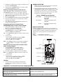
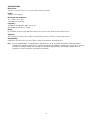
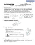
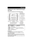
800-08932 5/11 Rev. A
5800ZBRIDGE
Z-Bridge Module
INSTALLATION AND SETUP GUIDE
GENERAL INFORMATION
5800ZBRIDGE is a wireless, intelligent energy
management device that provides an interface
between Z-Wave Modules and Honeywell LYNX
Security Systems and VISTA Control Panels that are
equipped with RF keypads.
POWER UP MODULE
1. Plug in 12VDC power supply, LED flashes
ORANGE 3 times and then goes out. (Refer to
Figure 2)
PROGRAMMING
Enroll 5800TM Code into Module
1. Press SW5 LEARN switch for 1 second and
release. LED will begin flashing ORANGE.
2. Disarm or Arm the control panel (with 5800TM
code turned on). The LED will stop flashing
ORANGE and the color will follow status of the
control panel.
Note: The 5800ZBridge is not compatible with the 5800TM or
5883H modules.
Features
• Automatically set back Z-Wave enabled
thermostat when security system is Armed
AWAY.
• Automatically turns lights off when security
system is Armed AWAY.
• Sends run command to Z-Wave enabled
thermostat when security system is Disarmed.
• Automatically turns lights on when security
system is Disarmed.
• Alarm Status light: Ready, Armed Away and Stay.
• Will function with any Z-Wave device
Note: The module will time out of program mode after 3
minutes if no TM code is enrolled.
Table 1 - 5800ZBRIDGE LED Indications
Indication
Flashing Red
Steady Red
Solid Green
Flashing Orange
MOUNTING
1. Determine the optimum mounting location taking
care to avoid damp locations. To maximize the
transmitter’s range, avoid mounting the device to
metal objects, if possible. The module should be
located a maximum of 6 feet from an unswitched
120VAC outlet.
2. Open the 5800ZBRIDGE case as shown in Figure
1.
3. Mount the 5800ZBRIDGE using the provided
screws. (Refer to Figure 2)
Meaning
Armed AWAY
Armed STAY
Ready
ALARM/Panic
Note: Following an alarm, the User Code must be entered
twice and the keypad must go to ready in order for the
Z-Bridge Module to release thermostat setback and/or
turn on lights.
Enroll (include) Devices in Z-Wave Modules into
5800ZBRIDGE module
1. Press the corresponding switch (SW1 through 4)
for 1 second and release for any combination of
four Thermostats or Lights. (Refer to Figure 2)
2. The 5800ZBRIDGE LED will begin flashing
Green.
3. Press button on the respective Z-Wave device to
learn (include) the device. The 5800ZBRIDGE
LED will stop flashing GREEN and return to
status of control panel.
4. Repeat for each Z-Wave device as applicable.
Note: The module will time out of program mode after 2
minutes if no Z-Wave device in enrolled (included).
Reset 5800ZBRIDGE Module
1. Disconnect the 12VDC power supply.
2. Press and hold SW5 LEARN switch and then plug
in 12VDC power supply. LED flashes Orange 5
times and then goes out.
3. Release switch SW5. TM code has been deleted
and 5800ZBRIDGE has been deleted (excluded)
from the Z-Wave network.
5800Z-002-V0
Figure 1. Opening the 5800ZBRIDGE
-1-
NORMAL OPERATION
1. When the Security System is armed or disarmed
it will operate as noted in Table 2.
4. Unplug the 12VDC power supply and plug it back
in to the 5800ZBRIDGE.
5. Program the 5800ZBRIDGE in accordance with
the PROGRAMMING section.
2. If the Security System has gone into alarm the
5800ZBRIDGE LED will flash ORANGE. To reset
the module you will need to clear the Alarm by
disarming the system two times (enter two OFF
sequences via the keypad or keyfob).
Deleting (excluding) Z-Wave modules/devices
Delete (exclude) Z-wave modules/devices from the
5800ZBRIDGE when they are no longer required.
1. Press and hold (5 seconds) the SW1, SW2, SW3 or
SW4 switch as applicable to remove a device.
2. Release the switch.
3. The 5800ZBRIDGE LED will begin flashing RED.
4. Press the Z-Wave device to allow host to delete
(exclude) the module.
5. The LED will stop flashing RED and return to
status of security panel.
Table 2 – ZBRIDGE System Operation
Include/Exclude/Receive Primary Role of
5800ZBRIDGE to/from another Z-Wave Network
1. Set another Z-Wave controller into Include,
Exclude, or Controller Shift mode.
2. Press and hold SW1 and SW2 on the
5800ZBRIDGE for 5 seconds, LED will blink
between GREEN and ORANGE.
Armed AWAY
=
Armed STAY
=
Disarm
=
Thermostat Set back/ Energy
Save mode
Lights OFF
Thermostat normal/run mode
Lights ON
Thermostat normal/run mode
Lights ON
MANUAL OPERATION
Connect a jumper wire between screw terminals on
the 5800ZBRIDGE. This will activate the device and
send the Z-Wave setback command. The LED will
indicate the system operation by illuminating as
follows:
RED
= Sent Setback command
GREEN = Sent Release Setback command
Note: The LED will blink until process finishes or times out (5
seconds).
3. If the process:
- is successful, the LED will turn GREEN
- times out, the LED stops blinking
- fails, the LED will turn RED
Note: If the Z-Bridge has been removed from a network it is
recommended the user/installer rest the Z-Bridge
device.
Relinquish (shift) Primary Role to another control
within a Z-Wave Network
1. Press and Hold SW3 and SW4 on the
5800ZBRIDGE for 5 Seconds, LED will
alternately blink RED and ORANGE.
2. Put other Z-Wave controller into Learn Mode
SW5
12 VDC
POWER SUPPLY
RECEPTACLE
Note: The LED will blink until process finishes or times out
(30 seconds).
SW1 to SW4
3. If the process:
- is successful, the LED will turn GREEN
- times out, the LED stops blinking
- fails, the LED will turn RED
TERMINALS
TESTING
1. Test each device by arming and disarming
security system. Refer to Table 2 for System
Operation.
MOUNTING
HOLES (2)
5800Z-001-V0
FIGURE 2. 5800ZBRIDGE
FREQUENTLY ASKED QUESTIONS AND TROUBLESHOOTING
Question
Answer
How many devices can the 5800ZBRIDGE control?
5800ZBRIDGE can control up to four (4) Z-Wave devices
When I press the first 5800ZBRIDGE button the light flashes
red one time and stops?
Unplug the unit and plug it back in.
After the System goes into alarm I entered the code but the
5800ZBRIDGE still blinks orange?
The System needs to have a green ready on the keypad, you
need to disarm the system again to clear the memory.
-2-
SPECIFICATIONS
Dimensions:
4.5" H x 2.75" W x 0.25" D (114.3 mm x 69.85 mm x 6.35 mm)
Power:
12VDC Power Supply
Environmental Conditions:
14° to 122°F (-10° to 50°C)
<90% RH (non-condensing)
Frequency
345 MHz (from 5800 Series TM Code receiver)
908.42 MHz (from Z-Wave controller)
Range
Up to 100 feet (30.48 m) using 5800 Series wireless devices and 75 feet (22.86 m) from Z-Wave devices.
Supports:
Any combination of up to four Z-Wave enabled thermostats or Z-Wave enabled light devices
Compatibility:
5800 Series Wireless TM code and Z-Wave enabled thermostats and light devices
Note: The Honeywell Z-Bridge is a certified Z-Wave controller and as can be operated in one Z-Wave network with Z-Wave
certified devices from other manufacturers. The different listening nodes within the network may act as repeaters regardless
of vendor. The Z-Bridge controls devices though use of the Basic Command Class, the Z-Bridge controller does not
respond too or map received basic command to any functions.
-3-
FCC and Industry Canada Statement
Federal Communications Commission (FCC) Part 15
The user shall not make any changes or modifications to the equipment unless authorized by the Installation Instructions or User's Manual. Unauthorized
changes or modifications could void the user's authority to operate the equipment.
CLASS B DIGITAL DEVICE STATEMENT
NOTE: This equipment has been tested and found to comply with the limits for a Class B digital device, pursuant to part 15 of the FCC Rules. These limits
are designed to provide reasonable protection against harmful interference in a residential installation. This equipment generates, uses and can radiate radio
frequency energy and, if not installed and used in accordance with the instructions, may cause harmful interference to radio communications. However, there
is no guarantee that interference will not occur in a particular installation. If this equipment does cause harmful interference to radio or television reception,
which can be determined by turning the equipment off and on, the user is encouraged to try to correct the interference by one or more of the following
measures:
•
•
•
•
Reorient or relocate the receiving antenna.
Increase the separation between the equipment and receiver.
Connect the equipment into an outlet on a circuit different from that to which the receiver is connected.
Consult the dealer or an experienced radio/TV technician for help.
This Class B digital apparatus complies with Canadian ICES-003.
Cet appareil numérique de la classe B est conforme à la norme NMB-003 du Canada.
FCC IC Statement
This device complies with Part 15 of FCC Rules and RSS 210 of Industry Canada. Operation is subject to the following two conditions: (1) This device may
not cause harmful interference, and (2) This device must accept any interference received, including interference that may cause undesired operation.
Cet appareil est conforme à la partie 15 des règles de la FCC & de RSS 210 des Industries Canada. Son fonctionnement est soumis aux conditions
suivantes: (1) Cet appareil ne doit pas causer d' interferences nuisibles. (2) Cet appareil doit accepter toute interference reçue y compris les interferences
causant une reception indésirable.
WARRANTY INFORMATION
For the latest warranty information, please go to:
www.honeywell.com/security/hsc/resources/wa
2 Corporate Center Drive, Suite 100
P.O. Box 9040, Melville, NY 11747
Copyright © 2011 Honeywell International Inc.
www.honeywell.com/security
Ê800-08932NŠ
800-08932 5/11 Rev. A