1
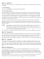
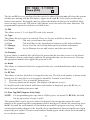
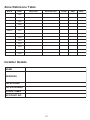
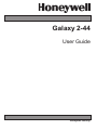
Galaxy 2-44 User Guide Honeywell Security Table of Contents Table of Contents .............................................................. iii Introduction ......................................................................................... 1 Controlling Your Alarm System .......................................................... 2 Users .................................................................................................................................... 2 Groups .................................................................................................................................. 2 Keypads ................................................................................................................................ 3 Prox Tags/Cards .................................................................................................................. 3 Wireless Keyfobs ................................................................................................................ 4 Setting the System — Full Set ............................................................4 Setting the System — Part or Night Set ............................................. 5 Setting with Faults ...............................................................................5 Cancelling System Setting ................................................................. 6 Unsetting .............................................................................................. 6 Cancelling an Alarm ............................................................................ 6 Alert Conditions ................................................................................... 6 Setting and Unsetting Groups ............................................................6 Setting and Unsetting Without Group Choice .................................................................... 6 Menu Access ........................................................................................ 7 Setting and Unsetting With Group Choice .......................................................................... 7 Menu 11 - Omit Zones .......................................................................................................... 8 Menu 12 - Timed Set ............................................................................................................ 8 Menu 13 - Part Set ............................................................................................................... 8 Menu 14 - Night Set .............................................................................................................. 8 Menu 15 - Chime .................................................................................................................. 8 Menu 21 - Zone Status ......................................................................................................... 8 Menu 22 - View Log ............................................................................................................. 9 Menu 23 - Display Version ................................................................................................... 9 Menu 24 - Print ..................................................................................................................... 9 Menu 31 - Walk Test .......................................................................................................... 10 Menu 32 - Output Test ........................................................................................................ 10 Menu 41 - Time/Date .......................................................................................................... 10 Menu 42 - Editing Users ..................................................................................................... 10 Menu 44 - Mobile Numbers ............................................................................................... 12 Menu 47 - Remote Access ................................................................................................ 12 Menu 48 - Level 3 Access ................................................................................................. 12 Zone Reference Table .......................................................................13 Installer Details ..................................................................................13 iii iv Introduction The Galaxy 2-44 is a programmable alarm control panel that will allow you to protect your home or business by providing secure and reliable intruder detection. The system can be fully tailored by your installer to operate in the most convenient way for your lifestyle or working practice. If there are any changes in your requirements, your installer will be able to make any necessary changes to the system configuration in order to continue to provide the best protection whilst maintaining ease of use. An alarm system will protect you best only when used correctly. Please take the time to read through these instructions carefully in order to get the best from your alarm system, and avoid false alarms. Remember: An alarm system will only protect against intruders if it is Set appropriately. Always remember to Full Set, Part Set or Night Set the system when applicable. WARNING: There are no user serviceable parts inside the alarm system component housings. Refer all servicing to qualified alarm service engineers. 1 Controlling Your Alarm System Users Each person who uses the system is described as a ‘User’ and can have their own unique identity, in the form of a PIN code, prox tag or wireless keyfob, or a combination of all 3. Different users can have a different level of access to the alarm system functions. All this can be set up in the user programming section described later. The control panel can be controlled in one of 3 ways: 1. By entering a PIN code at a keypad and pressing function buttons. 2. By presenting a Proximity (prox) tag to a prox reader. 3. By pressing a button on a special encrypted wireless keyfob. Although all of the above methods of control will allow the user to set and unset the system for day to day operation, the keypad is required to reset the system after an alarm or fault condition. The keypad is also used to access the menu structure where additional functions can be accessed such as: Viewing the event log Programming user codes Temporarily omitting zones from the system Groups On larger systems, it is often necessary to split the system into separate areas or ‘Groups’ that can be set and unset independently by different users. Group operation can only be set up by an installer. The Galaxy 2-44 can be split into 3 separately controllable groups. If your system has been set up with Group operation, look for the notes on Groups throughout this manual. 2 Keypads There are two types of keypad available as shown below but both work in a similar manner. The number buttons are for entering PIN codes and for changes options. The function keys down the side have the following use: A>: This scrolls forward in a list or menu and activates a FULL set. B<: This scrolls backwards in a list or menu and activates a PART or NIGHT set. ent: This saves a current setting or activates the currently displayed command. esc: This aborts an operation or escapes back out of a menu option. The default user PIN code is 1234. It is strongly recommended that this code be changed to something else as soon as possible. Choose a PIN code that you can remember easily but would be difficult for an intruder to guess. GALAXY 44 V1.0 08:58 TUE 22 NOV 1 A 2 PART FULL 1 2 3 A 4 5 6 B 7 8 9 ent * 0 # esc 4 B ent 7 6 TEST OMIT 8 0 * LOG ESCAPE Mk7 LCD Keypad NIGHT 5 CODE esc 3 9 CHIME # EASY SET 6160 Keypad Prox Tags/Cards GALAXY 44 V1.0 08:58 TUE 22 NOV Prox tags/cards are devices that contain a microchip that has a unique serial number. This number can be read by holding the tag/card in front of a prox reader. Prox tags/cards will allow you to set and unset the system only. The prox readers are usually built in to the case of a keypad and are identified by the prox symbol as shown: A 1 2 4 5 6 B 7 8 9 ent * 0 # esc 3 Setting/Unsetting Mk7 keyprox with a prox card 3 Wireless Keyfobs Keyfobs are portable controllers that can be attached to a key ring. They will allow you to Set and Unset the system by a single press of a button and can sometimes be programmed with additional functions. Because they operate by radio, they can be used anywhere around the premises provided that they are within range of the installed radio receiver. NOTE: Labels are provided to place over the buttons to indicate the function. Setting the System — Full Set To set the system, make sure all doors are closed and windows are secure. The system cannot be set if there has previously been an alarm which has not been reset. To set the entire system: Keypad: Type your PIN code then press [A] Wireless Keyfob: Press [ON] button Prox Tag: Hold the tag in front of the prox symbol for 3 seconds The exit timer will begin and there will be a constant tone. Leave by the agreed exit route and close the door. When the exit timer expires, there will be a 5 second settle period and then two beeps will confirm the completion of setting. FULL SET 060 NOTE: Display not shown when using wireless keyfobs to set the system. If you hear a rapid beeping sound, the system cannot set as there are open zones. The keypad will show which zones are open. Open Zone 1044 The setting procedure can be cancelled at any time during the exit time by pressing the esc key on the keypad, the [OFF] button on the keyfob or placing the tag back in front of the prox symbol. 4 Setting the System — Part or Night Set Part and Night setting are similar to Full setting but leave off certain detectors as agreed with your installer. Additionally, the system can be programmed by the installer not to give any exit timer tones during the setting period (silent set). To Part or Night set: Keypad: Type your PIN code then press [B]. Press [1] Part Set or Press [2] Night Set. Wireless Keyfob: Press the [Lower Left] button (Part) or Press the [Lower Right] button (Night). Prox Tag: Use the keypad for Part or Night setting. The tag will only Full Set. A 30 second exit timer will begin. Leave the protected area by the agreed route. A double beep at the end of the exit time will confirm setting. PART SET 030 NOTE: Display not shown when using wireless fobs to set the system. Setting with Faults Normally, if there is a fault of any kind on the system, setting will not be permitted until the fault is rectified. However, depending on the set-up of your system and the level of your user access, it may be possible override a fault and proceed with the setting procedure. If there are faults present when you try to set via the keypad, the following typical display will be shown: Fault Override 03 Event(s)> Use the cursor keys to scroll through the faults. If you are able to override them, the bottom row will show the message ENT to continue>. AC Fail ENT to Continue Pressing the ent key at this point will override the fault for one set period only and allow the system to set. If there is more than one fault, this process is repeated for each fault. 5 Cancelling System Setting The Full, Part and Night setting routines can be cancelled, before the system sets, by pressing the esc key on the keypad used to begin the setting routine. To cancel the setting routine on another keypad, type in your user PIN code and press A> or ent. Unsetting To unset the system, enter the protected area by the agreed route. A timed entry period will begin and a pulsed tone will sound. Keypad: Type your user code then press [ent]*. Wireless Keyfob: Press the [OFF] button. Prox Tag: Hold the tag in front of the prox symbol. * NOTE: Unsetting using a keypad may not be possible on DD243 compliant systems. Cancelling an Alarm The process for cancelling an alarm is similar to unsetting the system. However, if a wireless keyfob or prox tag has been used, the alarms must be viewed on a keypad by typing in a user code and following the on-screen instructions. Only certain users are able to reset the system following an alarm condition. You installer will inform you which users have this ability. Alert Conditions If a fault condition occurs when the system is unset, an ‘Alert!’ message will be shown on the keypad accompanied by an intermittent beep. If this occurs, you should go to the nearest keypad and type in your PIN code and press ent. The keypad display will show what has happened. The scroll keys A> and B< should be used to scroll through the message screens. If the condition has cleared, pressing ent or esc will reset the fault condition. A fault condition cannot be reset if it has not cleared or if it has not been viewed by a user. If you cannot clear the fault condition yourself, always call the installer for advice. Setting and Unsetting Groups It is possible to split the alarm system into separate areas or ‘Groups’ that can be set and unset independently. Different users can be given access to only certain groups, or to all groups. Also, individual users can be given the option of simply setting and unsetting all groups assigned to their code or choosing which groups to set or unset each time. Setting and Unsetting Without Group Choice When a user with access to multiple Groups, but no group choice, wants to set or unset, they should follow the standard procedures on the previous pages. 6 Setting and Unsetting With Group Choice With group choice, setting is initiated as normal, using a code, tag or fob. However, a choice of groups will then be displayed along with the current status of each group. The status can be changed for each group by pressing the appropriate number button and the display will cycle through the possible options. SET GROUPS 123 SUU S = SET U = UNSET Pressing the ent key will implement the status shown. If a code, keyfob or tag is used while an entry timer is running or an alarm is in progress, the group that is active will be unset immediately, without any status needing to be changed on the keypad. Menu Access To access the other functions of the system, users can enter the menu mode by typing their PIN code and pressing the ent button. This will display the first menu item after showing system status for 5 seconds. 10 = Setting [ent] to Select Users can then navigate around the menu using the scroll keys, ent key and esc key, or they can jump to any specific menu item directly by typing the number of the item. An overview of all the accessible functions is shown below. Not all users will be able to access all of the functions. This will depend on their ‘user type’ that is set up in menu 42. 10 = Setting 20 = Display 30 = Test 40 = Modify 11 = Omit Zones 21 = Zone Status 31 = Walk Test 41 = Time/Date 12 = Timed Set 22 = View Log 32 = Output Test 42 = Users 13 = Part Set 23 = System Version 44 = Mobile Nos 14 = Night Set 24 = Print 47 = Remote Access 15 = Chime 48 = Level 3 Access Table 1. Menu Access The function of each menu item is described in the following pages. 7 Menu 11 - Omit Zones This function allows a user to temporarily disable a detection zone from the system (for example, to disable a movement detector when a dog is left in the house). Zone omits last for one set period only and automatically switch off when the system is unset. On entering the menu option, the first omittable zone is displayed. The A> and B< scroll keys can be used to select the different zones in turn. To omit a particular zone, scroll to the zone so that it is displayed on screen. Press the # key and the message in the bottom left corner will change to ‘Omitted’. Select other zones as required in a similar way. When all zones have been selected as required, press ent to begin setting with the omitted zones, or esc to escape back out and save the omitted zones for setting later. Menu 12 - Timed Set This option initiates the timed full setting routine, identical to typing a PIN code and pressing the A> key. Menu 13 - Part Set This menu option initiates the timed Part Set routine as described earlier. Menu 14 - Night Set This menu option initiates the timed Night Set routine as described earlier. Menu 15 - Chime This menu option allows one or more zones to be put into Chime mode. When chime mode is enabled for a zone, the internal sounders will beep twice each time the detector on that zone is activated. This function can be useful, for example, in a shop to indicate when a customer has come through the front door. Menu 21 - Zone Status This menu option is used to show the status of each individual detection zone on the system. On entering the option, the first system zone will be displayed as shown: On the top row, the zone address is shown along with the zone function which toggles with the current status (open, closed, etc). NOTE: If groups are enabled, the group will be shown. status 1001 ZONE1 function CLOSED 1001 ZONE1 group FINAL 1001G1 ZONE1 CLOSED On the bottom row, the description of the zone is shown to aid identification. Using the A> and B< scroll keys, any of the zones on the system can be displayed. Additionally, pressing the # key will show additional diagnostic information for that zone. This may be required for fault finding when talking to the alarm installation company by phone. 8 Menu 22 - View Log This option displays the system event log. The log records all events that occur in the system and is vital for tracing the chain of events during a break-in or when trying to trace a fault. On entering the option, the most recent event is displayed on screen in the following format: Event Time Date 09:51 1021+ 01/08/04 Intruder Event Source Event Type Pressing the B< key will jump backwards in time by one event. Pressing the A> key will jump forwards by one event. Holding the scroll keys down will jump by one day at a time (Mk7 keypad only) with the date only displayed whilst scrolling. Additional information about each event can be shown, where available, by pressing the # key. NOTE: If groups are enabled, you can select which groups to view before entering the log. Menu 23 - Display Version This menu option simply displays the software version number of the system. Menu 24 - Print This option allows system settings to be printed if a printer is connected to the system. If no printer is connected, it has no effect. On selecting the option, there is a sub-menu of 4 options, which chose what is to be printed. The options are as follows: 1 = Codes Prints a list of all users on the system. 2 = Zones Prints a list of all zones on the system. 3 = Log Prints the event log. 4 = All Prints options 1, 2 and 3. On selecting an option by pressing the appropriate key, a message will display that printing is in progress. 9 Menu 31 - Walk Test This menu allows the zones to be manually tested. There are two sub-options to this function as follows: 1 = Test all Zones This puts all omittable zones into walk test immediately. 2 = Test Selected Zones This allows the user to select specific zones to be put into test. On selecting the option, the first zone is displayed with the zone number and description on the top row. On the bottom row, the test status is displayed. If the # key is pressed that zone is selected for test and the message in the lower corner displays as appropriate. Each zone can be toggled on or off by pressing the # key. When all zones have been selected for test as required, press the ent key to start the test, or the esc key to abort. Once the test has been started, any activation of a detector on test will cause the internal sounders to beep twice. The zone number and description will also display on the keypad. When more than one zone is activated at the same time, the scroll keys can be used to view all the active zones. NOTE: For wireless movement detectors, always ensure that the detectors on test are left undisturbed for 3 minutes before activating the walk test. This is because the wireless movement detectors will enter a sleep mode after being activated in order to save battery life during repeated activations. Press the esc key to end the walk test. All walk-tested zones will be recorded in the event log. Menu 32 - Output Test This menu option allows the external bell and strobe to be tested. There are two sub-options that select between the bell and strobe. Select the appropriate device and press ent. This will take the user to the status display to show the current condition of the device (on or off). Pressing the ent key will toggle the status on or off to test the device. Press esc to end the test. Menu 41 - Time/Date This option allows the system time and date to be set. On entering this menu, there are two sub options, A=Time and B=date. Pressing the A or B keys allows the time or date as appropriate to be set by directly entering the new value. Time is entered in 24 hour notation and the date is entered in 6-digit notation, with two digits each for the day of the month, month and the year. Menu 42 - Editing Users The system can have up to 24 users (user 24 is the default master user). Each user can be assigned a PIN code, a Wireless keyfob and/or a prox tag. They are also assigned an access type, which dictates what the user can and can’t do. Menu 42 allows users to alter their own PIN code and allows Master users to add and remove users from the system, as well as manage users access rights. On entering menu 42, there is a sub-menu, 1=Users. On entering the sub-menu, the first user is displayed on the screen (normal users can only see their own user programming). 10 0 1 User 1 * 1 2 3 4 User(L2) The A> and B< keys are used to select the user to be edited. Pressing ent will show the options for that user, starting with the PIN option. Again, the A> and B< keys can be used to move between the options. Pressing the ent key allows the displayed option to be modified. Most users can only access the PIN option. Only Master users can access the other functions. The programmable options for each user are listed below: 1 = PIN This allows a new 4, 5, or 6 digit PIN code to be entered. 2 = Type This allows the user type to be selected. There are 4 types available to choose from: 0 = Cleaner Can only set and unset the system 1 = User Can do all day-to-day operation but cannot override fault conditions 2 = Manager As per User but can override faults and reset alarms and tampers 3 = Master As per Manager but can add, remove and alter user codes. 3 = Group(s) If group choice is enabled, this will allow the groups that the user has access to to be altered. The numbers shown on the display indicate the groups that the user has access to. Pressing the appropriate number key toggles the group on or off. 4 = Name This allows a 6-character label to be assigned to the user, to aid identification when viewing the event log. 5 = RF Fob This allows a wireless keyfob to be assigned to the user. The fob serial number is shown in the bottom row. If a new fob is to be assigned it should be ‘learned’ in as follows: 1. Press the star (*) key to start the learn process. 2. Press any button on the keyfob. The display will indicate success. If a keyfob needs to be deleted, while the serial number is displayed, press the B< key to delete the serial number then press ent. 6 = Prox Tag (Mk7 Keyprox Units Only) NOTE: For programming prox tags onto a 6160 keyprox, use menu 5 = RF Fob, but hold the tag up in place of steps 1 and 2. This option allows a prox tag to be entered or deleted. On entering the option, the serial number of the current tag that is programmed will be displayed. To delete the current tag, press the B< key until the serial number is cleared then press ent. To program a new tag, clear any current serial number then press the 1 and A> keys simultaneously then present the new tag in front of the prox symbol. The new serial number should appear on the screen. Press the ent key to save the new number. 11 7 = Duress The duress function, when enabled, forces a panic signal to be sent to the monitoring station each time the user PIN, fob or tag is used. Duress codes should only be used in emergency situations when there is a threat to life. Menu 44 - Mobile Numbers This option allows the SMS text messaging feature to be altered. The system can send event messages to up to 3 mobile phones by text messaging. The type of events that are sent can be individually selected for each of the three mobile phone numbers. In this menu option, there are 3 sub-menus, one for each of the mobile phones. On selecting a particular mobile (1 to 3) and pressing ent, there are a further two sub-options as follows: 1 = Mobile numbers This allows the actual mobile number to be entered. The number is entered directly by typing the number in directly at the keypad. A number can be deleted or corrected by repeatedly pressing the B< key. The number is saved by pressing ent. 2 = Message type This allows the kind of events that are sent to this mobile number. There are 4 options: 1 = Alarm events Just sends alarm activations. 2 = Alarm & set events Sends alarms and all set & unset events. 3 = Alarm & fault Sends all alarm events and fault conditions but not set & unset events. 4 = All events Sends all of the above events as and when they occur. Menu 47 - Remote Access This menu option allows the user to initiate a remote service call when required by the installation company. The remote servicing function allows the Galaxy alarm system to be remotely monitored and reprogrammed over the phone line, by way of a modem connection or GSM to a computer at the alarm installer’s premises at a predetermined phone number. This option should only be used when required by your installation company. Menu 48 - Level 3 Access This option is used to authorise access by an installation or service engineer. An engineer has a special access code that is only enabled when an appropriate user accesses this menu option and enables level 3 (installer) access by pressing the 1 key followed by ent. The engineer then has 5 minutes to enter his own code. 12 Zone Reference Table RIO 00 ZONE FUNCTION DESCRIPTION 1001 1002 1003 1004 RIO 01 1011 1012 1013 1014 1015 1016 1017 1018 Installer Details NAME ADDRESS TELEPHONE OFFICE HOURS OTHER TIMES ACCOUNT NO. 13 CHIME OMIT PART © Copyright Honeywell Security IU1-0032 Rev 1 14