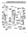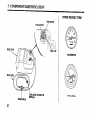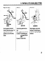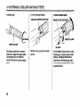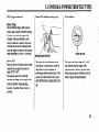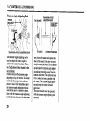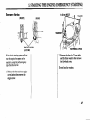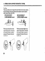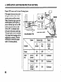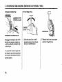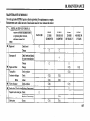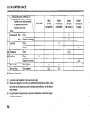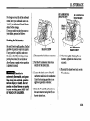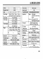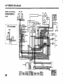
1
BF40A/50A
Owner’s
Manual
HONDA MOTOR CO., LTD. TOKYO, JAPAN
31ZW4603
00X31-ZW4-6030
EM
200.2002.08
PRINTED IN U.S.A.
CC
© HONDA MOTOR CO., LTD. 1999
2000
The engine exhaust from this product
contains chemicals known to the State
of California to cause cancer, birth
defects or other reproductive harm.
Keep this owner’s manual handy, so you can refer to it at any time. This owner’s manual is
considered a permanent part of the outboard motor and should remain with the outboard
motor if resold.
The information and
approval for printing.
change specifications
obligation whatever.
permission.
specifications included in this publication were in effect at the time of
Honda Motor Co., Ltd. reserves the right, however, to discontinue or
or design at any time without notice and without incurring any
No part of this publication may be reproduced without written
INTRODUCTION
Congratulations on your selection of a
Honda outboard motor. We are certain
you will be pleased with your purchase
of one of the finest outboard motors on
the market.
We want to help you get the best results
from your new outboard motor and to
operate it safely. This manual contains
the information on how to do that;
please read it carefully.
As you read this manual, you will find
information preceded by a -1
symbol. That information is intended to
help you avoid damage to your outboard
motor, other property, or the environment.
We suggest you read the warranty policy
to fully understand its coverage and your
responsibilities of ownership. The
warranty policy is a separate document
that should have been given to you by
your dealer.
When your outboard motor needs
scheduled maintenance, keep in mind
that your Honda marine dealer is
specially trained in servicing Honda
outboard motors. Your Honda marine
dealer is dedicated to your satisfaction
and will be pleased to answer your
questions and concerns.
0 1999 Honda Motor Co., Ltd.
All Right Reserved
1
INTRODUCTION
A FEW WORDS ABOUT
SAFETY
Your safety and the safety of others are
very important. And using this outboard
motor safely is an important responsibility.
You will find important safety information a variety of forms, including:
l
Safety Labels - on the outboard motor.
l
Safety Meswges - preceded by a safety alert symbol &J and one of three signal
words, DANGER, WARNING,
or CAUTION.
These signal word’s mean:
To help you make informed decisions
about safety, we have provided operating procedures and other information on
labels and in this manual. This information alerts you to potential hazards that
could hurt you or others.
Of course, it is not practical or possible
to warn you about all the hazards
associated with operating or maintaining
an outboard motor. You must use your
own good judgment.
You WILL be KILLED or SERIOUSLY
HURT if you don’t follow instructions.
You CAN be KILLED or SERIOUSLY
HURT if you don’t follow instructions.
l
Safety Headings - such as IMPORTANT
l
Safety Section - such as OUTBOARD MOTOR SAFETY.
l
Instructions - how to use this outboard motor correctly and safely.
SAFETY INFORMATION.
This entire book is filled with important safety information -please
2
read it carefully.
TYPES OF HONDA
BF40AhOA
OUTBOARD
MOTORS
It may be necessary to refer to this chart for reference purposes when reading this manual.
Model
BWOA
BFSOA
TYPE CODE (example)
L
R T
T = Power Trim/l%t
R = Remote Control
H = Tiller Handle
X = Extra Long Shaft
L = Long Shaft
TTT
3
i
IDENTIFICATION
RIGHT STERN BRACKET
PRODUCT IDEilTIFICATION
NUMBERS
, /---A
NUMBER
Record the Product Identification
Number (P.I.N.) and the Engine Serial
Number for your reference. Refer to the
Product Identification Number when
ordering parts, and when making
technical or warranty inquiries (see page
107).
ENGINE SERIAL NUMBER
‘The Product Identification Number is
stampedon a plate and attached to the
right stem bracket. The Engine Serial
Number is stampedon the cylinder
block under the starter motor which is
located in the front of the engine.
Product identification number:
Engine serial number:
4
CONTENTS
1. OUTBOARD MOTOR SAFETY
IMPORTANT SAFETY INFORMATION.. .........
SAFETY LABEL LOCATIONS ..........................
............................
2. COMPONENT IDENTIFICATION
3. CONTROLS
TILLER HANDLE TYPE
Engine Start Button ...............................................
Shift Lever .............................................................
Choke Knob ...........................................................
Throttle Grip ..........................................................
Throttle Opening Indicator ....................................
Throttle Friction Knob ...........................................
Engine Stop Switch ...............................................
Emergency Stop Switch Lanyard ..........................
Oil Pressure Indicator Light ..................................
Overheat Indicator Light .......................................
REMOTE CONTROL TYPE
Remote Control Lever ...........................................
Neutral Release Lever ...........................................
Ignition Switch ......................................................
Emergency Stop Switch Lanyard ..........................
Choke/Fast Idle Lever ...........................................
Manual Choke Knob.. ............................................
Oil Pressure Indicator Light/Buzzer.. ....................
Overheat Indicator Light/Buzzer.. .........................
POWER TRIM/TILT TYPE
Power Trimflilt Switch .........................................
Power Tilt Switch (motor pan) ..............................
Trim Meter.. ...........................................................
7
9
10
13
13
13
14
14
14
15
15
16
16
17
18
18
19
20
20
21
21
Tachometer ............................................................
Manual Relief Valve.. ............................................
GAS ASSISTED TILT TYPE
Tilt Lever ...............................................................
CONTROLS (COMMON)
Tilt Lock Lever.. ....................................................
Trim Tab ................................................................
Anode Metal ..........................................................
Cooling System Indicator ......................................
Water Intakes .........................................................
Transom Angle Adjusting Rod.. ............................
Fuel Cap/Gauge/Vent Knob ..................................
Over-Rev Limiter ..................................................
4. PRE-OPERATION CHECKS
Engine Cover Removal/Installation ......................
Engine Oil ..............................................................
Fuel Level ..............................................................
Fuel Recommendations .........................................
Oxygenated Fuels ..................................................
Propeller and Cotter Pin ........................................
Steering Friction Adjustment (common) ...............
Remote Control Friction Adjustment ....................
Other Checks
Stern Bracket.. .....................................................
Tool Kit ...............................................................
Anodes .............................................................. ..
5. STARTING THE ENGINE
Fuel Tank and Vent Knob .....................................
l
l
l
22
23
23
24
24
25
25
25
26
27
27
28
29
29
30
31
32
33
34
35
36
36
37
37
37
38
5
CONTENTS
Fuel Line Connection ............................................ 38
STARTING THE ENGINE (TILLER HANDLE TYPE). .. 40
STARTINGTHE ENGINE(REMOTECONTROLTYPE)... 44
Emergency Starting ............................................... 47
Troubleshooting Starting Problems .......................
6. OPERATION
Break-in Procedure.. ...................................................
TILLER HANDLE TYPE
Gear Shifting .........................................................
Steering ..................................................................
Cruising .................................................................
REMOTE CONTROL TYPE
Gear Shifting .........................................................
Cruising .................................................................
Tilting Motor
GAS ASSISTED TILT TYPE.. .............................
POWER TRIM/TILT TYPE .................................
POWER TRIM/TILT TYPE
Trim Meter.. ...........................................................
Power Tilt Switch (Motor Pan) .............................
Manual Relief Valve.. ............................................
Tilt Lock Lever ......................................................
Trim Tab Adjustment .................................................
MOTOR PROTECTION SYSTEM
Engine Oil Pressureand Overheat Warning System.. ..
Over-Rev Limiter ..................................................
Power Trim Warning System ................................
Anodes ...................................................................
Shallow Water Operation ......................................
6
52
53
54
55
55
57
58
59
62
64
65
65
66
67
68
70
70
71
72
High Altitude Operation ........................................ 73
7. STOPPING THE ENGINE
TILLER HANDLE TYPE ..................................... 74
REMOTE CONTROL TYPE.. .............................. 76
8. TRANSPORTING ..................................................... 77
9. CLEANING AND FLUSHING ................................. 78
10. MAINTENANCE.. ..................................................... 80
THE IMPORTANCE OF MAINTENANCE.. ...... 80
MAINTENANCE
SAFETY.. ................................ 80
EMISSION CONTROL SYSTEM INFORMATION ... 81
Tool Kit and Spare Parts.. ...................................... 84
MAINTENANCE
SCHEDULE ............................ 85
Engine Oil .............................................................. 87
Gear Oil ................................................................. 89
Spark Plugs ............................................................ 9 1
Battery (not included) ............................................ 92
Lubrication ............................................................ 93
Engine Fuel Filter .................................................. 94
Fuel Tank and Filter .............................................. 96
Fuse Replacement .................................................. 97
Propeller ................................................................ 98
Submerged Motor.. ................................................ 99
1I. STORAGE ................................................................. 101
................. ............................ 103
12. TROUBLESHOOTING
13. SPECIFICATIONS .................................................... 105
14. WARRANTY SERVICE ........................................... 107
15. WIRING DIAGRAM ................................................. 108
16. INDEX ....................................................................... 111
1. OUTBOARD
IMPORTANT SAFETY
INFORMATION
Operator Responsibility
l
Honda BF4OA and BFSOA outboard
motors are designed for use with boats
that have a suitable manufacturer’s
power recommendation, and other uses
can result in injury to the operator or
damage to the outboard motor and other
property.
Most accidents can be prevented if you
follow all instructions in this manual and
on the outboard motor. The most
common hazards are discussed below,
along with the best way to protect
yourself and others.
l
l
l
It is the operator’s responsibility to
provide the necessary safeguards to
protect people and property. Know
how to stop the engine quickly in
case of emergency. Understand the
use of all controls.
Stop the engine immediately if
anyone falls overboard, and do not
run the engine while the boat is near
anyone in the water.
Always stop the engine if you must
leave the controls for any reason.
Attach the emergency stop switch
lanyard securely to the operator.
l
l
l
l
l
l
l
M;OTOR SAFETY
Always wear a PFD (Personal
Flotation Device) while on the boat.
Familiarize yourself with all laws and
regulations relating to boating and the
use of outboard motors.
Be sure that anyone who operates the
outboard motor receives proper
instruction.
Be sure the outboard motor is
properly mounted on the boat.
Do not remove the engine cover
while the engine is running.
Do not attempt to modify the
outboard motor.
Do not remove any labels, covers, or
safety devices; they are installed for
your safety.
7
1. OUTBOARD
MOTOR SAFETY
Refuel With Care
l
l
l
l
Gasoline is extremely flammable, and
gasoline vapor can explode. Refuel
outdoors, in a well-ventilated area,
with the engine stopped. Never
smoke near gasoline, and keep other
flames and sparks away.
Carbon Monoxide Hazard
Exhaust gas contains poisonous carbon
monoxide. Avoid inhalation of exhaust
gas. Never run the engine in a closed
garage or confined area.
Remove any portable fuel tank from
the boat for refueling. Keep the
portable fuel tank away from the
battery or other potential spark
sources.
Refuel carefully to avoid spilling
fuel. Avoid overfilling the fuel tank.
After refueling, tighten the filler cap
securely. If any fuel is spilled, make
sure the area is dry before starting the
engine.
.
1. OUTBOARD
SAFETY LABEL LOCATIONS
These labels are in the locations shown.
They warn you of potential hazards that
could seriously injure you. Read these
labels carefully.
MOTOR
SAFETY
GASOLINE&g:
FLAMMABLE
DANGEROUS
GASOL
I NE
RHINE fRou WI fOR fllllffi
IOlml~lb]
INFLAIAMABLE
DANGEREUX
GAZOL
SllllR al Miw fulRmIff
I NE
lE RElWEIPhU
2. COMPONENT
THROTTLE
TILLER
HANDLE
\
IDENTIFICATION
(TILLER
HANDLE
TYPE)
GRIP
I
1
x
I
FUEL LINE
CONNECT-C )R
I
/
ENGINE COVER
OIL FILLER
CAP
OIL LEVEL
DIPSTICK
GEAR SHIFT LEVER
OIL PRESSURE INDICATOR
I
\
/
/
r
\
\ \ t---+1
FRICTION
LIGHT
OVERHEAT
INDICATOR
LIGHT
/
ENGINE
KNOB
TRANSOM&
ADJUSTING
/I
A
NTICA-
---VITATION
TiLT LEVER
W type)
WATER
LEVEL
Y
PLUG/
WASH PLUG
(Flush plug)
GEAR OIL DRAIN
10
(Al YODE METAL)
\
A 1 ICT
EXHr.,,.
PROPELLER
PLUG
.\
DC,RT
(optional)
INTAKE
STOP SWITCH
CLIP
I
\
SPARE EMERGENCY
STOP SWITCH CLIP
\
-_ _-EMBR( ‘;ENCY
STOP SWITCH
LANYA .RD
2. COMPONENT
ENGINE
COVER
POWER TILT
SWITCH
(except LR type)
FUEL LINE
CONNYCTOR
IDENTIFICATION
OIL FILLER
(REMOTE
CONTROL
TYPE)
CAP
KNOB
NEUTRAL
RELEASE LEVER
POWER TRIWILT
SWITCH
\
/
OIL PRESSURE
INDICATOR
v VERHEAT
INDICATOR
ra
a,
HT
TILT LEVER
(LR type)
COOLING
SYSTEM
INDICATOR
SPARE EMERGENCY
STOP SWITCH CLIP
ACCESS COVER
BUZZER
(inside of the box)
VITATION
LEVEL PLUG
DRAIN PLUG
\
\
PROPELLER
WASH PLUG
(Flush plug)
(optional)
\
WATER
SWITCH
INTAKE
LANYARD
I EMERGENCY
EMERGENCY STOP igNG;kSTOp
SWITCH CLIP
11
2. COMPONENT
IDENTIFICATION
POWER TRIM/TILT TYPES
FUEL GAUGE
VENT KNOB
/
FUEL
TACHOMETER
FUEL
I
PRIMER BULB
FtiEL HOSE CONNECTOR
(FEMALE)
TRIM METER
3. CONTROLS
R
(reverse)
N
ENt-bF, START
BUTTON
Move the gearshift lever to the N
(neutra1) position before starting. The
engine will not start unless the
gearshift lever is in the N (neutral)
position.
HANDLE
TYPE)
Choke Knob
Shift Lever
Engine Start Button
(TILLER
(revtse)
N
SHIFI- LEVER
There are three gearshift lever positions.
F (forward): The boat moves forward.
N (neutral): The transmission gears
are disengaged from the
engine.
R (reverse): The boat reverses.
CHOKiZ KNOB
When the engine is cold, pull the
choke knob. A rich fuel mixture is
provided to the engine by pulling the
choke knob.
13
,3. CONTROLS
(TILLER
HANDLE
Throttle OpeningIndicator
Throttle Grip
THRO’ITLE
THROTTLE
TYPE)
OPENING INDICATOR
Throttle Friction Knob
THROTI’LE
FRICTION
KN
GRIP
RELEASE
‘lItm the grip clockwise or counterclockwise to adjust the engine speed.
Turning the grip in the direction
shown by the arrow increases engine
speed.
14
The label on the grip indicates throttle
opening.
Use the throttle fiction knob to set the
throttle grip at a certain position while
cruising. Turning the friction knob
clockwise setsthe throttle grip, and it
is reieased by turning the friction knob
counterclockwise.
3. CONTROLS
Engine Stop Switch
Emergency Stop Switch Lanyard
EMERGENCY
HANDLE
TYPE)
ENGINE STOP
SWITCH
_
STOP SWITCH CLIP
EMERGENCY
ENGINE STOP SVi’ITCH
Push the engine stop switch to stop the
engine.
(TILLER
The emergency stop switch lanyard is
provided to stop the engine immediately in the event the operator should
fall overboard or away from the controls.
STOP SWITCH LANYARD
Attach the emergency stop switch lanyard securely to the operator when
operating the outboard motor.
The emergencystop switch clip must
be engagedwith the engine stop
switch or the engine will not start.
When the emergencystop switch clip
becomesdisengagedfrom the engine
stop switch, the engine will stop immediately.
15
3. CONTROLS
(TILLER
SPARE EMERGENCY
,STOP SWITCH CLIP
HANDLE
TYPE)
Oil Pressure Indicator Light
I
OIL PRESSURE INDICATOR
A spare emergency stop switch clip is
provided near the engine stop switch.
16
LIGHT
The green oil pressure indicator light
is normally ON when the outboard
motor is running.
When the engine oil level is low or the
engine lubrication system is faulty, the
green oil pressure indicator light turns
OFF and the engine speed decreases
gradually.
Overheat Indicator Light
OVERHEAT
INDICATOR
LIGHT
When the engine cooling system is
faulty, the red overheat indicator light
turns ON and the engine speed
decreasesgradually.
3. CONTROLS
(REMOTE
CONTROL
TYPE)
Remote Control Lever
a-”
THROTTLE
NEUTRAL
IEVERSE)
0
RELEASE
The remote control lever controls gear
selection and throttle opening positions.
It is necessaryto pull up the neutral
release lever to operate the remote
control lever.
‘ER
REMOTE CONTROL LEVER
F (forward):
Moving the lever to the F position
(approximately 30’ from the N
position) will engagethe forward
gear. Moving the lever beyond
the F position will increasethe
throttle opening and the boat forward speed.
R (reverse):
Moving the lever to the R position
(approximately 30’ from the N
position) will engagethe reverse
gear.Moving the lever beyond the R
position will increasethe throttle
opening and the boat reversespeed.
N (neutral):
The transmission gearsare disengaged.
17
3. CONTROLS
(REMOTE
Neutral ReleaseLever
CONTROL
TYPE)
Ignition Switch
START
ON
H
ON
To run the engiie after starting (the
battery will discharge if the key is
left in this position with the engine
not running).
OFF
The neutral release lever is on the
remote control lever to prevent an
accidental gear engagement.
The remote control box is equipped
The remote control lever will not
engage forward or reverse gear unless
the neutral release lever is pulled up.
START
18
with a key type ignition switch.
Key positions:
To activate the starter motor and start
the engine. (rhe remote control lever
must be in the neutral position)
To stop the engine (IGNITION
OFF).
To prevent the battery from discharging, keep the key in the OFF
position when the engine is not running.
3. CONTROLS (REMOTE CONTROL TYPE)
Emergency Stop Switch Lanyard
E
S
The emergency stop switch lanyard is
provided to stop the engine immediately in the event the operator should
fall overboard or away from the controls.
The emergency stop switch clip must
be engaged with the emergency engine
stop switch or the engine will not start.
When the emergency stop switch clip
becomes disengaged from the emergency engine stop switch the engine
will stop immediately.
SWITCH LANYARD
The emergency engine stop switch
should not he used to normally stop
the engine. Use the ignition switch to
normally stop the engine.
SPAkE EMERGENCY
STOP SWITCH CLIP
A spare emergency stop switch clip is
provided on the remote control box.
Attach the emergency stop switch lanyard securely to the operator when
operating the outboard motor.
19
3. CONTROLS
Choke/Fast Idle Lever
(REMOTE
CONTROL
TYPE)
Manual Choke Knob
N
(neutral)
f-l
CHOKE
XIMUM
FAST
IDLE
EST IPOSWION
CHOKWFAST
The choke/fast idle lever provides two
functions:
1. Electric choke solenoid activation
for easy engine start up.
2. Engine fast idle.
The choke/fast idle lever will not
move unless the remote control lever
is in the N (neutral) position.
Conversely, the remote control lever
will not move unless the choke/fast
idle lever is in the lowest position.
20
IDLE LEVER
Lift and hold the choke/fastidle lever
up fully, this will provide a rich fuel
mixture.
Gradually lower the choke/fastidle
lever to the lowest position to disengage
the choke and lower the idle speed
CHOKE KNOB
A manual choke knob is provided on
the right side of the motor which can
be used in the event the battery is discharged. Pull the manual choke knob,
and a rich fuel mixture will be provided to the engine.
3. CONTROLS
(REMOTE
Oil Pressure Indicator Light/Buzzer
Overheat Indicator Light/Buzzer
The green oil pressure indicator light
turns OFF and the buzzer sounds
when the oil level is low and/or the
engine lubrication system is faulty.
The engine speed slows down gradually-
The red overheat indicator light turns
ON and the buzzer sounds when the
engine cooling system is faulty. The
engine speed slows down gradually.
CONTROL
TYPE)
. 21
3. CONTROLS
(POWER TRIM/TILT
TYPE)
Power Trim/Tilt Switch
Power Trim
Pressthe power hn/tilt switch on the
remote control lever (remote control type)
to adjust the motor trim angle of 00 to 20’
to maintain proper boat mm. The power
trim/tilt switch located on the remote
control lever (remote control type) can be
operated while the boat is under way or
while stopped.
By using the power trim/tilt switch the
operator can change the trim angle of the
motor to achieve maximum boat acceleration, speed, stability and maintain
optimum fuel consumption.
Power Tilt
Press the power trim/tilt switch on the
remote control lever (remote control type)
to adjust the motor tilt angle of 20” to 60”.
By using the power trim/tilt switch the
operator can change the tilt angle of the
motor for shallow water operation,
beaching, launching from a trailer, or
mooring.
22
SWITCH
-CONTROL
LEVER
(remotecontrol type)
On the tiller handle type, the power
trim/tilt switch is the optional part. The
power trim/tilt switch is available on
your authorized Honda Marine dealer.
-1
Excessive trim/tilt angle
during operation can cause the
propeller to raise out of the water and
cause propeller ventilation and engine
over-revving. Excessive trim/tilt angle
can also damage the water pump.
3. CONTROLS
XRTA type outboard
Power Tilt Switch (motor pan)
(POWER
TRIM/TILT
TYPE)
Trim Meter
Power Trim
Do not trim this engine when you are
using a large amount of throttle opening.
If you do try to tim the engine (for
example, wide open throttle), under
certain conditions, propeller thrust may
override the power trim hydraulics and
cause the engine to return to the transom
angle adjusting rod. (Full “in” position)
Power Tilt
Press the power tilt switch on the remote
control lever to adjust the motor tilt
angle of 20’ to 60”.
By using the power tilt switch the
operator can change the tilt angle of the
motor for shallow water operation,
beaching, launching from a trailer, or
mooring.
POWER TILT SWITCH
The power tilt switch located on the
motor pan is a convenience switch for
tilting the motor for trailering, or
preforming outboard maintenance. This
power tilt switch should only be operated with the boat is stopped and motor
TRIM
METER
The trim meter has a range of 0’ to 20”
and indicates the trim angle of the
outboard motor. Refer to the him meter
when using the power trim/tilt switch to
achieve proper boat performance.
.
Off.
23
3. CONTROLS
(POWER TRIM/TILT
Tachometer
TACHOMETER
The tachometer shows the approximate
engine speed in revolutions per minute.
Refer to the tachometer when using the
power trim/tilt switch to achieve proper
boat and motor performance.
24
TYPE)
Manual Relief Valve
If the power trim/tilt switch will not tilt
the outboard motor, the motor can be
manually tilted up or down by opening
the manual relief valve. To tilt the
outboard motor manually, turn the
manual valve under the left stem bracket
no more than 1 or 2 turns
counterclockwise using a screw driver.
After tilting the motor, turn the manual
relief valve clockwise securely.
The manual relief valve must be tightened securely before operating the motor
or the motor could tilt up when operating in reverse.
LEFT STERN BRACKET
MANUAL-RELIEF
VALVE
Do not turn this screw. If this screw is
turned hydraulic oil will bleed out of
the power trim/tilt system. Should this
happen it will be necessary to consult
your authorized Honda Marine dealer
and have the system refilled.
(GAS ASSISTED
3. CONTROLS
TILT TYPE)
Tilt Lock Lever
Tilt Lever (GAS ASSISTED
LEVER
Moving the tilt lever to the FREE
position allows the motor to be tilted and
moving the tilt lever to the LOCK
position locks the motor in the desired
position. Use the tilt lever to temporarily
tilt the motor when the boat is operating
in shallow water, or mooring in shallow
water. The tilt lever’must be in the
LOCK position before operating the
motor or the motor could tilt up when
operating in reverse.
(COMMON)
Trim Tab
PROPELLER
Use the tilt lock lever to hold the motor
in the highest tilt position when the boat
is moored for a long time.
Tilt the motor up as far as it will go then
move the tilt lock lever into the lock
position and gently lower the motor.
When making a turn. if an unequal
amount of effort is required to turn the
steering wheel or tiller handle right or
left, adjust the trim tab so that an equal
amount of effort is required.
25
3. CONTROLS
(COMMON)
Distribute the load evenly in the boat
and run the boat in straight course at full
throttle. Slightly turn the steering wheel
?r tiller handle for both right and left
turns to determine if an equal amount of
effort is required. If adjustment is
necessary loosen the tightening bolt and
turn the trim tab right or left. Make
small adjustments at a time and retest.
Incorrect trim tab adjustment can cause
adverse steering. The trim tab also
functions as an anode.
26
Anode Metal
ANODE
(stern bracket)
The anodes are made from a sacrificial
material which helps to protect the
outboard motor from corrosion.
-1
Painting or coating the
anodes will lead to rust and corrosion
damage to the outboard motor.
3. CONTROLS
Cooling System Indicator
(COMMON)
Water Intakes
WATERINTAKES
The cooling system is monitored here to
make sure cooling .water is circulating
through the engine.
The engine cooling water is drawn into
the water pump through these water
intakes.
27
3. CONTROLS
(COMMON)
‘hansom Angle Adjusting Rod
TRANSOM ANGLE
TOCHANGE ADJUSTINGROD
UNLOCKED
POSITION
t
1’1
II
TRANSOM
ANGLEADJUSTINGROD
The transom angle adjusting rod is
used to adjust the motor angle to
achieve the correct boat trim. There
are 5 adjustment holes located in the
stem bracket.
PushQinand turn the transom angle
adjusting rod up to remove. To install
insert into the proper hole and turn
down to lock. After installation pull
the transom angle adjusting rod outward to be sure it is locked in place.
Start with the transom angle adjusting
rod in the hole closest to the boat tran-
i”
\
TOLOCK
L~CKRD~~SITION
som. lower the motor and operate the
boat at full speed.If the bow is excessively low stop the boat. Tilt the motor
up and raise the transom angle adjusting rod one more hole away from the
transom and retest. The optimum boat
trim is when the boat is parallel with
the water.. The transom angle adjtsting rod stops the motors forward
movement.
The motor should never be operated
with the transom angle adjusting rod
removed.
3.CONTROLS
Over-Rev Limiter
Fuel Cap/Gauge/Vent Knob
VENT KNOB
GAUGE
FUEL FILLE
bI
CAP
The fuel gauge is part of the fuel cap.
The fuel cap vent knob controls air
entering and leaving the fuel tank.
When refilling the fuel tank, turn the
vent knob counterclockwise to the
open position and remove the fuel cap.
Before transporting, storing or refilling the fuel tank inspect the condition
of the fuel cap gasket and replace if
necessary.
(COMMON)
Before transporting or storing the fuel
tank turn the vent knob fully clockwise to the closed position.
Anytime the fuel tank is in the boat with
the vent knob closed, disconnect the fuel
hose connector from the outboard motor
(refer to page 38).
m
Gasoline is
extremely flammable, and gasoline vapor can explode, causing
serious injury or death. Do not
smoke or allow.flames or sparks
in your working area. KEEP
OUT OF REACH OF CHILDREN.
This outboard motor is equipped with
an engine over-rev limiter which limits
the maximum engine rpm. This overrev limiter protects the engine from
mechanical damage.
The over-rev limiter may be activated
by putting the propeller in a light load
condition or propeller ventilation.
When the over-rev limiter is activated
the engine rpm will become unstable
or erratic. Should this occur reduce the
throttle opening and wait for the engine
t-pm to stabilize then slowly increase the
throttle opening.
On the power trim/tilt type motors lower
the trim angle on high speed turns to reduce the possibility of propeller ventilation.
29
4. PRE-OPERATION
CHECKS
Engine Cover Removal/Installation
(FRONT)
(REAR)
.
ENGINE COVER
To remove, release the front and rear
engine cover latches and remove the
engine cover.
To install, position the engine cover
over the engine and hook and lock the
front and rear latches.
30
4. PRE-OPERATION
Engine Oil
Engine oil is a major factor affecting
engine performance and service life.
CHECKS
NOTE: This oil is usually identified
by words such as: “Energy Conserving
II.” “Gas Saving, ” “Fuel Saving,” etc.
-1
Running the engine with
insuffkient oil can cause serious
engine damage.
Recommendedoil
Use high-detergent, premium quality
4-stroke engine oil, certified to meet
or exceed U.S. automobile manufactures’ requirements for American
Petroleum Institute (API) Service
Classification SG, SH, Engine oils
classified SG, SH will show these
designations on the container.
’
Select the appropriate viscosity for the
average temperature in your area.
SAE SW-30 is recommended for general, all-temperature use (BF40A/50A).
API Service Grade: Use a Fuel
Efficient SG, SH oil.
Inspection
1. Position the outboard motor vertically, and remove the engine cover.
2. Remove the oil level dipstick and
wipe with a clean rag.
3. Reinsert the dipstick all the way in,
then pull it out and read the level. If
the oil registers near or below the
lower limit mark, remove the oil filler
cap and fill to the upper level mark
with the recommended oil.
4. Reinstall the oil filler cap and tighten securely.
5. Install the engine cover and lock it
securely.
When the engine oil is contaminated or
discolored, replace with fresh engine oil
(refer to page 87 for oil capacity,
replacement interval and procedure).
1NOTICE 1Do not overfill. Excessive
oil can damage the engine.
31
4. PRE-OPERATION
CHECKS
Fuel Level
VENT KNOB
SAFE FILL LEVE
\
I
bI c
FUELSC,AP
Check the fuel gauge and refill the
tank to the SAFE FILL level mark if
necessary.
Fuel tank capacity : 6.6 US gal. (25 lit)
32
B
Gasoline is
extremely flammable, and gasoline vapor can explode, causing
serious injury or death. Do not
smoke or allow flames or sparks
in your working area. KEEP
OUT OF REACH OF CHILDREN.
Refilling
Remove the fuel tank from the boat
for refilling. ‘lItm the vent knob counterclockwise to the open position and
remove the fuel cap.
Refuel in a well-ventilated area. Fill
the fuel tank up to the SAFE FILL
level mark only. Inspect the condition
of the fuel cap gasket and replace if
necessary.
After refilling, install and tighten the
fuel cap securely. Turn the vent knob
clockwise to the closed position.
Return the fuel tank to the boat.
=
4. PRE-OPERATION
CHECKS
Fuel Recommendations
Use unleaded gasoline with a pump octane rating of 86
or higher.
These outboard motors are certified to operate on unleaded
gasoline. Unleaded gasoline produces fewer engine and spark
plug deposits and extends exhaust system life.
Never use stale or contaminated gasoline or an oiVgasoline mixture. Avoid getting dirt or water in the fuel tank.
Occasionally you may hear light “spark knock” or “pinging” (metallic rapping noise) while operating under heavy
loads. This is no cause for concern.
If spark knock or pinging occurs at a steady engine speed,
under normal load, change brands of gasoline. If spark knock
or pinging persists, see an authorized Honda Marine dealer.
1NOTICE] Running the engine with persistent spark knock
or pinging can causeengine damage.
Running the engine with persistent spark knock or pinging is
misuse, and the Distributor’s Limited Warranty does not cover
parts damaged by misuse.
33
4. PRE-OPERATION
CHECKS
Oxygenated Fuels
Some conventional gasolines are being blended with alcohol or an ether compound. These gasolines are collectively referred to as oxygenated fuels. To meet clean air
standards, some areas of the United States and Canada
use oxygenated fuels to help reduce emissions.
If you use an oxygenated fuel, be sure it is unleaded and
meets the’minimum octane rating requirement.
Before using an oxygenated fuel, try to confirm the fuel’s
contents. Some states/provinces require this information
to be posted on the pump.
The following are the EPA approved percentages of oxygenates:
ETHANOL -
(ethyl or grain alcohol) 10% by volume
You may use gasoline containing up to
10% ethanol by volume. Gasoline containing ethanol may be marketed under
the name “Gasohol”.
MTBE -
(Methyl Tertiary Butyl Ether) 15% by volume
You may use gasoline containing up to
15% MTBE by volume.
34
METHANOL -
(methyl or wood alcohol) 5% by volume
You may use gasoline containing up to
5% methanol by volume, as long as it
also contains cosolvents and corrosion
inhibitors to protect the fuel system.
Gasoline containing more than 5%
methanol by volume may cause starting
and/or performance problems. It may
also damage metal, rubber, and plastic
parts of your fuel system.
If you notice any undesirable operating symptoms, try another service station, or switch to another brand of gasoline.
Fuel system damage or performance problems resulting
from the use of an oxygenated fuel containing more than
the percentages of oxygenates mentioned above are not
covered under warranty.
4. PRE-OPERATION
CHECKS
Propeller and Cotter Pin
blades are thin and sharp.
Careless handling of the
propeller can result in injury
when checking the propeller:
l
Remove the clip of the
emergency stop switch to
prevent accidental engine
starting.
l
Wear heavy gloves when
handling the propeller.
Propeller
Cotter Pin
Check the propeller blades for damage,
wear or deformation and replace if
necessary. Never operate the outboard
motor with a damaged propeller.
Check the cotter pin for damage and
correct installation. If the cotter pin
needs replacement use only a new
genuine Honda stainless steel cotter pin.
Carrying a spare propeller, propeller
nuts, and cotter pins are common
practice. If the propeller is damaged and
no spare propeller is available, consult
an authorized Honda Marine dealer.
(Refer to page 98 for propeller change
information)
35
4. PRE-OPERATION
CHECKS
Steering Friction Adjustment
(common)
Remote Control Friction
Adjustment
TO DECREASE
FHlCTlON
Operate the steering wheel or tiller
handle right and left and check for the
amount of drag felt.
Operate the remote control lever into .
forward and reverse gears and check for
the amount of drag felt.
Adjust the steering friction adjuster so
that a slight amount of drag is felt. The
steering should move smoothly and
freely.
Adjust the remote control friction
adjuster so that a slight amount of drag
is felt. The remote control lever should
move smoothly and freely.
36
4. PRE-OPERATION
Other Checks
Tool kit
10 xi2 mm WRKNCH
v*mm WRENCH
L ~
aI
FLATSCREWDRIVER
STARTKR ROPE
PHILLIPS
SCREWDRIVER
F
OIL CHECK
SCREWDRIVER
CHECKS
The following materials should be kept
with the boat:
1. Owner’s Manual.
2. Tool Kit.
3. Spare engine oil, spark plugs,
propeller, propeller cotter pins and
nut.
4. Required information regarding
boating laws and regulations.
IS x I9 mm WRENCH
Check the following items:
1. The fuel hose for kinking, collapsing
or loose connections.
2. The stem bracket for damage and
mounting bolts for proper torque.
3. The tool kit contents.’ Compare your
tool kit contents against the tool kit
illustration above. Replace any
missing items.
4. The anodes for damage, looseness or
excessive corrosion.
The anodes help to protect the outboard
motor from corrosion any time they are
exposed directly to the water.
Replace anodes when they are visibly
reduced in size or crumble easily.
-1
Painting or coating the
anodes will lead to rust and corrosion
damage to the outboard motor.
37
5. STARTING
THE ENGINE
Fuel Tank and Vent Knob
Fuel Line Connection
VENT KNOB
FUEL HOSE CONNECTOR
(FUEL TANK
The fuel tank must be properly secured
in the boat. This will protect the fuel
tank from damage caused by the fuel
tank shifting.
The fuel tank must be in a well ventilated area to reduce the chance of a
gasoline vapor explosion. Avoid direct
sunlight on the fuel tank.
Due to the fuel pump capacity, do not
place the fuel tank more than 6 feet
away from the motor or lower than 3
feet below the outboard end fuel hose
connector.
38
I. Open the fuel tank vent by turning the vent knob at least 2 or 3
turns counterclockwise. Allow
the air pressure inside the fuel
tank to equalize with the outside
air. With the vent open, air can enter the fuel rank to displace the
fuel as the fuel level goes down.
2. Remove the fuel cap and inspect
the condition of the fuel cap and
gasket. Replace the fuel cap or
gasket if they are cracked, damaged or leak fuel.
END)\
Inspect the fuel hose, and the O-ring
seals in the fuel hose connectors.
Replace the fuel hose, or fuel hose
connectors if they are cracked, damaged
or leak fuel. Be sure the fuel hose is not
kinked.
I. Connect the fuel hose connector to
the fuel tank. Be sure the fuel hose
connector is securely snapped in
place.
5. STARTING
THE ENGINE
FUEL HOSE CONNECTOR
OUTLET END
(MOTOR)
PRIMER BULB
INLET
END
(TANK)
2. Connect the fuel hose connector
to the outboard motor. Install the
outboard end fuel hose connector
with the clip toward the outside.
Be sure the fuel hose connector is
securely snapped in place.
NOTICE If the outboard end fuel
hose connector is forcibly installed in
the reversed direction, the fuel hose
connector O-ring seal can be damaged. A damaged O-ring seal can
cause a fuel leak.
3. Hold the primer bulb so that the
outlet end is higher than the inlet
end. The arrow on the primer
bulb points upward. Squeeze the
primer bulb several times until it
feels firm, indicating that fuel has
reached the carburetors. Check
for fuel leaks and repair any leaks
before starting the motor.
Do not squeeze the primer bulb
when the motor is running because
this could cause the carburetors to
overflow.
39
5. STARTING
\
THE ENGINE
ENGINE STOP SWITCH
(TILLER
HANDLE
TYPE)
SPARE EMERGENCY
STOP SWITCH CLIP
GEAR SHI&T LEVER
SWITCH CLIP
1-1
The water intakes must be
lowered into the water. Running the
outboard
motor out of the water will
damage the water pump and overheat
the engine.
1. Engage the emergency stop switch
clip located at one end of the emergency stop switch lanyard with the
engine stop switch. Attach the other
end of the emergency stop switch
lanyard securely to the operator.
40
A spare emergency stop switch clip is
provided near the engine stop switch.
2. Move the gearshift lever to the N
(neutral) position.
B
If the operator does
not attach the emergency stop
switch lanyard, and is thrown
from his seat or out of the boat,
the out-of-control
boat can seriously injure the operator, passengers, or bystanders. Always
properly attach the lanyard
before starting the motor.
The engine will not start unless the
gearshift lever is in the N (neutral)
position.
5. STARTING
THROlTiE
GRIP
3. Align the engine start symbol
” Q,” on the throttle grip with the
pointer ” F ” on the tiller handle. ’
THE ENGINE
CiIOKE
(TILLER
HANDLE
TYPE)
KNOB
4. When the engine is cold or ambient
temperature is low pull the choke
knob.
5. Press the start button and start the
engine. The starter motor consumes a large amount of current.
Do not run it continuously for more
than 5 seconds at a time. If the
engine does not start within 5 seconds wait at least 10 seconds before
using the starter motor again.
lrVoTlCE1
Do not Dress the start
butLen while the engine is running.
This can damage the starter motor
and flywheel.
41
5. STARTING
THE ENGINE (TILLER
HANDLE
TYPE)
(each side)
6. If it was necessary to use the choke knob to start the
engine, slowly return it to its initial position. Turn the
throttle grip in the SLOW direction lo a position where
the engine does not stall.
7. After the engine starts, verify water is flowing through the
cooling system by monitoring the cooling system indicator.
The amount of water coming out of the cooling system
indicator will vary due to thermostat operation. Stop the
engine if water does not come out of the cooling system
indicator or if you see steam. Check the water intake
screens and the cooling system indicator discharge port
and if necessary remove any obstructions. If the problem
continues, contact your closest authorized Honda Marine
dealer.
(NOTICE1 R,, nning the outboard motor with an obstruction in the cooling system can damage the water pump
and overheat the engine.
42
5. STARTING
OIL PRESSURE
INDICATOR LIGHT
\
I
. w
in\ 0
NORMAL:
ABNORMAL:
GREEN LI:HT ON
GREEN LIGHT
BLINKING OR OFF
THE ENGINE
(TILLER
HANDLE
TYPE)
9. Warm up the engine as follows:
Above 41’F (5X!) - run the engine
for 2 or 3 minutes.
Below 41’F (5’C) - run the engine
for at least 5 minutes at approximately
2,000 rpm.
Failure to completely warm up the
engine will result in poor engine
performance.
8. With the engine running, check to
see if the green engine oil pressure
indicator light turns ON.
Stop the engine if the oil pressure
indicator light doesnot turn ON.
Check the engine oil level (seepage
3 1). If the oil level is normal and the
oil pressureindicator light doesnot
turn ON, contact your closest authorized Honda Marine dealer.
43
5. STARTING
THE ENGINE
(REMOTE
CONTROL
TYPE)
EMERGENCY
SPARE EMERGENCY
STOP SWITCH CLIP
RtRRGENCY
STOP
SWITCH CLIP
EMERGENCY
STOP
SWITCH LANYARD
1NOTICE 1The water intakes must be
lowered into the water. Running
the
outboard
motor out of the water will
damage the water pump and overheat
the engine.
1. Engage the emergency stop switch
clip located at one end of the emergency stop switch lanyard with the
emergency engine stop switch.
Attach the other end of the emergency stop switch lanyard securely to
the operator.
44
m
If the operator does
not attach the emergency stop
switch lanyard, and is thrown
from his seat or out of the boat,
the out-of-control
boat can seriously injure the operator, passengers, or bystanders. Always
properly attach the lanyard
before starting the motor.
The engine will not start unless the
emergency stop switch clip is engaged
with the emergency engine stop switch.
A spare emergency stop switch clip is
provided on the remote control box.
2. Move the control lever to the N
(neutral) position.
The engine will not start unless the
control lever is in the N (neutral)
position.
5. STARTING
THE ENGINE
(REMOTE
CONTROL
TYPE)
FAST
CHORhAST
IDLE LEVER
‘U’
3. When the engine is cold or the
ambient temperature is low, lift the
choke/fast idle lever up fully. This
will provide a rich fuel mixture.
When the engine is warm, it may be
necessary to raise the choke/fast idle
lever slightly. Hold it in this position.
The choke/fast idle lever will not move
unless the control lever is in the N
(neutral) position.
4. Holding the choke/fast idle lever in
position, turn the ignition key to the
START position and release the key
when the engine starts. The starter
motor consumes a large amount of
current. Do not run it continuously
for more than 5 seconds at a time.
If the engine does not start within 5
seconds wait at least 10 seconds
before using the starter motor again.
1NOTICE 1Do not turn the ignition key
to the start position while the engine is
running. This can damagethe starter
motor and flywheel.
5. After starting the engine, return the
lever slowly to the position where the
engine does not stall and hold the
lever in this position.
The control lever will not move unless
the choke/fast idle lever is returned to
the lowest positon.
45
5. STARTING
THE ENGINE
COOLING SYSTEM
INDICATOR
\f--l
(REMOTE
CONTROL
TYPE)
_-_.-.-.
OIL PRESSURE
INDICATOR LIGHT
--([-s-q
’ NORMAL
ABNORMAL
WATER INTAKE -2fY---
(eachside)
6. After the engine starts, verify water is flowing through the
cooling system by monitoring the cooling system indica-
tor. The amount of water coming out of the cooling system indicator will vary due to thermostat operation. Stop
the engine if water does not come out of the cooling system indicator or if you seesteam. Check the water intake
screens and the cooling system indicator discharge port
and if necessary remove any obstructions. If the problem
continues, contact your closest authorized Honda Marine
dealer.
INOTICE] Running the outboard motor with an obstruction in the cooling system can damage the water pump
and overheat the engine.
7. With the engine running, check to see if the green engine oil
pressure indicator light turns ON.
Stop the engine if the oil pressure indicator light does not
turn ON. Check the engine oil level (see page 31). If the oil
level is normal and the oil pressure indicator light does not
turn ON, contact your closest authorized Honda Marine
dealer.
8. Warm up the engine as follows:
Above 41 l F (5’C) - run the engine for 2 or 3 minutes.
Below 41°F (YC) - run the engine for at least 5 minutes at
approximately 2.000 rpm.
Failure to completely warm up the engine will result in
poor engine performance.
46
: GREEN LIGHT ON
: GREEN LIGHT
BLINKING
OR OFF
5. STARTING
THE ENGINE
(EMERGENCY
STARTING)
Emergency Starting
(FRONT)
ENGINE COVER
LATCHES
If the electric starting system will not
start the engine the engine can be
started by using the pull emergency
rope from the tool kit.
2. Remove the four 6 x 25 mm bolts
and the three washers then remove
the flywheel cover.
Do not lose the washers.
1. Release the front and rear engine
cover latches then remove the
engine cover.
. 47
5. STARTING
THE ENGINE
(EMERGENCY
STARTING)
ENGINE STOP SWITCH
SHIl+
(TILLER
HANDLE
LEVER
TYPE)
3. Depending on what type of out-
board motor you have, move the
shift lever or the control lever to the
N (neutral) position.
(REMOTE
CONTROL TYPE)
SPARE EMERGENCY
SOP SWITCH
STOP SWITCH
CLIP
4. If your outboard motor is a tiller
.handle type, engage the emergency
stop switch clip. located at one end
of the emergency stop switch lanyard, with the engine stop switch.
A spare emergency stop switch clip is
provided near the engine stop switch.
48
5. STARTING
THE ENGINE
(EMERGENCY
STARTING)
EMERGENCY
SPAREEM~ENCY
STOPSWITCHCLIP
5. If your outboard motor is a remote
control type, turn the ignition key to
the ON position. Engage the emergency stop switch clip, locatedat
one end of the emergency stop
switch lanyard, with the emergency
engine stop switch.
A spare emergency stop switch clip is
provided on the remote control box.
/
CHOkRiNOB
(TILLER HANDLE TYPE)
6. If the engine is cold or the ambient
temperature is low, pull the manual
choke knob located on the front of
the outboard motor.
49
5. STARTING
THE ENGINE
(EMERGENCY
STARTING)
ENGINESTART,SYMBOL
POIN?ER
(REMOTECONTROLTYPE)
It should only be necessaryto pull the
engine 1 or 2 limes with the choke knob
out.
50
I
TIIROTnE GRIP
(TILLER HANDLETYPE)
7. On the tiller handle type align the
engine start symbol ” Q, ” on the
throttle grip with the painter ” b ”
on the tiller handle. On the remote
control type lift the choke/fast idle
lever. The choke/fast idle lever will
stay up in the fast idle position.
vu!
(REMOTECONTROLTYPE)
5. STARTING
THE ENGINE
FLYWHEEL
EMERGENCY
(EMERGENCY
10X it was necessaryto use the manual choke knob to start the engine,
slowly return it to its initial
position.
11.Slowly return the throttle grip to
the SLOW position or the
choke/fast idle lever to the lowest
position to where the engine does
not stall.
m
Exposed moving
parts can cause injury. Use
extreme care when installing
the engine cover. Do not operate the outboard motor without
the engine cover.
.
8. Set the emergency starter rope knot
in the notch in the flywheel and
wind the emergency starter rope
counterclockwise around the flywheel.
STARTING)
9. Pull the emergency starter rope
lightly until resistance is felt, then
pull briskly.
If the engine fails to start refer to
Troubleshooting on page 103.
l
12.Leave the flywheel cover off and
install the engine cover. Lock the
engine cover latches. Attach the
emergency stop switch lanyard
securely to the operator and return
to the closest boat landing. Contact
your closest authorized Honda
Marine dealer and have the outboard motor and the electrical system checked.
51
5. STARTING
THE ENGINE
‘Ikoubleshooting Starting Problems
SYMPTOM
Startermotor
doesn’t turn
over.
Starter motor
turns over but
engine will not
start.
L
5
i2
POSSIBLE CAUSE
1. Shift levernot in
neutral position.
REMEDY
1. Setshift lever in
neutral position.
2. Blown fuse.
2. Replace fuse.
(refer to page 97)
3. Weak battery.
3. Start by using starter
rope (refer to page 47)
1. Emergency stop switch
clip is not engaged.
I. Engage the emergency
stop swirch clip
(refer lo page 15 and 19)
2. Out of fuel
2. Supply fuel.
(refer lo page 32)
3. Vent knob not open.
3. Open vent knob.
(refer lo page 38)
4. Primer bulb has not
been squeezed.
4. Squeeze primer bulb to
supply fuel.
(refer lo page 39)
5. Engine flooded.
5. Clean and dry spark plug.
(refer to page 91)
6. OPERATION
Break-in Procedure
Break-in period 10 hours
Break-in operation allows the moving
parts to wear-in evenly and thus
ensures proper performance and
longer outboard motor life.
Break-in your new outboard motor as
follows:
First 15 minutes:
Run the outboard motor at trolling
speed. Use the minimum amount
of throttle opening necessary to
operate the boat at a safe trolling .
speed.
bursts of full throttle are acceptable
but do not operatethe motor continuously at full throttle.
Next 8 hours:
Avoid continuous full throttle operation (100% throttle opening). Do
not run the outboard motor at full
throttle for more than 5 minutes at a
time.
For boats that plane easily, bring the
boat up on plane then reduce the throttle
opening to the specified break-in
settings called out above.
Next 45 minutes:
Run the outboard motor up to a
maximum of 2,000 to 3,000 rpm or
10% to 30% throttle opening.
Next 60 minutes:
Run the outboard motor up to maximum of 4.000 to 5,000 r-pmor 50%
to 80% throttle opening. Short
53
6. OPERATION
(TILLER
HANDLE
TYPE)
Gear Shifting
N (neutrd)
R (reverse)
POINTER
ItiICATOR
Gearshift lever has 3 positions:
FORWARD, NEUTRAL, and
REVERSE.
An indicator at the base of the
gearshift lever aligns with the letters F,
N. and R on the motor pan.
1. Align the pointer on the tiller handle with the SLOW position on the
throttle grip to decreaseengine
speed.
54
The throttle mechanism is designed to
limit the throttle grip travel when
operating in the REVERSE or NEUTRAL positions. The throttle grip can
only be turned to the FAST position
when operating in forward gear.
2. Gn the Gas assisted type, put the tilt
lever in the LOCK position to prevent
the outboard motor from tilting up,
when operating in reverse (refer to
page 25).
3. Move the gearshift lever to engage
the desired gear.
6. OPERATION
(TILLER
HANDLE
TYPE)
Steering
RIGHT
TURN
Move the tiller
handle to the left.
LEFT TURN
Move the tiller
handle to the right.
The tiller handle is moved in the opposite direction in which you want the boat
to turn.
On the Power trim/tilt type, press the
DN portion of the power trim/tilt switch
(optional part) and tilt the motor to the
lowest position.
The power trim/tilt switch is the optional
part. The power trim/tilt switch is
available on your authorized Honda
Marine dealer.
55
6. OPERATION
(TILLER
HANDLE
TYPE)
F (forward)
RELEASE
With the gearshift lever in the F (forward) position, turn the throttle grip
toward the FAST mark to increase
speed. For optimum fuel economy, limit
throttle opening to 2/3.
56
To set the throttle at a steady speed, turn
the throttle friction knob clockwise. To
release the throttle grip for manual speed
control, turn the friction knob
counterclockwise.
6. OPERATION
(REMOTE
CONTROL
TYPE)
F
(forward)
NEUTRAL
RELEASE
LEVER
MAXIMUM
1Ill
PULL
UP
While pulling up the neutral release
lever, move the control lever 30
toward F (forward) or 30” toward R
(reverse) to engagethe desired gear.
OPENING
Moving the control lever further from
30” will increase throttle opening and
boat speed.
The control lever will not move unless
the neutral releaselever is pulled up and
choke/fast idle lever is in the lowest
position.
57
6. OPERATION
(REMOTE
CONTROL
TYPE)
Cruising
POWER TRIM/TILT
SWITCH
1. On the Power trim/tilt type, press
the DN portion of the power
trim/tilt switch and tilt the motor to
the lowest position.
(fokrd)
N
(neutral)
I
2. Move the control lever from N
(neutral) 30’ toward F (forward) to
engage the P (forward) gear.
Moving the control lever further
from 30’ will increase the throttle
opening and boat speed.
3. For optimum fuel economy, limit
throttle opening to 2P.
58
6. OPERATION (GAS ASSISTED TILT TYPE)
ENGINE COVER GRIP
Tilt Lever
‘\d
\
PUSH
TILT LEVER
SWITCH
Tilt the motor up to prevent the propeller and gear case from hitting the
bottom when beaching or stopping in
shallow water.
1. Move the gearshift lever to the
N ( neutral) position and stop the
engine.
2. To tilt the motor up, move the tilt
lever to the FREE position, then pull
the engine cover grip and raise the
motor.
Do not push down on the tiller
handle.
’
59
6. OPERATION
(GAS ASSISTED
3. With the outboard motor tilted up to
the desired position, move the tilt
lever to the LOCK position to lock
the motor.
TILT TYPE)
4. To lower the motor back down,
move the till lever to the FREE
position, while holding the engine
cover grip, then lower the motor
gently. Move the tilt lever to
LOCK position.
The tilt lever must be in the LOCK
position before ,operatingthe motor or
the motor could tilt up when operating
in reverse.
60
6. OPERATION
,\CVF
,v
TILT LOCK
LEVER
(lock Dosition)
(GAS ASSISTED
TILT TYPE)
3. Move the tilt lever to the LOCK
position.
4. To lower the motor, move the tilt
lever to the FREE position. Lift up on
the engine cover grip and swing the
tilt lock lever to the FREE position.
5. Lower the engine gently. Move the
tilt lever to the LOCK position.
Use the tilt lock lever to hold the
motor in the highest tilt position when
the boat is moored for a long time.
1. Move the tilt lever to the FREE
position (refer to page60), then pull
the enginecover grip and tilt the
motor all the way up.
2. Move the tilt lock lever to theLOCK
position and lower the outboard
motor slowly.
61
6. OPERATION
(POWER TRIM/TILT
TYPE)
XRTA type outboard (refer to page 23)
The power trim/tilt system can adjust the
motor angle while cruising, or the motor
tilt angle while mooring. Motor trim
angle adjustment is necessary to compensate for boat load or weight distribution, water conditions, propeller or
engine condition. The motor trim angle
can be adjusted while accelerating or
cruising to obtain the maximum boat
speed, optimum boat stability, and fuel
economy. Under normal conditions, the
boat will achieve optimum boat performance when the motor is running at
maximum rpm and the ventilation plate
is level with the water.
Press either the UP or DN portion of the
power trim/tilt switch and trim the motor
to the best position for the cruising
conditions.
The power trim/tilt system operates
when the switch is pressed, and it stops
when the switch is released.
62
POWER TRIM/TILT
SWITCH
(remote control type)
Press UP to raise+
bow.
Press DN to lower
bOW.
CONTROL-LEVER
On the tiller handle type, the power trim/
tilt switch is the optional part. The power
trim/tilt switch is available on your
authorized Honda Marine dealer.
-1
Excessive trim/tilt
angle
during operation
can cause the
propeller
to raise out of the water and
cause propeller
ventilation
and engine
over-revving.
Excessive trim/tilt
angle
can also damage the water pump and
overheat the engine.
To trim motor up slightly, press the UP
portion momentarily.
To trim motor down slightly, press the
DN portion momentarily.
6. OPERATION
MOTOR TRIMMED
TOO LOW
60’
I
;;;;;
(POWER TRIM/TILT
TYPE)
$lVl;X)R&?IMMED
MOTOR TRIMMED
CORRECTLY
T ANGLE
‘200
TRIM
ANGLE
Decrease the trim angle on high speed
turns to reduce the possibility of propeller ventilation.
Improper motor trim angle can result in
an unstable steering condition. The
power trim/tilt warning system will be
activated and an intermittent buzzer
sounds when the motor is trimmed
excessively. (refer to page 70).
When cruising:
(A) Into a high wind, trim the motor
down slightly to level the bow
and improve boat stability.
(B) With a tail wind, trim the motor
up slightly to raise the bow and
improve boat stability.
(C) Through rough waves, do not
trim the motor too low or too
high to avoid an unstable steering
condition.
63
6. OPERATION
(POWER TRIM/TILT
TYPE)
Trim Meter
The trim meter indicates the trim angle of the motor. Refer to the trim meter, and press
the Up or DN portion of the power trim/tilt switch to adjust ths motor trim angle to
achieve boat performance and stability.
BOW TOO LOW DUE TO
BOW TOO HIGH DUE TO
1. LOAD IN THE FRONT
1. LOAD IN THE REAR
2. MOTOR TRIMMED TOO LOW
2. MOTOR TR:IMMED TOO HIGH
With the motor trimmed low the trim
meter will read as shown. To raise the
bow increase the motor trim angle by
pressing the UP portion of the power
trim/tilt switch.
64
With the motor trimmed high the trim
meter will read as shown. To lower the
bow decrease the motor trim angle by
pressing the DN portion of the power
trim/tilt switch.
6. OPERATION
Power Tilt Switch (Motor Pan)
(POWER TRIM/TILT
Manual Relief Valve
LE
POtiR
TILT SWITCH
The power tilt switch located on the
motor pan is a convenience switch for
tilting the motor for trailering, or performing outboard motor maintenance.
This power tilt switch should only be
operated when the boat is stopped and
the motor is off.
TYPE)
Do not turn this screw. If this screw is
turned hydraulic oil will bleed out of
the power trim/tilt system. Should this
If the power trim/tilt switch will not
tilt the outboard motor, the motor can
be manually tilted up or down by
operating the manual relief valve. To
tilt the outboard motor manually, turn
the manual relief valve under the left
stem bracket no more than l&or 2 turns
counterclockwise using a screw driver.
After tilting the motor, turn the manual
relief valve clockwise securely. The
manual relief valve must be tightened
securely before operating the motor or
the motor could tilt up when operating
in reverse.
your closest authorized Honda Marine
dealer and have the system refilled.
65
6. OPERATION
(POWER TRIM/TILT
TYPE)
It may be necessaryto lift the engine
cover grip slightly to swing the tilt lock
lever into the LOCK position.
3. To lower the motor, tilt the motor
up slightly, move the tilt lock lever
to the FREE position, and lower the
motor to the desired position.
LEVER
Tilt Lock Lever
Use the tilt lock lever when the boat is
moored.
1. Tilt the motor up as far as it will go
using the power trim/tilt switch.
2. Move the tilt lock lever to the LOCK
position and lower the outboard
motor until the lock lever contactsthe
stembracket (refer to page25).
66
6. OPERATION
Tkim Tab Adjustment
TIGHTENING
B
The trim tab is provided to adjust for
“torque steer” which is a reaction of
the propeller rotation or propeller
torque. If during a high speedmm an
unequal amount of effort is required to
turn the boat right or left, adjust the
trim tab so that an equal amount of
effort is required.
Distribute the load evenly in the boat
and run the boat in a straight course at
full throttle. Slightly turn the steering
wheel or tiller handle for both right
and left turns to determine tbe amount
of effort required.
If less effort is required to make left
turns:
Loosen the trim tab tightening bolt
and turn the rear end of the trim tab
toward the left. Tighten the bolt
securely.
Make small adjustments at a time and
retest. Incorrect trim tab adjustment
can cause adverse steering.
If less effort is required to make right
turns:
Loosen the trim tab tightening bolt
and turn the rear end of the trim tab
toward the right. Tighten the bolt
securely.
-1
Painting or coating the
anode will lead to rust and corrosion
damage to the outboard
motor
The trim tab also functions.as a sacrificial anode.
67
6. OPERATION
(MOTOR
PROTECTION
SYSTEM)
Engine Oil Pressure and Overheat Warning System
If the engine oil pressure drops and/or
the engine overheats, either or both
warning systems could be activated.
When activated the engine speed will
decrease gradually and the green oil
pressure indicator light will turn OFF
and the red overheat indicator light
will turn ON. A continuous buzzer
will sound on the remote control type.
The engine speed can not be increased
with a larger throttle opening until the
malfunction is corrected. When the
malfunction is corrected the engine
speed will increase gradually..
INDICATOR
(TILLER+fANDLE
(REMOTE
System
Indicator light
Oi’
pressure
Symptom
Normal
Low oil
pressure
Overheat
Low oil
pressure/
overheat
68
LIGHTS
TYPE)
1 tq-
1
CONTROL
Buzzer
I
:;t
1
TYPE)
6. OPERATION
(MOTOR PROTECTION
If the motor is turned off after running at
full throttle, the engine temperaturemay
rise above normal. If the motor is
restarted,shortly after being turned off,
the overheat warning systemcould be
activated momentarily.
When the oil pressure warning systems is activated:
1. Stop the engine immediately and
check the engine oil level (refer to
page 31).
2. If the oil is up to the recommended
level, restart the engine. If the oil
pressurewarning system stops after
30 seconds,the system is normal.
If the throttle was closed suddenly after
cruising at full throttle, the engine speed
may drop below the specified idle speed.
This could causethe oil pressure
warning system to activate momentarily.
3. If the oil pressurewarning system
stays activated after 30 seconds,
return to the closest boat landing
and contact your closest authorized
Honda Marine dealer.
SYSTEM)
COOLING
SYSTEM INDICATOR
When the overheat warning systemis
activated:
3. If the overheat warning system
stays activated, stop the engine. tilt
up the motor and check the water
intakes for obstructions. If there are
no obstructions at the water intakes,
return to the closest boat landing
and contact your closest authorized
Honda Marine dealer.
1. Return the gearshift lever or control
lever to the N (neutral) position
immediately. Check to see if water
is flowing out of the cooling system
indicator.
2. If water is flowing out of the cooling system indicator, continue
idling for 30 seconds.If the overheat warning system stops after 30
seconds the system is normal.
69
6. OPERATION
(MOTOR
Over-Rev Limiter
PROTECTION
SYSTEM)
Power llrim Warning System
This’ outboard motor is equipped with
an engine over-rev limiter which activates when the engine speed increases
excessively. The over-rev limiter can
be activated while cruising, tilting up
the motor, or when ventilation occurs
during a sharp turn.
When the over-rev limiter is activated:
1. Reducethe throttle opening immediately and check the trim angle.
2. If the mm angle is correct but the
over-rev limiter stays activated, stop
the engine and check the condition of
the outboard motor and check the
propeller for damage.Correct or
service as necessary.
70
If the motor trim angle is more than
20” and the control lever is moved
more than 40’ forward/rearward from
the N (neutral) position, an intermittent buzzer will sound and beep at one
second intervals.
6. OPERATION
(MOTOR
PROTECTION
SYSTEM)
I Anodes
When the power trim warning system
is activated:
1. Immediately decreasethe trim
angle by pressing the DN portion of
the power trim/tilt switch.
2. Immediately reduce the throttle
opening to SLOW and operate the
engine at low speed.
Tire anodes are a sacrificial material
which helps to protect the outboard
motor from corrosion.
-1
Painting or coating the
anodes will lead to rust and corrosion
damage to the outboard
motor.
There are also 2 small sacrificial anodes
in the water passagesof the engine
block.
71
6. OPERATION
Shallow Water Operation
LNOflCElExcessive trim/tilt angle
during operation can cause the propeller to raise out of the water and
cause propeller ventilation and
engine over-revving. Excessive
trim/tilt angle can also damage the
water pump and overheat the
engine.
When operating in shallow water, tilt the
motor up to prevent the propeller and
gear case from hitting the bottom (refer
to pages 50 and 62). With the motor
tilted up, operate the motor at low speed.
Monitor the cooling system indicator
for water discharge. Be sure that the
motor is not tilted so high that the
water intakes are out of the water.
If an excessive amount of throttle is
used when operating in forward gear,
the motor will return to the transom
angle adjusting rod.
(Gas assisted tilt type).
72
If the motor trim angle is more than
20’ and the control i&er is moved
more than 40’ forward/rearward from
the N (neutral) position, the power
trim warning system will be activated
(refer to page 70).
(Power trim/tilt type).
6. OPERATION
High Altitude
Operation
At high altitude, the standard carburetor air-fuel mixture
will be too rich. Performance will decrease, and fuel consumption will increase. A very rich mixture will also foul
the spark plugs and cause hard starting.
High altitude performance can be improved by specific modifications to the carburetors. If you always operate your outboard
at altitudes above 5,000 feet (1,500 meters) have an authorized
Honda Marine dealer perform this carburetor modification.
[NOTICE] When the carburetors
have been modified
for
hiah altitude oueration.
the air-fuel mixture will be too lean
foi low altitude use. Oderation
at altitudes below 5,000 feet
(1,500 meters) with moditied carburetors
may cause the
engine to overheat and result in serious engine damage. For
use at low altitudes, have an authorized
Honda Marine
dealer return the carburetors
to original factory specifications.
Even with carburetor modification, engine horsepower will
decrease about 3.5% for each 1,000 foot (300 meter) increase in
altitude. The effect of altitude on horsepower will be greater
than this if no carburetor modification is made.
73
7. STOPPING
THE ENGINE
’ Emergency Engine Stop
(THLLE:R HANDLE
TYPE)
Normal Engine Stop
ENGINE STOP SWITCH
EMERGENCY
GEARSIIIFI’ LEVER
STOP
MERGENCY STOP
bWlTCH
CLIP
Disengage the emergency stop switch
clip from the engine stop switch by
pulling the emergency stop switch lanyard.
It is a good idea to stop the engine with
the emergency stop switch lanyard from
time to time to be sure that the switch is
operating properly.
74
THROTTLE
GRIP
1. Turn the throttle grip to SLOW
position and move the gearshift lever to N(neuna1).
’
N
7. STOPPING
THE ENGINE
(TILLER
HANDLE
TYPE)
2. Push the engine stop switch until
the engine stops.
75
: 7, STOPPING
THE ENGINE
Emergency Engine Stop
EMERGENCY
STOP SWITCH
(REMOTE
CONTROL
TYPE)
Normal Engitw Stop
iY(neutral)
EMERGENCY STOP
SWITCH LANYARD
IGNITION
EMERGENCY
STOP SWITCH CLIP
Disengage the emergency stop switch
clip from the emergency engine stop
switch by pulling the emergency stop
switch lanyard.
It is a good idea to stop the engine with
the emergency stop switch lanyard from
time to time to be sure that the switch is
operating properly.
76
KEY
1. Move the control lever to the N
(neutral) position and turn the ignition key to the OFF position.
2. When the boat is not in use, remove
and store the ignition key.
8. TRANSPORTING
Trailering
STEERING
FRICTION
If there is insufficient road clearance
with the motor in the normal run position, then trailer the motor in the
tilted position using a motor support
bar (refer to your motor support bar
manufacturer’s instructions) or remove the motor from the boat.
Close the fuel cap vent knob (refer to
page 29).
When trailering or transporting the
boat with the motor attached, it is
recommended that the motor remain
in the normal run position. Tighten
the steering friction adjuster securely to stop the motor’s side to
side movement.
Disconnect the fuel coupling from the
outboard motor (refer to page 38).
Horizontal
Transport
CASE PROTECTORS
Before removing the motor from the
boat, drain the carburetors. Follow the
carburetor drain procedure on page 101.
Always rest the motor on the case
protectors and be sure to protect it
from impact and damage.
9. CLEANING
AND FLUSHING
FLUSH KIT COIJPLER
I
5. Move the gearshift lever or control
lever to the N (neutral) position.
Flush the outboard motor in the
neutral position only.
6. Turn on the fresh water supply to
the flush kit coupler.
m
Running the outboard
motor without sutlicient cooling
water will damage the water pump
and overheat the engine.
.
w
WASH PLUG (flush plug)
Thoroughly clean and flush the outboard motor with fresh water after
operating in dirty or salty water.
Flush Kit (optional part)
1. Wash the outside of the outboard
motor with clean, fresh water.
2. Remove the wash plug and sealing
washer from the WASH plug hole
in the gear case. Be sure not to
remove the oil level plug from the
OIL LEVEL plug hole in the
gear case.
78
m
KeeD children and
pets away from ihe area, and
stay clear of all moving parts
during this procedure.
3. Remove the sealing washer from
the wash phlg and install the sealing
washer on the flush kit coupler.
4. Install the flush kit coupler into the
WASH plug hole and connect a
fresh water .hoseto the flush kit
coupler.
9. CLEANING
AND FLUSHING
8. Allow the engine to run at idle for at
least 5 minutesto clean the inside of
the motor.
i
9. Stop the motor and removethe flush
kit coupler.
10. Removethe sealing washerfrom the
flush kit coupler and install the
sealing washeron the wash plug.
INDICATOR
7. Start the engine. Monitor the cooling system indicator. Stop the
engine if water does not come out’
of the cooling system indicator and
check the fresh water supply. If the
fresh water supply is insufficient it
may be necessary to temporarily
cover the three water intakes with
duct tape.
WATER INTAKES
If tape was usedto cover the three water
intakes in step7, remove the tape now.
11. Install the wash plug into the gear
casesecurely.
79
10. MAINTENANCE
THE IMPORTANCE
MAINTENANCE
OF
Good maintenance is essential for safe,
economical, and trouble-free operation.
It will also help reduce pollution.
m
improper maintenance, or failure to correct a
problem before operation, can
cause a malfunction
in which
you can be seriously hurt or
killed.
Always follow the inspection
and maintenance
recommendations and schedules in this
owner’s manual.
To help you properly care for your
outboard motor, the following pages
include a maintenance schedule. routine
inspection procedures, and simple
maintenance procedures using basic
80
hand tools. Other service tasks that are
more difficult, or require special tools,
are best handled by professionals and are
normally perfonned by a Honda technician or other qualified mechanic.
The maintenance schedule applies to
normal operating conditions. If you
operate your outboard motor under
unusual conditions, consult your servicing dealer for recommendations applicable to your individual needs and use.
Maintenance,
replacement,
or
repair of the emission control
devices and systems may be
performed by any marine
engine repair establishment
or
individual,
using parts that are
“certified”
to EPA standards.
MAINTENANCE
SAFETY
Some of the most important safety
precautions follow. However, we cannot
warn you of every conceivable hazard
that can arise in performing maintenance. Only you can decide whether or
not you should perform a given task.
m
Failure to properly
follow maintenance
instructions and precautions
can
cause you to be seriously hurt
or killed.
Always follow the procedures
and precautions
in this owner’s manual.
10. MAINTENANCE
Safety Precautions
l
Make sure the engine is off before
you begin any maintenance or
repairs. This will eliminate several
potential hazards:
-Carbon monoxide poisoning from
engine exhaust.
Be sure there is adequate ventilation whenever you operate the
engine.
-Bums from hot parts.
Let the engine cool before touching.
- Injury from moving parts.
Do not run the engine unless
instructed to do so.
l
. To reduce the possibility of fire or
explosion, be careful when working
around gasoline. Use only a nonflammable solvent, not gasoline to clean
parts. Keep cigarettes, sparks, and
flames away from all fuel-related
parts.
Remember that an authorized Honda
Marine dealer knows your outboard
motor best and is fully equipped to
maintain and repair it.
To ensure the best quality and
reliability, use only new, genuine
Honda parts or their equivalents for
repair and replacement.
EMISSION CONTROL SYSTEM
INFORMATION
Source of Emissions
The combustion process produces
carbon monoxide, oxides of nitrogen,
and hydrocarbons. Control of hydrocarbons and oxides of nitrogen is very
important because, under certain
conditions, they react to form photochemical smog when subjected to
sunlight.
Honda utilizes lean carburetor settings
and other systems to reduce the emissions of oxides of nitrogen and hydrocarbons.
Read the instructions before you
begin, and make sure you have the
tools and skills required.
81
10. MAINTENANCE
The U.S. Clean Air Acts
EPA regulations require all manufacturers to furnish written instructions
describing the operation and maintenance of emission control systems.
The following instructions and procedures must be followed in order to keep
the emissions from your Honda engine
within the emission standards.
l
Alterations that would cause the
engine to operate outside its design
parameters..
Problems That May Affect Emissions
If you are aware of any of the following
symptoms, have your engine inspected
and repaired by your servicing dealer.
l
Hard starting or stalling after starting.
l
Rough idle.
l
Misfiring or backfiring under load.
l
Afterbuming
Tampering and Altering
Tampering with or altering the emission
control system may increase emissions
beyond the legal limit. Among those acts
that constitute tampering are:
l
Removal or alteration of any part of
the intake, fuel, or exhaust systems.
82
l
(backfiring).
Black exhaust smoke or high fuel
consumption.
10. MAINTENANCE
Replacement Parts
Maintenance
The emission control systems on your
Honda engine were designed, built, and
certified to conform with EPA emission
regulations. We recommend the use of
genuine Honda parts whenever you have
maintenance done.
These original-design replacement parts
are manufactured to the same standards
as the original parts, so you can be
confident of their performance.
The use of replacement parts that are not
of the original design and quality may
impair the effectiveness of your emission control system.
Follow the maintenance schedule on
page 85. Remember that this schedule is
based on the assumption that your
machine will be used for its designed
purpose. Sustained high-load or hightemperature operation, will require more
frequent service.
A manufacturer of an aftermarket part
assumes the responsibility that the part
will not adversely affect emission
performance.
The manufacturer or rebuilder of the part
must certify that use of the part will not
result in a failure of the engine to
comply with emission regulations.
. 83
10. MAINTENANCE
Tool Kit and Spare Parts
The following tools and spare parts
are supplied with the outboard motor
for maintenance, adjustment, and
emergency repairs.
TOOL KIT
10 x 12 mm WRENCH
s=
8 mm WRENCH
E-=II
FLAT
SCREWDRIVER
-_71
PHILLIPS
SCREWDRIVER
PLIERS
C
0
SCREWDRIVER
-==
OIL
CHECK
3
HANDLE
TOOL
SCREWDRIVER
18x 19mm
SOCKET
WRENCH
BAG
10. MAINTENANCE
MAINTENANCE SCHEDULE
Use only genuine HONDA parts or their equivalent for maintenance or repair.
Replacement parts which are not of equivalent quality may damage the motor.
RBGULAR SERVICE PERIOD (3)
Perform at every indicated month
or operating hour intervals,
whichever comes first.
EACH USE
PIRST
20 HRS
OR MONTH
EVERY
100 HRS OR
6 MONTHS
0
0
EVERY
200 HRS
OR YEARLY
EVERY
400 HRS OR
2 YEARS
ITEM
0
Engine oil
Check level
0
Change
Gear case oil
Check level and check
for water contamination
0
Change
R 1 Engine oil filter
0
Change
I
Timing Belt
Check-readjust
Carburetor linkage
Check
Idling
I
I
O(2)
Adjust
0
Valve clearance
0
Spark plugs Check-clean(Replace
Check-readjust
if necessary)
Propeller and cotter pin Check
0
Grease
0
0
W)
(Replace if necessary)
Lubrication
0
I
O(l)
O(1)
O(2)
10. MAINTENANCE
Perform at every indicated month
or operating hour intervals,
whichever comesfirst.
a
‘1
0 Emission-related items
(I) Lubricate more frequently when used in salt water.
(2) These items should be serviced by an authorized Honda Marine dealer, unless
the owner has the proper tools and is mechanically proficient. See the Honda
Shop Manual.
(3) For professional commercial use, log hours of operation to determine proper
maintenance intervals.
86
10. MAINTENANCE
Engine Oil
Engine oil is a major factor affecting
engine performance and service life.
Oil check interval:
Each use.
Oil change interval:
After the first 20 hours, then every
100 hours. (Refer to the maintenance
schedule page85).
OIL CAPACITY:
2.1 US qt (2.0 lit)...When oil filter is
not replaced
2.5 US qt (2.4 lit)....When oil filter is
replaced
Recommendedoil:
BF40A/50A...SAE5W-30 engine oil,
API Service classification Fuel Efficient
SG, SH.
Engine Oil Replacement
Drain the oil while the engine is still
warm to assure rapid and complete
draining.
1. Position the outboard motor vertically, and remove the engine cover.
Remove the oil filler cap.
87
10. MAINTENANCE
L
2. Loosen the drain plug cover screw
using a flat blade screwdriver and
remove the drain plug cover.
3. Place the drain plug cover as shown
to use it as an oil drain guide. Place a
suitable container under the guide.
/
4. Remove the engine oil drain bolt
and washer using a 12 mm wrench
and drain the engine oil.
5. Install a new sealing washer on the
drain bolt and tighten the bolt
securely.
6. Reinstall the drain plug cover.
88
10. MAINTENANCE
8. Reinstall the oil filler cap.
Always wash your hands after handling
used oil.
Also, please dispose of used motor oil in
a manner that is compatible with the
environment. We suggest you take it in a
sealed container to your local service
station reclamation center. Do not throw
it in the trash, pour it on the ground,
down a drain, or into the water.
Gear Oil
Oil check interval:
Every 100 hours.
Oil change interval:
After the first 20 hours, then every
100 hours. (Refer to the maintenance
schedule page 85).
OIL CAPACITY:
0.53 US qt. (OS lit)
Recommended oil:
7. Refill to the upper limit mark on the
oil level dipstick with the recommended oil.
Outboard motor SAE 90 hypoid
gear oil API Service Classification
(GL-4 or GL-5).
NOTE: To avoid incorrect gauging
of the engine oil level, inspect the oil
level when the engine has cooled. The
outboard motor needs to be in the
vertical position,
89
10. MAINTENANCE
LEVEL PLUG
DRAIN
PLUG
Gear Oil Level/Check
1. Position the outboard motor vertically.
2. Removethe level plug and seeif oil
flows out. If no oil flows out, fill
through the drain plug hole until the
oil starts to flow out through the level
plug hole. If there is water in the oil,
the water will flow out first when the
drain plug is removed, or the oil will
be milky colored. If the oil appears
abnormal contact your closest
authorized Honda Marine dealer.
90
Gear Oil Change
1. Position the outboard motor vertically.
2. Remove the level plug and drain
plug to drain the oil. Inject oil
through the drain plug hole until it
starts flowing out through the level
plug hole. Use new sealing washers
and reinstall the level plug first and
then the drain plug securely.
GEAR OIL BOTTLE
A gear oil bottle is recommended to
fill the gear case.
The end of the drain plug is a magnet. Remove all metal particles from
the end of the drain plug before
reinstalling. Do not reinstall the drain
plug in the level plug hole
3. Use new sealing washers and reinstall the level plug and drain plug
securely.
OIL CAPACITY:
0.53 US qt. (0.5 lit)
10. MAINTENANCE
Spark
Plugs
Check-replace
in
mm)
0.024-0.028
To ensure proper engine operation, the
spark plugs must be properly gapped
and free of deposits.
(0.6-0.7
interval:
After the first 20 hours, then every
200 hours. (Refer to the maintenance
schedule page 85).
Recommended
spark plug:
DR7EA (NGK),
X22ESR-U (DENSO)
Use only the recommended spark
plugs or equivalent.
-1
Spark plugs which have
an imbroper
heat range may cause
engine damage.
1. Allow the engine to cool. The spark
plugs will be hot if the engine has
been running.
2. Remove the engine cover.
3. Disconnect the spark plug caps
from the spark plugs.
4. Use the wrench and screwdriver
supplied in the tool kit to remove
the spark plugs.
5. Check the spark plugs. Replace the
spark plugs if there is apparent
wear, or if the insulators are
cracked or chipped. Clean the spark
vplugs with a wire brush if they are
to be reused.
6. Measure the plug gaps with a spark
Plug gap gauge.
The gaps should be 0.024-0.028 in
(0.6-0.7 mm). Correct as necessary
by carefully bending the side electrode.
91
10. MAINTENANCE
-1
The spark plugs must be
securely tightened. A loose spark
plug can become very hot and may
cause engine damage.
Overtightening the spark plugs can
damage the threads.
7. Thread the plugs in by hand to prevent cross threading.
8. After the spark plugs are seated,
tighten with a spark plug wrench to
compress the washers.
If installing new spark plugs, tighten l/2
turn after the spark plugs seat to compress the washers. If reinstalling used
spark plugs, tighten l/8-1/4 turn after
the spark plugs seat to compress the
washers.
92
Battery (not included)
Minimum requirements
12V-70AH marine cranking battery.
10. MAINTENANCE
To protect the battery from mechanical damage and to prevent the battery from falling or tipping over, the
battery must be:
Lubrication
Lubrication interval: After the first 20 hours, then every 100 hours.
(Refer to the maintenance schedule page 85.)
Apply marine anticorrosion grease to the following parts:
Installed in the correct size corrosion-resistant battery box.
l
Properly secured in the boat.
l
Secured in a location free from direct sunlight and water spray.
l
Secured away from the fuel tank
to avoid potential sparks near the
fuel tank.
1. Install the battery in the battery box.
l
2. Connect the positive (+) battery
cable first, then connect the negative (-) battery cable. Tighten the
cable nuts securely.
3. Coat the battery terminals and cable ends with marine anticorrosion grease.
4. Put the cover on the battery box and
secure the battery box to the boat.
r THRO’ITLE
r PROPELLER
SHAFT -
I
REEL -,
10. MAINTENANCE
Engine Fuel Filter
FUEL
ARBURETOR
PUMP
extremely flammable, and gasoline vapor can explode, causing
serious injury or death. Do not
smoke or allow flames or sparks
in your working area. KEEP
OUT OF REACH OF CHILDREN.
FUEL
FILTER
The engine fuel filter is located under
the engine cover between the fuel coupling and the fuel pump. Water or
sediment accumulated in the fuel filter
can cause loss of power or hard starting.
Check
interval:
Every 100 hours (Refer to the maintenance schedule page 86.)
Change interval:
Every 400 hours (Refer to the maintenance schedule page 86.)
94
Always work in a well-ventilated area.
Make sure that any fuel drained from the
outboard motor is stored in an approved
gasoline container. Be careful not to
spill any fuel when replacing the filter.
Spilled fuel or fuel vapor may ignite. If
any fuel is spilled, make sure the area is
dry before starting the engine.
CONNECTOR
FUEL HOSE
CHOKE KNOB
Check
1. Disconnect the fuel hoseconnector
from the outboard motor.
2. Pull the choke knob fully
remove the engine cover.
and
10. MAINTENANCE
FUEL
FUEL
FILTER
’
HOSES
v
3. Pull the spring retainer toward you,
and raise the fuel filter.
4. Check the fuel filter for water accumulation or .sediment. If no water
or sediment are found, reinstall the
fuel filter properly.
ARROW
Change
1. Remove the fuel filter.
(Fuel Flow Direction)
2. Install the new fuel filter so the
arrow on the fuel filter points
toward the fuel pump.
Fuel flow will be reduced if the fuel
Before removing the fuel filter, to
prevent fuel leakage,place fuel hose
clamps on the fuel hosesat each side of
the fuel filter.
filter is installed backward.
3. Connect the fuel hoses to the fuel
filter securely with the hose clips.
Remove the fuel hose clamps used
to close the fuel hoses.
95
10. MAINTENANCE
4. Securely connect the fuel hose
Fuel Tank and Filter
connector to the outboard motor
(refer to page 38).
1. Disconnect the fuel hose from the
fuel tank.
5. Prime the engine using the primer
bulb (refer to page 39). Check for
fuel leaks.
Repair any fuel leaks if necessary.
If loss of power or hard starting are
found IO be caused by excessive water or
sediment accumulation in the fuel filter,
inspect the fuel tank.
Clean the fuel tank and tank filter if
necessary. It may be necessary to drain
the fuel tank completely and refill with
fresh gasoline.
m
Gasoline is
extremely flammable, and gasoline vapor can explode, causing
serious injury or death. Do not
smoke or allow flames or sparks
in your working area. KEEP
OUT OF REACH OF CHILDREN.
Cleaning
interval:
Every 200 hours (Refer lo the
maintenance schedule page 86).
Inspect the condition of the fuel cap
gasket,fuel hose. and the O-ring seals
in the fuel hose connectors. Replace
the fuel cap gasket,hose, or fuel connecfors if they are cracked, damaged
or leak fuel. He sure the fuel hose is
not kinked.
96
Fuel Tank Cleaning
2. Empty the gasoline from the fuel
tank into an approved gasoline container. Pour in a small quantity of
fresh gasoline, and clean the tank
thoroughly. Drain and dispose of
the gasoline properly.
10. MAINTENANCE
Fuse Replacement
FUSE COVER
FUEL TANK HOSE
CONNECTOR
I&
FUEL TANK
FILTER
Fuel Tank Filter
Cleaning/Replacement
1. Turn the fuel tank hose connector
counterclockwise to remove the
fuel tank filter.
2. Clean the fuel tank filter with nonflammable cleaner or solvent.
Replace the fuel tank filter if necessary.
3. After cleaning or replacement,reinstall the fuel tank filter and fuel
tank hose connector securely.
BLOWN FUSE
If the fuse is blown, running the engine
will not charge the battery and the
electric starter and power trim/tilt will
not work.
FUSE RATING:
15A
Never use a fuse with a different rating
from that specified.
If the fuse is blown, check the cause,
then replace the fuse with a spare fuse of
the same rated capacity. Unless the
cause is found, the fuse may blow again.
Replacement
1. Stop the engine.
2. Remove the engine cover.
3. Pull the blown fuse out of the clip.
4. Push a new 15A fuse into the clip.
A spare 15A fuse is located in the fuse
holder. If the spare fuse is not available,
the motor will need to be started with
the pull starter rope (refer to the
emergency start procedure page 47).
97
10. MAINTENANCE
: Propeller
COTTER
PIN (stainless]
\
I
CkSTLE
NUT
PLAIN WASHER
SPECIAL SPLINE WASHER
COTTER
PIN (siainless)
OI’ELLER
Installation:
If the propeller is damaged, replace it as
follows:
l
l
Before replacing the propeller,
remove the emergency
stop
switch clip to prevent accidental engine starting.
The propeller is thin and sharp.
To protect your hands, wear
the heavy gloves during
replacement.
98
Removal:
Remove the cotter pin then remove the
16 mm castle nut, 17 mm plain washer,
10 mm special spline washer, propeller
and thrust washer.
Install the thrust washer with the
grooved side toward the gear case, then
install the new propeller in the reverse
sequence of removal.
Hand tighten the castle nut until the
4 mm cotter pin can be installed. If
necessary, tighten the castle nut just
enough to align the hole with the groove
in the nut.
Use a new genuine Honda cotter pin and
bend the cotter pin ends as shown.
10. MAINTENANCE
Submerged
Motor
A submerged motor must be serviced
immediately after it is recovered from
the water in order to minimize corrosion.
Immediately take the outboard motor to
the closest authorized Honda Marine
dealer or if you are far from a
dealership, proceed as follows:
1. Remove the engine cover, and rinse
the motor with fresh water to remove
salt water, sand, mud, etc.
2. Drain the carburetors (Refer to
Storage page 101).
3. Disengage the emergency stop switch
clip from the emergency stop switch.
4. Remove the spark plugs.
EMERGENCY STARTER ROPE
5. Remove the flywheel cover following
the emergency starting procedure
(refer to page 47) and remove the
water from the cylinders by pulling
the emergency starter rope several
times. If the motor was running when
it submerged, there may be mechanical damage, such as bent connecting
rods. If the engine binds when rotated
with the emergency starter rope, do
not proceed or attempt to run the
motor until it has been repaired.
6. Change the engine oil (refer to page
87).
7. Put a teaspoon of engine oil into
each spark plug hole to lubricate
the inside of the cylinders. Then
rotate the engine seveial times, using the emergency starter rope.
Reinstall the spark plugs.
-1
Running the outboard
motor without suffkient
cooling
water will damage the water
pump and overheat the engine.
99
I 10. MAINTENANCE
: 8. Engage the emergency stop
switch clip with the emergency
stop switch and attempt IO start
the engine (be sure the watet
level is at least 2 inches above the
anti-ventilation plate).
l
l
l
100
If the engine fails to start, remove the spark plugs, clean
and dry the electrodes. then reinstall the spark plugs and attempt to start the engine again.
If the engine starts, and no mechanical damage is evident,
continue to run the engine for a
l/2 hour or longer.
If there was water in the engine
crankcase, or the used engine oil
showed signs of water contamination, then a second engine oil
change should be performed after
running the engine for a l/2 hour.
9. Take the outboard motor to yout
closest authorized Honda Marine
dealer for inspection and service
as soon as possible.
11. STORAGE
For longer service life of the outboard
motor, have your outboard motor serviced by an authorized Honda Marine
dealer before storage.
If you are unable to take the motor to
your dealer, proceed as follows:
Draining the Carburetors
Be careful not to spill gasoline. Spilled
gasoline or gasoline vapor may ignite.
If any gasoline is spilled, make sure
the areais dry before storing or transporting the motor. Do not smoke or
allow flames or sparks where gasoline
is drained or stored.
m
Gasoline is
extremely flammable, and gasoline vapor can explode, causing
serious injury or death. Do not
smoke or allow flames or sparks
in your working area. KEEP OUT
OF REA.CH OF CHILDREN.
DRAIi SCREW
1. Disconnect the fuel hose connector.
2. Pull the #3 carburetor drain hose
outside of the motor pan.
3. Loosen the drain screw of the #3
carburetor and drain the carburetor.
Catch the draining gasoline in an
approved gasoline container.
tiC~iiiiiJRET0R
DRAIN SCREW
5. After thoroughly draining the carburetors, tighten the drain screws
securely.
6. Reinstall the drain hose back on the
#3 carburetor.
4. Drain the #l and #2 carburetors in
the same manner using the #3 carburetor drain hose.
101
11. STORAGE
Fuel Tank
Outboard Motor Position
VENT KNOB
CASE PROTECTORS
FUEL CAP
1. Close the fuel cap vent knob.
2. Disconnect the fuel coupling from the
outboard motor (refer to page 38).
Transport and store the motor either
vertically or horizontally, as shown
above. Store th: outboard motor in a
well-ventilated area free from direct
sunlight and humidity.
Vertical transport or storage:
Attach the stem bracket to stand.
102
Horizontal transport or storage:
Rest the motor on the case protectors.
1NOTICE 1Improper transport or
storage can damage the motor or
cause oil leakage.
12. TROUBLESHOOTING
(1) Engine does not start.
Fuel
There is no gasoline
in fuel tank.
Vent knob is not open or
vent clogged.
Fuel filter is clogged.
Fuel line is kinked.
Fuel line is connected
improperly.
Fuel pump is faulty.
Primer bulb is faulty.
Check valve in connector
is faulty
Fuel is not fed
to carburetor.
l
l
Contamination
Incorrect gap
Broken spark plug
No sparksacrossspark
plug gap
Pulser coil is fatilty.
Current leaks from
high tension cord.
C.D.I. unit is faulty.
Exciter coil is faulty.
Ignition coil is faulty.
Wire harnessis faulty.
clogged.
Electrical
l
Sparks across
spark plug gap
Insufftcient sparks
Normal sparks
Sparkplug gap is small.
Weak starter motor
rotation.
Recheck the fuel system.
-
- Current leaks from engine stop
switch cord.
Stop switch doesnot return
satisfactorily.
Sparkplug is improperly installed.
Emergencystop switch is improperly
installed.
Shift lever is not in N position.
103
12. TROUBLESHOOTING
(2) Engine starts but immediately stops. Engine some
times stopswhile cruising.
Fuel
l
l
No gasoline in fuel tank.
There is gasoline in fuel tank.
104
Engine overheats
l
Water is mixed with
gasoline.
Vent knob is not open
or vent is clogged.
Fuel filter is clogged.
Air screw is open too
wide.
ILIdlingspeedistooslow.
Carburetor vent is
clogged.
Fuel pump is faulty.
Air in fuel pump.
Aii enters through fuel
line connector.
Air enters through primer
bulb.
E
E
Normal sparking .
-
are
clogged.
-
Water intake screens
-
Spark plug is not of specified rating.
Water pump is faulty.
Thermostat is clogged.
Thermostat is faulty.
Water tube or passage
is clogged.
Exhaust gas is entering
cooling system.
13. SPECIFICATIONS
MODEL
Description Code
BWOA
Starter system
Ignition system
BAYS
Type
R
H-r
H
RT
28.6 in
27.0 in
28.6 in
27.0 in
(725 mm) (685 mm) (725 mm) (685 mm)
Overall length
Overall width
Overall height
1
L 1
53.6 in (1.360 mm)
Xl
57.5 in (1.460 mm)
Transom height
14.6 in (370 mm)
L 1
20.5 in (520 mm)
XI
24.5 in (622 mm)
Lubrication system
Specified oil
I
Oil capacity
D.C. output
Cooling system
Exhaust system
Spark plugs
Fuel pump
Full throttle range
Engine type
Disolacement
Spark plug gap
5,000 - 6,000 rpm
4 stroke OHC in-line 3 cylinder
49.3 cu. in (808 cc)
0.024 - 0.028 in (0.6 - 0.7 mm)
Electric starter
C.D.1
Trochoid pump pressure lubrication
API standard
(Fuel Efficient SG, SH) SAE
5w-30
Gear case: API standard (GL-4/5)
SAE 90 outboardmotorgear oil
Engine:
Engine: 2.5 US qt (2.4 lit.)
Gear case: 0.53 US qt (0.5 lit.)
12 V-10
A
Water cooling with thermostat
Thru-hub
DR7EA (NGK), X22ESR-U (DENSO)
Diaphragm type
Fuel
Tank capacity
Automotive gasoline (86 pump octane)
6.6 US gal. (25 ht.)
Gear change
Forward -Neutral-Reverse
Steering angle
Transom angle
(dog type)
37.5’ right and left
5 stages
(11.5=‘, 15.5”, 19.5”, 23.5”, 27.5’)
105
13. SPECIFICATIONS
MODEL
BFSOA
Starter system
Electric starter
Description Code
BAZS
HT
Ignition system
CD.1
RT
28.6 in
(725 mm)
27.0 in
(685 mm)
27.0 in
(685 mm)
Overall width
L
14.6 in (370 mm)
53.6 in (I ,360 mm)
X
57.5 in (1,460 mm)
L
X
20.5 in (520 mm)
Overall height
Transom height
1
R
Type
Overall length
Weight
L
205 lb
(93 kg)
X
Rated power
Full throttle range
D.C. output
203 lb
(92 kg)
212 Ib
(96 kg)
50 HP (37.3 kW)
Engine type
5,500 - 6,000 rpm
4 stroke OHC in-line 3 cylinder
Displacement
49.3 cu. in (808 cc)
Spark plug gap
106
Specified oil
Oil capacity
24.5 in (622 mm)
198 lb
(90 W
Lubrication system
0.024 - 0.028 in (0.6 - 0.7 mm)
Cooling system
Exhaust system
Soark flues
Fuel pump
Fuel
~1
Trochoid pump pressure lubrication
Engine:
API standard
(Fuel Efficient SG, SH) SAE
5w-30
Gear case: API standard @L-4/5)
SAE 90 outboardmotor sear oil
Engine: 2.5 US qt (2.4 lit.)
Gear case: 0.53 US qt (0.5 lit.)
12 V-10
A
Water cooling with thermostat
Thru-hub
DR7EA (NGK). X22ESR-U (DENSO)
Diaphragm type
1 Automotive gasoline (86 oumo octane)
Forward -Neutral-Reverse
(dog type)
14. WARRANTY
Warranty ServiceInformation
Servicing dealership personnel are
trained professionals. They should be
able to answer any question you may
have. If you encounter a problem that
your dealer does not solve to your
satisfaction, please discuss it with the
dealership’s management.
The Service Manager or General
Manager can heip. Almost all problems
are solved in this way.
When you write or call, please give us
this information:
. Model and serial numbers (see page
4).
l
l
l
If you are dissatisfied with the decision
made by the dealership’s management,
contact the Honda Marine Customer
Relations Office.
You can write:
SERVICE
l
l
Name of the dealer who sold the
outboard motor to you
Name and address of the dealer who
services your outboard motor
Date of purchase
Your name, address, and telephone
number
A detailed description of the problem
American Honda Motor Co., Inc.
Marine Division
Customer Relations Office
4900 Marconi Drive
Alpharetta, Georgia 30005-8847
Or telephone: (770) 497-6400
107
Current customer service contact information:
Your owner's manual was written to cover most of the questions you might ask about
your Honda. Any questions not answered in the owner's manual can be answered by
your Honda dealer. If your dealer doesn't have an immediate answer, they should be
able to get it for you.
If you have a difference of opinion with your dealer, please remember that each
dealership is independently owned and operated. That's why it's important to work to
resolve any differences at the dealership level. If the service personnel are unable to
assist you, please discuss your concerns with the dealer management such as the
Service Manager or the dealership's owner.
If you need to contact American Honda regarding your experiences with your Honda
product or with your dealer, please send your comments to the following address:
American Honda Motor Co., Inc.
Marine Division
Customer Relations Office
4900 Marconi Drive
Alpharetta, GA 30005-8847
Or telephone: (770) 497-6400 M-F, 8:30 am - 7:00 pm EST
When you write or call, please provide the following information:
•
Your name, address and telephone number (complete with area code)
•
Model and complete serial number
•
Date of purchase
•
Name and location of the selling dealer
•
Name and location of the servicing dealer (if different)
•
A detailed description of your concerns
15. WIRING
TILLER HA
108
DIAGRAM
15. WIRING
DIAGRAM
REMOTE CONTROL TYPE
io9
15. WIRING
DIAGRAM
REMOTE CONTROL,
POWER TRIM/TILT
.-
TYPE
r _-^----I
I
I
I
I
I
I
I
I
I
110
-------_
XRTA typeoutbonrd
1
1-
I
I
I
I
-l
I
--
16. INDEX
Anode Metal ........................................................................................ 26
PRE-OPERATION CHECK ......................................................... 37
MOTOR PROTECTION SYSTEM .............................................. 71
Battery (not included). ........................................................................ .92
Break-in Procedure .............................................................................. 53
Choke Knob ......................................................................................... 13
Choke/Fast Idle Lever ......................................................................... 20
CLEANING AND FLUSHING ......................................................... .78
................................................... 10
COMPONENT IDENTIFICATION
CONTROLS
COMMON .................................................................................... 25
GAS ASSISTED TILT TYPE ..................................................... .25
TILLER HANDLE TYPE ............................................................. 13
REMOTE CONTROL TYPE ....................................................... 17
POWER TRIM/TILT TYPE ........................................................ .22
Cooling System Indicator ................................................................... .27
Cruising
TILLER HANDLE TYPE.. ........................................................... 55
REMOTE CONTROL TYPE ....................................................... 58
Emergency Starting ............................................................................ .47
Emergency Stop Switch Lanyard
TILLER HANDLE TYPE.. ........................................................... 15
REMOTE CONTROL TYPE ....................................................... 19
.................................................... 30
Engine Cover Removal/installation
Engine Fuel Filter.. .............................................................................. 94
Engine
Oil
Level Check ............................................................................ 31
Change .................................................................................... 87
Pressure and Overheat Warning System.. ............................... 68
Over-Rev Limiter ..........................................................................
Start Button ...................................................................................
Stop Switch ...................................................................................
Fuel
Cap/Gauge/Vent/Knob ..................................................................
Level ..............................................................................................
Line Connection ............................................................................
Tank and Filter ..............................................................................
Tank and Vent Knob .....................................................................
Fuel Recommendations ......................................................................
Fuse Replacement ................................................................................
Gear Oil ...............................................................................................
Gear Shifting
TILLER HANDLE TYPE.. ...........................................................
REMOTE CONTROL TYPE .......................................................
High Altitude Operation ......................................................................
Ignition Switch ....................................................................................
Lubrication .........................................................................................
................................................................................
MAINTENANCE
.................
EMISSION CONTROL SYSTEM INFORMATION
SAFETY .........................................................
MAINTENANCE
SCHEDULE ..................................................................................
..............................
THE IMPORTANCE OF MAINTENANCE..
Manual
Choke Knob ..................................................................................
Relief Valve
CONTROLS ..........................................................................
OPERATION ..........................................................................
MOTOR PROTECTION SYSTEM ....................................................
29
13
15
29
32
38
96
38
.33
97
89
54
57
73
18
.93
80
.8 1
80
82
80
20
.24
65
68
111
16. INDEX
18
Neutral Release Lever .........................................................................
16
Oil Pressure Indicator Light ................................................................
2.1
Oil Pressure Indicator Light/Buzzer ....................................................
Zs7
Other Checks .......................................................................................
OUTBOARD MOTOR SAFETY
.................................... 7
IMPORTANT SAFETY INFORMATION
SAFETY LABEL LOCATIONS .................................................... 9
70
Over-Rev Limiter ................................................................................
16
Overheat Indicator Light .....................................................................
Overheat Indicator Light/Buzzer ......................................................... :!l
34
Oxygenated Fuels ................................................................................
Power Tilt Switch (Motor Pan)
.23
CONTROLS .................................................................................
.65
OPERATION ...............................................................................
Power Trim Warning System .............................................................. ‘70
22
Power Trim Tilt Switch .......................................................................
30
PRE-OPERATION CHECKS .............................................................
98
Propeller ..............................................................................................
35
Cotter Pin ......................................................................................
Remote Control
36
Friction Adjustment ......................................................................
17
Lever .............................................................................................
72
Shallow Water Operation ....................................................................
13
Shift Lever ...........................................................................................
9I
Spark Plug ...........................................................................................
105
SPECIFlCATIONS
...........................................................................
STARTING THE ENGINE
REMOTE CONTROL, TYPE ...................................................... .44
TILLER HANDLE TYPE.. ........................................................... 40
112
Steering .................................................................................... ............ 55
Friction Adjustment (common) ..................................................... 36
Stem bracket
37
....................................
CHECK.....................
PRE-OPERATION
STOPPING THE ENGINE
REMOTE CONTROL TYPE ......................................................
TILLER HANDLE TYPE.. ...........................................................
STORAGE.. .......................................................................................
Submerged Motor.. .............................................................................
Tachometer .........................................................................................
Throttle
Friction Knob ................................................................................
Grip ...............................................................................................
Opening Indicator.. ........................................................................
Tilt Lever ............................................................................................
Tilt Lock Lever
CONTROLS ..................................................................................
OPERATION ...............................................................................
Tilting motor
GAS ASSISTED TILT TYPE ......................................................
POWER TRIM/TILT TYPE ........................................................
Tool Kit ...............................................................................................
Tool Kit and Spare Parts.. ...................................................................
Transom Angle Adjusting Rod.. .........................................................
TRANSPORTING.. .............................................................................
Trim Meter
Controls ........................................................................................
Operation ......................................................................................
Trim Tab.. ...........................................................................................
.76
74
101
.99
.24
14
14
14
.25
25
.66
59
.62
37
.84
.28
77
.23
.64
.25
16.INDEX
.
Trim Tab Adjustment .........................................................................
....................................................................
TROUBLESHOOTING
Starting Problems .........................................................................
WARRANTY SERVICE ..................................................................
Water Intakes .......................................................................................
WIRING DIAGRAM ........................................................................
.67
103
.52
107
27
108
113
BF40A/50A
Owner’s
Manual
HONDA MOTOR CO., LTD. TOKYO, JAPAN
31ZW4603
00X31-ZW4-6030
EM
200.2002.08
PRINTED IN U.S.A.
CC
© HONDA MOTOR CO., LTD. 1999
2000