1
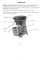
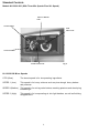
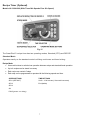
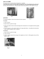
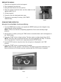
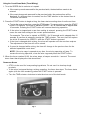
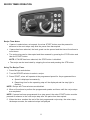
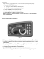
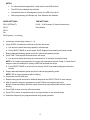
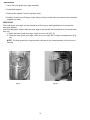
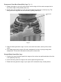
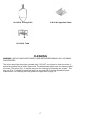
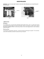
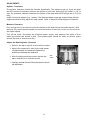
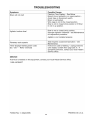
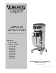
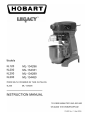
TABLE OF CONTENTS
GENERAL ............................................................................................... 3
INSTALLATION............................................................................................... 3
Unpacking .............................................................................................3
Location ................................................................................................3
Electrical Connections ...........................................................................4
OPERATION ........................................................................................... 5
Standard Controls .................................................................................6
Recipe Timer Control.............................................................................7
Bowl Placement.....................................................................................8
Agitator .................................................................................................8
Prepare for Mixing .................................................................................9
Standard Timer Operation .....................................................................9
Recipe Timer Operation ................................................................................11
View Recipe ..................................................................................................12
Programming Recipe Timer ..........................................................................12
Unloading ............................................................................................14
Wire Cage............................................................................................14
Agitators and Attachments ...................................................................16
CLEANING ...................................................................................................17
MAINTENANCE ............................................................................................18
Lubrication ............................................................................................18
Adjustments ..........................................................................................19
TROUBLESHOOTING ............................................................................. 20
Service..................................................................................................20
© HOBART 2006
2
Installation, Operation and Care of
LegacyTM 12 & 20-Quart Mixers
SAVE THESE INSTRUCTIONS
GENERAL
The Legacy 12-quart mixer is a bench-type mixer which features a SmartTimer™, a manual bowl
lift and a #12 attachment hub as standard equipment.
The Legacy 20-quart mixer is a bench-type mixer which features a SmartTimer™, a manual bowl
lift and a #12 attachment hub as standard equipment. With the use of special agitators, a 12
quart bowl may be used on the HL200 mixer.
A variety of attachments, agitators and accessories are available. These are described in a
separate Use and Applications Handbook, which is furnished on the Legacy Mixer Operator
Training CD provided with each mixer.
INSTALLATION
UNPACKING
Immediately after unpacking the mixer, check for possible shipping damage. If this machine is
found to be damaged after unpacking, save the packaging material and contact the carrier within
15 days of delivery.
LOCATION
Prior to installation, test the electrical service to assure that it agrees with the specifications
on the machine data plate.
Place the mixer on a suitable sturdy level surface. There should be adequate space around the
mixer for the user to operate the controls and to install and remove bowls.
Holes are located in the base to permanently secure the mixer, although this is not necessary
in normal installations.
3
ELECTRICAL CONNECTIONS (Cord Connected Mixers)
WARNING: THE ELECTRICAL CORD ON THIS MACHINE IS EQUIPPED WITH A THREEPRONGED GROUNDING PLUG WHICH MUST BE CONNECTED TO A PROPERLY GROUNDED
RECEPTACLE. IF THE RECEPTACLE IS NOT THE PROPER GROUNDING TYPE, CONTACT AN
ELECTRICIAN. DO NOT REMOVE THE GROUNDING PRONG FROM THE PLUG.
WARNING: ELECTRICAL AND GROUNDING CONNECTIONS MUST COMPLY WITH THE
APPLICABLE PORTION OF THE NATIONAL ELECTRICAL CODE AND/OR OTHER LOCAL
ELECTRICAL CODES.
Check Initial Operation
1. Apply power to the mixer by inserting the cord plug into a properly grounded outlet.
2. Install the bowl and raise into mix position, with the bowl support up and bowl guard wire
cage closed.
3. Turn the SPEED dial pointer to STIR.
4. Momentarily run the machine by pushing the START and then STOP buttons.
4
OPERATION
WARNING: MOVING AGITATOR IN BOWL. KEEP HANDS, CLOTHING, AND UTENSILS OUT
OF BOWL WHILE IN OPERATION. DO NOT USE WITHOUT INTERLOCKED GUARD.
The Legacy mixer is equipped with SmartTimerTM controls. Refer to Fig. 1 for operating parts and
OPERATION section for their functions.
The bowl guard wire cage must be in closed position or the mixer will not operate.
The bowl must remain in mix position on bowl support and the bowl support must be raised (mix
position) or the mixer will not operate.
SLOT
CONTROLS
ATTACHMENT
HUB
SPLASH GUARD
DRIP CUP
APRON
BOWL GUARD
WIRE CAGE
BOWL SUPPORT
AGITATOR
Fig. 1
5
Standard Controls
Models HL120/HL200 (With Three Mix Speeds Plus Stir Speed)
DISPLAY MIXING
TIME
STOPS MIXER
TIME
SELECTOR
STARTS MIXER
SPEED SELECTOR
Fig. 2
HL120/HL200 Mixer Speeds
STIR (Slow)
The lowest speed is for incorporating ingredients.
SPEED 1 (Low)
This speed is for heavy mixtures such as pizza dough, heavy batters
and potatoes.
SPEED 2 (Medium)
This speed is for mixing cake batters, mashing potatoes and developing
bread dough.
SPEED 3 (High)
This speed is for incorporating air into light batches, as well as finishing
whipped items
6
Recipe Timer (Optional)
Models HL120/HL200 (With Three Mix Speeds Plus Stir Speed)
Fig. 15
The SmartPlus2 ™ recipe timer has two operating modes, Standard (STD) and RECIPE.
Standard Mode
Operates exactly as the standard controls utilizing continuous and timed mixing.
Recipe Mode
x
Use mode buttons to switch mixer operation between recipe and standard timed operation.
x
Up to 4 recipes can be stored in memory
x
Each recipe can contain 5 steps
x
Each step can be programmed to operate with the following speeds and time.
SPEED SETTINGS
TIME SETTINGS
SPd 1 (DEFAULT)
00:00 – 15:00 minutes (10 second increments)
SPd 2
End (default)
SPd 3
Stir
PAUS (pause – no mixing)
7
BOWL PLACEMENT
The bowl must be installed before the agitator is installed.
To install the bowl, lower the bowl support and position bowl so the alignment pins on the left
side of the bowl support fit in the holes in the bowl tab. (Fig. 3) Place the slotted tab on bowl
into the lower part of the pin. Swing the bowl into the mix position on bowl support. (Fig. 4)
Fig. 3
AGITATOR
To install an agitator, the bowl must be on the bowl support.
Fig. 4
To Install
1. Lower the bowl.
2. Open the bowl guard wire cage.
3. Place the agitator inside the bowl and align the horizontal slot on the agitator with the agitator
shaft pin.
4. Slide the agitator up the agitator shaft until it stops and latches. An audible click should be
heard when the agitator locks in position.
To Remove
1. Open the bowl guard wire cage.
2. Lower the bowl.
3. Hold the agitator and pull the plunger of the agitator out (Fig. 5). Slide agitator down off the
agitator shaft.
Fig. 5
8
PREPARE FOR MIXING
1. Place the mixing bowl on the bowl support.
2. Pour ingredients into the bowl.
3. Swing the bowl back to the mix position.
4. Place the agitator inside the bowl, and then attach it to the
agitator shaft (Fig. 6).
5. Lift bowl support.
6. Correctly close the bowl guard wire cage.
7. The mixer is now ready for mixing. (See TIMER
OPERATION.)
Fig. 6
STANDARD TIMER OPERATION
Using the Count-Up Mode (Continuous Mixing)
1. Turn the SPEED dial to select a mix speed (the SPEED setting can be changed at any
time during the mixing operation).
NOTE: STIR is to be used for incorporating ingredients. Do not use to develop dough
products.
2. Set the timer on hold by turning the TIME selector counterclockwise until HoLd appears in
the TIME window.
3. Press the START button to begin mixing. The timer starts counting forward from 00:00.
NOTE: If the wire cage is opened at any time, the mixing operation will stop. To resume
the mixing operation, close the wire cage and press the START button.
4. Use the STOP button to stop the mixer; the mixing time is displayed in the TIME
window.
5. Press the START button to resume mixing if needed.
NOTE: When the timer reaches 15:00 minutes, the beeper will sound momentarily and
timer will rollover to 00:01 and continue counting until the STOP button is pressed.
Fig. 7
9
Using the Count-Down Mode (Timed Mixing)
1. Turn the SPEED dial to select a mix speed.
a. If the count-up mode was used for the previous batch, the desired time needs to be
entered.
b. If the count-down mode was used for the previous batch, the previous time will be
displayed. If a different time is needed, turn the TIME selector to the desired time in
10 second increments.
2. Press the START button to begin mixing; the timer starts counting down from the set time.
a. To stop the mixer at any time, press the STOP button. To resume mixing, press the START
button. For example: The mixer is started at SPEED 1 for 30 seconds and is stopped after
10 seconds. Pressing the START button will resume the mixing operation.
b. If the mixer is stopped and a new time setting is entered, pressing the START button
saves the new time setting on the current speed selection.
For example: The mixer is started at SPEED 1 for 30 seconds and is stopped after 10
seconds. A new time is entered by turning the TIME selector. The new time will replace
the initial 30 seconds for SPEED 1 after the START button is pressed.
c. If the time is changed while mixing, the mixer will operate until the new time expires.
The adjustment to the time will not be stored.
d. If speed is changed while mixing, the time will change to the previous time for the
selected speed and count down.
NOTE: If the wire cage is opened at any time, the mixing operation will stop. To
resume the mixing operation, close the wire cage and press the START button.
3. When the timer reaches 00:00, the mixer stops; a beeper sounds for 1 second. The countdown timer then displays the last-stored time.
OPERATING NOTES
x STIR is to be used for incorporating ingredients. Do not use it to develop dough
products.
x If the mixer is stopped during a mixing operation, the timer also stops. The timer starts
again (with the time remaining) when the START button is pressed.
x Turn the TIME selector clockwise to take the mixer out of the hold mode.
Fig. 8
10
RECIPE TIMER OPERATION
Recipe Timer Notes
x If pause is selected as a mix speed, the mixer START button must be pressed to
advance to the next recipe step after the pause time has expired.
x If pause has been selected, the bowl guard can be opened and the time will continue to
count down.
x The recipe step can be interrupted and then resumed by pressing the STOP button and
then the START button.
NOTE: If PAUSE has been selected, the STOP button is disabled.
x The recipe can be terminated by stopping the mixer and pressing the STD button.
Using The Recipe Timer
1. Press Recipe mode button.
2. Turn the RECIPE selector to select a recipe.
3. Press START; mixer will operate at the programmed speed for the programmed time.
a. Speed is displayed momentarily.
b. Remaining time for the operating step will be displayed and the step light is
flashing.
NOTE: Recipe and Time selectors are disabled.
4. Mixer will continue to perform the programmed speeds and times until the recipe steps
are completed.
NOTE: If pause has been programmed for a step speed, the mixer START button must be
pressed to advance to the next recipe step after the pause time has expired.
5. When the timer reaches the end of the last programmed recipe step, the mixer stops;
the beeper sounds; the selected recipe is displayed.
11
View Recipe
When the mixer is in RECIPE mode, you can view the step settings of any recipe.
1. Press the SELECT/SAVE button.
A. Display will alternate between speed and time.
B. The LED of the step being displayed will flash.
2. Use the arrow buttons to view the next step.
3. Use the Recipe selector to view other recipes.
4. Press PGM button to return to the RECIPE mode.
NOTE: If the mixer is performing a recipe, the recipe will continue to operate in normal
recipe mode sequence.
PROGRAMMING RECIPE TIMER
Fig. 16
HL200 is powered with display showing a mix time (Standard Mode) or recipe number (Recipe Mode).
1. If a mix time is displayed, Press RECIPE mode button. Display corresponds with position of recipe
(speed) selector.
2. Press and hold TIME. Continue holding TIME, then press PGM and hold until rP1 is displayed (with
step 1 blinking), buzzer sounds and programmed step LEDs are lit.
3. Use arrows to select recipe number (1-4) for programming.
4. Press SELECT/SAVE to enter program mode for the recipe number selected.
Buzzer sounds and display alternates between speed and time to indicate programming mode.
12
NOTES:
x
If a value has been assigned for a step number, that LED will be lit.
x
The LED for the selected step will blink.
x
If the default value is still assigned to a step, the LED will not be lit.
x
When programming, the Recipe and Time Selectors are disabled.
SPEED SETTINGS
TIME SETTINGS
SPd 1 (DEFAULT)
00:00 – 15:00 minutes (10 second increments)
SPd 2
End (default)
SPd 3
Stir
PAUS (pause – no mixing)
5. Use arrows to select step number (1 – 5).
6. Press SPEED. All characters will blink and buzzer will sound.
A. Use arrows to select the mixing speed for selected step.
B. Press SELECT/SAVE to set the speed. SAVE displayed momentarily and buzzer sounds.
7. Display alternates between speed and time to indicate programming mode.
8. Press TIME. Third digit will blink and buzzer will sound.
A. Use arrows to select the mixing time (increments of 10 seconds) for selected step.
NOTE: If all 5 steps are programmed, the recipe will terminate at the end of step 5. If fewer than 5
steps are used, the default time setting of END will terminate the recipe.
B. Press SELECT/SAVE to set the time for the step. SAVE momentarily displayed and buzzer
sounds.
9. Display alternates between speed and time to indicate programming mode.
NOTE: LED of step programmed will be flashing.
10. Use arrows to select next step.
11. Repeat setting speed and time for additional steps and use SELECT/SAVE to save settings.
12. After all steps for recipe are programmed, press PGM to exit programming mode.
Buzzer sounds and display will show recipe number that was programmed with the number
blinking.
13. Press PGM to enter run mode. (Buzzer sounds)
14. Press STD to return to standard mode or set recipe selector to the desired recipe.
15. Select the recipe that you programmed and verify proper operation.
13
UNLOADING
1. Open the bowl guard wire cage assembly.
2. Lower bowl support.
3. Remove the agitator from the agitator shaft.
4. Slightly lift the bowl off the pin (right side), pull bowl to the front and remove from the bowl
support (left side).
WIRE CAGE
The bowl guard wire cage can be rotated out of the way to add ingredients or to access the
bowl and agitator.
Note how the plastic carriers allow the wire cage to ride around the circumference of the planetary
drip cup.
x Open the bowl guard wire cage: rotate it to your left (Fig. 9).
x Close the bowl guard wire cage: rotate it to your right until it stops, closed position (Fig.
10).
NOTE: The bowl guard wire cage must be returned to the closed position for the mixer to
operate.
Fig. 9
Fig. 10
14
Remove and Clean Bowl Guard Wire Cage (Fig. 11)
1. Rotate wire cage to your left until the three carriers align with the carrier escape slots in
the circular ridge of the planetary drip cup.
2. Lift the wire cage straight up so the carriers escape from the slots on the drip cup. The
bowl guard wire cage can now be removed by pulling toward you.
Escape Slots
(3)
Fig. 11
3. Wash the bowl guard wire cage in a sink, rinse with clear water, and dry with a clean
cloth.
4. The splash guard can be wiped off and/or washed with a cloth or sponge using warm,
soapy water. Rinse with clear water and dry with a clean cloth.
Reinstall Bowl Guard Wire Cage
1. Position the ring of the bowl guard wire cage so the carriers are positioned above the slots
in the planetary drip cup.
2. Lower the bowl guard wire cage so the carriers pass through the slots.
3. Rotate the bowl guard wire cage to your right until it contacts the stop, closed position.
15
AGITATORS AND ATTACHMENTS
Attachments for attachment hub and agitators are covered in a separate Hobart Legacy Mixer Use
and Application Handbook on the Mixer Operator Information CD. Follow the instructions
accordingly.
Available Agitators and Attachments
12 & 20 Qt. B Flat Beater
12 & 20 Qt. D Wire Whip
12 & 20 Qt. ED Dough Hook
20 Qt. E Dough Hook
12 & 20 Qt. SST Bowl
12 & 20 Qt. Scraper
12 & 20 Qt. Splash Cover
12 & 20 Qt. C Wing Whip
16
12 & 20 Qt. P Pasty Knife
12 & 20 Qt. Ingredient Chute
12 & 20 Qt. Table
CLEANING
WARNING: UNPLUG MACHINE POWER CORD BEFORE BEGINNING ANY CLEANING
PROCEDURES.
The mixer should be thoroughly cleaned daily. DO NOT use a hose to clean the mixer; it
should be washed with a clean, damp cloth. The base allows ample room for cleaning under
the mixer. The apron (Fig. 1) may be removed for cleaning by loosening the screws. The
drip cup (Fig. 1) should be removed (which is secured with 3 screws) periodically and
wiped clean. For cleaning the bowl guard wire cage refer to page 15.
17
MAINTENANCE
WARNING: UNPLUG MACHINE POWER CORD BEFORE BEGINNING ANY MAINTENANCE
PROCEDURES.
Slideway
Planetary
Seal
Fig. 12
Fig. 13
LUBRICATION
Slideways
The slideways (Fig. 12) should be lubricated approximately twice a year. To reach these areas,
fully lower the bowl support and remove the apron, which is secured by slotted screws. Wipe a
thin coat of Lubriplate 630AA on the bowl pad area of the bowl supports and on each slideway.
Install the apron.
Planetary Seal
Occasionally, the planetary seal (Fig. 13) may become dry and begin to squeak. To correct this,
work a little lubrication (mineral oil) under the lip of the seal.
18
ADJUSTMENTS
Agitator Clearance
The agitator clearance should be checked periodically. The agitator must not touch the bowl
and the maximum clearance between the bottom of the bowl and the B flat beater is 1/8" (3
mm); the maximum clearance between the bottom of the bowl and the ED dough arm is 5/16” (8
mm).
Install a bowl and agitator (e.g., beater). If the bowl and beater come into contact before the bowl
support reaches its stop, adjust the stop screws. Refer to Adjust the Bowl/Agitator Clearance.
Measure Clearance
Pour enough flour in the bowl to cover the bottom of the bowl where the beater travels. With
the bowl fully raised (beater should not touch the bottom of the bowl), briefly run the mixer at
the lowest speed.
Turn off the mixer, disconnect the electrical power supply, and measure the depth of flour
where the beater has traced a path. This measurement should be taken at several points
around the bowl to assure accuracy.
Adjust the Bowl/Agitator Clearance
x Remove the apron (which is secured by screws).
x Adjust the clearance by moving the stop screws
counterclockwise to increase the clearance or
clockwise to decrease the clearance.
x After the adjustments are made, replace the
apron and secure it with the screws.
x Carefully operate the bowl lift several times to check
the adjustment.
19
Stop
Screw
Fig. 14
20