1
~
"$'' "; ~~
"
,
~',
~"A
@"ii9\'I:,l~
"I:\;;;i\\'",
~:.-
~
@
"
@
"
e>.
@'
,',
@'~;i,
~:.iA
~
'
l'
I:
~:
.
,\1:\:,A
~
@
' ~:~-
~
~",'a
@~,
~.~':I.._~
@~
~
~:~-
~
"
@ ~
,'
;
,\ l,
.'
~~::-
1f
.
'i*'
.,'
'
1A
"
z
.'...
~
~
~~:.-~A"~~
"
~.:rt:::-~
,.~:-
~:.-
~
,
...~:-
04.~=- ~.~:-
~
~~
,"
"
I'
~
.
, $
~:.1W
(!:""$
!IIfI
z'
~
~
@
,\~'
~.~/
,;I:\;;~A\,,'a
~
i
\\'
~::_.'
i
~:~... ~~:.- ~~:-
~
\
...~=-~~~:~,
.0
,~¥
."
,::",,;
~~~-
~
3Z
,
@,::",\,I:,'"
"3,.0", ,z' ,
1:'" ,_.0
1
TABLE OF CONTENTS
Page
Parts Layout. . . . . . . . . . . . . . . . . . . . . . . . . . . . . . . . . . . . . . . . . . . . . . . . . . . . . . . . . . . . . . . . . . . . . . . . . . . . . . . 2
Knots to Use
2
FramingtheHulls
4
Trampoline. . . . . . . . . . . . . . . . . . . . . . . . . . . . . . . . . . . . . . . . . . . . . . . . . . . . . . . . . . . . . . . . . . . . . . . . . . . . . . . . 5
Rudder&TilierSystem
:
7
Mast & Rigging. . . . . . . . . . . . . . . . . . . . . . . . . . . . . . . . . . . . . . . . . . . . . . . . . . . . . . . . . . . . . . . . . . . . . . . . . . . . . 8
Stepping the Mast
10
TrapezeWires
13
Mainsail. . . . . . . . . . . . . . . . . . . . . . . . . . . . . . . . . . . . . . . . . . . . . . . . . . . . . . . . . . . . . . . . . . : . . . . . . . . . . . . . . 1 4
MainsheetSystem
16
Jib Sail. . . . . . . . . . . . . . . . . . . . . . . . . . . . . . . . . . . . . . . . . . . . . . . . . . . . . . . . . . . . . . . . . . . . . . . . . . . . . . . . . . 1 8
Righting. . . . . . . . . . . . . . . . . . . . . . . . . . . . . . . . . . . . . . . . . . . . . . . . . . . . . . . . . . . . . . . . . . . . . . . . . . . . . . . . . 20
Trapeze Use. . . . . . . . . . . . . . . . . . . . . . . . . . . . . . . . . . . . . . . . . . . . . . . . . . . . . . . . . . . . . . . . . . . . . . . . . . . . . 22
Reefing
24
Safety
26
Parts List
27
Maintenance Mooring, Trailering
30
IMPORTANT NOTICE. This manual is devoted to increasing your safety and enjoyment of your Hobie Cat.
We ask that you read it all thoroughly and TRY OUR WAY FIRST! Please pay particular attention to the
Safety section and the Maintenance, Mooring, and Trailering sections. It would also be a good practice to
review these on a periodic basis.
DANGER!!
Watch for overhead wires whenever you are sailing,
launching, or trailering with the mast up. The mast sticks up there a long
way and shock or death could result if it comes in contact with overhead
wires. So look up when moving the boat around or even stepping the
mast and give any wires a wide berth.
Patent Numbers 24606.3575124,3921561.3929066,352753,691922, 905789, 3678876
Copyright @ December 1980 Coast CatamaranCorp.
Photography by J. Halcrow
1
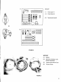
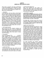
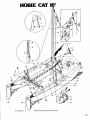
PARTS LAYOUT
MAJOR COMPONENTS
6
;,
FIGURE
1.
Port Hull
2.
Starboard Hull
3.
Rudder Assemblies
4.
Aft Crossbar
5.
Forward Crossbar
6.
Boom
7.
Sidebars
8.
Tiller Extension and
Crossbar Assembly
9.
Battens: Main & Jib
1 O.
Rig Kit
11.
Sail Bag
12.
Mainsail
13.
Jib
14.
Trampoline
15.
Mast (not shown)
1
KNOTS TO USE
~..~q"
FIGURE 8 KNOT
2
BOWLINE KNOT
.\\.
I
17.
RIG KIT
-
CrJ1~~~~~~~ 18.
17.
:::::~::::=::::5
~
~
~
~
.
-@UU
@
PartsCard # 1
Parts Card #2
@
~~
@
20.
MainsheetSystem
-@oa
-@
~~g,O~
20.
18 .
tt~~~~~
><=
><=
><=
10
01
10
01
FIGURE 2
WIRE SET
I'
f
23.
"
,
24.
Jr'" ~\;;;."."
J;
;;;;
.";
I
'~c
1~;;:
; :;x
\~fuc:,
c.
Halyard Assembly
;
,c,
cfuci"cc
fu~
x
c;c,,"
Bridles
Shrouds, Forestay, & Jib
'\?cl:i~
':
25.
Trapeze Wire Shock Cord
26.
Trapeze Wires
, ;;.c~;,c:c:4:
,," "3~~~~
~~~
;c~J'
",;
FIGURE 3
3
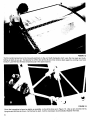
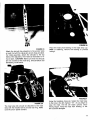
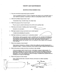
FRAMING THE HULLS
Tools needed:Rubber mallet, adjustable crescent wrench, screwdriver, and pliers.
FIGURE 4
FIGURE 5
Assemble the frame components as shown in the
photo. The flared portion of the sidebar track must be
forward and facing inward.
With an assistant, position the hulls as shown, using
the packing carton end caps for assembly stands.
Make sure that the flatter sides of the hulls face outward. Carefully place the frame on the pylons, aligning it so that each corner casting in turn can be started
onto its pylon. Do not drive the castings down until all
have been equally started.
.co""
"
.co--
.co,
"
~
FIGURE 6
FIGURE 7
Beginning at the left front, drive each corner casting
down onto the pylon until the bolt holes line up.
NOTE: Strike the casting directly over the pylon only.
Binding or damage could otherwise result. Use a soft
mallet only.
Once all the castings are properly positioned, install
the pylon bolts and nuts, with the nuts inboard. Tighten
securely, but do not over-torque.
4
TRAMPOLINE
FIGURE8
FIGURE9
Insert trampoline half into the flared sidebar track so
that the grommets are running down the center and
across the back. The hiking straps should be on top.
Position the forward edge even with the forward
crossbar.
Insert the forward edge of the trampoline into the front
crossbar track adjacent to the corner casting and
slide it all the way to the center. Repeat steps 8 and
9 for the opposite side.
I
FIGURE 10
FIGURE 11
Install the aft lacing strip by feeding the larger bead
into the track in the aft crossbar. Make sure it is
Tie each aft lacing line to the aft corner casting as
shown.
-
centered.
5
~~
./~
.
c
,
~:C",~;i!;";i!;;~~;i!;CC",
,~-~~,...,.'
.
FIGURE 12
Tie the center lacing line to the forward grommet on the port (left) trampoline half. Lace the line back and forth,
taking up slack as you go. Temporarily tie off the line at the aft end, then remove slack again by working it out front
to back. Lace the two aft lines simultaneously in the same manner.
"'"'
J.
FIGURE 13
Once the trampoline is laced as tightly as possible, re-tie all the lines as in Figure 13. Use up any excess line by
tying several hitches as shown. As the boat is used, it will be necessary to periodically retighten the lines.
6
RUDDER & TILLER SYSTEM
.
i
r
.,
~@
ii";,,,,"
,,~
"~~
FIGURE14
Installthe left rudder assemblyonto the transomof
the left hull. The nylon nuts will be facing inboard.
With the tiller arm held out of the way, slip the rudder
pin - cotter key up - down throughthe castingand
gudgeons.Once in place, installthe other cotter key
into the rudder pin below the casting (see Fig. 15).
Repeatwith right rudder.
FIGURE15
Install the drain plugs into their housings in each
transom.Makesure that the a-ring gasketsare properly in place.
U
~~
~
@
~
@
FIGURE 16
FIGURE 17
The illustration shows an exploded view of the tiller
connector kit. Notice that it depicts the port (left)
side. Install the tiller crossbar with the "PORT" sticker
to the left side of the boat.
Tighten the nuts until the bolts protrude about two
thread widths beyond the nylon locking elements of
the nuts.
7
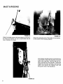
MAST & RIGGING
,
Attach the bridle wires to the bow tangs by removing
the bolts and slipping one end of each bridle into its
tang. Retighten the bolts.
FIGURE 19
Attach the opposite ends of the bridles to the shackle
on the bottom of the forestay adjuster.
The forestay and shrouds are connected by a
large shackle. Attach this shackle to the lower
hole in the mast tang, insuring that the forestay is between the two shrouds. Tighten the
shackle pin securely with pliers, then twist the
safety wire around the shackle body and
through the hole in the shackle pin.
!,
',\
~
\ \'
FIGURE 20
8
Using the shackle provided, attach the trapeze
wires to the two upper holes in the mast tang
as shown. Use the trapeze wire shock cord
to tie the lower end of the wires to the mast
during stepping. For sailing in areas of frequent
strong winds, double trapeze rigs are available
tram Hobie Ca~ dealers
FIGURE 21
!
I
To keep the jib halyard out of the way while
stepping the mast, secure it at the cleat as
shown.
FIGURE 22
9
STEPPING THE MAST
""'11
Y,
\
".,"
~
L_~~~::~J
DANGER!!
POWER LINES
Do not attempt to step the mast in an area
of overhead wires. A mast contacting an
electrical wire could be fatal.
Lay the mast on top of the frame with the
mast head aft. Notes: (a) With experience,
the mast can be stepped by one person,
but Hobie Cat recommends that you have
someone assist you; (b) Position the boat
facing into the wind, and on level ground.
If the trailer is not attached to a vehicle,
chock the wheels and have someone stand
on the trailer tongue. DANGER: Do not
raise the mast if overhead power lines are
present.
THE HOBIE(!) CATS SHOWN IN THIS MANUAL MAY BE FITTED WITH OPTIONAL OR ACCESSORY EQUIPMENT.
10
I
I
'.
FIGURE
Attach
the
shr.oud
stay
a.dju~ters
FIGURE 24
to th~ anchor
bolts
Piace
the
~~~~ i~~
25
m~st. pivot bearing
in the mast step cup.
trallerlng,
remove
the bearing
to prevent
on each hull with the clevIs pins & lock rings provided.
For initial assembly,
attach
the shrouds
to the top
holes of the adjusters,
then reset as necessary
to remove slack.
CAUTION:
are not crossed
at the
dismasting
could
Make sure that the shrouds
mast tang. Shroud
failure and
result.
FIGURE
FIGURE
The
step
mast
with
sure
the
26
step link should
be attached
to the mast
the headed
clevis pin and lock ring. Make
arrow
points
upward.
27
Using the headless
clevis pin, fasten
the mast base
to the hole in the link marked
"16".
As you begin to
raise the mast,
the
~aving
begun,
keep
link could
link will rotate
the mast from
upward.
twisting,
Once
or the
be damaged.
11
CHECK FOR WIRES
OVERHEAD. . .
. . . Check above at this time for overhead wires. Don't raise the mast if
there are any wires.
.
Stand on the rear crossbar and raise
the mast to your shoulder. At this point,
insure that the shrouds are clear of
the rudders and rear corner castings.
An assistant is recommended.
FIGURE 28
{
,'.\
\
l
-1-
FIGURE 29
Walk forward, raising the mast as you go. At the full upright position, lean the mast forward against the shrouds and
have an assistant attach the forestay. Later adjustment may be necessary.
12
Once the forestay is connected,
must be disengaged.
the mast step link
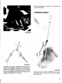
TRAPEZE WIRES
,
FIGURE 30
FIGURE 31
Assemble the trapeze adjustment components as
shown in the illustration. The shock cord should pass
beneath the trampoline frame from the port trapeze
line to the starboard line. Note: Insure that these
items are assembled exactly as above. Refer to knot
diagram, "Bowline Knot," on page 2.
FIGURE 32
Trapeze assembly installed. CAUTION: Never allow
the trapeze wires to carry any mast loads intended
for the shrouds.
13
MAINSAIL
FIGURE 33
Feed
ol:>ening
the
foot
(base)
in the
forward
of
end
the
mainsail
of the
into
the
track
boom.
FIGURE 34
Attach
the
mainsail
tack
to the
gooseneck
shackle
as
shown.
"
FIGURE 35
FIGURE 36
Tie the outhaul to the mainsail clew with a bowline
knot. Lead it around the boom cal:>,through the block
hangers, and through the outhaul jam cleat. Tie a
figure eight knot in the end of the line.
Insert each batten into its resl:>ective I:>ocket, making
sure it seats all the way into the batten I:>ocket end
I:>rotectors.
14
DIAGRAM
-
TYING DE:TAIL
CLE:AT OF"F" AT MOUT1-i OF" LE:ACH TIP
START HE:RE: WITH A
BDI.iLINE: KNOT
FIGURE 37
Photo illustrates recommended way to thread the
batten ties. Batten tension can be varied to suit personal preference or sailing conditions.
Q
Point the boat directly into the wind. Attach the halyard
shackle to the head of the sail and feed the luff (leading
edge) into the opening in the mast track. Continue
pulling the halyard and feeding the sail into the track
until it reaches the top.
FIGURE 38
<;J
When the sail is all the way up, pull the halyard forward
sufficient for the stop sleeve to clear the halyard hook.
FIGURE 39
Once the sleeve is past the hook, position the halyard
so that the sleeve will engage the hook when you
release tension. That done, route the halyard from
the front to the starboard side, and around behind the
starboard shroud and trapeze wires. Secure it to the
mast cleat and stow the excess line (see Figure 41).
FIGURE 40
15
MAIN
SHEET SYSTEM
FIGURE 42
1
Attach the ratchet block to the traveler car
FIGURE 41
Insert the gooseneck into the mast track. Tie the
down haul line onto the ring and lead it through the
cleat and ring as shown to provide multi-purchase
leverage. Apply desired downhaul tension and cleat
the line. Notes: (a) Do not re-insert the sail into the
mast track below the track opening; (b) On a new
boat, it is sometimes easier to adjust downhaul with
the mainsheet system installed and sheeted in. Keep
an eye on the wind.
Q
~~~~-
c~
FIGURE 43
Shackle the boom blocks to the block hanger
boom.
on the
FIGURE 44
Install mainsheet line as shown.
16
.-
~
~
...
""a"
'"~J¥a
~-~~
~J¥
'"
'"
-
I
\
\
\
"~
FIGURE 46
Mainsheet tension is held by pulling the mainsheet
at an upward angle, which sets the line between the
camjaws.
~
FIGURE 45
Run the free end of the mainsheetthroughthe cam
cleat
the travelercar, and the dead
eye behind the cam cleat. Tie a figure eight knot to
secure the line.
FIGURE 47
A quick, downwardsnap on the line will free it from
the cam cleat, releasingtension.The travelercontrol
works identically, but in the opposite direction.
Before sailing, practice this until you are proficient.
17
JIB SAIL
FIGURE49
c
"
Attach the jib tack to the shackle on the forestay
adjuster.
~
FIGURE 48
Install the jib battens (refer to Figure 36 & 37). Attach
the jib halyard to the head of the jib and secure the
plastic hank to the forestay by twisting it 90 degrees
onto the wire. Raise the jib about 3/4 of the way and
temporarily cleat the line.
Thread the jib halyard around the cheek block at the
base of the mast, through the jib down haul block,
and around the cleat as shown. Raise the jib the remaining distance, then tension the line until there is
about 4" to 6" of slack in the forestay. Secure the
line to the cleat and stow the excess.
(]
FIGURE 51
FIGURE 50
18
Shackle the jib clew blocks to the center hole of the
jib clew plates. CAUTION: In windy conditions, do
not allow the jib to flap at this step. The clew plate
and attached blocks could cause an injury.
FIGURE 53
Lead the free end of the jib sheet to the opposite jib
sheet block. Route it identically to the first side, but in
reverse order. The cam cleats operate the same as
those in the mainsheet system.
FIGURE 52
Tie one end of the jib sheet around the clevis pin in
one of the jib sheet blocks. Lead it to the clew block
and back through the cam cleat as shown.
Re-check all shackles and clevis pin lock rings. (Please
take this opportunity to read the safety section before
sailing.)
E
~
.c
0>
c
"2
c
::J
()
...
Q)
.c
00
"'ii)
'c
.c
()
"0
'0
.c
0..
FIGURE 54
Your Hobie@ 1 6 is ready to sail.
19
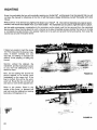
RIGHTING
Since
it
not
is
predictable
have
this
that
manual
you
for
will
eventually
reference
at
capsize
the
time
(it
your
will
Hobie
float
Ca~
away),
and
please
because
it
familiarize
can
be
yourself
assured
that
thoroughly
you
with
will
what
follows:
Always
carry
mended,
but
this
It
system.
takes
16.
Stow
people
to
hang
so
full
holding
aboard
in
dolphin
striker.
right
the
boat
it
a
Hobie
<!>
The
procedure
as
manner
as
method
is
to
to
the
allow
tie
16.
mainsheet
One
half
can
sheet
must
immediate
each
end
inch
be
used
first
be
access
around
diameter
to
forward
rope
the
removed
whether
the
poly
right
from
the
pylons,
is
boat
boat
in
the
recoma
won't
of
Next,
mainsheet
is
then
on
its
side
wrap
the
cap-
be
falling
into
the
the
be:
the
righting
plate)
hull.
on
Route
(or
to
of
hold
about
to
line
at
turtled,
down
Refer
the
traveler
attempting
adjuster
is
jibsheet,
mainsheet
lift
a
water.
tie
center
the
upper
will
the
photos.
the
lower,
the
45
the
If
the
over
Stand
line,
or
55
the
that
hull
one.
in
leeward
righting
FIGURE
wind-
opposite
or
degrees
the
point
hull.
be
line
to
the
around
anchor
this
over)
onto
its
.~
the
hull
leaning
so.
c
'
FIGURE
20
pinch,
over
shouldn't
or
such
popular
the
your
dealer.
Hobie
as
turn
on
aboard
Hobie
to
One
jumping
and
shroud
back
line
the
uncleat
you
and
line
your
sail.
sail
and
righting
from
(turtled).
normally
Avoid
so
ward
onto
doesn't
mainsheet,
boat
the
two
fast,
long
complication
the
Second,
(chain
available
around
difficult.
the
foot
be
loop
It
very
20
inverted
First,
sizes.
to
unnecessary
completely
excess
15
should
adds
block
or
a
and
56
Helpful
the
hint:
wind
can
to
to
FIGURE
Try
so
be
it
to
will
get
help
accomplished
one
end
or
by
the
"weathervane"
head
that
freed
in
is
like
the
stuck
mast
you
right
shifting
other
and
the
boat
in
a
pointed
the
into
boat.
your
allowing
around.
muddy
bottom
This
weight
the
wind
A
mastcan
be
fashion.
57
f(
k~::
.
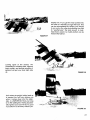
Looking
again
combinati~n
at
of
a
~~~~n~~g~~,
the
photos,
helping
the
wind,
As
it
prevent
returns
when
fully
if
you
to
upright,
the
it
it
to
1£
~
',.
"cyA.a
",:"c~j
~
g~~dy~~~e~~la~~~oh~d~do~
to
on
;
8'
;~~c~~
vigorous
up.
Also,
O
hull
comes
is
the
down
righting
line.
to
will
away
58
FIGURE
59
up
you
water.
you
Having
boat
sail
hand
the
that
your
it
a
striking
into
IMPORTANT
righted
allow
hold
from
FIGURE
hang
successdo
without
no
good
you.
21
-
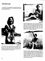
TRAPEZE USE
The Hobie@ 16 is equipped with a trapeze system for
maximum speed and fun. You should become familiar
with it prior to its use.
~~
FIGURE 61
Adjust the trapeze line by moving the rope lock up or
down to compensate for your height and the desired
"hiking out" angle. The adjustment should not be such
that the user is easily dragged through the water
when sailing through waves, chop, etc. Sit on the
sidebar as shown and connect the lower end of the
dog bone to your trapeze seat hook.
FIGURE 60
The trapeze seat components are assembled as
shown, the hook always pointing downward. After
the trap seat has been put on, run the lace lines
through the grommet on the shoulder strap and tie
the lines together in a figure 8 knot.
FG
E
I UR 62
Lean back, holding onto the plastic trapeze handle for
balance, and ease yourself out by pushing away with
your legs. Make sure that your weight is supported
by the trap seat rather than by your "hanging" on the
handle. Otherwise, the hook could become disengaged. DO NOT hook up and fall backwards out
over the side. This could cause overstressing and
failure of the trapeze line.
22
i
I
I
!
I,
i
FIGURE 63
Maintain control of the tiller and sheets as you extend out into the trapeze position. Keep your feet
about shoulder width apart and your knees slightly bent.
Trapeze system in use (Double Trapeze rig and
Deluxe Trapeze Seats are extra-cost accessories). While using the trapeze, watch the opposite
hull. Adjust for proper trim by shifting weight
fore and aft; do not allow the leeward bow to
submerge, or the boat may decelerate or stop
abruptly, causing the occupants to be thrown
forward still attached to the trapeze wire.
FIGURE 64
23
SAFETY
IMPORTANT:
READ BEFORE SAILING'
While sailing is generally a safe sport, carelessness
or lack of knowledge can be dangerous. A little
common sense and attention to a few precautions
go a long way toward protecting your safety in anything you do, including sailing.
1.LIFEVESTS
In the first place, don't sail without a Coast Guard
approved life vest or jacket for each person on board.
A Type 1 PFD is an approved device designed to
turn an unconscious person in the water from a face
downward position to a vertical or slightly backward
position, and to have more than 20 pounds of
buoyancy, recommended for off-shore cruising and
acceptable for all size boats. If you're sailing in any
kind of a heavy sea or strong winds, you should
have your life jacket or vest on. Accidents do happen
occasionally, even to the best of swimmers, and
when they do, they usually happen quickly. Also
remember to have an adequate paddle and righting
line on board at all times, along with one type 4
throwable flotation device.
2. OFF SHORE SAILING
Don't sail far out to sea. Weather conditions can
change rapidly and even if you're an experienced
sailor, old Mother Nature can sometimes get the best
of you. You should never sail alone where you can't
find shelter within a fairly close range or at least
summon assistance.
3. EQUIPMENT
Know your equipment! The
is built of
quality materials and requires little maintenance,
but for safety's sake, you should inspect it occasionally. Check the seals in your mast by pushing it
underwater and watching for air bubbles. If it is
leaking, have it resealed. A mast full of water makes
righting a capsized boat awfully difficult. If you find
the hulls are taking on an appreciable amount of
water, check the foam plugs in the pylons by removing the trampoline frame. If leakage continues,
check the through-hull fittings (screws) and apply
silicone rubber sealant, if necessary.
4. WEAR AND TEAR
"Check your shroud anchor pins, rudder pins, tiller
arm connections, and tiller extension swivel. They
will become worn with continued use. A little preventlve maintenance can prevent a failure on the water.
24
5. PRE-SAILING CHECK OUT
When you're stepping the mast, tighten your
shackles with pliers. These can't vibrate loose if
they're cinched down tightly. If one of these comes
loose while sailing; you risk damaging the boat or
even being hit by a falling mast.
6. ELECTRICAL DANGER
Watch for low overhead electrical wires whenever
you are sailing or trailering with the mast up. The
mast sticks up there a long way and shock or
death could result if it should come in contact with
overhead wires. So look up when moving the boat
around and give any wires a wide berth.
The Hobie Ca~
will give you so many hours of
trouble-free sailing that the tendency is to forget
to look at any of the hardware until something wears
out completely. Make it a habit to check the boat
out each time before you sail.
HOBIE CLASS ASSOCIATION
The Hobie Class Association was started by a group
of Hobie owners who got together back in 1968
to organize some racing and other activities. Hobie
was the mainstay of the group promoting the activities himself. At that time, it wasn't really a class
association but simply a group of owners wanting to
have fun with their new toys. Hobie would write brief
news letters from the factory announcing regattas as
they developed across the country. He published a
set of class rules rigidly restricting changes and
modifications which can be made to the boat. As
the class started to grow, people were hired to help
administer the program. At that point, the association
became a little more formal: the groundwork for the
establishment of fleets was developed and the Hobie
Cat.Hotiine was initiated as a class newsletter.
The Class Association was originally organized
around one basic consideration: to extend each
Hobie owner's enjoyment through organized, family
oriented activities. Innovations were made in racing
procedures and the regatta structures. A policy of
including the whole family in the activities developed
to assure everyone would have fun at a Hobie
regatta. The Association
continually strives to
develop better programs so owners may further
enjoy their Hobies.
HOBIE CAT I
37
38
Revised9/8/78
@COPYRIGHT 1978 COAST CATAMARAN
25
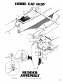
HOBIE CAT 14~16'
11
21
17
RUDDER
ASSEMBLY
Revised 9/8/78
@COPYRIGHT 1978 COAST CATAMARAN
27
HOBIE CAT 16'@
INDEX
NO.
1
2
3
4
5
6
7
8
9
10
11
12
13
14
15
16
17
18
19
20
20a
21
22
23
24
25
26
27
28
28a
29
29a
30
31
31a
32
33
34
34a
35
36
DESCRIPTION
Mast head assembly
S.S. sheave pin
Nylon sheave
Main halyard wire w/shackle
Main halyard shackle
Main halyard rope
Mast tang
Shroud shackle, 5/16", packaged
Pigtail kit, upper section, packaged
Forestay assembly, both sections
Forestay, lower section w/jib hlyd block
Jib halyard block assy.
Trapeze wires w/handles, one pair
Shroud
Jib halyard wire w/shackle
Jib downhaul block
Jib halyard rope
Jib downhaul cheek block
Mast base
Mast assembly
Mast extrusion (plugged but bare)
Adjuster ring
Adjuster pin, 1/2"
Forestayadjuster, 10 hole
Shackle, 1/4"
Bridle, wires, both sides
Jib clew block
Jib sheet line
Front crossbar assembly
Front crossbar (less castings)
Jib traveler track stops
Screw, #8 x 1" flathead
Jib traveler track
Jib sheet block w/car
Clevis pin
Jib block cam jaws (pair)
Bow tang
Screw,5/16"-18x1-1/4RHMS
Nut, 5/16" s/s
Hull/starboard (special order)
Stay adjuster
INDEX
NO.
40
41
42
42a
43
43a
43b
44
45
45a
46
46a
47
48
48a
48b
49
50
51
52
52a
53
54
55
56
57
58
58
59
60
61
62
62a
63
64
65
37
38
39
DESCRIPTION
Shock cord
Trampoline right half (white)
Bolt, 1/2"
Nylon nut, 1/2"
Tiller arm (bent)
Rudder arm (left)
Rudder arm (right)
Trampoline lacing slide white
Rear crossbar assembly
Rear crossbar (bare)
Tiller crossbar assembly with tiller ext.
Tiller crossbar w/endcaps no ext.
Traveler track
Double block
Ratchet block assy.
Ratchet block replacement jaws
Boom block
Boom block w/becket
Hull/port
Boom assembly
Boom extrusion
Side bar
Trampoline, left half white
Striker rod hex nut
Striker rod 5/16" x 7'
Dolphin striker post
Shackle bell
Shackle pin
Main sheet line
Tiller extension w/hinge
Trapeze lacing line
Trapeze seat complete
Trapeze seat only
Trapeze hook
Rudder assy (right)
Rudder assy (left)
Toggle
Anchor pin
Anchor bar
HOBIE CAT 14' & 16'@ RUDDER ASSEMBLY
INDEX
NO.
DESCRIPTION
INDEX
NO.
DESCRIPTION
"
1
2
" 3
Tiller arm, bent
S.S. pin, 3/8" x 2" for upper rudder casting
Plastic cam
16
16a
" 17
Rudder blade, A.B.S.
Lexan blade
Derin screw
"4
" 5
" 6
" 7
" 8
" 9
"10
"11
"12
"13
12-24x1"R.H.M.S.
Upper gudgeon
S.S.pin,1/4"x1"
Lower gudgeon
Drain plug assy.
Screw,#8x1"flatheads.m.s.
Gasket (bagged, 4 ea.)
S.S. bolt, 5/16"x2-1/4"
Replacement plug
Cotter pin
"18
"19
"20
"21
"22
"23
24
"25
26
" 27
S.S.spring
Plunger
Lower rudder housing (complete)
Nylon nut, 5/16"
Lower rudder casting (bare)
Top rudder casting (right)
Top rudder arm (right)
Top rudder casting (left)
Top rudder arm (left) - clear anodized
Tiller end cap
Rudder pin, 14' (bagged) nylon
Rudder pin, 16' (bagged) aluminum
"28
"29
Tiller connecting assy (pair) (bagged)
Replacement kit
(for tiller connecting assy) (pair) (bagged)
14
15
"Interchangeable parts
29
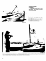
AN IMPORTANT MAINTENANCE PROCEDURE:
line around a shroud, under the boom and around
the other shroud. Tightening this line will tighten the
shrouds and minimize fatigue and wear. Another
method is to install a shroud tension adjuster (a
single line tied to the bridle intersection and run
through a cleat near the mast on the front cross bar).
Tightening the shroud adjuster will tighten the shrouds.
Any metal part when exposed to salt water, salt
spray, or even salt air, no matter how well protected,
can subsequently oxidize and become weakened. In
designing and building the Hobie Ca~ we have taken
every care to slow down and therefore minimize the
adverse effects of corrosion. The aluminum extrusions
used on the boat are all anodized and our casting
are co~ted wi:h either coricone or acrylic, both
protective coatings.
Nonetheless, no matter how thoroughly the metal is
protected,
corrosion
can. take ~Iace in time.
Consequently,
the following
maintenance
and
inspection procedures are recommended.
TOWING TIPS FOR
THE HOBIE CAT@ TRAILER SAILOR
DANGER!
Extreme caution must be observed when launching
and sailing near overhead wires. A mast near a
wire could be fatal!
For a large percentage of Hobie Ca~ boating enthusiasts, the boat trailer is an indispensable part of the
'. boating picture. This vehicle makes it possible to
1. If at all possible, you should wash down your"
boat with fresh water after using it in salt water
to remove any salt which greatly accelerates
enjoy n~w saili.ng scen~s e~ch w~ek,~nd and most of
~II provide an Inexpensive mooring for your favorIte cat.
corrosion when left to stand on any metal part.
2. Periodically inspect your boat's metal parts for
chafing, scratching, notching or other signs of
damage to the surface finish. Damage to the
surface finish may remove the protective coating
(anodizing, coricone or acrylic) thereby giving
corrosive elements access to the bare metal.
3. In particular, any time y~ur. boat is ~Ubject to
unusual stress, such as tipping over In the surf
or hitting something at a high speed, you should
thoroughly inspect it .for signs of stress as this
can accelerate corrosion.
MOORING:
Mooring a Hobie@ is not recommended as it will
SEL~CTING THE PROPER TRAILER.
.
T~~ Important needs ~hould be considered In dete~mining the proper trailer for your boat; the boat s
need and your needs. First, the trailer should "fit
yo~r boat," allowing equal distribution of the hull
weight.
Secondly, a trailer for a boat that is always hoisted
does not need to be as elaborate as one that is used
for water launching. In this respect, shallow shore
slopes or unimproved launch sites may call for a
"tilting,"
"breakaway"
or an extending tongue
trailer. A trailer that meets your boating needs make
launching and retrieving enjoyable and safe.
cause deterioration and discoloration of the hull. If,
however it has to be moored for a short time the
main things to remember are to make sure everything
is snug and secure, and that the hulls are protected
as much as possible against gelcoat deterioration.
A good anti-fouling paint can be applied for some
protection from marine growth before mooring. Before painting, it is suggested that the area be masked.
off to ensure a clean line. No friction reducing paints
or agents may be employed on a Hobie Ca~ during
competition.
Obviously the first thing to do is tie the boat securely
to the mooring. Then furl the sail and secure all gear
so it can't chafe when swells and boat wakes rock
and thrash the boat. Last, but very important, be
sure all shrouds are tight so the mast can't flop and
fatigue the wires in the shrouds. Many an unsuspecting boat owner has moored his boat for a few days
only to return to find his mast laying in the water.
The easiest way to tighten the shrouds is to run a
30
HITCHING YOUR TRAILER
T:ailer hitches com.e in a variety of sha~es and
~Izes. Most boat trailers conn~ct to ~ ball hitch that
IS bolted or welded to the towing vehicle. Clamp-onbumper hitches are not recommended for heavy
loads or continued towing. Special heavy-duty
equalizing hitches are a necessity for trailer tongue
weights (the weight a loaded trailer places on the
hitch of the towing vehicle) of 250 pounds or greater.
The trailer hitch itself should match the size of the
ball hitch: NEVER use a ball hitch that is too small.
Solid steel ball hitches are preferable.
The coupling hitch on the trailer should have a lock
or provisions to prevent loosening due to vibration.
Lubricate the hitch for longer wear and quiet turns.
The trailer should be equipped with at least one,
preferably two safety chains. The chain must have a
breaking strength of at least the gross weight of the
trailer; solid link chain is best. Safety chains should
be connected to the frame of the towing vehicle
whenever the trailer is in use.
CAUTION: Boat and mast should be securely
attached to trailer with adequate tie down straps.
Failure to do so could cause extensive damage or
serious injury!
LOADING YOUR TRAILER
The weight of the boat, equipment and additional
gear should never exceed the manufacturer's rated
weight capacity. Proper distribution of the load is of
vital importance. Too much weight on the hitch will
cause "tail dragging" of the towing vehicle, impairing
steering and raising headlights into the eyes of
oncoming traffic. Too little or negative weight on the
hitch, and the trailer will sway or "fishtail". The solution to proper distribution is often adjusting movable
gear.
TOWING
Extra caution is necessary when towing any trailer.
The heavier the rig, the more time required to
accelerate, pass, and stop. For this reason, the
maximum speed for vehicles with trailers is less
than without a trailer in most states. A long rig
requires a larger turning radius. Curbs and obstructions should be given wide clearance. Most boats
o~ trailers obstruct th~:ear view o! the d~iver. When
t~IS h~ppens, an ad~ltlonal ~ear .vlew ~Irror on the
right sl~e of the towing vehicle IS r~~ulre~ by lav:"
The t~aller boatman s~ould be famlll,ar with t~afflc
and .hlghway I.a:s relating .to the towing of trailers.
Towing ~ Hoble
has .P:rtl~ular haza~ds that should
be mentlon.ed. A Hoble
IS very wide. Obstac!es
should be given ~Ienty of ro~m when you are pass~ng
them. Fo.r long distance towing to prevent exce~slve
drag, or In ~reas exposed to strong or gusty winds,
the tr~mpoll.ne should be unlaced and rolle~ around
the side rails to prevent the boat and trailer from
being blown over. Hobie@ tie down straps or
lashings should be of sufficient size and diameter
and placed on all four corners.
The mast support on a trailer is subject to a lot of
side-to-side motion and consequently may fatigue
where it is welded to to the trailer. All this can be
reduced by tying a line from each bow to the mast
support. This will stiffen the rig up and prolong the
life of the trailer.
LAUNCHING AND RETRIEVING
Prepare boat for launching at the top of the ramp or
parking facility. Remove all tie-down straps, check
boat plugs and fasten boat painter. Do not release
winch line until boat is in the water. Back trailer to
the left if possible; backing left gives better
launching visibility. Avoid dunking wheel bearings
wherever possible. Never leave the' towing vehicle
unattended on the ramp with only the parking brake
set. If vehicle must be left while on the ramp, set
transmission in "park" or first gear, in addition to
the parking brake. In retrieving your boat, make sure
that the boat is properly placed on the trailer. Pull
trailer up steadily to prevent spinning the wheels.
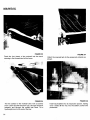
MAINTENANCE
Lights: Most state laws require two red taillights on
t~e rear that may be combined with the stop and turn
signals. Vehicles over 80 inches in width require
~Iear~nce lights. If lights are dunked:", waterproof
light fixtures should be used. If water IS allowed to
enter, the lamp may crack and short out the entire
system. Water also promotes contact corrosion.
Alw~ys car~ spare lamps. ~he wire coupling to the
towing vehicle shou~d b~ high enough to stay dry.
Never rely on the trailer hitch for ground connection.
Four-pole c.onnectors should be used.
The Hobie@ mast should not extend over three feet
behind the rear light assembly. The ideal mounting
is with the rudders up and the lights mounted to the
tiller castings, if allowed in your area.
. .
On a van rack combl~atlon the rear end of the mast
should show a red light and flag, the front of the
mast cannot extend over three feet forward of front
bumper.
Wheels: Tires should ALWAYS be inflated to manufacturer's recommended pressure. Always carry a
spare wheel and a jack that fit the boat trailer. If
wheel bearings are always dunked, waterproof
bearings and caps should be considered. If water is
allowed into the hub, lubricating grease will float
away and bearings will burn out or seize, causing
damage and a safety hazard. Waterproofed bearings
should be inspected prior to each boating season,
others more often. Special care should be given
when traveling on unimproved roadways with small
diameter wheels.
If a spare wheel is not available, a spare wheel
bearing set should be taken on long trips in case
grease seal has been broken.
FRAME AND ROLLERS
Rust should not be allowed to accumulate. Remove
rust and repaint with anti-rust paint. Some trailers
offer galvanized coating to prevent rust. Rollers
should roll freely, and should not have checks,
breaks, or flat spots.
TOWING VEHICLE
Most vehicles are limited in towing capacity. Towing
heavy loads places extra demands on the engine,
transmission, brakes and other systems vital to the
vehicle. Towing "packages" are available through
most auto dealers and should be considered for
heavy boats.
31
~
HOWE
SVNTHOT'C
F...,c.
COVTON
F...,cs
MOUNT"NOO.'NG
B'C".'C"'NG F...,cs
S.OC"LTVOUTO.WO'.F...,cs
COTTON
Duc"
F"'TO. F...,cs
V'NVLa NOO"ONOCO'TOOF...,c.
GOYO.NMONV
S.OC"'C'T'ON F...,c.
S..C,... EGY""N F...,c.
&
220
BAINBRIDGE.
COMMERCIAL.
BOSTON.
STREET
MASS, 02109.
T'L' .'7.723.8000
U, S. A,
. c..,. -HOWO."N"
VO"E' 84.0S87
INC.
B"N..'DGO ST..,..,.oo S""C"OTH'
B"N..'DGO D"'.ON S""C"OTHS
B"N..'DGO NV..ONS"LC"OTHS
FE.THO.WO'GHT
TONTF...,c.
P'.'CHUTO' a B.LLOONF...,cs
Ac.v..,cF...,cs
DO"GNO.' O. INOUST."LTO'T'..O'
'NOU.T.'... SHOOT'NG
S"..M"'O.' H'.ow,.o
"i:
WETBLEEDINGOF SAILCLOTHS
To preventcolor transferon your sails dry themas thoroughlyas possible
after using. Try not to store wet in sailbag for any longer periodsof time
than necessary.
Wheneither dyed Nylon or dyed Dacronsail fabrics are stored wet, the
color will bleedor transfer fromthe coloredto the white or even from a
darkershadeto a lighter shade. The wetter and morecompressedthe
fabric, the greaterthe bleeding such as stuffed in a sailbag.
-
HOWE1\ BAINBRIDGE,INC.
i
32
USEDBY
PERMISSI
ON-HOW
E & BAINBRIDGE,
INC.