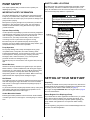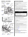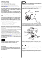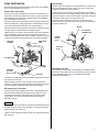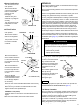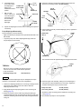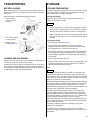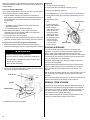
1
INTRODUCTION
Congratulations on your selection of a Honda diaphragm pump! We
are certain you will be pleased with your purchase of one of the finest
pumps on the market.
OWNER’S MANUAL
WDP30X
We want to help you get the best results from your new pump and to
operate it safely. This manual contains the information on how to do
that; please read it carefully.
We suggest you read the DISTRIBUTOR’S LIMITED WARRANTY
(page 21) and EMISSION CONTROL SYSTEM WARRANTY
(page 22) to fully understand coverage and your responsibilities of
ownership.
When your pump needs scheduled maintenance, keep in mind that an
authorized Honda servicing dealer is specially trained in servicing
Honda pumps and is supported by the parts and service divisions of
American Honda. Your Honda dealer is dedicated to your satisfaction
and will be pleased to answer your questions and concerns.
Keep this owner’s manual handy, so you can refer to it at any time.
This owner’s manual is considered a permanent part of the pump and
should remain with the pump if resold.
The information and specifications included in this publication were in
effect at the time of approval for printing. American Honda Motor Co.,
Inc. reserves the right, however, to discontinue or change
specifications or design at any time without notice and without
incurring any obligation whatever. No part of this publication may be
reproduced without written permission.
SAFETY MESSAGES
Your safety and the safety of others are very important. We have
provided important safety messages in this manual and on the pump.
This information alerts you to potential hazards that could hurt you or
others. Please read these messages carefully.
Of course, it is not practical or possible to warn you about all the
hazards associated with operating or maintaining a diaphragm pump.
You must use your own good judgment.
You will find important safety information in a variety of forms:
• Safety Labels – on the pump.
• Instructions – how to use this pump correctly and safely.
• Safety Messages – preceded by a safety alert A symbol and one
of three signal words: DANGER, WARNING, or CAUTION. These
signal words mean:
B DANGER
You WILL be KILLED or SERIOUSLY
HURT if you don't follow instructions.
B WARNING
You CAN be KILLED or SERIOUSLY
HURT if you don't follow instructions.
B CAUTION
You CAN be HURT if you don't follow
instructions.
Each message tells you what the hazard is, what can happen, and
what you can do to avoid or reduce injury.
• Damage Prevention Messages – You will also see other
important messages that are preceded by the word NOTICE. This
word means:
NOTICE
B
WARNING:
B
The engine exhaust from this product contains
chemicals known to the State of California to cause
cancer, birth defects, or other reproductive harm.
CONTENTS
PUMP SAFETY .................................2 TECHNICAL INFORMATION ......... 17
SAFETY LABEL LOCATIONS ......2
SERIAL NUMBER LOCATIONS. 17
CARBURETOR
SETTING UP YOUR NEW PUMP .....2
MODIFICATION FOR HIGH
CONTROL LOCATIONS...................3
ALTITUDE OPERATION ............ 17
BEFORE OPERATION .....................3
EMISSION CONTROL SYSTEM 18
IS YOUR PUMP READY TO GO? 3
AIR INDEX.................................. 18
OPERATION .....................................4
SPECIFICATIONS...................... 18
SAFE OPERATING
CONSUMER
INFORMATION ......... 20
PRECAUTIONS
4
REPLACEMENT PARTS,
PUMP PREPARATION.................5
OPTIONAL EQUIPMENT, AND
STARTING THE ENGINE.............6
SERVICE ITEMS ........................ 20
STOPPING THE ENGINE ............6
DEALER LOCATOR
SERVICING YOUR PUMP ................7
INFORMATION........................... 20
MAINTENANCE SAFETY.............7
CUSTOMER SERVICE
MAINTENANCE SCHEDULE .......7
INFORMATION........................... 20
ENGINE MAINTENANCE .............8
DISTRIBUTOR'S LIMITED
REFUELING ...............................11
WARRANTY ............................... 21
PUMP MAINTENANCE ..............12
HONDA PARTS, ACCESSORIES,
AND APPAREL .......................... 21
TRANSPORTING ............................15
EMISSION CONTROL SYSTEM
STORAGE .......................................15
WARRANTY ............................... 22
TAKING CARE OF UNEXPECTED
PROBLEMS ....................................17
Your pump or other property can be damaged
if you don’t follow instructions.
© 1996–2011 American Honda Motor Co., Inc.—All Rights Reserved
31TDP614
00X31-TDP-6140
EM5
K2
POM31TDP614
AHM.300.2011.11
PRINTED IN U.S.A.
1
PUMP SAFETY
SAFETY LABEL LOCATIONS
This chapter explains what you need to know to operate your
diaphragm pump safely.
The label shown here contains important safety information. Please
read it carefully. This label is considered a permanent part of your
pump. So if the label comes off or becomes hard to read, contact your
authorized Honda pump dealer for a replacement.
IMPORTANT SAFETY INFORMATION
The Honda WDP30X pump is not designed to pump drinking water.
Pump only non-potable water, muddy water, and water containing
solids. Other uses can result in injury to the operator or damage to the
pump and other property.
Gasoline is highly flammable and explosive.
Turn engine off and let cool before refueling.
The engine emits toxic carbon monoxide.
Do not run in an enclosed area.
Read owner’s manual before operation.
Thai Honda Mfg. Co. Ltd. Made in Thailand
Most injuries or property damage can be prevented if you follow all
instructions in this manual and on the pump. The most common
hazards are discussed below, along with the best way to protect
yourself and others.
CAUTION
Operator Responsibility
HOT MUFFLER CAN
BURN YOU.
Stay away if engine
has been running.
It is the operator's responsibility to provide the necessary safeguards
to protect people and property. Know how to stop the pump quickly in
case of emergency. Understand the use of all controls and
connections. For your safety and the safety of others, keep the
connecting rod cover in place when the engine is running.
Be sure that anyone who operates the pump receives proper
instruction. Do not let children operate the pump. Keep children, pets,
and bystanders away from the area of operation.
Pump Operation
Do not pump drinking water. Pumps are designed to only pump
non-potable water, muddy water, and water containing solids.
Pumping flammable liquids, such as gasoline or fuel oils, can result in
a fire or explosion, causing serious injury. Pumping sea water,
beverages, acids, chemical solutions, or any other liquid that
promotes corrosion can damage the pump.
Operate the pump on a level surface. If the engine is tilted, fuel may
spill.
Refuel With Care
Gasoline is extremely flammable, and gasoline vapor can explode.
Refuel outdoors, in a well-ventilated area, with the engine stopped
and the pump on a level surface. Do not overfill the fuel tank. Never
smoke near gasoline, and keep other flames and sparks away.
Always store gasoline in an approved container. Make sure that any
spilled fuel has been wiped up before starting the engine.
Hot Exhaust
SETTING UP YOUR NEW PUMP
The muffler becomes very hot during operation and remains hot for a
while after stopping the engine. Be careful not to touch the muffler
while it is hot. Let the engine cool before transporting the pump or
storing it indoors.
Unpacking
To prevent fire hazards, keep the pump at least 3 feet (1 meter) away
from building walls and other equipment during operation. Do not
place flammable objects close to the engine.
Carbon Monoxide Hazards
Exhaust gas contains poisonous carbon monoxide. Avoid inhalation
of exhaust gas. Never run the engine in a closed garage or confined
area.
The handle is installed over the pump for shipment only. Remove the
handle release pin and reinstall the handlebar facing outward for ease
of handling. Secure with the handle release pin (page 3).
The engine is shipped WITHOUT OIL in the engine. Refer to page 8
for oil recommendations.
Please Register Your Diaphragm Pump
If your dealer did not collect registration information from you, please
take a few minutes and register your purchase with Honda. This
allows us to contact you with any important updates regarding your
pump. Please note registration is not required to obtain warranty
service.
You can register by going online to www.HondaPowerEquipment.com
and click on Product Registration.
2
CONTROL LOCATIONS
GEAR BOX OIL FILLER
CAP/DIPSTICK (p. 12)
BEFORE OPERATION
Your safety is your responsibility. A little time spent in preparation will
significantly reduce your risk of injury.
GEAR BOX DRAIN
BOLT (Remove
connecting rod
cover) (p. 12)
MUFFLER
FUEL CAP
AIR CUSHION
CHAMBER CAP
(Priming filler
cap) (p. 5)
Read and understand this manual. Know what the controls do and
how to operate them.
Familiarize yourself with the pump and its operation before you begin
using it. Know how to quickly shut off the engine in case of an
emergency.
Be sure of what you are pumping. This pump is designed to pump
only non-potable water, muddy water, and water containing solids.
AIR
CLEANER
(p. 9)
SPARK
PLUG CAP
IS YOUR PUMP READY TO GO?
For your safety, and to maximize the service life of your equipment, it
is very important to take a few moments before you operate the pump
to check its condition. Be sure to take care of any problem you find, or
have your servicing dealer correct it, before you operate the pump.
(p. 10)
B WARNING
Improperly maintaining this pump, or failing to correct a
problem before operation, could cause a malfunction in which
you could be seriously injured.
STARTER
GRIP
SUCTION
PORT (p. 5)
Always perform a pre-operation inspection before each
operation, and correct any problem.
THROTTLE LEVER
Before beginning your pre-operation checks, be sure the pump is on a
level surface and the ignition switch is in the OFF position.
CHOKE LEVER
Check the General Condition of the Pump
FUEL
VALVE LEVER
• Look around and underneath the pump for signs of oil or gasoline
leaks.
• Remove any dirt or debris, especially around the engine, muffler,
and recoil starter.
• Look for signs of damage.
LIFTING
BRACKET
PUMP GREASE FITTING
ACCESS PLUG (p. 12)
• Check that all nuts, bolts, screws, hose connectors, and clamps are
tightened.
• Keep the connecting rod cover in place while operating the pump.
Check the Suction and Discharge Hoses
HANDLE
HANDLE
RELEASE PIN
DISCHARGE
PORT (p. 5)
• Check the general condition of the hoses. Be sure the hoses are in
serviceable condition before connecting them to the pump.
Remember that the suction hose must be of reinforced construction
to prevent hose collapse.
• Check that the sealing washer in the suction hose connector is in
good condition (page 12).
• Check that the strainer is in good condition and is installed on the
suction hose (page 12).
Check the Engine
• Check the oil level (page 8). To avoid the inconvenience of an
unexpected shutdown by the Oil Alert® system, always check the
engine oil level before startup.
• Check the air cleaner (page 9).
ENGINE OIL FILLER
CAP/DIPSTICK (p. 8)
IGNITION SWITCH
(p. 6)
• Check the fuel level (page 11). Starting with a full tank will help to
eliminate or reduce operating interruptions for refueling.
ENGINE OIL DRAIN
BOLT (p. 8)
3
OPERATION
SAFE OPERATING PRECAUTIONS
Before operating the pump for the first time, please review
IMPORTANT SAFETY INFORMATION (page 2) and BEFORE
OPERATION (page 3).
For your safety, avoid starting or operating the engine in an enclosed
area, such as a garage. Your engine’s exhaust contains poisonous
carbon monoxide gas, which can collect rapidly in an enclosed area
and cause illness or death.
NOTICE
Due to pump movement during operation, connecting a rigid pipe to
the pump will cause pump damage. Always use flexible suction and
discharge hoses to prevent pump damage.
When water being pumped contains solids, the solids may get lodged
under the clappet valves, which will prevent the clappet valves from
closing completely. To maintain maximum pump performance, the
discharge hose should angle upward as it exits the pump.
DISCHARGE
HOSE
Do not pump drinking water. Pump only non-potable water, muddy
water, and water containing solids. Pumping flammable liquids, such
as gasoline or fuel oils, can result in a fire or explosion, causing
serious injury. Pumping sea water, beverages, acids, chemical
solutions, or any other liquid that promotes corrosion can damage the
pump.
Due to the pump diaphragm reciprocating motion, pump assembly
and hoses will move up and down and side-to-side during pumping.
This may cause the pump to walk or move around while pumping.
Depending on the surface conditions, pump hose length, and other
factors, it may be necessary to anchor the pump to limit pump
movement. During operation, observe pump movement and anchor
the pump frame and wheels as necessary.
• Attach anchored tie-down straps to the pump frame.
• Place blocks in front and behind the wheels.
• Try to locate the pump on a level surface.
While pumping, the suction hose may move out of the pumping
source, and the discharge hose may move away from the pumping
destination. It may also be necessary to anchor hose ends to prevent
hose movement.
If the discharge hose must run across a roadway, the hose should
cross the roadway perpendicular to traffic flow. Also, heavy boards
should be placed next to the hose so the motor vehicle weight does
not shut off the discharge as vehicles cross over the hose.
If there is no one to monitor the pump during operation, it is advisable
to anchor the pump to prevent unexpected movement.
Pump total dynamic discharge head is 50 feet. Total dynamic
discharge head includes static discharge head (discharge vertical
height) and head loss due to friction. Head loss makes it impractical
for the static discharge head to exceed 25 feet. Pumping to a static
discharge head greater than 25 feet can damage the pump. See the
Pump Performance Curve on page 19.
BOARDS
DISCHARGE
HOSE
This diaphragm pump should never be run with the discharge output
shut off or restricted.
NOTICE
Pump case failure may result if the discharge output is shut off or
restricted. To avoid pump damage, do not restrict, shut off, or
momentarily stop the fluid flow from the discharge hose.
A rigid pipe should never be used with a diaphragm pump. Flexible
hoses must be attached to the pump. The suction hose must be noncollapsible. Never use hoses that are smaller than the suction or
discharge fittings.
This pump requires a 3 inch inside diameter or larger hose. Using
rigid pipes or hoses that are too small will cause severe damage to
the diaphragm pump.
Driving over a discharge hose while the pump is running, or even
possibly when the pump is stopped, will most likely cause pump case
failure.
NOTICE
Collapsing the discharge hose will cause pump case and/or
diaphragm damage. To prevent pump damage, take the necessary
precautions to prevent the discharge hose from getting compressed
or collapsed.
During freezing weather, always drain the pump case after use. If
water is left in the pump case during freezing weather, the pump case
will break.
4
PUMP PREPARATION
Pump Priming
Optional hose kits, designed specifically for this pump, are available
from your Honda dealer. See page 20.
Pump priming is not required if the vertical distance from water to the
pump (suction head) is less than 16 feet. The suction head can be
increased to 24 feet if the pump is primed.
Suction Hose Connection
To prime the pump, remove the air cushion chamber cap. Grasp the
suction hose next to the suction fitting and lift the hose about 1 foot off
the ground. Lifting the suction hose will help to ensure the water goes
into the pump housing and not out the suction hose.
If using a commercially available hose, ensure it is the same size or
larger than the suction port diameter (3 inches). To prevent the hose
from collapsing, use a hose that is reinforced with a non-collapsible
wall or braided wire construction.
Keep the pump as close as possible to the pumping liquid. Avoid hose
bends and sharp turns. Pump performance is best when the pump is
not far above the liquid level and the hose is kept straight.
Pour about 1 gallon of water into the pump case through the air
cushion chamber. Lay the hose back on the ground, and reinstall the
air cushion chamber cap.
WATER
Self-priming time is also proportional to the suction hose length. Using
a longer suction hose will increase the self-priming time.
Tighten the hose connector to the suction hose with a hose clamp to
prevent air leakage and loss of suction. Verify that the connector
sealing washer is installed and in good condition. A loosely connected
suction hose will reduce pump performance and self-priming ability.
SEALING
WASHER
DISCHARGE
HOSE
AIR CUSHION
CHAMBER CAP
PRIMING
FILLER
HOLE
SUCTION
HOSE
SUCTION HOSE
HOSE
CLAMP
STRAINER
(provided
with the pump)
COUPLING
FREQUENCY OF USE
If your equipment will be used on an infrequent or intermittent basis,
(more than 4 weeks before next use), please refer to the Fuel section
of the STORAGE chapter (page 15) for additional information
regarding fuel deterioration.
The strainer provided with the pump should be attached to the end of
the suction hose as shown.
Always install the strainer on the end of the suction hose before
pumping. The strainer will prevent debris from entering the pump that
can cause clogging, diaphragm and/or other pump damage.
Discharge Hose Connection
If using a commercially available hose, a short, large diameter hose
will provide lower fluid friction and improve pump output. A long or
small diameter hose will increase fluid friction and reduce pump
output. Never use a hose size smaller than the discharge port
diameter (3 inches).
NOTICE
If a discharge hose is used that has a smaller inside diameter than the
port size, the pump case may be damaged. To avoid pump damage,
always use the correct size hose.
Tighten the hose clamp to prevent the hose from disconnecting under
high pressure.
5
STARTING THE ENGINE
5. Pull the starter grip
lightly until resistance
is felt, then pull it
briskly.
1. Turn the fuel valve to the ON position.
FUEL VALVE
NOTICE
Return the starter grip
slowly back to the
engine to prevent
damage to the starter.
ON
6. As the engine warms
up, gradually move
the choke lever to the
OPEN position.
……ON
STARTER GRIP
CHOKE LEVER
2. Move the choke lever to the CLOSED position.
Do not use the choke if the engine is warm or the ambient
temperature is high.
OPEN
CHOKE LEVER
7. Set the throttle to the
desired speed to
produce the best
pumping conditions.
CLOSE……
THROTTLE LEVER
Pump output can be
controlled by adjusting
the throttle lever to the
desired position.
CLOSE
3. Turn the ignition switch to the ON position.
IDLE
FULL
IGNITION SWITCH
ON
At FULL throttle position, the pump will deliver the highest output
volume. Moving the throttle toward the IDLE position will decrease
the output volume of the pump.
ON
ON
STOPPING THE ENGINE
Emergency
To stop the engine in an
emergency, turn the
ignition switch to the OFF
position.
IGNITION
SWITCH
OFF
ON
4. Move the throttle control lever slightly to the left.
Normal
1. Move the throttle lever
fully to the right to the
IDLE position.
THROTTLE LEVER
HIGH
LOW
2. Turn the ignition switch
to the OFF position.
THROTTLE LEVER
IDLE
3. Turn the fuel valve to
the OFF position.
4. After each use, drain
the pump chamber and
flush with fresh water
(page 12).
5. If your equipment will not be used for 3 to 4 weeks, we recommend
running the engine’s carburetor out of fuel. You can do this by
leaving the fuel valve OFF, restarting the engine and running it out
of fuel. See ”STORAGE PREPARATION” on page 15. for periods
of inactivity that exceed 4 weeks.
6
SERVICING YOUR PUMP
Proper maintenance is essential for safe, economical, and
trouble-free operation. It will also help reduce air pollution.
B WARNING
Improper maintenance, or failure to correct a problem
before operation, can cause a malfunction in which you
can be seriously hurt or killed.
Always follow the inspection and maintenance
recommendations and schedules in this owner’s manual.
To help you properly care for your pump, the following pages include
a maintenance schedule, routine inspection procedures, and simple
maintenance procedures using basic hand tools. Other service tasks
that are more difficult, or require special tools, are best handled by
professionals and are normally performed by a Honda technician or
other qualified mechanic.
The maintenance schedule applies to normal operating conditions. If
you operate your pump under severe conditions, such as sustained
high-load or high-temperature operation, or use in unusually wet or
dusty conditions, consult your servicing dealer for recommendations
applicable to your individual needs and use.
Safety Precautions
• Make sure the engine is off before you begin any maintenance or
repairs. This will eliminate several potential hazards:
• Carbon monoxide poisoning from engine exhaust.
Be sure there is adequate ventilation whenever you operate
the engine.
• Burns from hot parts.
Let the engine and exhaust system cool before touching.
• Injury from moving parts.
Do not run the engine unless instructed to do so.
• Read the instructions before you begin, and make sure you have
the tools and skills required.
• To reduce the possibility of fire or explosion, be careful when
working around gasoline. Use only a nonflammable solvent, not
gasoline, to clean parts. Keep cigarettes, sparks, and flames away
from all fuel-related parts.
MAINTENANCE SCHEDULE
Interval
Item
Before each use
Check the engine oil level (page 8)
Check the air filter (page 9)
Check pump hoses and strainer (page 12)
Remember that an authorized Honda servicing dealer knows your
pump best and is fully equipped to maintain and repair it.
After each use
Flush the pump chamber (page 12)
To ensure the best quality and reliability, use only new, Honda
Genuine parts or their equivalents for repair and replacement.
First month or
20 hours
Maintenance, replacement, or repair of the emission control
devices and systems may be performed by any engine repair
establishment or individual, using parts that are “certified” to
EPA standards.
Change the engine oil (page 8)
Grease the pump connecting rod bearing
(page 12)
Every 3 months or
50 hours
Clean the air filter 1 (page 9)
Clean the sediment cup (page 11)
Grease the pump connecting rod bearing
(page 12)
Check the gear box oil level (page 12)
Every 6 months or
100 hours
Change the engine oil 1 (page 8)
Inspect-adjust the spark plug (page 10)
Clean-check the spark arrester (page 10)
(optional equipment)
MAINTENANCE SAFETY
Some of the most important safety precautions follow. However, we
cannot warn you of every conceivable hazard that can arise in
performing maintenance. Only you can decide whether or not you
should perform a given task.
B WARNING
Every year or
300 hours
Change the engine oil 1 (page 8)
Replace the air cleaner paper filter 1 (page 9)
Replace the spark plug (page 10)
Adjust the valve clearance 2
Adjust the idle speed 2
Clean the fuel tank and filter 2
Change the gear box oil (page 12)
Inspect the pump clappet valve (page 13)
Inspect the pump diaphragm (page 13)
Check the torque of nuts and bolts
Every 2 years
Check the fuel line and replace if necessary 2
Failure to properly follow maintenance instructions and
precautions can cause you to be seriously hurt or killed.
Always follow the procedures and precautions in this
owner’s manual.
1. Service more frequently when used in dusty areas.
2. These items should be serviced by an authorized Honda servicing
dealer, unless you have the proper tools and are mechanically
proficient.
Failure to follow this maintenance schedule could result in
non-warrantable failures.
7
ENGINE MAINTENANCE
2. Reinstall the drain bolt and sealing washer. Tighten the bolt
securely.
Engine Oil Level Check
Check the engine oil level with the engine stopped and in a level
position.
1. Remove the filler cap/dipstick and wipe it clean.
NOTICE
Improper disposal of engine oil can be harmful to the environment.
If you change your own oil, please dispose of the used oil properly.
Put it in a sealed container, and take it to a recycling center. Do not
discard it in a trash bin, dump it on the ground, or pour it down a
drain.
3. Fill with the recommended oil to the top of the oil filler neck.
Quantity: 0.6 qt (0.6 l)
4. Screw in the filler cap/dipstick securely.
FILLER CAP/DIP
STICK
2. Insert and remove the dipstick without screwing it into the filler
neck. Check the oil level shown on the dipstick.
UPPER LIMIT
MARK
FILLER
CAP/DIPSTICK
UPPER LIMIT
TOP OF OIL
FILLER NECK
Engine Oil Recommendations
LOWER LIMIT
3. If the oil level is low, fill to the edge of the oil filler hole with the
recommended oil (see page 8).
4. Screw in the filler cap/dipstick securely.
NOTICE
Running the engine with a low oil level can cause engine damage.
The Oil Alert system will automatically stop the engine before the oil
level falls below the safe limit. However, to avoid the inconvenience of
an unexpected shutdown, always check the engine oil level before
startup.
Engine Oil Change
Drain the oil while the engine is warm. Warm oil drains quickly and
completely.
1. Remove the filler cap/dipstick, drain bolt, and sealing washer.
Drain the oil into a suitable container.
FILLER
CAP/DIPSTICK
SEALING
WASHER
DRAIN
BOLT
8
Oil is a major factor affecting
performance and service life. Use
4-stroke automotive detergent oil.
SAE 10W-30 is recommended for
general use. Other viscosities
shown in the chart may be used
when the average temperature in
your area is within the
recommended range.
30
5W-30 • 10W-30
0
20
-20 -10
40
0
60
10
20
80 100°F
30
40°C
The SAE oil viscosity and service category are in the API label on the
oil container. Honda recommends that you use API service category
SJ or later oil.
NOTICE
Using nondetergent oil can shorten the engine's service life, and using
2-stroke oil can damage the engine.
Air Filter Inspection
Air Filter Cleaning
1. Unscrew the outer wing nut and remove the air cleaner cover.
A properly maintained air filter will help prevent dirt from entering your
engine. Dirt entering the carburetor can be drawn into small passages
in the carburetor and cause premature engine wear. These small
passages can become blocked, causing starting or running problems.
Always use an air filter specified for your engine to ensure it seals and
performs as designed. You will need to clean the filter more frequently
if you operate the engine in very dusty conditions.
OUTER
WING NUT
AIR CLEANER
COVER
INNER
WING NUT
PAPER FILTER
ELEMENT
FOAM FILTER
ELEMENT
RUBBER
WASHER
1. To clean the paper filter element, tap the element lightly several
times on a hard surface to remove excess dirt, or blow compressed
air [not exceeding 30 psi (207 kPa)] through the filter element from
the inside out.
Never try to brush the dirt off; brushing will force dirt into the paper
fibers. Replace the paper element if it is excessively dirty or
damaged.
2. To clean the foam filter
element, wash the
element in a solution of
household detergent and
warm water, then rinse
thoroughly, or wash in
nonflammable solvent.
3. Allow the foam filter
element to dry
thoroughly.
SOLVENT
ENGINE OIL
SQUEEZE
THOROUGHLY
4. Soak the foam filter element in clean engine oil and squeeze out
the excess oil.
2. Remove the inner wing nut and both air filter elements.
3. Separate both air filter elements and carefully check them for holes
or tears. Replace the filter elements if they are damaged.
4. If the air filter elements are dirty, clean them as described below.
5. Wipe dirt from the inside of the air cleaner housing and cover. Be
careful to prevent dirt from entering the air duct that leads to the
carburetor.
NOTICE
Excess oil will restrict air flow through the foam filter element and
may transfer to the paper filter element, soaking and clogging it.
5. Reassemble the air filter as shown.
6. Install the foam element over the paper element, and install the
assembled air filter. Secure the air filter with the inner wing nut.
Make sure the rubber washer is in place under the filter elements.
7. Install the air cleaner cover, and secure with the outer wing nut.
NOTICE
Operating the engine without an air filter, or with a damaged air
filter, will allow dirt to enter the engine, causing rapid engine wear.
This type of damage is not covered by the DISTRIBUTOR'S
LIMITED WARRANTY.
9
Spark Plug Service
Spark Arrester (optional equipment)
Recommended Spark Plug: NGK - BPR6ES
Your pump engine is not factory-equipped with a spark arrester. In
some areas, it is illegal to operate an engine without a spark arrester.
Check local laws and regulations. An optional USDA approved spark
arrester is available from an authorized Honda servicing dealer. See
page 20 for part numbers.
NOTICE
Incorrect spark plugs can cause engine damage.
For good performance, the spark plug must be properly gapped and
free of deposits.
The spark arrester must be serviced every 100 hours to keep it
functioning as designed.
Allow the engine to cool before servicing the spark plug.
1. Allow the engine to cool, then remove the two 8 mm nuts and
remove the muffler from the cylinder head.
1. Disconnect the spark
plug cap and remove
any dirt from around
the spark plug area.
2. Remove the four 5 mm screws from the muffler protector and
remove the muffler protector.
SPARK PLUG WRENCH
3. Remove the 4 mm screw from the spark arrester and remove the
spark arrester from the muffler.
2. Use a 13/16 in
(21 mm) spark plug
wrench to remove the
spark plug.
MUFFLER
PROTECTOR
3. Visually inspect the
spark plug. Discard it if
the insulator is
cracked, chipped, or
fouled.
5 mm SCREW (4)
4 mm SCREW
8 mm NUT (2)
SPARK
ARRESTER
SPARK PLUG CAP
4. Measure the plug gap
with a suitable gauge.
Correct as necessary
by carefully bending
the side electrode.
Plug gap:
0.028 ~ 0.031 in
(0.70 ~ 0.80 mm)
0.028 ~ 0.031 in
(0.70 ~ 0.80 mm)
MUFFLER
SEALING
WASHER
4. Use a stiff brush to remove
carbon deposits from the spark
arrester screen. Be careful not
to damage the spark arrester
screen.
5. Inspect the spark arrester for
breaks and holes. Replace it if
necessary.
5. Check that the spark
plug washer is in good
condition, and thread the
spark plug in by hand to
prevent cross-threading.
6. After the spark plug is
seated, tighten with a
spark plug wrench to
compress the washer.
If installing a new spark plug, tighten 1/2 turn after the spark plug
seats to compress the washer.
If reinstalling a used spark plug, tighten 1/8 - 1/4 turn after the
spark plug seats to compress the washer.
NOTICE
A loose spark plug can overheat and damage the engine.
Overtightening the spark plug can damage the threads in the
cylinder head.
7. Reconnect the spark plug cap.
10
6. Install the spark arrester and the
muffler in the reverse order of
disassembly.
SPARK ARRESTER SCREEN
Carburetor Adjustment
1. Start the engine
outdoors and let it warm
up to normal operating
temperature.
2. Move the throttle lever
to the idle position
(page 6).
3. Using a screwdriver,
turn the throttle stop
screw to obtain the
standard idle speed.
Standard Idle Speed:
+200
1,400 -150
rpm
THROTTLE STOP SCREW
REFUELING
Sediment Cup Cleaning
1. Turn the fuel valve to the
OFF position.
FUEL
VALVE
2. Remove the sediment
cup and O-ring and wash
them in nonflammable
solvent. Dry them
thoroughly.
This engine is certified to operate on unleaded gasoline with a pump
octane rating of 86 or higher.
OFF
ON
We recommend refueling after each use to minimize the air present in
the fuel tank.
Refuel in a well-ventilated area with the engine stopped. If the engine
has been running, allow it to cool first. Never refuel the engine inside a
building where gasoline fumes may reach flames or sparks.
3. Install the O-ring and
sediment cup and tighten
securely.
O-RING
4. Turn the fuel valve to the
ON position and check
for leaks.
SEDIMENT CUP
Fuel Filter/Fuel Line
1. Turn the fuel valve to the
OFF position.
FUEL VALVE
ON
OFF
If your equipment will be used on an infrequent or intermittent basis
(more than 4 weeks before next use), refer to the Fuel section of the
STORAGE chapter (page 15) for additional information regarding fuel
deterioration.
2. Remove the carburetor
drain screw and gasket.
3. Turn the fuel valve to the
ON position and drain
the fuel into a suitable
container.
You may use regular unleaded gasoline containing no more than 10%
ethanol (E10) or 5% methanol by volume. In addition, methanol must
contain cosolvents and corrosion inhibitors. Use of fuels with content
of ethanol or methanol greater than shown above may cause starting
and/or performance problems. It may also damage metal, rubber, and
plastic parts of the fuel system. In addition, ethanol is hygroscopic,
which means it attracts and retains water in the fuel system. Engine
damage or performance problems that result from using a fuel with
percentages of ethanol or methanol greater than shown above are not
covered by warranty.
B WARNING
GASKET
Gasoline is highly flammable and explosive.
You can be burned or seriously injured when handling fuel.
• Stop the engine and keep heat, sparks, and flame away.
• Handle fuel only outdoors.
DRAIN SCREW
4. Disconnect the fuel line
at the carburetor. Remove
the two 6 mm nuts and one
6 x 25 mm bolt securing
the fuel tank. Remove the
fuel tank.
5. Disconnect the fuel line
from the fuel filter, and
unscrew the fuel filter from
the tank. Inspect the fuel
line and replace if cracked
or worn.
6. Clean the filter with
nonflammable solvent, and
check that the filter screen
is not damaged. Replace
as necessary.
• Wipe up spills immediately.
Never use stale or contaminated gasoline or an oil/gasoline mixture.
Avoid getting dirt or water in the fuel tank.
6 mm NUT (2)
6 x 25 mm
BOLT
O-RING
To refuel, remove the fuel tank
cap, and fill the tank with
gasoline to the shoulder of the
filler neck. Refuel carefully to
avoid spilling fuel. Do not
overfill.
FUEL FILTER
After refueling, tighten the fuel
tank cap securely.
FUEL LINE
(carburetor end)
Move the pump at least 10 feet
(3 meters) away from the
fueling source and site before
starting the engine.
7. Clean the inside of the tank with nonflammable solvent and dry
thoroughly.
8. Place the O-ring on the filter and install the filter in the tank.
Tighten the filter to the specified torque.
TORQUE: 17 in-lb (2 N•m)
9. Install the fuel line on the fuel filter, and install the tank on the
engine.
10.After the tank is installed, add fuel and check for leaks.
FUEL CAP
MAX
FUEL
LEVEL
NOTICE
Fuel can damage paint and plastic. Be careful not to spill fuel when
filling your fuel tank. Damage caused by spilled fuel is not covered by
the DISTRIBUTOR’S LIMITED WARRANTY (page 21).
Fuel Storage Container
Store your gasoline in a clean, plastic, sealed container approved for
fuel storage. Close the vent (if equipped) when not in use, and store
the container away from direct sunlight. If it will take more than 3
months to use the fuel in the container, we suggest adding a fuel
stabilizer to the fuel when you fill the container.
If you have some fuel left in your storage container at the end of the
season, the Environmental Protection Agency (EPA) recommends
adding the gasoline to your vehicle's gas tank
(http://epa.gov/reg5oair/mobile/winter.html).
11
PUMP MAINTENANCE
Pump Gear Box Oil Change
Pump Chamber Flushing
1. Run the engine for 10 minutes to warm up the gear box oil. Warm
oil drains quickly and completely.
With the engine stopped, the pump case should be flushed after each
use to prevent sediment from building up in the case.
2. Shut off the engine.
1. Disconnect the suction and discharge hoses.
3. Remove the two 8 x 15 mm bolts and washers from the connecting
rod cover and remove the cover.
2. Insert a garden hose into the suction side of the pump. Turn on the
water and thoroughly flush sediment out the discharge side.
CONNECTING
ROD COVER
OIL FILLER CAP/
DIPSTICK
SUCTION
SIDE
DISCHARGE
SIDE
8 mm
WASHER (2)
8 x 15 mm
BOLT (2)
GARDEN
HOSE
4. Remove the drain bolt and drain the gear oil from the gear box.
3. After flushing, lift the suction side of the pump and allow water to
drain out the discharge side.
OIL FILLER CAP/
DIPSTICK
Pump Hoses and Strainer
1. Check both hoses to make
sure they are not torn or
cracked. It is especially
important that there are no
tears in the suction hose.
Tears or air leaks on the
suction side will prevent the
pump from priming properly.
UPPER LIMIT
LOWER LIMIT
STRAINER
WASHER
SEALING
WASHER
2. Inspect the suction hose
sealing washer to make sure
it is in good condition.
3. Inspect the strainer to be
sure it is not plugged or
damaged.
WASHER
SUCTION
HOSE
DRAIN BOLT
Grease the Pump Connecting Rod
1. Remove the plastic
access plug.
2. Disconnect the spark
plug cap (page 10) and
pull the starter grip until
the grease fitting is
visible in the access
opening.
5. Replace the drain bolt washer and reinstall the drain bolt.
PLASTIC ACCESS
PLUG
3. Wipe the grease fitting
clean to prevent dirt
from getting into the
bearing. Using a
manual grease gun,
pump one or two
strokes of NLGI #2
general purpose grease
into the bearing.
4. Reinstall the access plug securely.
12
6. Fill the gear box to the upper limit on the oil filler cap/dipstick.
Screw the dipstick in to measure the oil level.
Recommended oil: SAE 80W/90 GL5 Gear oil
7. Dispose of the used oil properly (page 8).
8. Reinstall the connecting rod cover.
NOTICE
Avoid getting gear oil on the diaphragm. Drain the oil into a drain
pan to prevent oil from running down the pump case onto the
diaphragm. If gear oil comes in contact with the diaphragm, the
diaphragm will be damaged.
Pump Gear Box Oil Check
With the pump cold and on a level surface, remove the oil filler
cap/dipstick. The oil level should be just below the UPPER LIMIT
mark on the dipstick. Screw the dipstick in to check the oil level.
Pump Clappet Valves
2. Turn the fuel valve lever to the OFF position (page 3).
11. After tightening the nuts, insert a screwdriver into each port and
check clappet valve operation. Clappets should operate freely
and should seal when released. If a clappet does not operate
properly, reinstall the clappet and recheck.
3. Flush the pump chamber (page 12).
12. Run the pump and check for leaks.
4. Lift the suction side of the pump and allow all the water to drain out
the discharge fitting.
Pump Diaphragm Disassembly
5. Use a 19 mm wrench and remove the nuts and flat washers from
both the suction and discharge ports.
2. Drain the fuel tank (page 16). Flush the pump chamber (page 12).
1. Disconnect the spark plug cap from the spark plug (page 3).
FLAT
WASHER (4)
NUT (4)
CLAPPET VALVE
(suction side)
1. Disconnect the spark plug cap from the spark plug (page 3).
3. Remove the plastic connecting rod cover (page 12).
Pull the starter grip to rotate the connecting rod to the down
position.
4. Remove the 4 nuts, washers, bolts, and the upper pump assembly
using a 19 mm wrench. Place the upper pump and engine
assembly to the side.
CRANK ARM
12 x 50 mm
BOLT (4)
CLAPPET VALVE
(discharge side)
6. Remove both ports. The clappet valves are directional, so when
removing the valves, note the water flow direction.
12 mm
WASHER (8)
DIAPHRAGM
ASSEMBLY
7. Inspect the ports, case sealing surfaces, and clappets for damage.
If the clappets are worn, torn, or damaged, replace them. If the
case sealing surface is damaged and cannot be cleaned, an
optional wear plate and gasket is available from your Honda water
pump dealer (page 20).
UPPER PUMP
ASSEMBLY
8. Install the clappet valves over the studs. On the discharge side,
install the flat side of the valve facing the pump housing. On the
suction side, install the flat side of the valve facing the port.
DISCHARGE
PORT
CLAPPET VALVE
(flat side facing the
pump housing)
SUCTION
PORT
LOWER CASE
12 mm
NUT (4)
CLAPPET VALVE
(flat side facing
the port)
5.
Use a 17 mm wrench and remove the bolt securing the
connecting rod to the crank arm. Wipe the rod surface clean and
use a felt tip marker to mark the outside of the connecting rod for
reassembly.
CONNECTING ROD
PORT
9.
CLAPPET
VALVE
TABS
Install both ports, making sure all clappet valve tabs are
positioned correctly.
10. Apply several drops of Hondalock 2 or equivalent thread lock to
the stud threads. Hand tighten the nuts, then torque evenly.
TORQUE: 20 ft-lb (27 N•m)
NYLON
WASHER
10 x 20 mm
BOLT
10 mm LOCK WASHER
WASHER
CRANK
ARM
13
6.
7.
If the diaphragm is
to be reused, mark
the diaphragm to
allow it to be
installed in the same
position.
With a 19 mm
wrench, remove the
4 nuts securing the
connecting rod to
the lower flange.
Remove the
diaphragm.
12 mm
NUT (4)
4. Install the connecting rod with the hardware shown below and
torque the connecting rod bolt to 40 ft-lb (54 N•m).
CONNECTING
ROD FLANGE
12 mm
WASHER (4)
DIAPHRAGM
NYLON
WASHER
WASHER
SHOULDER
10 mm
BOLT
LOWER
FLANGE
CRANK
ARM
10 mm LOCK
WASHER
8.
Inspect the diaphragm for cracks, tears, or damage and replace it
if necessary.
Pump Diaphragm Reassembly
During reassembly, note the following:
• Apply several drops of Hondalock 2 or equivalent thread lock to the
bolt threads.
5. Pull the starter grip slowly until the diaphragm pulls up against the
upper case stops.
UPPER
CASE
UPPER CASE
STOP (4)
• To prevent pump case and/or diaphragm damage, follow the
torque sequence shown below.
1
3
DIAPHRAGM
4
2
The crank arm should be approximately at the angle shown below.
CRANK
ARM
TORQUE:
Start in one corner, increasing the amount of torque
1/8 to 1/4 turn each time around until the specified
torque is achieved.
Diaphragm flange nuts
35 ft-lb (47 N•m)
NOTICE
The pump case and/or diaphragm may be damaged if the torque
sequence is not followed or the nuts are overtightened.
1. Position the diaphragm between the connecting rod flange and the
lower flange, then install the nuts and washers. Note the
diaphragm shoulder on top.
2. Apply NLGI #2 general purpose grease to the connecting rod
bearing (page 12).
3. Rotate the crank arm to the bottom by pulling the starter grip.
Install the diaphragm and connecting rod into the pump case, then
install the connecting rod with the mark made during disassembly
facing out.
14
6. Install the upper case assembly, making sure the diaphragm is
centered and not pinched between the case stops. Tighten the
hardware following the torque procedure shown.
Pump case bolts
35 ft-lb (47 N•m)
Connecting rod bolt
40 ft-lb (54 N•m)
7. Grease the pump connecting rod and install the connecting rod
cover (page 12).
8. Run and test the pump for correct operation.
TRANSPORTING
STORAGE
BEFORE LOADING
STORAGE PREPARATION
When transporting the pump, be sure to keep it upright. If the pump is
tilted or overturned, fuel may spill from the tank, which can result in a
fire hazard.
The following steps will help to keep rust and corrosion from impairing
your pump's function and appearance, and will make the engine
easier to start when you use the pump again.
Allow the engine to cool before transporting the pump.
Cleaning the Engine
1. Turn the ignition
switch to the OFF
position.
Wash the engine by hand, and be careful to prevent water from
entering the air cleaner or muffler.
OFF
NOTICE
IGNITION
SWITCH
2. Turn the fuel valve to
the OFF position.
FUEL
VALVE
3. Drain the pump
chamber (page 12).
• Using a garden hose or pressure washing equipment can force
water into the air cleaner. Water in the air cleaner will soak the
filter and can enter the carburetor or engine, causing damage.
• Water contacting a hot engine can cause damage. If the engine
has been running, allow it to cool for at least half an hour before
washing.
Cleaning the Pump
1. Flush the pump chamber (page 12).
2. Wash the pump with a garden hose or other low pressure
equipment. Keep water away from controls and all other places
that are difficult to dry, as water may promote rust.
OFF
LOADING AND UNLOADING
Roll the pump on a ramp or use a hoist connected to the lifting bracket
to load the pump on and off the transport vehicle.
Position the pump so it is level on the transport vehicle. Tie the pump
down with rope or straps attached to the frame, and place blocks in
front and behind the wheels to prevent rolling. Keep the tie-down rope
or straps away from the controls and carburetor.
3. After washing, remove as much standing water as possible with a
dry cloth. Start the engine outdoors and let it run until it reaches
normal operating temperature to evaporate any water remaining
on the engine.
4. Stop the engine and allow it to cool.
5. After the pump is clean and dry, touch up any damaged paint, and
coat other areas that may rust with a light film of oil. Lubricate
controls with a silicone spray lubricant.
Fuel
NOTICE
Depending on the region where you operate your equipment, fuel
formulations may deteriorate and oxidize rapidly. Fuel deterioration
and oxidation can occur in as little as 30 days and may cause damage
to the carburetor and/or fuel system. Please check with your servicing
dealer for local storage recommendations.
Gasoline will oxidize and deteriorate in storage. Deteriorated gasoline
will cause hard starting, and it leaves gum deposits that can clog the
small passages in the fuel system. If the gasoline in your engine
deteriorates during storage, you may need to have the carburetor, and
other fuel system components, serviced or replaced.
The length of time that gasoline can be left in your fuel tank and
carburetor without causing functional problems will vary with such
factors as gasoline blend, your storage temperatures, and whether
the fuel tank is partially or completely filled. The air in a partially filled
fuel tank promotes fuel deterioration. Very warm storage
temperatures accelerate fuel deterioration. Fuel problems may occur
within a month of inactivity, or even less if the gasoline was not fresh
when you filled the fuel tank.
If you keep a container of gasoline for refueling, be sure that it
contains only fresh gasoline.
If it will take more than 3 months to use the fuel in your storage
container, we suggest adding a fuel stabilizer to the fuel when you fill
the container.
15
Fuel system damage or engine performance problems resulting from
neglected storage preparation are not covered under the Distributor’s
Limited Warranty.
Engine Oil
1. Change the engine oil (page 8).
2. Check the air filter and clean as necessary (page 9).
Short Term Storage (30-90 days)
If your equipment will not be used for 30 to 90 days, we recommend
the following to prevent fuel-related problems:
1. Add fuel stabilizer following the manufacturer’s instructions.
When adding a fuel stabilizer, fill the fuel tank with fresh gasoline. If
only partially filled, air in the tank will promote fuel deterioration
during storage.
Note:
– All stabilizers have a shelf life and their performance will
deteriorate over time.
– Fuel stabilizers will not reconstitute stale fuel.
2. After adding a fuel stabilizer, run the engine outdoors for
10 minutes to be sure that treated gasoline has replaced the
untreated gasoline in the carburetor.
3. Turn the fuel valve to the OFF position.
4. Continue to run the engine until it stops from the lack of fuel in the
carburetor fuel bowl. Running time should be less than 3 minutes.
Long Term or Seasonal Storage (greater than 90 days)
1. Remove the carburetor drain screw with a 10 mm wrench or
screwdriver, and drain the fuel into an approved gasoline container.
B WARNING
Gasoline is highly flammable and explosive.
You can be burned or seriously injured when handling fuel.
• Stop the engine and keep heat, sparks, and flame away.
• Handle fuel only outdoors.
• Wipe up spills immediately.
4. Pour a tablespoon (5 - 10 cc) of clean engine oil into the cylinder.
5. Slowly pull the starter grip a few times to distribute the oil in the
cylinder.
6. Reinstall the spark
plug.
7. Pull the starter grip
slowly until resistance
is felt. Continue
pulling slowly until the
arrow notch on the
starter pulley aligns
with the hole on the
recoil starter. Return
the starter grip gently.
This will close the
valves so moisture
cannot enter the
engine cylinder.
HOLE
ARROW NOTCH
STARTER GRIP
PLACING IN STORAGE
If your pump will be stored with gasoline in the fuel tank and
carburetor, it is important to reduce the hazard of gasoline vapor
ignition. Select a well-ventilated storage area away from any
appliance that operates with a flame, such as a furnace, water heater,
or clothes dryer. Also avoid any area with a spark producing electric
motor, or where power tools are operated.
If possible, avoid storage areas with high humidity, because that
promotes rust and corrosion.
Unless all fuel has been drained from the fuel tank, leave the fuel
valve in the OFF position to reduce the possibility of fuel leakage.
2. Turn the fuel valve to the ON position. This will allow fuel in the fuel
tank to drain through the carburetor bowl.
Place the pump on a level surface. Tilting can cause fuel or oil
leakage.
With the engine and exhaust system cool, cover the pump to keep out
dust. A hot engine and exhaust system can ignite or melt some
materials.
FUEL VALVE
ON
GASKET
3. Remove the spark plug (page 10).
Do not use sheet plastic as a dust cover. A nonporous cover will trap
moisture around the pump, promoting rust and corrosion.
REMOVAL FROM STORAGE
Check your pump as described in BEFORE OPERATION (page 3).
DRAIN SCREW
If the fuel was drained during storage preparation, fill the tank with
fresh gasoline. If you keep a container of gasoline for refueling, be
sure that it contains only fresh gasoline. Gasoline oxidizes and
deteriorates over time, causing hard starting.
If the cylinder was coated with oil during storage preparation, the
engine may smoke briefly at startup. This is normal.
3. Reinstall the drain screw and gasket.
16
TAKING CARE OF
UNEXPECTED PROBLEMS
TECHNICAL INFORMATION
SERIAL NUMBER LOCATIONS
Engine Will Not Start
Possible Cause
Correction
Ignition switch OFF
Turn the ignition switch ON
(page 6).
Fuel valve OFF
Turn the fuel valve ON (page 6).
Choke lever in the wrong
position
Move the choke lever to the
CHOKE position, unless the
engine is warm (page 6).
Throttle lever in the wrong
position
Move the throttle lever slightly to
the left (page 6).
Out of fuel
Refuel (page 11).
Bad fuel; pump stored
without treating or draining
gasoline, or refueled with
bad gasoline
Drain the fuel tank and carburetor
(page 16).
Refuel with fresh gasoline
(page 11).
Spark plug faulty, fouled, or
improperly gapped
Gap or replace the spark plug
(page 10).
Spark plug wet with fuel
(flooded engine)
Dry and reinstall the spark plug.
Fuel filter clogged,
carburetor malfunction,
ignition malfunction, valves
stuck, etc.
Take the pump to an authorized
Honda servicing dealer for repair.
MODEL NAME
AND FRAME
SERIAL NUMBER
There are two serial numbers, one for the engine and one for the
frame. Record the engine and frame serial numbers in the space
below. You will need these serial numbers when ordering parts and
when making technical or warranty inquiries.
Engine serial number:_____________________________________
Frame serial number: _____________________________________
Pump Will Not Pump
Possible Cause
ENGINE
SERIAL
NUMBER
Date of purchase: ________________________________________
Correction
Strainer clogged
Clear strainer (page 5).
Restriction or foreign
material in pump casing
Clear restriction (page 5).
Suction hose clamps loose
TIghten hose clamps (page 5).
Suction hose sealing
washer not installed
Install suction hose sealing
washer (page 5).
Suction hose or suction
hose nipple face damaged
Replace damaged parts (page 5).
Suction head is too high
Locate pump at appropriate level
(page 19).
Pump requires priming
Prime the pump (page 5).
Debris under the clappet
valve or damaged clappet
valve
Remove debris or replace clappet
valve (page 13).
Diaphragm is torn
Replace diaphragm (page 13).
Pump still does not pump
Take the pump to an authorized
Honda servicing dealer for repair.
CARBURETOR MODIFICATION FOR HIGH
ALTITUDE OPERATION
At high altitude, the standard carburetor air-fuel mixture will be too
rich. Performance will decrease, and fuel consumption will increase. A
very rich mixture will also foul the spark plug and cause hard starting.
Operation at an altitude that differs from that at which this engine was
certified, for extended periods of time, may increase emissions.
High altitude performance can be improved by specific modifications
to the carburetor. If you always operate your pump at altitudes above
5,000 feet (1,500 meters), have your servicing dealer perform this
carburetor modification. This engine, when operated at high altitude
with the carburetor modifications for high altitude use, will meet each
emission standard throughout its useful life.
Even with carburetor modification, engine horsepower will decrease
about 3.5% for each 1,000-foot (300-meter) increase in altitude. The
effect of altitude on horsepower will be greater than this if no
carburetor modification is made.
NOTICE
When the carburetor has been modified for high altitude operation,
the air-fuel mixture will be too lean for low altitude use. Operation at
altitudes below 5,000 feet (1,500 meters) with a modified carburetor
may cause the engine to overheat and result in serious engine
damage. For use at low altitudes, have your servicing dealer return
the carburetor to original factory specifications.
17
EMISSION CONTROL SYSTEM
Source of Emissions
The combustion process produces carbon monoxide, oxides of
nitrogen, and hydrocarbons. Control of hydrocarbons and oxides of
nitrogen is very important because, under certain conditions, they
react to form photochemical smog when subjected to sunlight. Carbon
monoxide does not react in the same way, but it is toxic.
Honda utilizes appropriate air/fuel ratios and other emissions control
systems to reduce the emissions of carbon monoxide, oxides of
nitrogen, and hydrocarbons. Additionally, Honda fuel systems utilize
components and control technologies to reduce evaporative
emissions.
The U.S., California Clean Air Act, and Environment
Canada
EPA, California, and Canadian regulations require all manufacturers
to furnish written instructions describing the operation and
maintenance of emissions control systems.
The following instructions and procedures must be followed in order to
keep the emissions from your Honda engine within the emissions
standards.
Tampering and Altering
NOTICE
Maintenance
Follow the MAINTENANCE SCHEDULE on page 7. Remember this
schedule is based on the assumption that your machine will be used
for its designed purpose. Sustained high-load or high-temperature
operation, or use in unusually wet or dusty conditions, will require
more frequent service.
AIR INDEX
An Air Index Information hang tag/label is applied to engines certified
to an emission durability time period in accordance with the
requirements of the California Air Resources Board.
The bar graph is intended to provide you, our customer, the ability to
compare the emissions performance of available engines. The lower
the Air Index, the less pollution.
The durability description is intended to provide you with information
relating to the engine’s emission durability period. The descriptive
term indicates the useful life period for the engine’s emission control
system. See your EMISSION CONTROL SYSTEM WARRANTY
(page 22) for additional information.
Descriptive Term
Applicable to Emission
Durability Period
Moderate
50 hours (0–80 cc inclusive)
125 hours (greater than 80 cc)
Intermediate
125 hours (0–80 cc inclusive)
250 hours (greater than 80 cc)
Tampering is a violation of Federal and California law.
Tampering with or altering the emissions control system may increase
emissions beyond the legal limit. Among those acts that constitute
tampering are:
• Removal or alteration of any part of the intake, fuel, or exhaust
systems.
• Altering or defeating the speed-adjusting mechanism to cause the
engine to operate outside its design parameters.
Extended
300 hours (0–80 cc inclusive)
500 hours (greater than 80 cc)
1000 hours (225 cc and greater)
SPECIFICATIONS
Dimensions and Weight
Problems That May Affect Emissions
Model
If you are aware of any of the following symptoms, have your engine
inspected and repaired by your servicing dealer.
Description code
• Hard starting or stalling after starting
Length x Width x Height
[with handlebar over engine]
• Rough idle
Dry weight
WDP30XK2AT
WZCA
31.5 x 30.5 x 25.7 in
(800 x 775 x 654 mm)
163 lbs (73.9 kg)
• Misfiring or backfiring under load
• Afterburning (backfiring)
Engine Design and Performance
• Black exhaust smoke or high fuel consumption
Model
Replacement Parts
Engine type
4-stroke, overhead-valve,
single cylinder
Displacement
[bore x stroke]
7.2 cu in (118 cc)
[2.4 x 1.7 in (60 x 42 mm)]
The emissions control systems on your new Honda engine were
designed, built, and certified to conform with EPA, California and
Canadian emissions regulations. We recommend the use of genuine
Honda parts whenever you have maintenance done. These
original-design replacement parts are manufactured to the same
standards as the original parts, so you can be confident of their
performance. The use of replacement parts that are not of the original
design and quality may impair the effectiveness of your emissions
control system.
A manufacturer of an aftermarket part assumes the responsibility that
the part will not adversely affect emissions performance. The
manufacturer or rebuilder of the part must certify that use of the part
will not result in a failure of the engine to comply with emissions
regulations.
18
Oil capacity
Fuel capacity
GX120T2QX2
0.6 qt (0.6 l)
0.53 US gal (2.0 l)
Cooling system
Forced air
Ignition system
Transistorized magneto
PTO shaft direction
Counterclockwise
Pump Performance Curve
Pump
Pump type
Diaphragm with spring-type
connecting rod
Suction port diameter/thread type
This graph shows the relationship between the pump discharge
capacity and the total dynamic head, based on clear water at sea
level. As you increase the total head, the discharge capacity will
decrease.
3 in/NPT
Discharge port diameter/thread
type
Maximum total head
50 ft (15 m)
Maximum suction head (dry)
16 ft (4.9 m)
Maximum suction head (after
priming pump housing)
24 ft (7.3 m)
80 gpm (303 l/min)
Maximum discharge capacity
Self-priming time
20 sec at 20 ft (6.1 m)
Maximum solid size
2.4 in (60 mm)
Diaphragm
Neoprene with nylon cloth
Valves
Neoprene with cast iron
inserts
Gear Box
Pump operating
frequency
73 strokes/min.
Gear reduction
43:1
Pump stroke
2.77 in (70.4 mm)
0.8 qt (0.8 l)
Gear box oil capacity
Maintenance
Fuel
Unleaded gasoline
with a pump octane
rating of 86 or higher
See page 11
Engine oil
SAE 10W-30
API SJ, or later
See page 8
Gear box oil
SAE 80W/90 GL5
gear oil
See page 12
Spark plug type
NGK– BPR6ES
DENSO– W20EPR-U
See page 10
Maximum governed
speed
3,000 ~ 3,150 rpm
Wiring Diagram
Tune-up
SPARK
PLUG
Spark plug gap
0.028 ~ 0.031 in
(0.70 ~ 0.80 mm)
See page 10
Carburetor idle speed
1,400
+200
-150
See page 10
Valve clearance
(cold)
Intake:
0.15 ± 0.02 mm
Exhaust:
0.20 ± 0.02 mm
Other specifications
No other adjustments needed
rpm
See your
authorized
Honda servicing
dealer
ENGINE
SWITCH
IGNITION
CONTROL
MODULE
BI/R
BI
Y
OIL
LEVEL
SWITCH
OIL
ALERT
UNIT
BI
Y
R
BLACK
YELLOW
RED
19
CONSUMER INFORMATION
REPLACEMENT PARTS,
OPTIONAL EQUIPMENT, AND SERVICE ITEMS
Contact an authorized Honda servicing dealer to purchase any of
these (or other) genuine, original Honda items for your pump.
Replacement Parts
Item
Part Number
Notes
Spark plug
98079-56876
NGK (brand) BPR6ES
Air filter
17210-ZE0-505
Complete element
Optional Equipment
Item
Part Number
Notes
Spark
arrester
18355-ZE1-000
Arrester
90055-ZE1-000
Screw
Pin lug
hose kit
124030-1145-PINKT
Camlock
hose kit
124030-1145-CLKT
Each kit includes:
20’ suction hose,
50’ discharge hose,
Steel strainer (3/8" hole)
No-Spill gas
can
06176-1450
5 gal
Wearplate
Q14-0000-065WP
Gasket
Q14-0000-065P
Stainless steel
wearplate and paper
gasket
DEALER LOCATOR INFORMATION
To find an Authorized Honda Servicing Dealer anywhere in the United
States:
Visit our website:
www.HondaPowerEquipment.com and click on Dealer Locator.
CUSTOMER SERVICE INFORMATION
Honda Power Equipment dealership personnel are trained
professionals. They should be able to answer any question you may
have. If you encounter a problem that your dealer does not solve to
your satisfaction, please discuss it with the dealership's management.
The Service Manager or General Manager can help. Almost all
problems are solved in this way.
If you are dissatisfied with the decision made by the dealership's
management, contact the Honda Power Equipment Customer
Relations Office. You can write:
American Honda Motor Co., Inc.
Power Equipment Division
Customer Relations Office
4900 Marconi Drive
Alpharetta, GA 30005-8847
Or telephone: (770) 497-6400 M-F, 8:30 a.m. - 7:00 p.m. ET
When you write or call, please give us this information:
•
•
•
•
•
•
Model and serial numbers (page 17)
Name of the dealer who sold the lawn mower to you
Name and address of the dealer who services your lawn mower
Date of purchase
Your name, address, and telephone number
A detailed description of the problem
Honda Publications
Service Items
Item
Part Number
Notes
SAE 10W-30
engine oil
08207-10W30
Honda Genuine
recommended oil
Fuel
stabilizer
08732-0001
For long term storage
These publications give you additional information for maintaining and
repairing your lawn mower.
Shop Manual—This manual covers complete maintenance and
overhaul procedures. It is intended to be used by a skilled technician.
Available through your Honda dealer or through
Helm Inc. at (888) 292-5395 or visit
www.HondaPowerEquipment.com and click on Product Manuals
Parts Catalog—This manual provides complete illustrated parts lists
and is available through your Honda dealer.
Accessories Catalog
Your authorized Honda power equipment dealer offers a wide
selection of accessories to make your pump even more useful.
Visit www.HondaPowerEquipment.com and click on Accessories and
then Pumps to see the entire catalog of accessories.
Especially popular accessories include:
• Suction and discharge hoses
• Strainers
• Couplers and gaskets
Frequently Asked Questions—The Honda Power Equipment web
site provides additional information for users of Honda equipment.
Visit www.HondaPowerEquipment.com and click on FAQs
20
DISTRIBUTOR'S LIMITED WARRANTY
Honda Power Equipment
This warranty is limited to the following Honda Power Equipment products when
distributed by American Honda Motor Co., Inc., Power Equipment Division, 4900
Marconi Drive, Alpharetta, Georgia 30005-8847. The following warranty applies to
products purchased at retail or placed in rental service on or after January 1, 2010.
PRODUCTS COVERED
BY THIS WARRANTY
Diaphragm pump
(1)
LENGTH OF WARRANTY
(from date of original retail purchase)
PRIVATE
RESIDENTIAL(1)
COMMERCIAL/
RENTAL/INSTITUTIONAL
36 months
36 months
Private residential: Used in maintaining owner’s primary and/or secondary residence.
Any other use, including but not limited to informal "for hire" use, is considered
commercial/rental/institutional use.
Honda Parts, Accessories, and Apparel
This warranty is limited to Honda Power Equipment parts, accessories, and apparel
when distributed by American Honda Motor Co., Inc., 4900 Marconi Drive,
Alpharetta, Georgia 30005-8847.
PRODUCTS COVERED
BY THIS WARRANTY
LENGTH OF WARRANTY
(from date of original retail purchase)
PRIVATE
COMMERCIAL/
RESIDENTIAL
RENTAL/INSTITUTIONAL
Accessories
12 months
3 months
Replacement parts
6 months
3 months
Apparel
6 months
3 months
To Qualify for This Warranty:
The product must be purchased in the United States, Puerto Rico, or the U.S. Virgin
Islands from American Honda or a dealer authorized by American Honda to sell
those products. This warranty applies to the first retail purchaser and each
subsequent owner during the applicable warranty time period.
1. The parts, accessories, or apparel must be purchased from American Honda, or
a dealer, distributor, or distributor’s dealer authorized by American Honda to sell
those products in the United States, Puerto Rico, and the U.S. Virgin Islands.
Parts and Accessories must be purchased for installation on original Honda
equipment or engines to be eligible for warranty coverage. Installing parts and
accessories on non-Honda products or engines voids this warranty.
2. You must be the first retail purchaser. This warranty is not transferable to
subsequent owners.
What American Honda Will Repair or Replace Under Warranty:
What American Honda Will Repair or Replace Under Warranty:
American Honda will repair or replace, at its option, any part that is proven to be
defective in material or workmanship under normal use during the applicable
warranty time period. Warranty repairs and replacements will be made without
charge for parts or labor. Anything replaced under warranty becomes the property of
American Honda Motor Company, Inc. All parts replaced under warranty will be
considered as part of the original product, and any warranty on those parts will
expire coincident with the original product warranty.
American Honda will repair or replace, at its option, any Honda Power Equipment
parts, accessories, or apparel that are proven to be defective in material or
workmanship under normal use during the applicable warranty time period.
Anything replaced under warranty becomes the property of American Honda Motor
Company, Inc. The warranty on all parts, accessories, and apparel replaced under
warranty will expire coincident with the original warranty on the replaced parts,
accessories, or apparel.
Parts and accessories installed by a dealer who is authorized by American Honda to
sell them will be repaired or replaced under warranty without charge for parts or
labor. If installed by anyone else, parts and accessories will be repaired or replaced
under warranty without charge for parts, but any labor charges will be the
responsibility of the purchaser. Apparel will be repaired or replaced under warranty
without any charge.
To Qualify for This Warranty:
To Obtain Warranty Service:
You must, at your expense, take the Honda Power Equipment product, accessory,
replacement part, apparel, or the power equipment on which the accessory or
replacement part is installed, and proof of purchase to any Honda Power Equipment
dealer in the United States, Puerto Rico, or the U.S. Virgin Islands who is authorized
to sell that product, during the dealer’s normal business hours. To locate a dealer
near you, go to our web site at http://www.HondaPowerEquipment.com and click on
Dealer Locator. If you are unable to obtain warranty service or are dissatisfied with
the warranty service you receive, contact the owner of the dealership involved;
normally this will resolve the problem. However, if you should require further
assistance, write or call the Power Equipment Customer Relations Dept. of
American Honda Motor Co., Inc. at the address on page 17.
Exclusions:
1. Any damage or deterioration resulting from the following:
- Neglect of the periodic maintenance as specified in this manual
- Improper repair or maintenance
- Operating methods other than those indicated in this manual
- The use of non-genuine Honda parts and accessories other than those
approved by Honda (other than recommended lubricants and fluids)
- Exposure of the product to soot and smoke, chemical agents, bird droppings,
sea water, sea breeze, salt or other environmental phenomena
- Collision, fuel contamination or deterioration, neglect, unauthorized alteration,
misuse, incorporation or use of unsuitable attachments or parts
- Normal wear and tear (normal fading of painted or plated surfaces, sheet
peeling and other natural deterioration)
2. Consumable parts: Honda does not warrant parts deterioration due to natural
wear and tear. The parts listed below are not covered by warranty (unless they
are needed as a part of another warranted repair):
- Spark plug, fuel filter, air cleaner element, clutch disc, tire, wheel bearing,
recoil starter rope, cable, belt, cutter blade.
- Lubricant: oil and grease.
3. Cleaning, adjustment, and normal periodic maintenance work (carburetor
cleaning, engine oil draining, blade sharpening, belt and cable adjustments).
4. Any product that has ever been declared a total loss or sold for salvage by a
financial institution or insurer.
5. Auger and paddle assemblies of snowthrowers, tiller tines of roto-tillers, mower
blades and mower deck housings, are specifically not warranted against impact
damage, including but not limited to, abrasive damage.
Disclaimer of Consequential Damage and Limitation of Implied
Warranties:
To Obtain Warranty Service:
You must, at your expense, take the Honda Power Equipment part, accessory, or
apparel, or the Honda Power Equipment on which the accessory or part is installed,
and proof of purchase to any Honda Power Equipment dealer, distributor, or
distributor’s dealer in the United States, Puerto Rico, or the U.S. Virgin Islands who
is authorized to sell that product, during the dealer's normal business hours. To
locate a dealer near you, go to our web site at
http://www.HondaPowerEquipment.com and click on Dealer Locator. If you are
unable to obtain warranty service or are dissatisfied with the warranty service you
receive, contact the owner of the dealership involved; normally this will resolve the
problem. However, if you should require further assistance, write or call the Power
Equipment Customer Relations Department of American Honda Motor Co., Inc.
Refer to adjacent column for contact information.
Exclusions:
This warranty does not extend to parts, accessories, or apparel affected or
damaged by collision, normal wear, use in an application for which the product was
not designed or any other misuse, neglect, incorporation or use of unsuitable
attachments or parts, unauthorized alteration, improper installation, or any causes
other than defects in material or workmanship of the product. Installing Parts and
Accessories on non-Honda products or engines voids this warranty.
Disclaimer of Consequential Damage and Limitation of Implied
Warranties:
American Honda disclaims any responsibility for loss of time or use of the product,
or the power equipment on which the product is installed, transportation,
commercial loss, or any other incidental or consequential damage. Any implied
warranties are limited to the duration of this written warranty. Some states do not
allow limitations on how long an implied warranty lasts and/or do not allow the
exclusion or limitation of incidental or consequential damages, so the above
exclusions and limitations may not apply to you. This warranty gives you specific
legal rights, and you may also have other rights which vary from state to state.
PWL50623-Q 2011.08
American Honda disclaims any responsibility for loss of time or use of the product,
transportation, commercial loss, or any other incidental or consequential damage.
Any implied warranties are limited to the duration of this written limited warranty.
Some states do not allow limitations on how long an implied warranty lasts and/or
do not allow the exclusion or limitation of incidental or consequential damages, so
the above exclusions and limitations may not apply to you. This warranty gives you
specific legal rights, and you may also have other rights which vary from state to
state.
21
EMISSION CONTROL SYSTEM WARRANTY
Your new Honda Power Equipment engine complies with the U.S. EPA,
Environment Canada, and State of California emission regulations (models
certified for sale in California only). American Honda Motor Co., Inc. provides
the emission warranty coverage for engines in the United States and its
territories. Honda Canada Inc. provides the emission warranty for engines in
the 13 provinces and territories of Canada. In the remainder of this Emission
Control System Warranty, American Honda Motor Company Inc. and Honda
Canada Inc. will be referred to as Honda.
YOUR WARRANTY RIGHTS AND OBLIGATIONS:
CALIFORNIA
The California Air Resources Board and Honda are pleased to explain the
emission control system warranty on your Honda Power Equipment engine. In
California, new spark-ignited small off-road equipment engines must be
designed, built, and equipped to meet the State's stringent anti-smog
standards.
OTHER STATES, U.S. TERRITORIES, AND CANADA
In other areas of the United States and in Canada, your engine must be
designed, built, and equipped to meet the U.S. EPA and Environment Canada
emission standards for spark-ignited engines at or below 19 kilowatts. Specific
Honda products that do not meet the California emissions regulations can be
identified by a “Not for sale in California” decal.
ALL OF THE UNITED STATES AND CANADA
Honda must warrant the emission control system on your power equipment
engine for the period of time listed below, provided there has been no abuse,
neglect, or improper maintenance of your power equipment engine. Where a
warrantable condition exists, Honda will repair your power equipment engine at
no cost to you including diagnosis, parts, and labor.
Your emission control system may include such parts as the carburetor or fuel
injection system, the ignition system, and catalytic converter. Also included
may be hoses, connectors, and other emission-related assemblies. (See
adjacent table for additional covered parts).
OWNER'S WARRANTY RESPONSIBILITY:
As the power equipment engine owner, you are responsible for the performance
of the required maintenance listed in your owner's manual. Honda recommends
that you retain all receipts covering maintenance on your power equipment
engine, but Honda cannot deny warranty coverage solely for the lack of receipts
or for your failure to ensure the performance of all scheduled maintenance.
As the power equipment engine owner, you should however be aware Honda
may deny you warranty coverage if your power equipment engine or a part has
failed due to abuse, neglect, improper maintenance, or unapproved
modifications.
You are responsible for presenting your power equipment engine to a Honda
Power Equipment dealer as soon as a problem exists. The warranty repairs
should be completed in a reasonable amount of time, not to exceed 30 days.
If you have any questions regarding your emissions warranty rights and
responsibilities, you should contact the Honda Office in your region:
American Honda Motor Co., Inc.
Power Equipment Customer
Relations
4900 Marconi Drive
Alpharetta, Georgia 30005-8847
Telephone: (888) 888-3139
Email: powerequipmentemissions
@ahm.honda.com
or
Honda Canada Inc.
Power Equipment Customer
Relations
Please visit: www.honda.ca
for contact information.
Telephone: (888) 946-6329
WARRANTY COVERAGE:
Honda power equipment engines sold in the United States and Canada are
covered by this warranty for a period of two years from the date of delivery to
the original retail purchaser or the length of the Honda Distributor’s Limited
Warranty, whichever is longer. This warranty is transferable to each subsequent
purchaser for the duration of the warranty period.
If any emission-related part on your engine is defective, the part will be repaired
or replaced by Honda without charge for diagnosis, parts, or labor. All defective
parts replaced under this warranty become the property of Honda. A list of
warranted parts is in the adjacent column. Normal maintenance items, such as
spark plugs and filters, that are on the warranted parts list are warranted up to
their required replacement interval only.
Honda will also replace other engine components damaged by a failure of any
warranted part during the warranty period.
22
Only Honda approved replacement parts may be used in the performance of
any warranty repairs and must be provided without charge to the owner. The
use of replacement parts not equivalent to the original parts may impair the
effectiveness of your engine emission control system. If such a replacement
part is used in the repair or maintenance of your engine, and an authorized
Honda dealer determines it is defective or causes a failure of a warranted part,
your claim for repair of your engine may be denied. If the part in question is not
related to the reason your engine requires repair, your claim will not be denied.
TO OBTAIN WARRANTY SERVICE:
You must, at your own expense, take your Honda Power Equipment engine or
the product on which it is installed, along with your sales registration card or
other proof of original purchase date, to any Honda Power Equipment dealer
who is authorized by Honda to sell and service that Honda product during his
normal business hours. Claims for repair or adjustment found to be caused
solely by defects in material or workmanship will not be denied because the
engine was not properly maintained and used.
If you are unable to obtain emission warranty service or are dissatisfied with
the warranty service you received, contact the owner of the dealership
involved. Normally this should resolve your problem. However, if you require
further assistance, contact the Honda office in your region. Refer to adjacent
column for contact information.
EXCLUSIONS:
Failures other than those resulting from defects in material or workmanship are
not covered by this warranty. This warranty does not extend to emission control
systems or parts that are affected or damaged by owner abuse, neglect,
improper maintenance, misuse, misfueling, improper storage, collision, the
incorporation of, or use of, unsuitable attachments, or the unauthorized
alteration of any part.
This warranty does not cover replacement of expendable maintenance items
made in connection with required maintenance service after the item’s first
scheduled replacement as listed in the maintenance section of the product
Owner’s Manual, such as: spark plugs and filters.
DISCLAIMER OF CONSEQUENTIAL DAMAGE AND LIMITATION
OF IMPLIED WARRANTIES:
American Honda Motor Co., Inc. and Honda Canada disclaim any
responsibility for incidental or consequential damages such as loss of time or
the use of the power equipment, or any commercial loss due to the failure of
the equipment; and any implied warranties are limited to the duration of this
written warranty. This warranty is applicable only where the California, U.S.
EPA or Environment Canada emission control system warranty regulation is in
effect.
EMISSION CONTROL SYSTEM WARRANTY PARTS:
SYSTEMS COVERED
BY THIS WARRANTY:
PARTS
DESCRIPTION:
Fuel Metering
Carburetor assembly, (includes starting enrichment
system), Engine temperature sensor, Engine control
module, Fuel regulator, Intake manifold
Evaporative
Fuel tank, Fuel cap, Fuel hoses, Vapor hoses,
Carbon canister, Canister mounting brackets,
Fuel strainer, Fuel cock, Fuel pump, Fuel hose joint,
Canister purge hose joint
Exhaust
Air Induction
Ignition
Catalyst, Exhaust manifold
Air filter housing, Air filter element*
Flywheel magneto, Ignition pulse generator,
Crankshaft position sensor, Power coil, Ignition coil
assembly, Ignition control module, Spark plug cap,
Spark plug*
Crankcase Emission
Control
Crankcase breather tube, Oil filler cap
Miscellaneous Parts
Tubing, fittings, seals, gaskets, and clamps
associated with these listed systems.
Note: This list applies to parts supplied by Honda and does not cover parts
supplied by the equipment manufacturer. Please see the original
equipment manufacturer’s emissions warranty for non-Honda parts.
* Covered up to the first required replacement only. See the MAINTENANCE
SCHEDULE on page 7.
NOTES