1
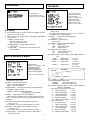
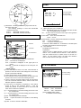
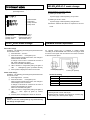
HD-SDeye
Full HD HD-SDI Camera
KP-HD20A
Operation manual
Thank you for procuring this fine Hitachi Kokusai Electric color camera.
Before using the camera, please read this operation manual carefully and
keep this manual on file for ready reference in the future.
Hitachi Kokusai Electric Inc.
E400359115
Contents
Caution for safe operation
Contents
Introduction
Features
······························· 1
···································· 1
Standard Composition ·················· 1
Name and function························ 2
Connections·································· 3
Lens·············································· 4-5
Setting ·········································· 6-10
Specifications································ 11
Introduction
Features
High definition
Hitachi’s camera KP-HD20A is HD-SDI interface one
which support Full HD.
・They are high definition and wide viewing angle because
it is full HD.
・Low delay HD video signal and long-distance transmission
(at the time of multiunit connection)
High sensitivity
・1/3 type high sensitivity MOS sensor has made 0.2lux
high sensitivity.
High functioning
・Full HD and double shutter WDR function
・1080/30fps double shutter WDS function.
Coaxial superposition
・A simple system configuration is possible by one cable
connection.
Standard composition
1) Camera
2) Operation manual
3) Tripod adapter
4) Attchement screw x 3
1
Name and function
Attachment of C mount adapter
Attachment of tripod adapter
LENS mount ring
Tripode adaptor installation screw hole
C mount adapter
(optional accessories)
LENS connector [LENS]
Connect the lens cable,
when using automatic iris
lens. Refer to page 4 (Lens
connectors).
Lens mount fixing screw
Adjust the flange back
Refer to page 4 (Flange back
adjustment)
Camera attachment screw hole
Tripod adapter
Back
Status lamp [STATUS]
Camera state is indicated
・HD-SDI output mode:Turn green light
・VIDEO output mode :Flicked green
light
Camera menu setting operation switch [MENU]
Various setting and adjustment values are
confirmed and changed with these 3 switches.
Refer to page 6 to 10 (Setting menu operations).
Power supply input connector
Refer to page 3 (Video output
connection).
HD-SDI output connector [SDI]
Refer to page 3 (Video output
connection).
REMOTE connector [REMOTE]
Refer to page 10 (Remote-contact).
Video output connector [VIDEO]
Refer to page 3 (Video output
connection).
2
Connections
Example of connection
RGB monitor
Supported formats
XGA 60p
SXGA 60p
RGB cable
AC100~230V
HD-SDI output
HD-VLC output
HD-SDeye color camera
KP-HD20A
MU-HD101 back
Coaxial cable
Refer to cable length
standard
DC12V
or
Coaxial superposition
DVI-D cable
Coaxial cable
DVI – D
moronit
Coaxial cable
HD-SDI output
HD-VLC output
Analog video output for
field angle adjustment
NTSC/PAL
monitor
Supported formats
1080 59.94i
1080 50i
1080 29.97p
1080 25p
XGA
60p
SXGA 60p
Cable length standard
5C-FB ( No power supply
supperposition)
HD-SDI mode(1.5Gbps)
HD-VLC mode (270Mbps)
100m
300m
* Actual distance changes with cable, connector, temperature, etc, because transmission distance is actual measurement
by sample cables.
* We recommend using cable of 7C-FB or 5C-FB at the time of using HD-SDI mode, because 7C-2V, 5C-2V and 3C-2V
are not guaranteed to support high-frequency signal transmission of HD-SDI mode.
3
Lens
Lens selection
Lens connectors
1) Dimension A) of lens installation part should be according to
the figure below. When the lens with dimention more than the
following size is installed, the internal damage of camera may
occur.
2) Please do not install a lens which is heavier than the camera
body. In case of using such lens, please fix the lens to the
installation stand.
When a lens-connector-free automatic iris lens is used, the
optional lens plug is installed in the lens cable as follows.
Please refer the manual for signal and color combination of
camera cable.
DC(Direct current)control voltage input type lens
Damping coil
-
Damping coil
+
Driving coil +
Caution
Use of heavy lens may damage the camera because of
unbalance.
Driving coil -
A
Video signal input type lens
+12V
Video input
C mount lens:less than 4.1mm
CS mount lens:less than 4.1mm
Lens
GND
Flange surface of lens
Install the head of lens cable to plug and then insert the plug in
the lens connector [LENS] of camera.
Flange back adjustment
Flange back adjustment is needed after installation of lens or in
cases where focus cannot be obtained by normal lens focus
operation and focus is lost at the wide angle settings of a zoom
lens.
In such cases, open the lens iris (refer to page 9) and adjust as
follows.
※ The flange back adjustment can adjust C~CS mount range.
※ The angle of view is adjusted by turning the lens zoom ring.
1) Fixed focus lens
Set the lens focus ring to infinity and pickup a camera subject
at least 20 meters distant. Loosen the lens mount setscrews
(2 screws) and turn the lens and lens mount ring to adjust the
focus. After adjusting, tighten the lens mount setscrews.
2) Varifocal and Zoom lens
1) Set the lens to maximum telephoto and pickup a camera
subject at least 20 meters distant. Loosen the lens mount
setscrews (2 screws) and turn the focus ring to adjust the
focus while using care not to turn the lens and lens mount
ring.
2) Set the lens to maximum wide angle and pickup the same
camera subject. While using care not to turn the lens focus
ring, turn the lens and lens mount ring to adjust the focus.
Repeat these steps until focus is obtained at both telephoto
and wide angle settings. After adjusting, tighten the lens
mount setscrews.
Note
KP-HD20A camera has strucuture that user can change lenses.
Therefore dust may adhere to the CCD or the optical filter unit
depending on environmental conditions where lens are attached
to this camera. If you use this camera under the bright outdoor
conditions, dust may be seen depending on the aperture of lens
In such cases we recommend that you use AES & LENS mode.
4
Note
If an auto iris lens is used and the object distance is less
than few meters, due to focus length of lens, slight blurring
can occur at certain iris positions.
In such case, please refer to page 9[Lens open setting]
and set the lens to full open. At this time, AES is operated.
Auto Electric Shutter (AES)
AES is a function to automatically adjust the electronic
shutter speed according to the amount of incident light
and keeps the image level constant.
5
Setting
Setup by the operating switch in a back part
Up(U)
Down(D)
Right(R)
Left(L) button: Movement of a cursor
Center (Set) button: Determination of a selection item
MENU buttons
Composition of camera setting menu
MAIN MENU
[FILE1 ]
LIGHT CONT. MENU
SHUTTER
:1/30
PEAK/AVE. :0/100
LEVEL
: 0
ALC GATE :OFF
LIGHT CONT. :->
GAIN
:->
WHITE BAL. :->
SUB
:->
TITLE
:->
LENS
SYSTEM
:->
:->
SYSTEM MENU
SDI OUTPUT :HD-SDI
TV FORMAT :1080p,59.94
VBS ASPECT :16:9
WDR
*WDR
*WDR
*WDR
GAIN MENU
GAIN MODE :AGC
*PRESET GAIN: 0dB
AGC LIMIT : 31dB
MODE :AUTO
BLEND :128
SHUTTER:1/2000
LEVEL : 0
WHITE BAL. MENU
KNEE
MODE
:ATW
ATW RANGE :NORMAL
SLOPE1
SLOPE2
POINT1
POINT2
*AWB
*R GAIN
*B GAIN
:PUSH R
: 0
: 0
:
:
:
:
72
24
48
80
WHITE GATE :OFF
TV FORMAT
1080i,59.94Hz
* 1080i,50 Hz
1080p,29.97Hz
* 1080p,25 Hz
SUB MENU
CHROMA
DETAIL
PEDESTAL
GAMMA
KNEE
KNEE S/P
MASKING
*HUE/SAT
MASKING
: 0
: 0
: 0
:ON
:ON
:->
:PREST
:->
INITIALIZE :PUSH R
TITLE
(HUE)
R: 150
Y: 128
G: 172
C: 150
B: 120
M: 160
(SAT)
R: 128
Y: 128
G: 128
C: 128
B: 128
M: 128
INITIALIZE :PUSH R
LENS MENU
MODE
TITLE
:OFF
:
Indication is factory
shipment setting.
LENS TYPE :DC
IRIS GAIN : 0
LENS OPEN :OFF
L
6
H
MAIN MENU
LIGHT CONT MENU
1) Press the Set button for at least 2 seconds to display the
Main menu on the monitor screen.
……Seting scene files setting
……Exposure control mode
……Video level adjustment
……Automatic level conrol gate setting
……Shutter speed setting
……Light control menu
……AGC setting menu
……White balance setting menu
……Sub menu
……Camera title setting menu
……WDR function setting
……WDR brend ratio setting
……WDR short exposure shutter setting
……WDR short exposure convergence
level setting
……Lens setting menu
……Camera tilte setting menu
Light control menu
Main menu
2) Check the current settings at the main menu.
3) Shift the cursor vertically by pushing the Up and Down
buttons, then press the Set button to change the setting of
the selected item.
4) To return to the normal screen, press the Set button.
5) Changed settings are stored in the camera memory (flash
memory) and restore them when the power is switched on.
6) When button operation is not performed for 1 minute during
displaying menu, changed items are saved and menu display
disappears.
Scene file setting
Scene file is a function to record various mode settings and the
adjusted values of the camera at the file.
1) Press the Set button for at least 2 seconds to display the
main menu on the monitor screen.
2) Use UP and Down buttons to move the cursor to MAIN
MENU. push the Right and Left button to change the scene
file.
FILE1<->FILE2<-> FILE3<->FILE4<->FILE5<->FILE1
Factory setting is FILE1.
SHUTTER SPEED
1) Shutter speed can be switched at MAIN MENU. Select
"SHUTTER" by Up (Down) button. Then shutter speed can
be changed by Right/Left button.
[Preset]
1/30(1/25) →1/50 →1/100 →1/250 → 1/500 → 1/1000
→1/2000→1/5000→1/10000→1/20000 →1/50000
→AES→AES&LENS(1/1000)→AES&LENS(1/2000)
→AES&LENS(1/5000)
Factory setting is “1/30”.
* AES&LENS is AES priority mode.
7
Light control menu setting
1) Press the Set button for longer than 2 seconds to display
the Main menu.
Select “LIGHT CONTROL” by Up (Down) button. Then LIGHT
CONTROL MENU can be displayed by Rght,
(1) PEAK/AVE:(PEAK/AVERAGE)
Set the rate of automatic iris PEAK/AVERAGE.
0/100, 15/85, 30/70, 50/50, 75/25, 100/0.
(2)LEVEL:(LEVEL)
Standard level of Automatic exdposure control( AUTO IRIS,
AGC, AES ) (dark)-128 to 0 to127(bright)
(3)ALC GATE:(PEAK/AVERAGE)
Set PEAK/AVERAGE Automatic level control gate.
OFF:Full screen、 Select 1 to 9.
(4) WDR MODE:(Wide dynamic range mode)
Set WDR.
OFF/ON(manual)/AUTO
(5) WDR BLEND:(WDR short/long exposure ratio)
Set WDR short/long exposure ratio.
128(50%)to 255(100%)
Effective only at the time of WDR ON
(6) WDR SHUTTTER:(WDR short exposure shutter speed)
Set the shutter speed of short exposure at the time of WDR
manual mode. Long exposure is set by SHUTTER
command.
(7) WDR LEVEL:(Short exposure shutter desired value of
AUTO)
Short exposure convergence level setting of short exposure
shutter automatic control
0(95%)to 255(110%)
Effective only at the time of WDR Auto mode
GAIN MENU
SUB MENU
……Chroma level setting
……Detail correction setting
……Black level setting
……Gamma correction setting
……KNEE mode setting
……KNEE function setting
……Masking mode setting
……Masking function setting
……Gain mode setting
…… Fixed amplification setting
…… Maximum amplification setting
Gain setting
1) Press the Set button for at least 2 seconds to display the main
menu on the monitor screen.
2) Select GAIN by Up (Down) button, and display GAIN MENU
by Right button.
(1)MODE:Set gain mode.
PRESET:Preset gain mode
AGC:Automatic gain mode
(2)PRESET GAIN:Set gain value of manual.
0dB to 48dB
(3) AGC LIMIT: Set maximum of the automatic gain.
0dB to 48dB B
WHITE BALANCE MENU
……Mode setting
……Range of Following color
temperature setting
……One push setting
……Manual setting(R gain)
……Manual setting (B gain)
(1) CHROMA:Chroma level setting
-128 to 0 to 50
Choroma level is fixed to the value of “-128”, and cannot
be adjusted, at time of B/W MODE.
(2) DETAIL: The optimum detail levelseting
-128 to 0 to 127
(3) PEDESTAL:Set black level.
-28 to 0 to100
(4) GAMMA:Gamma correction setting
ON
: Gamma ON
HIGH : Gamma ON (High)
OFF
: Gamma OFF
(5) KNEE MODE: Mode select
OFF : Not use KNEE function
ON
: Use Knee fnction
(6) KNEE: KNEE function setting when KNEE MODE is
“ON”.
SLOPE 1 : KNEE slope 1
0 to 255
SLOPE 2 : KNEE slope 2
0 to 255
POINT 1
: KNEE point 1
0 to 255
(64 = 100%)
POINT 2
: KNEE point 1
0 to 255
(64 = 100%)
SLOPE 1
SLOPE 2
……Auto level conrol gate setting
POINT 1
White balance setting menu
POINT 2
(7) MASKING MODE: Mode select
PRESET
: Use a standard preset
VARIABLE
: Use a user setting mode
(8) MASKING: Masking function setting when MASKING
MODE is “VARIABLE”.
(SAT): Degree of saturation of the color
R : Red mask setting
1 to 255
Y : Yellow mask setting
1 to 255
G : Green mask setting
1 to 255
C : Cyan mask setting
1 to 255
B : Blue mask setting
1 to 255
M : Magenta mask setting 1 to 255
(HUE): Color phase
R : Red mask setting
0 to 255
Y : Yellow mask setting
0 to 255
G : Green mask setting
0 to 255
C : Cyan mask setting
0 to 255
B : Blue mask setting
0 to 255
M : Magenta mask setting 0 to 255
(1) MODE:Set white balance mode
ATW:Automatic whilte balance.
Manual:Set white balance.
(2) ATW RANGE: Set Range of Following color temperature
NORMAL:2500K to 8000K.
SPECIAL:2500K to 8000K+special light
(Sodium lamp、mercury lamp)
(3) AWB: One push automatic white balance
A white balance is adjusted with auto after pressing the right
button. The value of R and G GAIN is updated and it fixes to
MANUAL.
(4) R GAIN:White balance hand regulation of R gain
-128 to 0 to 127
This operates, only when a white balance is a manual.
(5) B GAIN:White balance hand regulation of B gain
-128 to 0 to 127
This operates, only when a white balance is a manual.
(6) WHITE GATE: Set auto level control of white balance.
OFF/ NO.1 to NO.9
8
LENS
R
M
LENS
Y
(SAT)
(HUE)
G
……Lens type setting
……Iris gain setting
……Lens open setting
LENS TYPE :DC
IRIS GAIN :
0
LENS OPEN :OFF
B
C
L
(7) INITALIZE:Initializing in the factory-shipments state for
the current scene file.
The following message is show after INITIALIZE
command execution.
Push R: INITIALIZE command cancel
Push D: INITIALIZE command execution
H
(1) LENS TYPE:DC type or VIDEO type
VIDEO : B/W MODE AUTO does not operate at the time of AGC
OFF and SENSUP OFF / manual..
DC : To which control of the lens of DC input control (position
servo) is attained.
(2) IRIS GAIN: Set a control standard level
-128 to 0 to127
(3)LENS OPEN:A lens is opened wide and AES is turned ON.
OFF : Control automatic iris
ON : Lens open and AES control.
At the time of ENS OPEN ON, * is attached to a shutter speed
command and operation becomes improper.
(4) Level indicator
The NAM level meter for ALC
- Explanation When the value of NAM detection is equal to the reference
level of ALC, a marker moves to central "+" mark. When it is
less than reference level, a marker moves on the left of a
center. On the contrary, when it is larger than reference
level, a marker moves on the right of a center.
TITLE
Set data
Character
For edit control
MODE : Set the display position of a camera title
OFF: A character is not displayed.
TOP:A character is displayed on the upper part of a
screen.
.BOTTOM:A character is displayed on the lower part of a
screen.
<TITLE setting>
(1) In the state where a cursor is in TITLE, if the Set button is
pushed, a cursor will move to the setting line of TITLE data,
and the 1st character will blink.。
(2) Select the characters by four directions button.
(3) The character chosen is inputted when the Set button was
pushed. This cursor moves to the following character.
(4) Once it goes into character setting mode The Set button
turn into a character selection button, and the usual menu
ON/OFF operation is forbidden.
(5) If the input of a character is completed, a cursor will be
moved to RET by four directions buttons. If the Set
buttons are pushed, a cursor will move to TITLE and will
return to the usual menu operation.
(6) <-: Character blink of a character setting part moves to the
one character left.
(7) ->: Character blink of a character setting part moves to the
one character left.
(8) DEL : The blinking character eliminate.
(9) INS : A space is inserted in the position of the blinking
character.
(10) RET : A cursor is moved to DATA SET.
SYSTEM MENU
……SDI output setting
……TV format setting
(1) SDI OUTPUT :Set transmission mode
HD-SDI: 100m transmission
HD-VLC: 300m transmission
(2) TV FORMAT (video output)
TV FORMAT function setting.
9
HD-SDI/HD-VLC mode change
TV FORMAT MENU
Operation:Select TV FORMAT by Up (Down) button, and
press Right button.
Button operation at a camera start-up
(1) Starting in HD-SDI mode
A power supply is started pushing an Up button.
(2) Starting in HD-VLC mode
……1080i 59.94Hz
……1080i 50Hz
……1080p 29.97Hz
……1080p 25Hz
A power supply is started pushing a Right button.
※Exclusive multiunit MU-HD101 is required for HD-VLC
mode.
(1) 1080i 59.94Hz
(2) 1080i 50Hz
(3)1080p 29.97Hz
(4)1080p 25Hz
(NTSC MODE ONLY)
(PAL MODE ONLY)
(NTSC MODE ONLY)
(PAL MODE ONLY)
Remote-contact operation
NTSC/PAL mode change
PAL mode change
Operation:The following processings are performed at the
time of NTSC mode .
① Push left button.(5 times)
LED lights up red.
② Push Down button.
When it pushes except Down button, the change to
NTSC mode is canceled.
A change in PAL mode is canceled at the time of
PAL mode (LED lights up green).
When it is canceled, LED blinks green.
③ LED is turned on orange after putting out lights of
LED. → LED lights up green. (a camera reboots)
④ A PAL picture is displayed in about ten seconds.
An optional remote plug is available to enable remote
controlling of the B/W MODE and scene file. The plug is wired
as shown in the figure and connected to the remote connector
of the camera rear panel.
Remote plug (option)
NTSC mode change
Operation:The following processings are performed at the
time of PAL mode.
① Push Right button.(5 times)
② Push Down button.
LED lights up red.
When it pushes except Down button, the change to
NTSC display mode is canceled.
A change in PALmode is canceled at the time of
NTSC mode (LED lights up green).
When it is canceled, LED green.
③ LED is turned on orange after putting out lights of
LED. → LED lights up green. (a camera
reboots)
④ A NTSC picture is displayed in about ten seconds
D-sub 9 pin (female)
Scene file setting
Pin No.
Signal name
1
N.C.
2
Serial data camera input
3
Serial data camera output
4
GND
Note
1) Nothing should connect with NC pin.
2) Please perform extraction and insertion of a remote plug
after turning off a camera power supply.
Caution!
Please do not turn off the power by any means during
the change of output mode.
10
Specifications
1)
2)
3)
4)
5)
6)
7)
8)
9)
10)
11)
12)
13)
14)
15)
16)
17)
18)
19)
20)
21)
22)
Imaging device
Total pixels
Effective pixels
Sync system
Video output
Video format
1/3” Progressive Scan MOS
2010(H)x1108(V) 2.2M pixels
1944(H)x1092(V) 2.1M pixels
Internal
HD-SDI / Analog CVBS
HD-SDI: 1080i 59.94/ 50, 1080P 29.97/ 25
CVBS: NTSC/ PAL
Transmission distance
HD-SDI Std mode: max100m (5C-FB 75ohm)
HD-VLC mode: max 300m (5C-2V 75ohm/ Exclusive multiunit MU-HD101 use)
*mode selectable
Minimum illumination
Color: 0.2lx(F1.2/AGC48dB)
S/N ratio
50dB(AGC: OFF/Weight: ON)
Resolution
800TV line
Lens mount
C/ CS *C: C mount Adaptor (optional accessory) use
Power consumption
DC12V or Coaxial superposition from MU-HD101 5.8W
Operating temperature
-10 to +45 C
External dimensions
44(W)x44(H)x59(D)mm
Mass
Approx.130g
Accessory (optional accessory) Lens/Lens plug/Tripod adapter/Power plug/Remote plug/Multiunit (MU-HD101)
AGC
OFF/ Auto (Max Gain 48dB)/ Manual (0dB to +48dB)
*1dB step setting
Electronic shutter
OFF/ AES/ Manual (1/30(1/25) to 1/50000 sec)
BLC
OFF/ ON (photometry aria can be set)
White Balance
Auto: ATW/ AWC Manual: Manual (2500K to 10000K)
Wide dynamic range
OFF/ON/AUTO
*WDR: Double shutter sampling
Picture adjust menu
Video level/Gamma correction/Chroma level/Black level/Enhance level
Lens control
DC/VIDEO
Remote control
RS-232C
6
12