1
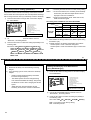
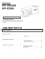
CCD Camera
KP-DE500
KP-E500
This manual is applied to the product since “R1".
Operation manual
Before using the camera, please read this operation manual
carefully and keep this manual on file for ready reference in
the future.
Hitachi Kokusai Electric Inc.
Table of contents
CAUTION FOR SAFE OPERATION…………...
IMPORTANT NOTICE…………………………...
General…………………………………………….
Features…………………………………………..
Operating considerations……………………...
Phenomena inherent to CCD image device...
Section names and functions…………………
Connections……………………………………...
Lens………………………………………………...
Recommended lenses…………………………
Note on lens selection………………………….
Installation of CS-mount lens………………….
Lens selector switch……………………………
Flange back adjustment……………………….
Camera mounting………………………………..
A
J
1
1
2
3
4
6
7
7
8
8
9
10
11
Setting menu description……………………..
Setting menu composition……………………
Menu operations……………………………….
Main Menu……………………………………...
Camera Title Menu…………………………….
Light Control Menu…………………………….
AGC setting…………………………………….
Shutter Speed setting…...…………………….
Sensitivity enhance setting…………………...
Raising sensitivity by color-B/W selection…..
White Balance Menu...………………………..
Sub Menu………………………………………
Remote menu operation……………………….
Specifications……………………………………
Accessories……………………………………...
Supplied accessories………………………….
Optional accessories………………………….
12
12
13
13
14
16
19
22
23
24
26
30
33
34
35
35
35
General
The KP-DE500 is an ultra high sensitivity color camera
that utilizes the electron multiplication type CCD
(EM-CCD) image sensor.
The KP-E500 is an ultra high sensitivity camera that
utilizes the electron multiplication type CCD (EM-CCD)
image sensor.
Features
Ultra high sensitivity
Ultra high sensitivity is possible due to the electron
multiplication (EM) CCD which multiplies the charge on
the individual pixels before the charge is converted to a
voltage, eliminating noise that would be associated with
amplification gain. Moving images retain the clarity and
sharpness even under low light conditions.
High color fidelity
An RGB primary color mosaic filter is used to produce
images of high vertical resolution and color fidelity.
New digital signal processor (DSP)
A new Digital Signal Processor (DSP) with improved
luminance signal processing and a 5 H enhancer is used
to obtain high quality images with a high signal to noise
(S/N) ratio.
Various functions
・Auto tracking white balance (ATW)
・Color / Black & White select
・Digital noise reduction (DNR)
・Electric shutter speed
・Electric sensitivity enhance
・Backlight compensation (BLC)
・Text display (character generator)
1
Operating considerations
Power supply
Be sure to use the power source specified in the Major
Specifications.
・Before plugging or unplugging a connector, be sure
to turn off power.
To plug or unplug a connector, be sure to hold the
connector section.
・Note that it will take several seconds until a picture is
displayed on the monitor after power on.
Handling
・Do not attempt to remove cover.
・When installing or removing a lens, be sure to use
care that water or dust does not enter the inside of.
the camera.
Installing and storage
Avoid installing or storing the camera in the following
environments.
・Environments exposed to direct sunlight, rain or snow
・Environments where combustible or corrosive gas
exists
・Excessively warm or cold environment (Operating
ambient temperature: -10 to 50℃)
・Humid or dusty environment
・Place subjected to excessive vibration or shock
・Environment exposed to strong electric or magnetic field
2
・Do not aim the camera lens at the sun.
・Do not shoot strong light or a scene including strong light.
When such a scene is shot, vertical trailings will appear.
However, this is not due to failure.
In case strong Tight enters the camera through the lens,
partial deterioration in picture quality will result.
To obtain stable performance for long time
When the camera is used continuously for long time
under high ambient temperature, the inside electrical
parts become deteriorated, resulting in shortening its life.
To use the camera continuously for long time, the
highest temperature must be below 40℃.
Cleaning
・Use a blower or a lens brush to remove dusts on the
lens or the optical filter.
・Wipe dirts on the case off with dry soft cloth. lf dirks
are hardened, wipe them off with cloth moistened
with neutral detergent liquid; wipe the cover with dry cloth.
・Do not use benzine,thinner,alcohol,liquid cleaner or
spray-type cleaner.
・In event dust or other debris is lodged between the CCD
and optical filter, consult dealer for cleaning by an optical
technician.
Phenomena inherent to CCD imaging device
Following are the phenomena inherent to a CCD imaging device, and not defects
1) Smear and blooming
When strong light (lamp, fluorescent lamp, and
reflected light, etc.) is shot, a blue belt to remain thinly
in vertical and the horizontal direction of light might go
out.
2) Fixed pattern noise
When the camera is operated in a high temperature,
fixed pattern noise may appear on the entire screen.
3) Moire
When fine patterns are shot, moire may be displayed.
4) Burning
Moreover, the lower side on the monitor screen might
become pure-white momentarily.
When excessively intense light comes to the CCD for a
long time, the spectral filter in the CCD pixel may be
deteriorated, and the color of the corresponding portion
may change.
Avoid using the camera under such condition.
In this case, change the angle of the camera so that
such strong light does not enter the camera through
the lens.
3
Section names and functions
Tripod adaptor holes
See camera mounting
on page 11.
Lens mount screws
See page 10.
Lens mount ring
See flange back adjustment
on page 8.
Lens connector[LENS]
Connect lens cable when
using an auto iris lens. See
page 9.
C-mount adaptor
See installation of CS-mount
lens on page 8.
Camera mounting hole
See page 11.
4
Set up buttons[SETUP]
Use when setting up and adjusting
the camera with reference to the
screen menu. See page 13.
Remote connector
[REMOTE]
Use for remote menu
operations.See page 32.
Lens select switch[LENS]
Set according to the type of
lens. See page 9.
Video output connector[VIDEO]
See connections on page 6.
DC input connector
See page 6.
5
Connections
Video output connection
External power supply connection
Connect the video output of the camera to the video input of a
monitor or other equipment. When using a “loop through”
connection of two or the more monitors, set the 75Ω switch of
only the final monitor to ON.
Determine the type of cable according to the distance of the
connected equipment. The maximum cable lengths indicated
below are recommended for avoiding appreciable picture
degradation.
3C-2V
・・・・ 150m
5C-2V
・・・・ 200m
7C-2V
・・・・ 300m
10C-2V
・・・・ 400m
Use a stabilized 12 VDC(±10%) power supply rated at 2.5
ampere or greater. Wire the accessory 3-pin DC plug as
shown in the figure for connecting the power supply to the
camera.
Caution
Be sure to confirm proper polarity before switching
on power.
DC input connector
KP-DE500
KP-E500
Monitor 1
Monitor 2
Monitor 3
75-ohm coaxial cable
Set the 75Ω switch of only the final monitor to on.
Set the 75Ω switch of other monitors to off.
6
Lens
Recommended lenses
Use an auto iris lens having a plug pin arrangement conforming to EIAJ (Electronic Industries Association of Japan)
specifications.
This camera is using a CCD that has sensitivity in infrared region ( from 700 to 1000nm ).
Please select a lens for use from the following recommendation lens table.
Type
Auto iris
Lens model
1/2
1 2 V G 4 1 2 AS I R
1 2 V G 1 0 4 0 AS I R
D V 5 × 3 . 6 R 4 B - S A2
HG3Z4512FCS-IR
Specification
4.0∼12.0
10.0∼40.0
3.6∼18.0
4.5∼12.5
mm
mm
mm
mm
F1.2∼360
F1.4∼360
F1.8∼360
F1.2∼360
Lens mount
C-mount
C-mount
CS-mount
CS-mount
Lens switch
DC
NOTE
If another type of lens is used, it may detract from camera performance or there may be difficulty is attaching the lens.
When procuring, be sure to specify the EIAJ compatible plug.
7
Installation of CS-mount lens
Note on lens selection
1)
2)
Observe the maximum size limit (A in the figure)
When installing the lens. Internal damage can occur
If a larger lens is used.
C-mount adaptor is provided for the camera in the factory.
When using a CS-mount lens, unscrew and remove the
C-mount adaptor. Save the C-mount adaptor for possible future.
Avoid using a lens that is heavier than the camera.
If unavoidable, be sure to fix the lens itself on a support.
Caution
A heavy lens can disturb the balance with respect to
The camera and possibly result in damage.
A
C-mount lens: Less than 4.1mm
CS-mount lens: Less than 4.1mm
Lens
Lens flange surface
8
Lens selector switch
Set the switch according to the type of auto-iris lens.
The factory setting is DC.
Lens connector
When using an auto iris lens, install the lens plug on the lens
Cable as indicated in the figures. Refer to the lens instructions
Regarding the signals and wire colors.
DC type lens
DC
:Set to DC when using a lens having a DC
Control voltage input.
VIDEO
:Set to VIDEO when using a lens having a
Video signal input.
Damping coil
−
Damping coil
+
Drive coil
+
Drive coil
−
Video type lens
NOTE
1) To the extent possible, set the lens response to
Average. Hunting can occur toward the Peak setting.
2)
+12V Video input
When adjusting the level, choose a location with
adequate brightness (more than 300 lux) where the
AGC and Sens Up functions are not needed.
GND
After installing the plug on the cable, connect it to the lens
connector on the rear of the camera.
9
Flangeback adjustment
Flangeback adjustment is needed in cases where focus cannot
be obtained by normal lens focus operation or focus is lost at the
maximum telephoto and wide angle settings of a zoom lens.
In such cases, open the lens iris and adjust as follows.
Zoom lens
1)
2) Turn the lens focus ring to adjust the focus.
3)
Set the lens to wide angle. Loosen the (2) lens mount
screws and turn the lens mount ring to adjust the focus.
Use care not to disturb the lens focus ring.
4)
Again set to telephoto but adjust the focus by turning the
Lens focus ring.
Fixed focus lens
1) Set the lens focus ring to infinity.
2)
Aim toward an object at least 20 meters distant.
3) Loosen the (2) lens mount screws and turn the lens mount
ring to adjust the focus. Use care not to disturb the lens
focus ring.
4) Tighten the lens mount screws.
NOTE
If using an auto iris lens and the adjustment object distance
is less than several meters, due to lens depth of focus
relationship, slight blurring can occur at certain iris positions.
In this event, darken the scene so as to open the iris and
adjust the focus or flangeback to prevent the blurring.
10
Set the lens to telephoto and aim toward an object at least
20 meters distant.
5) Repeat these steps and carefully adjust for best focus.
6) Finally, tighten the lens mount screws.
Camera mounting
If the camera is to be suspended from the ceiling,
change the position of the tripod adaptor from the
bottom to the top of the camera, as indicated in the figure.
Caution:
Tripod adaptor
Use the following type of camera mounting screw.
Type :U 1/4-20
Length:L=7mm
Binding head screws M3 x 8
If longer than 7 mm, there is risk of internal damage to
the camera. Conversely, if too short, the camera will not
be firmly secured and there is risk of dropping.
11
Setting menu description
The camera setting and adjustments can be changed to conform to conditions of use. Use the setting menu indicated on the monitor
screen to check and change the settings and adjustments. The setting menu is comprised as follows.
Setting menu composition
Main Menu
(page 13 )
Camera Title Menu (page 14 )
Light Control Menu (page 16 )
AGC Menu (page 19 )
・Display character setting
・Display position setting
・Light control mode setting
・Video level adjustment, etc.
・AGC mode setting
・Fixed and limit gain setting
Shutter Speed setting (page 22 )
Sensitivity enhance setting (page 23)
・WB mode setting
・WB detection area setting
・Manual R/B gain adjustments, etc
Color-B/W selection (page 24 ) (*)
White Balance Menu (page 26 ) (*)
Sub Menu (page 30 )
(*) Note: Only KP-DE500
12
・Gamma
・Chroma gain adjustment
・Black reference level adjustment
・Detail adjustment
・Polarity
・Digital noise reduction
・Burst signal
・Camera reset
Menu operations
Main Menu
Three rear panel setup buttons are used to shift the cursor and
select items from the menus.
1) Press the SET button for at least 2 seconds to display
the main menu on the monitor screen.
◆◆ MAIN MENU ◆◆
TITLE :OFF ↵
LIGHT CONTROL:OFF ↵
AGC
:ON ↵
SHUTTER SPEED:OFF
SENS UP
:OFF
B/W MODE
:OFF
WHITE BALANCE:ATW ↵
SUB MENU ↵
END
>CAMERA
①
②
……
……
……
……
……
……
……
……
……
Camera title setting menu
Light control setting menu
AGC setting menu
Shutter speed setting
Sensitivity enhance Setting
B/W mode setting (*)
White balance mode setting menu (*)
Sub menu
End of menu display
③
MAIN MENU
① Up button
: Shift the cursor in the upward direction or
increase an adjustment value.
2)
Check the present settings at the main menu.
② Down button
: Shift the cursor in the downward direction
or decrease an adjustment value.
3)
③ Set button
: Press to display the main menu or to
change a setting.
Shift the cursor vertically by pressing the UP and DOWN
buttons, then press the SET button to enable changing the
setting of the selected item.
4)
If changes are unnecessary, shift the cursor to “END” and
Press the SET button to return to the normal screen.
5)
When an item indicated by a ↵ mark is selected, pressing
the SET button shifts to the next menu.
Note:
lf no button is pressed, the menu display extinguishes
automatically after about 5 minutes.
(*) Note: KP-E500 is not displayed.
13
Display character input
Camera Title Menu
1)
One line of up to 22 alphanumeric characters can be displayed
on the screen. The display on/off and position are selected at the
camera title menu.
1)
◆ CAMERA TITLE MENU ◆
>MODE
:TOP
0123456789
ABCDEFGHIJKLM
NOPQRSTUVWXYZ
!?#&( )、 .
:;∼*%
+−x/=
Press the SET button for longer than 2 seconds to display
the main menu.
2)
Use the UP and DOWN buttons to shift the cursor to
“CAMERA TITLE”, then press the SET button to display the
camera title menu.
3)
SPACE
←
→
RESET
POSITION RET
END
CAMERA NO.1・・・・・・・・・・・
While the cursor is at “MODE”, press the SET button to shift
the mode in the sequence “OFF”, “TOP”, “BOTTOM”.
: Characters not displayed. (Factory setting)
: Characters displayed at top of screen.
: Characters displayed at bottom of screen.
OFF
TOP
BOTTOM
◆ CAMERA TITLE MENU ◆
>MODE
RET
END
:OFF
…… Display On/OFF and position
( OFF / TOP / BOTTOM )
…… Return to the main menu
…… End of menu display
CAMERA TITLE MENU (MODE: OFF)
14
When the mode is Top or Bottom, the characters indicated in
the figure can be used.
…… Display On/OFF and position
( OFF / TOP / BOTTOM )
Input character select table
…… Blank, cursor shift (left / right), character delete
…… Display position, return, end
…… Input character display
CAMERA TITLE MENU (MODE: TOP or BOTTOM)
2)
Press the DOWN button, then use the UP and DOWN
buttons to shift the flashing cursor sequentially among the
usable characters.
3)
When the SET button is pressed, the selected character is
entered in sequence beginning with the left-most of 22 dots
shown at the bottom of the screen.
Afterwards, each newly selected character is entered
sequentially toward the right.
The item under character input selecting department uses it in
the following manner.
SPACE
: To add a blank space, shift the flashing cursor to
“SPACE”, then press the SET button.
←・→
1)
: The input characters can be edited by using the
arrow symbols.
2) Press the UP and DOWN buttons to shift the characters
horizontally. Afterwards, press SET to confirm the display
position and return to the main menu.
Set the flashing cursor to either of the arrow symbols and
Press SET button. The flashing cursor shifts in the arrow
direction. Press the SET button repeatedly to where the
flashing cursor overlaps the character to be changed.
2)
UP button
CAMERA
DOWN button
…… Character position (Top)
NO.1
Select the character to be inserted with the UP and DOWN
buttons, then press SET to change the character.
RESET
: To delete all characters from the display, shift the
flashing cursor to “RESET”, then press SET. After
deleting, the flashing cursor returns to the start of
the input character select table.
RET
: Position the flashing cursor to “RET” and press SET
to exit the “CAMERA TITLE MENU” and return to
the “MAIN MENU”.
…… Character position (Bottom)
Title positioning screen (Top)
: Shift the cursor to “END” and press the SET button to
close the menu and return to the normal screen.
END
Title positioning setting POSITION
Use when the display position on the screen has been
determined.
1) Shift the flashing cursor to Position and press SET to open
the title position screen indicated in the figure. Screen top
and bottom positions are determined respectively by
“MODE” settings “TOP” and “BOTTOM”.
15
◆
Light Control Menu
LIGHT
>MODE
CONTROL
MENU
:AVERAGE
◆
…… Select light control mode
Light control mode setting
1)
Press the SET button for longer than 2 seconds to display
the main menu.
2)
Use the UP and DOWN buttons to shift the cursor to
“LIGHT CONTROL”, then press the SET button to display
the light control menu.
3)
While the cursor is at “MODE”, press the SET button to shift
the mode in the sequence “AVERAGE”, “BLC”, “PEAK/AVE”.
AVERAGE
: Responds to the average lighting over a
broad area. (Factory setting)
BLC
: Exposure is controlled only by the
luminosity level of specific area.
(Scanning area is selectable from 9 area.)
PEAK/AVE
: The peak level and the average level are
used together and exposure is controlled.
(The ratio of a peak value and average
value is changeable.)
LEVEL
:
000
RET
END
…… Video level adjust (-128∼000∼+127)
…… Return to the main menu
…… End of menu display
LIGHT CONTROL MENU (MODE: AVERAGE)
Video level adjustment
The optimum video level is set at the factory (factory setting is
“000”). If necessary, the level can be changed as foIIows.
1)
Use the UP and DOWN buttons to shift the cursor to
“LEVEL”, then press the SET button. The adjustment value
at the right of Level flashes.
2)
Change the video level by pressing the UP and DOWN
buttons. (Variable range: -128∼000∼+127)
3)
Return the factory setting(000) by simultaneously pressing
the UP and DOWN buttons for two seconds.
4)
Press the SET button to confirm the setting and the cursor
migrates to “RET”.
Note
For video level adjustment on lenses that use the video
signal type lens iris, please refer to the user's manual
of the lens.
16
NOTE
The video level adjustment for lenses that use a video
signal type lens, is adjusted using the binding screws on
the side of the lens as shown in the method below.
1)
The lens side sensitivity binding adjustment gauge is
displayed on the light control menu, when the LENS
SW on the camera back is set to [VIDEO].
◆
LIGHT
CONTROL
>MODE
MENU
◆
:AVERAGE
Setting of BLC
In the case where there is a strong light source and sunlight in
the background, the lens iris will close according to the scene
brightness, causing the desired object in the scene to appear
dark. This mode is used under such a condition.
4)
Press the SET button for longer than 2 seconds to display
the main menu.
5)
Use the UP and DOWN buttons to shift the cursor to
“LIGHT CONTROL”, then press the SET button to display
the light control menu.
6)
The following menu is displayed. Push the SET button
to select “BLC”, when the cursor is in “MODE”.
…… Select light control mode
Lev ¦¦¦¦¦¦¦¦¦¦¦¦¦¦¦¦¦¦¦¦¦¦¦¦¦¦¦¦¦¦¦¦¦¦¦¦¦¦¦¦¦¦¦¦¦¦¦・・・・・・・・・・・・・・・・・・・・・・・
Ref ¦¦¦¦¦¦¦¦¦¦¦¦¦¦¦¦¦¦¦¦¦¦¦¦¦¦¦¦¦¦¦¦¦¦¦¦¦¦¦¦¦¦¦¦¦¦・・・・・・・・・・・・・・・・・・・・・・・
LEVEL
: 000
…… Video output level gauge
…… Control reference level gauge
…… Video level adjust (-128∼000∼+127)
RET
END
…… Return to the main menu
…… End of menu display
◆
LIGHT
>MODE
AREA
LIGHT CONTROL MENU (MODE: AVERAGE)
2)
3)
Please do the sensitivity binding on the side of the
Lens so that the value of video output level gauge
[Lev] does not drop from the value of reference level
gauge [Ref].
When the value of [Lev] is adjusted to a lower value
than the value of [Ref] the repetition phenomenon
(hunting) of the lens iris may occur along automatic
gain control in the camera.
CONTROL
MENU
◆
…… Select light control mode
:BLC
↵
SELECT:NO.1
LEVEL
:
…… Go to area select menu and selected area No.
…… Video level adjust (-128∼000∼+127)
000
…… Return to the main menu
…… End of menu display
RET
END
LIGHT CONTROL MENU (MODE: BLC)
7)
Shift the cursor to “AREA SELECT” and push the SET
button to display the detection area(BLC) select menu.
17
Setting of PEAK/AVERAGE
When there is strong spot light in the background a halo may
appear and cause obstruction to a desired object in the image.
This mode is used under such a condition.
AREA(BLC)
NO.1
Detect area position
┏━━━━━━┓
┃
┃
┃
┃
┗━━━━━━┛
6
5
4
2
1
3
7
8
9
DETECTTION AREA (BLC) SELECT MENU
5)
There are 9 light detect areas selected by the UP and
DOWN buttons. Select the areas from nos. 1 to 9 that
include the subject of main interest. (Factory setting is NO.1)
UP button
DOWN button
5)
: 1→2→3→4→5→6→7→8→9
(ascending order)
: 9→8→7→6→5→4→3→2→1
(descending order)
After deciding the detection area, push the SET button to
return to the light control menu.
1)
Press the SET button for longer than 2 seconds to display
the main menu.
2)
Use the UP and DOWN buttons to shift the cursor to
“LIGHT CONTROL”, then press the SET button to display
the light control menu.
3)
The following menu is displayed, push the SET button
and change to “PEAK/AVE”, when the cursor is in “MODE”.
◆
LIGHT
MODE
>PK/AV
LEVEL
RET
END
CONTROL
MENU
:PEAK/AVE
:
:
15/
000
85
◆
…… Select light control mode
…… Select peak / average value ratio
…… Video level adjust (-128∼000∼+127)
…… Return to the main menu
…… End of menu display
LIGHT CONTROL MENU (MODE: PEAK/AVE)
18
4)
Shift the cursor to “PK/AV” and push the SET button, peak /
average ratio value changes. As the peak value is enlarged
It reacts to spot light. Factory setting is “15/85”.
Setting AGC mode
SET button
1)
Press the SET button for longer than 2 seconds to display
the “MAIN MENU”.
2)
Use the UP and DOWN buttons to shift the cursor to “AGC”,
then press the SET button to display the “AGC MENU”.
: 15/ 85→30/ 70→50/ 50→75/ 25→100/ 0
NOTE
As the peak value increases the hunting phenomenon
of the lens reacting to the video level may cause
flickering resulting in changes of brightness in the
image.
AGC Menu
◆
AGC
>MODE
AGC
MENU
◆
:ON
LIMIT
:255
…… Select AGC mode
…… Limit gain (155∼255)
…… Return to the main menu
…… End of menu display
RET
END
AGC MENU (MODE: ON)
3)
While the cursor is at “MODE”, press the SET button to shift
the mode in the sequence “ON”, “OFF”.
ON
: The video output level is controlled automatically to a
proper value within the range of “AGC LIMIT”
according to brightness. (Factory setting)
OFF : “FIX. GAIN” mode that does not change, according
to light level.
19
Setting AGC LIMIT (AGC ON)
1)
Use the UP and DOWN buttons to shift the cursor to
“AGC LIMIT”, then press the SET button. The adjustment
value at the right of value flashes.
2)
Change the “AGC LIMIT” by pressing the UP and DOWN
buttons. (Variable range: 155∼255)
3)
Return to the factory setting(255) by simultaneously pressing
the UP and DOWN buttons for two seconds.
4)
Press the SET button to confirm the setting and the cursor
shifts to “RET”.
Setting FIX. GAIN (AGC OFF)
◆
AGC
MODE
>FIX.
MENU
◆
:OFF
GAIN
:000
RET
END
…… Select AGC mode
…… Fix. Gain (000∼255)
…… Return to the main menu
…… End of menu display
AGC MENU (MODE: OFF)
1)
Use the UP and DOWN buttons to shift the cursor to
“FIX. GAIN”, then press the SET button. The adjustment
value at the right of value flashes.
20
2)
Change the “FIX. GAIN” by pressing the UP and DOWN
buttons. (Variable range: 000∼255)
3)
Return to the factory setting(000) by simultaneously pressing
the UP and DOWN buttons for two seconds.
4)
Press the SET button to confirm the setting and the cursor
shifts to “RET”.
NOTE
1) Please note that the limitation is provided as a
function to show in next page when the amplification
level is set to 251 or more.
2) The noise in the image may be conspicuous when
high levels of amplification are used.
Notes when AGC gain is set
Please note that there is a limitation in operation of using together with the function to show in the following when the amplification level
is set to 251 or more.
1) Shutter speed setting
FIX. GAIN
AGC LIMIT
OFF
○
○
250 or less
251 or more
SHUTTER SPEED setting
1/100
From 1/125 to 1/2000
○
○
○
×(→OFF)
AES
○
○
○: possible, ×: not possible
When 251 or more sets the amplification level, the shutter speed can set only turning OFF, 1/100, and AES.
Please use by 250 or less by 1/125 – 1/2000 the shutter speed setting the amplification level to use it.
2) SENS UP setting
FIX. GAIN
AGC LIMIT
OFF
○
○
250 or less
251 or more
SENS UPsetting
AUTO
MANUAL
○
○
×(→OFF)
×(→OFF)
○: possible, ×: not possible
When 251 or more sets the amplification level, the SENS UP cannot be set. It becomes turning off fixation.
Please use by 250 or less by AUTO, MANUAL the SENS UP setting the amplification level to use it.
21
Auto electronic shutter (AES)
Shutter Speed setting
This function adjusts the light amount using only the CCD
shutter. Use this function with a fixed iris lens.
1)
Press the SET button for longer than 2 seconds to display
the “MAIN MENU”.
2)
Use the UP and DOWN buttons to shift the cursor to
“SHUTTER SPEED” ; the shutter speed setting flashes.
NOTE
1) lf using a DC type lens, fix the iris at fully open.
3)
Press the SET button to select the speed sequentially in the
following order.
2)
SET button:
OFF(1/60)→1/100→1/250→1/500→1/1000→1/2000→AES
3)
The factory setting is OFF (1/60 second).
◆◆ MAIN MENU ◆◆
TITLE :OFF ↵
LIGHT CONTROL:OFF ↵
AGC
:ON ↵
SHUTTER SPEED:OFF
SENS UP
:OFF
B/W MODE
:OFF
WHITE BALANCE:ATW ↵
SUB MENU ↵
END
>CAMERA
……
……
……
……
……
……
……
……
……
Camera title setting menu
Light control setting menu
AGC setting menu
Shutter speed setting
Sensitivity enhance Setting
B/W mode setting (*)
White balance mode setting menu (*)
Sub menu
End of menu display
(*) Note: KP-E500 is not displayed.
MAIN MENU
22
The AES function cannot be set with a video signal
type lens.
In the following types of cases, use a different shutter
speed. Strong light enters the scene, such as from a
spotlight or window.
・Strong smear or blooming occurs in the scene.
・Screen flicker or coloration occurs.
Sensitivity enhance setting (SENS UP)
The present camera includes a sensitivity enhancement function
that increases the CCD exposure time and interpolates the image
with an image stored in memory to effectively boost the sensitivity.
1)
Press the SET button for longer than 2 seconds to display
the “MAIN MENU”.
OFF
: Sensitivity enhance function not used; factory setting.
AUTO
: As the scene darkens, the sensitivity is automatically
enhanced by the selected multiple. Best mode for
day/night continuous surveillance.
MANU
: Mode for fixed sensitivity boost. When AGC is ON,
fixed at maximum gain.
The setting state of SENS UP and SHUTTER SPEED
◆◆ MAIN MENU ◆◆
TITLE :OFF ↵
LIGHT CONTROL:OFF ↵
AGC
:ON ↵
SHUTTER SPEED:OFF
SENS UP
:OFF
B/W MODE
:OFF
WHITE BALANCE:ATW ↵
SUB MENU ↵
END
>CAMERA
……
……
……
……
……
……
……
……
……
SENS UP setting
Camera title setting menu
Light control setting menu
AGC setting menu
Shutter speed setting
Sensitivity enhance Setting
B/W mode setting (*)
White balance mode setting menu (*)
Sub menu
End of menu display
OFF
SHUTTER
SPEED
(*) Note: KP-E500 is not displayed.
MAIN MENU
AUTO
MANU
1/60
OFF
OFF
OFF
1/100
1/100
→OFF
1/100
1/125
|
1/2000
1/125
|
1/2000
→OFF
→OFF
AES
AES
AES
→OFF
2)
Use the UP and DOWN buttons to shift the cursor to
“SENS UP” ; the setting flashes.
1)
When SENS UP setting is Manual, the shutter speed setting
is ineffective (off).
3)
Press the SET button to select the setting sequentially in the
following order.
2)
At SENS UP Auto, the shutter speed setting is as follows.
・ Shutter speed is 1/100 or effective during AES.
・ Shutter speed is 1/100 and ineffective (off) in modes other
AES.
SET button: OFF→AUTO x2→AUTO x4→AUTO x6→
AUTO x8→AUTO x10→AUTO x12→AUTO x16→
AUTO x32→AUTO x64→OFF→MANU x2→MANU x4
→MANU x6→MAN x8→MANU x10→MANU x12→
MANU x16→MANU x32→MANU x64→MANU x88→
MANU x128
23
NOTE
1) Enhanced sensitivity can cause blurring of moving
images.
2)
In the following types of cases, reduce the sensitivity
multiple.
・
Noise increases at high sensitivity and further
increases at high frequency.
・
The Shutter speed cannot be changed during
Auto and Manual SENS UP settings. Temporarily
set SENS UP to OFF when changing the Shutter
speed.
・
White flaws may become apparent at high
sensitivity, but these are not due to malfunction.
Raising sensitivity by color-B/W selection
[Only KP-DE500 type]
1)
Press the SET button for longer than 2 seconds to display
the “MAIN MENU”.
◆◆ MAIN MENU ◆◆
TITLE :OFF ↵
LIGHT CONTROL:OFF ↵
AGC
:ON ↵
SHUTTER SPEED:OFF
SENS UP
:OFF
B/W MODE
:OFF
WHITE BALANCE:ATW ↵
SUB MENU ↵
END
>CAMERA
……
……
……
……
……
……
……
……
……
Camera title setting menu
Light control setting menu
AGC setting menu
Shutter speed setting
Sensitivity enhance Setting
B/W mode setting (*)
White balance mode setting menu (*)
Sub menu
End of menu display
(*) Note: KP-E500 is not displayed.
MAIN MENU
2)
Use the UP and DOWN buttons to shift the cursor to
“B/W MODE” ; the setting flashes.
3)
Press the SET button to select the setting sequentially in
the following order.
SET button: OFF→ON→AUTO(H)→AUTO(M)→AUTO(L)
OFF : Color always mode; factory setting.
ON : B/W always mode
24
: Changes to the color image and B/W image
automatically according to brightness.
AUTO
1)
NOTE
1) In the case that near infrared lighting is used the
hunting phenomenon causing repeated changes
between the color and B/W mode may occur. Avoid
strong near Infrared lighting when using the AUTO
Mode.
The character of the rest of “AUTO” is showing
the brightness (the image level) where the mode
changes from color to a B/W image.
AUTO(H) : About 70% or less of proper levels
AUTO(M) : About 50% or less of proper levels
AUTO(L) : About 30% or less of proper levels
2)
2)
When the mode is changed to a B/W image where
there is no near infrared light a change in sensitivity
Change is using the scale factor data of the
amplification data or SENS UP of automatic gain
control for the color image from a B/W image.
AGC setting is “OFF” or SENS UP setting is
“OFF” / ”MANU” are not able to use the “AUTO”
setting of BW MODE.
does not occur.
About B/W mode
The camera CCD responds to infrared light (From 700nm
to 1000nm) that is invisible to the human eye.
The normal color mode uses an IR cut filter to remove the
infrared component.
Sensitivity is usually more important in the B/W mode.
Therefore, the IR cut filter is removed to take advantage of
sensitivity in the infrared region.
3)
The focus face of the lens differs in visible light (the
color image) and near infrared (the B/W image).
The focus has deviated when the mode is changed
to a B/W image even if the focus was set properly for
the color image. Please use a lens having near
infrared response when using the B/W mode.
4)
“AGC LIMIT” binds B/W mode AUTO to (H) or (M) at
the time of, “220” or more binding.
25
White Balance Menu [Only KP-DE500 type]
・ATW (auto tracking white balance)
Ordinarily use this mode, which is suitable for lighting
color temperature from 2,500K to 8,000K.
Setting White Balance mode
1)
Press the SET button for longer than 2 seconds to display
the “MAIN MENU”.
2)
Use the UP and DOWN buttons to shift the cursor to
“WHITE BALANCE”, then press the SET button to display
the “WHITE BALANCE MENU”. But, it does not move to
“WHITE BALANCE MENU” at the time of B/W image
condition by B/W MODE setting.
◆
WHITE
BALANCE
>MODE
ATW RANGE
WB AREA
RET
END
MENU
26
1)
Use the UP and DOWN buttons to shift the cursor to
“ATW RANGE”.
2)
Press the SET button to shift the mode in the sequence
“NORMAL”, “SPECIAL”. Factory setting is “NORMAL”.
NORMAL
SPECAIL
◆
:ATW
…… Select White Balance mode
:NORMAL
:OFF
…… ATW Range setting
…… Select WB area mode
…… Return to the main menu
…… End of menu display
WHITE BALANCE MENU (MODE: ATW)
3)
Setting ATW Range (Color temperature flattery range)
While the cursor is at “MODE”, press the SET button to shift
the mode in the sequence “ATW”, “AWC” and “MANUAL”.
Factory setting is “ATW”.
: From 2,500K to 8,000K
: From 2,500K to 8,000K, and special
lighting such as the mercury lamp and
sodium vapor lamp
NOTE
1) Please set “ATW RANGE” to the “SPECIAL” mode
when you use sodium lighting. The color
distinction becomes possible though the white
balance may not be completely suitable.
2)
White balance cannot be fully adjusted in the
following situations.
・ Most of the scene is a single color or there is very
little white component.
・ Background is red or blue.
6)
Setting WB detection area
1)
Use the UP and DOWN buttons to shift the cursor to
“WB AREA”.
2)
Press the SET button to shift the mode in the sequence
“OFF”, “ON(NO.*)”. [*1∼9] Factory setting is “OFF”.
OFF
: All the screens
ON(NO.*) [*1∼9]
: Only the selection area
3)
When the display is turned “ON(NO.*), “AREA SELECT” is
displayed in the line in the under.
4)
Shift the cursor to “AREA SELECT” and push the SET
button to display the detection area(WB) select menu.
There are 9 white detect areas selected by the UP and
DOWN buttons. Select the areas from nos. 1 to 9 that
include the subject of main interest. (Factory setting is NO.1)
UP button
DOWN button
6)
: 1→2→3→4→5→6→7→8→9
(ascending order)
: 9→8→7→6→5→4→3→2→1
(descending order)
After deciding the detection area, push the SET button to
return to the “WHITE BALANE MENU”.
AREA(WB)
NO.1
Detect area position
┏━━━━━━┓
┃
┃
┃
┃
┗━━━━━━┛
6
5
4
2
1
3
7
8
9
DETECTTION AREA (WB) SELECT MENU
27
・AWC (preset white balance)
After white balance condition is set, it is automatically stored in
memory. The AWC mode should be used where the color
temperature does not change once it has been set. The color
temperature adjustment range of AWC is 2300 K∼10,000 K.
◆
WHITE
>MODE
BALANCE
MENU
PRESET
START :PUSH
R−GAIN
B−GAIN
OFFSET:
OFFSET:
RET
END
◆
…… Select White Balance mode
:AWC
000
000
SET
…… Set preset start
…… Adjustment of the R gain offset
…… Adjustment of the B gain offset
4)
Fine-tuning of white balance
After Preset is completed, the white balance can be fine-tuned by
the R/B gain offset.
1)
Use the UP and DOWN buttons to shift the cursor to
“R-GAIN OFFSET” or “B-GAIN OFFSET”, then press the
SET button. The adjustment value at the right of value
flashes.
2)
Change the “R-GAIN OFFSET” or “B-GAIN OFFSET” by
pressing the UP and DOWN buttons.
(Variable range: -128∼000∼+127)
3)
Return the factory setting(000) by simultaneously pressing
the UP and DOWN buttons for two seconds.
4)
The setting is fixed when the SET button is pushed, and the
cursor moves below by one line.
…… Return to the main menu
…… End of menu display
WHITE BALANCE MENU (MODE: AWC)
1)
Use the UP and DOWN buttons to shift the cursor to
“PRESET START”.
2)
Select a white object to image near the center of the screen.
3)
When a SET button switch is pushed, the white balance
adjustment is begun. At that time, “PUSH SET” enters the
state of blinking.
28
The cursor moves to “R-GAIN OFFSET” when the automatic
setting is completed. The time required in the automatic
setting changes depending on the light condition. If the
white balance is not correct after about 15 seconds, please
repeat the process from step 1.
・MANUAL (preset white balance)
◆
WHITE
BALANCE
>MODE
R−GAIN
B−GAIN
MENU
◆
:MANUAL
…… Select White Balance mode
:
:
…… Adjustment of the R gain
…… Adjustment of the B gain
000
000
…… Return to the main menu
…… End of menu display
RET
END
WHITE BALANCE MENU (MODE: MANUAL)
1)
Use the UP and DOWN buttons to shift the cursor to
“R-GAIN” or “B-GAIN”, then press the SET button.
The adjustment value at the right of value flashes.
2)
Change the “R-GAIN” or “B-GAIN” by pressing the UP and
DOWN buttons. (Variable range: -128∼000∼+127)
3)
Return the factory setting(000) by simultaneously pressing
the UP and DOWN buttons for two seconds.
4)
The setting is fixed when the SET button is pushed, and the
cursor moves below by one line.
29
2)
Change the “CHROMA” by pressing the UP and DOWN
buttons. (Variable range: -128∼000∼+50)
The sub menu is used for changing the picture quality
(video response) of the camera output image.
3)
Return the factory setting(000) by simultaneously pressing
the UP and DOWN buttons for two seconds.
1)
Press the SET button for longer than 2 seconds to display
the “MAIN MENU”.
4)
The setting is fixed when the SET button is pushed, and the
cursor moves below by one line.
2)
Use the UP and DOWN buttons to shift the cursor to
“SUB MENU”, then press the SET button to display the
“SUB MENU”.
Sub Menu
>ITEM
◆
SUB
CHROMA
DETAIL
PEDESTAL
GAMMA
DNR
POLARITY
RET
END
MENU ◆
:PICTURE
: 000
: 000
: 000
:ON
:AUTO(HIGH)
:POSITIVE
NOTE
…… Select SUB MENU item
……
……
……
……
……
……
……
……
Chroma setting[*]
Detail setting
Pedestal level setting
Gamma setting
Digital noise reduction setting
Negative/positive
Return to the main menu
End of menu display
(*) Note: KP-E500 is not displayed.
The optimum color level has been set at the factory. If necessary,
this can be changed as follows.
1)
Use the UP and DOWN buttons to shift the cursor to
“CHROMA”, then press the SET button. The adjustment
value at the right of value flashes.
30
The color noise might stand out when the color level
is raised.
2)
CHROMA is fixed to “-128” and cannot be adjusted
by the B/W MODE setting at a monochrome image.
・DETAIL
The optimum detail level has been set at the factory. If
necessary, this can be changed as follows.
1)
Use the UP and DOWN buttons to shift the cursor to
“DETAIL”, then press the SET button. The adjustment value
at the right of value flashes.
2)
Change the “DETAIL” by pressing the UP and DOWN
buttons. (Variable range: -128∼000∼+127)
3)
Return the factory setting(000) by simultaneously pressing
the UP and DOWN buttons for two seconds.
4)
The setting is fixed when the SET button is pushed, and the
cursor moves below by one line.
SUB MENU (ITEM: PICTURE)
・CHROMA [Only KP-DE500 Type]
1)
・DNR (Digital noise reduction)
NOTE
The noise might stand out when the detail level is raised.
・PEDESTAL
It is a function to decrease the noise generation by AGC.
1)
Use the UP and DOWN buttons to shift the cursor to “DNR”.
2)
Press the SET button to select the setting sequentially in
the following order. Factory setting is “AUTO(LOW)”.
The optimum pedestal level has been set at the factory. If
necessary, this can be changed as follows.
1)
Use the UP and DOWN buttons to shift the cursor to
“PEDESTAL”, then press the SET button. The adjustment
value at the right of value flashes.
SET button:
AUTO(HIGH)→ON-1→ON-2→ON-3→ON-4
→ON-5→ON-6→ON-7→OFF
→AUTO(LOW)→AUTO(MID)
AUTO(
: It synchronizes with the amplification of
AGC and the DNR setting changes from
turning “OFF” to “ON-7”.
: Movement priority mode
(Change into “ON-5” in the maximum. )
: The middle mode
(Change into “ON-6” in the maximum. )
: Image quality priority mode
(Change into “ON-7” in the maximum. )
)
2)
Change the “PEDESTAL” by pressing the UP and DOWN
buttons. (Variable range: -128∼000∼+127)
LOW
3)
Return the factory setting(000) by simultaneously pressing
the UP and DOWN buttons for two seconds.
MID
The setting is fixed when the SET button is pushed, and the
cursor moves below by one line.
HIGH
4)
・GAMMA
OFF
: DNR doesn't operate.
1)
Use the UP and DOWN buttons to shift the cursor to
“GAMMA”.
ON-*(1∼7)
2)
Press the SET button to shift the mode in the sequence
“ON”, “OFF”. Factory setting is “ON”.
: DNR always operates. The afterimage
increases according to the coefficient of
the mode, and the noise decrease is
effective.
OFF : γ=1.0
ON : γ=0.45
31
・POLARITY
・BURST [Only KP-DE500 type]
1)
Use the UP and DOWN buttons to shift the cursor to
“POLARITY”.
Burst signal ON/OFF when a monochrome image is output is set.
2)
Press the SET button to shift the mode in the sequence
“POSITIVE”, “NEGATIVE”. Factory setting is “POSITIVE”.
1)
Use the UP and DOWN buttons to shift the cursor to
“BURST”.
2)
Press the SET button to shift the mode in the sequence
“ON”, “OFF”. Factory setting is “ON”.
The negative polarity is convenient when using negative
material, such as negative film.
ON : The burst signal is added
OFF : The burst signal is not added
・Change in submenu item
1)
Use the UP and DOWN buttons to shift the cursor to
“ITEM”.
NOTE
A malfunction may occur when the camera is connected
to a VTR and monitor when the BURST is set to OFF.
Please change after confirming the specification of the
connected equipment enough.
2)
Press the SET button to shift the mode in the sequence
“PICTURE”, “PRESET”.
The display changes into the following menu when “ITEM” is
“PRESET”.
>ITEM
◆
SUB
…… Select SUB MENU item
:ON
:PUSH
SET
…… Burst signal ON/OFF of monochrome image [*]
…… Camera initialize
…… Return to the main menu
…… End of menu display
(*) Note: KP-E500 is not displayed.
SUB MENU (ITEM: PRESET)
32
・CAM-RESET
It returns the camera settings to the factory presets that were set
BURST
CAM−RESET
RET
END
MENU ◆
:PRESET
in the factory.
1)
Use the UP and DOWN buttons to shift the cursor to
“CAM-RESET”.
2)
Press the SET button for two seconds or
more, it executes it. Afterwards, it returns to the
“MAIN MENU”.
Remote menu operation
An optional remote plug is available to enable operating
the camera mode and set buttons by remote control.
Confirm the plug is properly wired as indicated in the
figure and connect it to the rear panel Remote connector.
Do not connect anything to the unused Pins.
9
8
UP
1
2
10
7
12
6
11
5
3
SET
4
NOTE
Be sure to switch off the camera power before
connecting or disconnecting the remote plug.
Pin
1
Signal
Not connected
Abbrev.
N.C.
Remarks
Do not connect
2
Serial data input
Tx
3
Serial data output
Rx
4
Up key
UP
Connect to RS-232C
data terminal
Connect to RS-232C
data terminal
Key switch connection
5
Down key
DOWN
Key switch connection
6
Not connected
N.C.
Do not connect
7
Not connected
N.C.
Do not connect
8
Set key
SET
Key switch connection
9
Not connected
N.C.
Do not connect
10
GND
GND
11
Not connected
N.C.
Connect to RS-232C
ground
Do not connect
12
Not connected
N.C.
Do not connect
DOWN
Remote plug(option)
External key switch connections for remote operation
Keep the distance between the remote plug and
external key switches to less than about 2 meters.
Disconnect the remote plug from the camera Remote
connector when not using the key switches.
Remote operation with RS-232C
Signals 2, 3 and 10 can be used for control by personal
computer. Consult dealer for retailed information.
33
Specifications
NTSC
KP-E500
1/2-inch progressive scan frame
0.00003 lx
interline CCD( with on-chip microlenses )
(Monochrome, F1.2, AGC ON, SENS UP OFF, 50IRE )
Total pixels
680(H)× 500(V)
0.0000005 lx
(Monochrome 64 time accumulation, F1.2, AGC ON, 50IRE)
Effective pixels
658(H)× 489(V)
11. Sensitivity setting
AGC OFF/ON(Factory setting is1/60)
Scanning area
6.58(H)× 4.89(V)mm
Manual Gain Adjustable at AGC OFF
Sell size
10.0(H)× 10.0(V)µm
Limit Gain Adjustable at AGC ON
3.Scanning system
2:1 interlace
12. Electronic shutter speeds
4.Scanning frequency Hor. 15.734kHz
Selectable in 7 steps & AES
Ver. 59.94Hz
( Factory setting is 1/60 )
5.Sync system
internal
1/60,1/100,1/125,1/250,1/500,1/1000,1/2000
6. Video signal output KP-DE500:VBS1.0Vp-p/75Ω
AES:From 1/60 second to 1/2000 second
KP-E500:VS1.0Vp-p/75Ω
13. Integration multiple [SENS UP] setting
7. Signal processing
Digital processing ( input 10 bits )
8. S/N( Y signal )
More than 50dB
:Automatic or Manual (fixed) ( Factory setting is OFF )
(AGC,enhancer and gamma OFF)
Automatic : 2,4,6,8,10,12,16,32,64 times
9. Resolution( Y signal at center ) Hor. :480 lines
Manual : 2,4,6,8,10,12,16,32,64,88,128 times
Ver. :350 lines
14. Backlight compensation
ON/OFFswitchable
10.Minimum illumination
Sensing area:selectable from 9 areas
KP-DE500
15.Auto-iris lens outputs
0.0009 lx ( Color, F1.2, AGC ON, SENS UP OFF, 50IRE )
Video signal
Luminance signal
0.00005 lx( Monochrome, F1.2, AGC ON, SENS UP OFF, 50IRE ) Input type lens
1.0Vp-p/high impedance
0.000015lx(Color 64 time accumulation, F1.2, AGC ON, 50IRE)
Power supply 12V DC 40mA
0.0000008lx
Iris control voltage input
Coupling coil impedance
(Monochrome 64 time accumulation, F1.2, AGC ON, 50IRE)
(galvanometer)
Damper:1150Ω±10%
Drive:190Ω±10%
1.Color system
2.Pickup element
34
Accessories
Selectable in 3 modes
(Factory setting is ATW)
Auto-tracking[ATW] / preset[AWC] /
R/B gain manual control[MANUAL]
17. Text display
22 characters (number, alphabet, and mark)
18. B/W mode Selectable in 3 modes (Factory setting is OFF)
Only KP-DE500 OFF (Color always mode)
(color)
ON (B/W always mode)
AUTO(Mode selected in response to
brightness)
Can be set for high, medium or low
19.NDR
Selectable in 3 modes
(Noise reduction) ( Factory setting is AUTO(LO) )
OFF / AUTO / ON
20. Lens mount
C/CS mount
21. Ambient temperature
-10∼+50℃、30∼80%RH
22. Storage ambient
-20∼+60℃、20∼90%RH
23. Power supply
12 VDC ± 10 %
24. Power consumption
Approx. 1.5A
(Omitting 40mA for auto-iris lens)
25. External dimensions
64(W)× 63(H)× 123(D)mm
26. .Mass
Approx. 610g
16. White balance
Only KP-DE500
(color)
Supplied accessories
Operation manual
DC input plug (R03-P3F)
1
1
Optional accessories
Lenses (see Page 7 )
Remote plug
HR-10A-10P-12P(01) (Part code: JMH0093)
Note:
If used continuously, be sure to operate at less than
40℃ for long term stable performance.
35