1
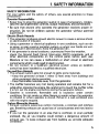
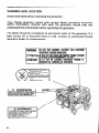
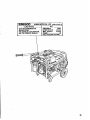
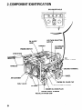
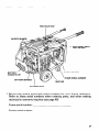
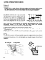
Thank you for purchasing a Honda generator.
This manual describes the operation and maintenance
of the Honda
Generator: EB6500
All information in this publication is based on the latest product information
available at the time of printing.
Honda Motor Co., Ltd. reserves the right to make changes at any time
without notice and without incurring any obligation.
No part of this publication may be reproduced without written permission.
This manual should be considered a permanent part of the generator and
should remaine with it if it is resold.
READ THIS OWNER’S MANUAL
these symbols and any instructions
Indicates
not followed.
serious
CAREFULLY.
that follow:
to
injury or deaUh WUU resuh iff instructions
Indicates a strong possibility
result if instructions
are not followed.
CAUTION:
instructions
Pay special attention
indicates
a possibility
are not followed.
m
Indicates that equipment
instructions
are not followed.
that
Ehat serious
rnino~
are
injury or death may
injury
or property damage
could
could
result
result
if
if
Honda generator is designed to give safe and dependable service if
operated according to instructions.
Operating this generator requires
special effort on your part to ensure your safety and the safety of others.
Using this generator for a purpose not intended may cause injury or
property damage.
Careless operation or misuse may cause injury or property damage.
and understand the owner’s manual before operating this generator.
If a problem should arise, or if you have any questions
generator, see an authorized Honda generator dealer.
about
Read
your
HONDA MOTOR CO., LTD. 1990, ALL RIGHTS RESERVED
1
CONTENTS
1.
2.
3.
4.
5.
6.
7.
8.
9.
10.
1 1.
12.
13.
14.
15.
2
SAFETY INFORMATION.. ........................................................................... .3
COMPONENT IDENTIFICATION ................................................................ .6
PRE-OPERATION CHECK.. ......................................................................... .8
STARTING THE ENGINE ............................................................................ 12
GENERATOR USE ..................................................................................... .17
STOPPING THE ENGINE ........................................................................... .25
0 High altitude operation ......................................................................... .26
MAINTENANCE ......................................................................................... .27
................................................................... .36
TRANSPORTING/STORAGE
TROUBLESHOOTING ...................................... .......................................... .38
WIRING DIAGRAM ................................................................................... .40
SPECIFICATIONS ..................................................................................... .41
HANGER KIT INSTALLATION .................................................................. 42
2 WHEEL KIT INSTALLATION.. .............................................................. .43
BATTERY TRAY KIT ............................................................................... .44
WARRANTY SERVICE.. ........................................................................... .46
‘I. SAFETY INFORMATION
SAFETY
INFORMATION
For your safety
precautions:
Operator
l
l
and the safety
of others,
pay special attention
to these
Responsibility
Know how to stop the generator quickly in case of emergency. Understand the use all generator controls, output receptacls, and connections.
Be sure that anyone who operates the generator receives proper instruction. Do not let children operate the generator without parental
supervision.
Electric Shock Hazards
l
l
l
l
The generator produces enough electric power to cause a serious shock
or electrocution if misused.
Using a generator or electrical appliance in wet conditions, such as rain
or snow, or near a pool or sprinkler system, or when your hands are wet,
could result in electrocution. Keep the generator dry.
If the generator is stored outdoors, unprotected from the weather,
check the Ground Fault Circuit Interrupter
(GFCI) receptacle, and all
other electrical components
on the control panel, before each use.
Moisture or ice can cause a malfunction or short circuit in electrical
components which could result in electrocution.
Do not connect to a building’s electrical system unless an isolation
switch has been installed by a qualified electrician.
Fire and Burn Hazards
l
l
l
The exhaust system gets hot enough to ignite some materials.
-Keep the generator at least 1 meter (3 feet) away from buildings and
other equipment during operation.
-Keep flammable materials away from the generator.
The muffler becomes very hot during operation and remains hot for a
while after stopping the engine. Be careful not to touch the muffler while
it is hot. Let the engine cool before storing the generator indoors.
Gasoline is extremely
flammable and is explosive
under certain
conditions, Do not smoke or allow flames or sparks where the generator
is refueled or where gasoline is stored. Refuel in a well-ventilated
area
with the engine stopped.
Carbon Monoxide
l
l
Hazards
Exhaust contains poisonous carbon monoxide, a colorless and odorless
gas. Breathing exhaust can cause loss of consciousness and may lead to
death.
If you run the generator in an area that is confined, or even partially
enclosed, the air you breathe could contain a dangerous amount of
exhaust gas. To keep exhaust gas from building up, provide adequate
ventilation.
WARNING
LABEL LOCATION
Read these labels before operating the generator.
Your Honda generator comes with several labels containing important
safety information.
Anyone who uses the generator should read and
understand this information before operating the generator.
The labels should be considered as permanent parts of the generator. If a’
label comes off or becomes hard to read, contact an authorized Honda
generator dealer for replacements.
/-
, INDOOR
IDONOTUSE
‘S EXHAUST
GASCON;]
mmwn~~~
L
-,--..--- PARRnN
~~.\YV..JUNOXIDE
ATTENTIONkEPASUTlLlSER
DANSUNENDdOlT
PERME
A CAUSE
DURISQUE
DEMPDISDNNEMENT
DUGAZ.
ATENClON NO LO USEEN LUGARES
CERRADOS
PORDUE
EL
MONOXIDE
DECARBDND
ESVENENDSO.
[N~NG
4
5
2.COMPONENT
IDENTIFICATION
GFCI RECEPTACLE
---I----
\-J
VOLTAGE SELECTOR
SWITCH
OIL ALERT
LAMP
HANGER
ENGINE SWITCH
.\
AC CIRCUIT
I)REAKER
I
AC
RECEPTACLES
GROUND TERMINAL
WHEEL
AIR CLEANER
FUEL VALVE
\
ENGINE OIL FILLER CAP
AUTO-THROTTLE
1 ENGINE OIL DRAIN PLUG
ENGINE SERIAL NUMBER
RECOIL STARTER GRIP
SWITCH
FUEL FILLER CAP
OCCUPANTS
(GFCI)
TEST RECORD
PARK PLUG CAP
GUARD PLATE
FRAME SERIAL NUMBER
BATTERY TRAY
* Record the engine and frame serial numbers for your future reterence.
Refer to these serial numbers when ordering parts, and when making
technical or warranty inquiries (see page 46)
Frame serial number:
Engine serial number:
7
3.PRE-OPERATION CHECK
Engine oil
j-liEiq
l
l
Engine oil is a major factor affecting engine performance
and service
life. Non-detergent
and 2-stroke engine oils are not recommended.
Check the generator on a level surface with the engine stopped.
Use Honda 4-stroke oil, or an equivalent
high detergent, premium quality motor oil
certified
to meet or exceed
U.S.
automobile manufacturer’s
requirements
for Service Classification SG, SF/CC, CD.
Motor oils classified SG, SF/CC, CD will
show this designation on the container.
rs,,,,
-30 -20 -10
0
10
SAE low-30
is recommended for general, all-temperature
use. Other
viscosities
shown,
in the chart may be used when the average
temperature in your area is within the indicated range.
1 .Remove the oil filler cap and wipe the dipstick clean.
2.Check the oil level by inserting the dipstick in the filler neck without
screwing it in.
3.lf the fevel is low, add the recommended oil to the upper mark on the
dipstick.
NOTE:
The Oil Alert system will automatically stop the engine before the oil level
falls below the safe limit. However, to avoid the inconvenience
of an
unexpected shutdown, it is still advisable to visually inspect the oil level
regularly.
OIL FILLER CAP
OIL FILLER HOLE
LEVEL
8
Fuel
Remove the filler cap and check the fuel level. Refill the tank if the fuel
level is low. Do not fill above the shoulder of fuel strainer.
Your engine is designed to use any gasoline that has a pump octane
number (R +MV2 of 86 or higher, or that has a research octane number of
91 or higher. Gasoline pumps at service station normally display the pump
octane number.
We recommend that you use unleaded fuel because it produces fewer
engine and spark plug deposits and extends the life of exhaust system
components.
Never use stale or contaminated gasoline or an oil/gasoline mixture. Avoid
getting dirt, dust or water in the fuel tank.Use of a lower octane gasoline
can cause persistent “pinging” or heavy “spark knock” (a metallic rapping
noise) which, if severe,can lead to engine damage.
If “spark knock” or “pinging”
occurs at a steady engine speed under
normal load, change brands of gasoline. If spark knock or pinging persists,
consult your authorized
Honda dealer. Failure to do so is considered
misuse, and damage caused by misuse is not covered by Honda’s Limited
Warranty.
Occasionally you may hear light spark knock while operating under heavy
loads. This is no cause for concern. It simply means your engine is
operating efficiently.
Fuel tank capacity:
17.0 0 (4.49 US gal , 3.74 Imp gal)
FUEL FILLER CAP
l
l
l
l
l
Gasoline
is extremely
flammable
and is explosive
under certain
conditions.
Refuel in a well-ventilated
area with the engine stopped. Do not smoke
or allow flames or sparks in the area where the engine is refueled or
where gasoline is stored.
Do not overfill the fuel tank (there should be no fuel in the filler neck).
After refueling, make sure the tank cap is closed properly and securely.
Be careful not to spill fuel when refueling. Spilled fuel or fuel vapor may
ignite. lfany fuel is spilled, make sure the area is dry before starting the
engine.
Avoid repeated or prolonged contact with skin or breathing of vapor.
KEEP OUT OF REACH OF CHILREN.
GASOLINES
CONTAINING
ALCOHOL
If you decide to use a gasoline containing alcohol (gasohol), be sure its
octane rating is at least as high as that recommended by Honda. There are
two types of “gasohol”: one containing ethanol, and the other containing
methanol.
Do not use gasohol than contains more than 10% ethanol. Do not use
gasoline containing methanol (methyl or wood alcohol) that dose not also
contain cosolvents
and corrosion
inhibitors
for methanol. Never use
gasoline containing more than 5% methanol, even if it has cosolvents and
corrosion inhibitors.
NOTE:
l Fuel system
damage or engine performance problems resulting from the
use of fuels that contain alcohol is not covered under the warranty.
Honda cannot endorse the use of fuels containing methanol since
evidence of their suitability is as yet incomplete.
l Before
buying fuel from an unfamiliar station, try to find out if the fuel
contains alcohol,if it dose, confirm the type and percentage of alcohol
used.
If you notice any undesirable operating symptoms while using a gasoline
that contains alcohol, or one that you think contains alcohol, switch to a
gasoline that you know does not contain alcohol.
10
=
Air cleaner
Check the air cleaner elements to be sure they are clean and in’good
condition. Clean or replace the element if necessary (page 30).
f-iieiq
Never
result.
run the
engine
without
the
air cleaner.
Rapid engine
wear
will
AIR CLEANER
ELEMENT
11
4.STARTlNG
THE ENGINE
1 .Make sure that the AC circuit breaker is in the OFF position.
generator may be hard to start if a load is connected.
AC ClRCiJlT BREAKER
2. Turn the fuel valve to the ON position.
FUEL VALVE
12
The
3. Pull the choke rod out to the CLOSED position.
NOTE:
Do not use the choke if the engine is warm or if the air temperature
is high.
CHOKE ROD
4. Make sure the auto-throttle
for warm up.
switch
is OFF, or more time will be required
13
5. Start the engine
0 With recoil starter:
Turn the engine switch to the ON position
ENGINE SWITCH
Pull the starter grip lightly until resistance
is felt, then pull briskly.
riiEiq
Do not allow the starter grip to snap back against
gently to prevent damage to the starter or housing.
the engine.
Return
ARTER GRIP
14
it
0 With electric starter
Turn the engine switch to the START position and hold it there for 5
seconds or until the engine starts.
e Operating the starter motor for more than 5 seconds can damage the
motor. If the engine fails to start, release the switch and wait 10
seconds before operating the starter again.
l If the
speed of the starter motor drops after a period of time, it is an
indication that the battery should be recharged.
ENGINE SWITCH
6.When the engine starts,
position
allow the engine switch
to return to the ON
ENGINE SWITCH
15
7. Push the choke rod to the OPEN position as the engine warms up.
CHOKE RO
8. If you wish to use the auto-throttle system, turn the auto-throttle switch
to the AUTO position after the engine has warmed up for 2 or 3 minutes.
AUTO-THROTTLE
SWITCH
16
5. GENERATOR USE
l
l
To prevent
electrical
shock from faulty appliances,
make sure all
appliances are in good working order before connecting
them to the
generator.
Connections
for standby power to a building’s electrical system must
be made by a qualified electrician and must comply with all applicable
laws and electrical codes. Improper connections
can allow electrical
current from the generator to backfeed
into the utility lines. Such
backfeed
may electrocute
utility company
workers
or others who
contact the lines during a power outage, and when utility power is
restored,
the generator
may explode, burn, or cause fires in the
building’s electrical system.
GROUND TERMINAL
l
l
l
Limit operation requiring never exceed the maximum power.
Maximum power is:
6.5 kVA
For continuous operation, do not exceed the rated power of:
5.5 kVA for more than 30 minutes.
In either case, the total wattage of all appliances connected
must be
considered.
Most motorized appliance require more than their rated wattage for
startup.
Do not exceed the current limit specified for any out put.
NOTE:
You can determine an appliance’s VA (volt amp) rating by multiplying
required voltage by the amount of current (amps) it draws.
its
17
Auto-throttle
system
With the switch in the AUTO position, engine speed is automatically
reduced to an idle when all loads are turned off or disconnected. When
appliances are turned on or reconnected, the engine resumes the rated
speed. At OFF, the auto-throttle system does not operate.
NOTE:
l AUTO
is recommended to minimize fuel consumption when no load is
applied.
l The auto-throttle
system will not respond to electrical loads of less than
1 ampere.
l The
system is not-effective
for use with appliances that require only
momentary
power. To avoid extended warm-up periods, keep the
switch OFF until the engine reaches operating temperature.
AUTO-THROTTL
SWITCH
18
Oil alert system
The Oil Alert system is designed to prevent engine damage caused by an
insufficient
amount of oil in the crankcase. Before the oil level in the
crankcase can fall below a safe limit, the Oil Alert system will automatically
stop the engine (the engine switch will remain in the ON position).
If the Oil Alert system stops the engine, the Oil Alert lamp will flash when
you operate the starter, and the engine will not run. If this occurs, add
engine oil (p. 8).
LAMP
19
Circuit
Breaker
The circuit
120/24OV
the circuit
the circuit
is working
the circuit
breaker protects the individual circuit protectors and the 5Oh
receptacle. The circuit breaker will automatically switch OFF it
is overloaded or the appliance plugged into the circuit is faulty. If
breaker is switched OFF automatically, check that the appliance
properly and that it does not exceed the rated load capacity of
before switching the circuit breaker ON again.
CIRCUIT BREAKER
Circuit
Protector
The circuit protectors will automatically switch OFF it the individual circuit
is overloaded or the appliance plugged into the circuit is faulty. If the circuit
protector
is switched
OFF automatically,
check that the appliance is
working properly and that it does not exceed the rated load capacity of the
circuit before resetting the circuit protector.
y>:
, @120/240V-30A
Circuit Protector
,
’
For Receptacle@
For Receptacle@
@120V-20A
20
@12QV-2QA
Groung Fault Circuit
Interrupter
(GFCI) Receptacle
Using the generator in rain, snow or near water
electric shock. Keep the generator dry.
can lead to death from
This receptacle is protected by a Ground Fault Circuit interrupter
protection against electrical shock.
TEST BUTTON
RESET BUTTON
(GFCI) for
To test, depress the “TEST” button
(see page 22)
To restore power, depress the “RESET” button
(see page 23)
Perform this test monthly to ensure proper operation of the GFCI Receptacle. If the generator is stored outdoors, unprotected form the weather,
test the GFCI receptacle before each use. Rcord your test on the GFCI test
card provided on the fuel tank.
TEST BUTTON
RESET BUTTON
21
INSPECTION
Before each use:
If the generator is stored outdoors, unprotected from the weather, test the
GFCI receptacle before each use as described in the monthly inspection.
Monthly:Under
normal operating
conditions,
perform the GFCI test
monthly. Record your test on the GFCI test card provided on the fuel tank.
1. Unplug all appliance’s from the GFCI receptacles.
2. Start the engine.
3. Turn the circuit breaker ON.
4. Make sure the auto-throttle switch is OFF
CIRCUIT BREAKER
5. Press the TEST BUTTON
TEST BUTTON
22
-The
RESET BUTTON should extend
with a click.
-If the REST BUTTON does not extend,
contact
an authorized
Honda
generator dealer.
-The
RESET BUTOON should be
flush with the test button.
-If the RESET BUTTON is not flush
with the TEST BUTOON, contact an
authorized Honda generator dealer.
6. Press the RESET BUTTON
/
RESET BUTTON
7. When the RESET BUTTON extends during operation:
l Unplug all appliance’s
from the GFCI protected receptacle.
l Press the RESET BUTTON:
IF THE GFCI CAN NOT BE RESET:
IF THE GFCI RESETS PROPERLY:
The GFCI is faulty. Contact an authorized Honda generator dealer.
Check the appliance or its cord.
23
AC operation
1. Start the engine.
2. Turn the voltage selector switch to either position as required.
NOTE:
With the voltage selector switch in the “12OV/24OV”
position, you can
use the 120V and 240V receptacles simultaneously.
If you are not using
the 240V receptacle, but you require more power from the 12OV twistlock
receptacle, then turn the switch to the “12OV” position.
3. Switch on the AC Circuit Breaker.
4. Plug in the appliance.
l
l
l
Be sure that appliances
do not exceed the generator’s
rated load
capacity for more than 30 minutes, and that they never exceed the
maximum
load capacity.
Substantial
overloading
will switch off the
circuit breaker. Marginal overloading
may not switch off the circuit
breaker, but it will shorten the service life of the generator.
If an overloaded
circuit causes the AC circuit breaker to switch off,
reduce the electrical load on the circuit, and wait a few minutes before
resetting the circuit breaker.
Be sure that all appliances are in good working order before connecting
them to the generator.
If an appliance begins to operate abnormally,
becomes sluggish, or stops suddenly, turn off the circuit breaker and
the generator
engine
switch
immediately.
Then
disconnect
the
appliance and examine it for signs of malfunction.
VOLTAGE SELECTOR
AC CIRCUIT BREAKER
PLUG
24
6. STOPPIN
NOTE:
To stop the engine in an emergency,
position.
THE ENGINE
turn the engine switch
to the OFF
In normal use:
1. Turn the AC circuit breaker to the OFF position.
AC CIRCUIT BREAKER
2. Move the engine switch to the OFF position.
ENGINE SWITC
25
3.Turn the fuel valve to the OFF position.
FUEL VALVE
l High altitude
operation
At high altitude,
the standard
carburetor
excessively
rich. Performance will decrease,
increase.
air-fuel mixture
will be
and fuel consumption
will
High altitude performance can be improved by installing a smaller diameter
main fuel jet in the carburetor and readjusting the pilot screw. If you always
operate the engine at altitudes higher than 6,000 feet above sea level, have
an authorized Honda generator dealer perform this carburetor modification.
Even with suitable carburetor jetting, engine horsepower will decrease
approximately 3.5% for each 1,000 foot increase in altitude. The effect of
altitude on horsepower will be greater than this if no carburetor modification is made.
Operation of the generator at an altitude lower than the carburetor
is
jetted for may result in reduced performance,
overheating,
and serious
engine damage caused by an excessively
lean air/fuel mixture.
26
7. MAONTENANCE
Periodic maintenance and adjustment is necessary to keep the generator in
good operating condition. Perform the service and inspection scheduled in
the table on the next page.
Shut off the engine before performing any maintenance.
must be run, make sure the area is well ventilated.
Exhaust
poisonous carbon monoxide.
if the engine
gas con-tains
Use only genuine HONDA parts or their equivalent
for maintenance
or
repair. Replacement
parts which are not of equivalent
quality may
damage the generator.
Tool kit
The tools supplied with the generator will help you to perform the
ownermaintenance
procedures listed on the following page. Always keep
this tool kit with the generator.
L
e-
J
SCREW DRIVER
10x 12mmWRENCH
DRIVER HANDLE
PLUG WRENCH
1
,
0
HANDLE BAR
-
I
-3
TOOL BAG
27
Maintenance
schedule
Performed at every indicated month or
operating hour interval, whichever
NOTE:
(1): Service more frequently
when used in dusty areas.
(2): This service should be performed
by an authorized
Honda generator dealer unless the
owner has the proper tools and is mechanically proficient.
28
See the Honda Shop Manual.
Engine oil change
Drain the oil while the engine is warm to assure rapid and complete draining.
1. Remove the drain plug and filler cap, and drain the oil.
2. Retighten the plug securely.
3. Refill with the recommended oil (see page 8 1,and check the level.
Oil capacity:
1 .I !J (I .2 US qt , 1 .O Imp qt)
DRAIN PLUG
CAUTION:
Used motor oil may cause skin cancer if repeatedly left in contact with
the skin for prolonged periods. Although
this is unlikely,
unless you
handle used oil on a daily basis, it is still advisable to thoroughly
wash
your hands with soap and water as soon as possible after handling used
oil.
NOTE:
Please dispose of used motor oil in a manner that is compatible with the
environment. We suggest you take it in a sealed container to your local
service station for reclamation. Do not throw it in the trash or pour it on
the ground.
29
Air cleaner service
A dirty air cleaner will restrict air flow to the carburetor. To prevent
carburetor malfunction, service the air cleaner regularly (page 28 1. Service
more frequently when operating the generator in extremely dusty areas.
Using gasoline or flammable solvent to clean the filter element can cause
a fire or explosion. Use only soapy water or nonflammable
solvent.
Never run the generator
result.
wear
will
1. Unsnap the air cleaner cover clips, remove the air cleaner cover,
remove the element.
and
AIR CLEANER COVER
30
without
the air cleaner.
Rapid engine
AIR CLEANER ELEMENT
2. Wash the element in a solution of household detergent and warm water,
then rinse thoroughly, or wash in nonflammable or high flash point solvent. Allow the element to dry thoroughly.
3. Soak the element in clean engine oil and squeeze out the excess oil.
The engine will smoke during inital start-up if too much oil is left in the
element.
4. Reinstall the air cleaner element and the cover.
ELEMENT
31
Sediment
cup cleaning
The sediment cup prevents dirt or water which may be in the fuel tank
from entering the carburetor. If the engine has not been run for a long time,
the sediment cup should be cleaned.
1 .Turn the fuel valve to the OFF position. Remove the sediment cup.
2. Clean the cup thoroughly.
3. Check to be sure the O-ring is in place, and reinstall the sediment cup.
After installing the sediment cup, check for fuel leaks, and make sure the
area is dry.before starting the engine. Fuel vapor or spilled fuel may ignite.
FUEL VALVE
\
32
SEDIMENT CUP
Spark plug service
Recommended
spark plugs:
BPR5ES (NGK)
W 1 GEPR-U (ND)
To ensure proper engine operation,
gapped and free of deposits.
the
If the engine has been runnig, the muffler
to touch the muffler.
spark
plug must
be properly
will be very hot. Be careful
not
1. Remove the spark plug cap.
2. Clean any dirt from around the spark plug base.
3. Use the wrench supplied in the tool kit to remove the spark pulg.
4.Visually inspect the spark plug. Discard it if the insulator is cracked or
chipped. Clean the spark plug with a wire brush if it is to be reused.
5. Measure the plug gap with a feeler gauge.
Correct as necessary by carefully bending the side electrode.
The gap should be:
0.70-0.80
mm (0.028-0.031
in)
0.70-0.80
mm
(0.028-0.031
in)
33
6.Check that the spark plug washer is in good condition,
spark plug in by hand to prevent cross-threading.
7.After each spark plug is seated, tighten
compress the washer.
with
and thread the
a spark plug wrench
to
NOTE:
If installing a new spark plug, tighten l/2 turn after the spark plug seats to
compress the washer. If reinstalling a used spark plug, tighten l/8 - l/4
turn after the spark plug seats to compress the washer.
l
l
The spark plug must be securely tightened.
An improperly tightened
spark plug can become very hot and could damage the engine.
Never use spark plugs which have an improper heat range. Use only
the recommended
spark plugs or equivalent.
34
Spark arrester
maintenance
If the generator has been running,
cool before proceeding.
Thespark
efficiency.
arrester
must
the muffler
be serviced
every
will be very hot. Allow
IQ0
hours
to maintain
it to
its
Clean the spark arrester as follows:
1. Loosen the screw by the exhaust port of the muffler and remove the
spark arrester.
2. Use a brush to remove carbon deposits from the spark arrester screen.
Inspect the screen for breaks or tears and replace it if necessary.
3. Install the spark arrester in the reverse order of removal.
SPARK ARRESTER
SCREEN
\
SPARK ARRESTER
35
8.TRANSPORTINGISTORAGE
When transporting
the generator,
turn the engine switch
valve OFF and keep the generator
level to prevent fuel
vapor or spilled fuel may ignite.
and the fuel
spillage. Fuel
Before storing the unit for an extended period:
1. Be sure the storage area is free of excessive humidity and dust.
2. Drain the fuela. With the fuel valve OFF, remove and empty the sediment cup.
FUEL VALVE
SEDIMENT CUP
b.Turn the fuel valve ON, and drain the gasoline in the fuel tank into a
suitable container.
c. Replace the sediment cup and tighten securely.
36
d.Drain the carburetor by loosening the drain screw. Drain the gasoline
into a suitable container.
Gasoline
is
conditions.Do
extremely
flammable
and is explosive
under
not smoke or allow flames or sparks in the area
certain
DRAIN SCREW
3.Change the engine oil.
4.Remove the spark plug, and pour about a tablespoon of clean engine oil
into the cylinder. Crank the engine several revolutions to distribute the
oil, then reinstall the spark plug.
5.Slowly pull the starter grip until resistance is felt. At this point, the
piston is coming up on its compression stroke and both the intake and
exhaust valves are closed. Storing the engine in this position will help to
protect it from internal corrosion.
the notch on the starter pulley
the hole at the top of recoil starter.
6.Cover the engine to keep out dust.
37
9.TROUBLESHOOTING
A.When the engine will not start:
.I. Is the engine switch on?
2. Does the oil alert lamp flash when the starter is pulled?
3. Is there enough fuel?
4. Is the battery full charged when starter motor does not start?
5. Are all loads disconnected from the AC receptacles?
6. Is there a spark at the spark plug?
a. Remove the spark plug cap. Clean any dust from around the spark
plug base, then remove the spark plug.
b. Install the spark plug in the plug cap.
c. Turn the engine switch on.
d. Grounding the side electrode to any engine ground, pull the recoil
starter to see if sparks jump across the gap.
Be sure there
is no spilled fuel around
ignite. Perform
this test in a well ventilated
the spark
plug. Spilled fuel may
area.
e. If there are no sparks, replace the plug.
f. If the new spark plug does not spark, take the generator
authorized Honda dealer.
ENGINE SWITCH
38
to an
6. Is gasoline reaching the carburetor?
To check, place a suitable container under the drain tube, turn the fuel
valve on and loosen the drain screw. Fuel should flow out freely.
If OK, try to start the engine according to the instructions.
If any fuel is spilled, make sure the area around
generator is dry before starting the engine.
Fuel vapor or spilled fuel may ignite.
the spark plug and the
DRAIN SCREW
7. If the engine still does not start, take the generator
Honda dealer.
to an authorized
B.When the engine starts but stops immediately;
1. Check the oil alert lamp.
If the oil alert lamp flashes when the starter is pulled, check the engine
oil level and fill with the recommended oil.
2. Re-start the engine.
C.No electricity at the AC receptacles:
1. Is the AC circuit breaker on?
2. Check the electrical appliance or equipment for any defects.
39
IO. WIRING DIAGRAM
1 ‘I. SPECIFICATIONS
Dimensions
Power
product description
code
EZCH
Length
Width
1,200 mm (47.2 in)
665 mm (26.2 in)
Height
720 mm (28.3
98.5 kg (217.2
Dry weight
in)
Ibs)
Engine
Engine Type
Gk390
Displacement
389
[Bore x Stroke]
1 Comoression Ratio
Engine Speed
Cooling System
Ignition System
Oil Capacity
Fuel Tank Capacity
Soark Plua
cm3 (23.7
cu-in)
r88 x 64 mm (3.5 x 2.5 in)
8.0 : 1
3600 r.p.m.
Forced air
Transistorized
magneto
1 .l 0 (1.2 US qt , 1 .O Imp qt)
17.0 !J (4.49 US gal , 3.74 Imp gal)
BPR5ES (NGK)
W 1 GEPR-U (ND1
Generator
AC output
Rated Voltage
Rated Frequency
Rated Ampere
Rated Output
Maximum Output
1201240 V
60 Hz
45.8122.9
5.5 kVA
A
6.5 kVA
41
12. HANGER KIT INSTALLATION
1. Remove the upper frame. Install the hanger on it and install the upper
frame on the body.
BRACKET
HANGER
/
%
FRAME
NOTE:
Install at near center avoiding to install over the fuel filler cap.
FUEL FILLER CAP
I
I
42
13. 2-WHEEL KIT INSTALLATION
1. Install the two wheels on the axle shaft.
2. Install the axle assembly on the generator using two bolts and nuts.
3. Install the two stands on the under frame.
WHEELS
4.Remove the upper frame. Install the two handles with brackets on it
using six bolts and install the upper frame on the body using four bolts.
HANDLE
43
14. BATTERY TRAY KIT
1. Install the battery guard on the frame.
Set the battery tray on the battery guard and tighten the bolts.
2. Route the starter cable under the tank and connect it to the starter
solenoid.
3. Connect the ground cable to the generator rear housing.
4. Set the battery on the battery tray and secure with the battery bracket.
Connect the starter cable to the battery positive (+I terminal first, then
to the negative (-1 terminal. When disconnecting,
disconnect at the
battery negative (-1 terminal first.
5. Install the battery guard plate on the battery guard.
STARTER
SoLEINo’D
STARTER CABLE
(positive)
STARTER CABLE
I
BATTERY
BRACKET
BATTERY GUARD
GUARD PLATE
BATTERY
TRAY
45
15. WARRANTY
Owner
SERVICE
satisfaction
Your satisfaction and goodwill are important to your dealer and to us. All
Honda warranty details are explained in the Distributor’s Limited Warranty.
Normally, any problems concerning the product will be handled by your
dealer’s service department. If you have a warranty problem that has not
been handled to your satisfaction,
we suggest you take the following
action:
l
l
Discuss your problem with a member of dealership management. Often
complaints can be quickly resolved at that level. If the problem has
already been reviewed with the Service Manager, contact the owner of
the dealership or the General Manager.
If your problem still has not been resolved to your satisfaction,
American
Honda
P.O. Box 100021
Motor
contact:
Co., Inc.
Duluth, Georgia 30136-9421
Telephone: (404) 497-6400
We will need the following
information
-Your
name, address, and telephone
-Product
model and serial number
-Date of purchase
-Dealer name and address
-Nature
of the problem
in order to assist you:
number
After reviewing all the facts’ involved, you will be advised of what action
can be taken. Please bear in mind that your problem will likely be resolved
at the dealership, using the dealer’s facilities, equipment, and personnel, so
it is very important that your initial contact be with the dealer.
Your purchase of a Honda product is greatly appreciated by both your
dealer and American Honda Motor Co.,lnc. We want to assist you in every
way possible to assure your complete satisfaction with your purchase.
46
MEMO
47
MEMO
48