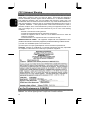
1
Hitachi America, Ltd. warrants our Hitachi CRT color monitor to be free from defects in
material and workmanship for 36 months from the date you purchased it if your purchase
was made prior to 1/31/01 or 60 months if your purchase was made after 1/31/01 from
your
authorized
Hitachi
America,
Ltd.
dealer.
If you purchase a Hitachi Liquid Crystal Display (LCD) color monitor, Hitachi provides a
warranty of 36 months for the panel and 12 months for the backlight if purchased before
1/31/01 or 36 months for both panel and backlight if purchased after 1/31/01. In the
event of a defect during this 12 month, 36 month or 60 month period, Hitachi America,
Ltd. will, at its option, repair or replace the monitor at no charge except as set forth
below. If proof of purchase cannot be provided by owner, the warranty period will start to
run from the date of manufacture.
Hitachi America, Ltd. may repair your monitor with new or reconditioned parts or replace
it with a new or reconditioned monitor of the same or similar kind, and any replaced
monitors or parts become Hitachi America, Ltd.'s property.
Exclusions from this warranty: It is normal for Cathode Ray Tube (CRT) monitors and
LCD display backlights to decrease in brightness as they age. This is a natural process
in CRTs & LCDs due to the degradation of the LCD backlight and the degradation of the
CRT phosphors that create the image and is not covered by this warranty. This warranty
excludes decreased image clarity or reduced brightness due to natural aging of the
monitor/display. In addition, this warranty does not cover phosphor burn. Phosphor burn
can occur when a monitor is left with one static image for extended periods of time
during which the image may become burned into the phosphors.
This limited warranty does not cover damage occurring in shipping or in storage after you
purchase the monitor or damage caused by abuse, accident, disaster, misuse,
mishandling, mispackaging or shipping, improper installation, unauthorized repair or
modification, or failure to follow the manufacturer's instruction with respect to the proper
handling, operation, installation, service and maintenance of the monitor.
To obtain warranty service, call 1-800-536-6721 to obtain a return authorization and the
location of your Hitachi service center or return the monitor to the dealer from whom you
bought it (subject to that dealers' return policy). If you choose to ship the monitor rather
than delivering it in person, you must assume the risk of damage or loss in transit. You
must also use the original shipping container (or equivalent packaging), pay shipping
charges, and enclose a copy of the proof of purchase date with the monitor.
For additional information, please write to:
Hitachi America, Ltd.
200 Lowder Brook Drive, Suite 2200, Westwood, MA 02090
NEVER open the monitor cabinet. If the monitor is not operating properly, contact
Hitachi
America
Ltd.
service
center
(Call
1-800-536-6721).
Do not open the monitor housing under any circumstances. By opening the monitor
housing you will expose yourself to high voltage and possible severe electrical shocks
and void all warranties.
1
ENGLISH
Limited Warranty for USA Customers Only
ENGLISH
ANY IMPLIED WARRANTY OF MERCHANTABILITY OR FITNESS FOR A
PARTICULAR PURPOSE ON THIS MONITOR IS LIMITED TO THE 12, 36 or 60
MONTH DURATION OF THIS WRITTEN WARRANTY, AS APPLICABLE.
ALL
WARRANTIES SET FORTH IN THIS WARRANTY ARE LIMITED TO 12, 36 OR 60
MONTHS FROM THE DATE OF PURCHASE. NO WARRANTIES WHATSOEVER WILL
COVER THIS MONITOR BEYOND THE STATED 12, 36 OR 60 MONTHS. HOWEVER,
SOME STATES DO NOT ALLOW LIMITATIONS ON HOW LONG AN IMPLIED
WARRANTY LASTS, SO THE ABOVE LIMITATION MAY NOT APPLY TO YOU.
IF THIS MONITOR IS DEFECTIVE, YOUR ONLY REMEDY IS REPAIR OR
REPLACEMENT, AS DESCRIBED ABOVE. UNDER NO CIRCUMSTANCES WILL
HITACHI AMERICA, LTD. BE LIABLE FOR INCIDENTAL OR CONSEQUENTIAL
DAMAGES, INCLUDING ANY LOST SAVINGS, LOST PROFITS, OR ANY OTHER
DAMAGES CAUSED BY THE USE OF THIS MONITOR OR INABILITY TO USE IT,
EVEN IF THE DEALER OR HITACHI AMERICA, LTD. HAS BEEN ADVISED OF SUCH
LIABILITY OR OTHER CLAIMS.
SOME STATES DO NOT ALLOW THE EXCLUSION OR LIMITATION OF INCIDENTAL
OR CONSEQUENTIAL DAMAGES SO THE ABOVE LIMITATION OR EXCLUSION MAY
NOT APPLY TO YOU. THIS WARRANTY GIVES YOU SPECIFIC LEGAL RIGHTS,
AND YOU MAY HAVE OTHER RIGHTS WHICH VARY STATE TO STATE.
THIS WARRANTY APPLIES TO NEW, CURRENT, PRODUCTS ONLY AND
DOES NOT APPLY TO PRODUCTS SOLD AFTER THEY ARE
DISCONTINUED OR REFURBISHED.
For Canadian Customers only Warranty Policy
Hitachi Industrial Products are guaranteed to be free from defects in workmanship and
material. If any failure, resulting from either workmanship or material defects should
occur under normal and proper usage within the period stated hereunder from the
original provable date of purchase, such failure should be repaired at no cost to the
buyer for labor and parts if the defective product is brought to an AUTHORIZED HITACHI
SERVICE CENTRE in Canada.
WARRANTY PERIOD
COMPUTER MONITOR
3 year parts and 3 year labour
WARRANTY DOES NOT COVER
1.
Products received for repair without sales or delivery receipt showing date of
purchase by original customer.
2.
Damages caused by incorrect use, carelessness, unauthorized alteration, improper
storage or unauthorized service or repairs.
3.
Damages caused by fire, flood, lightning, vandalism, collision, acts of God, or other
events beyond the control of Hitachi.
2
External parts such as cabinet.
5.
Products purchased outside Canada.
6.
Products used outside Canada.
7.
In transit damage claims, improper handling by carrier or post offices.
8.
Products or parts there of which have serial numbers removed, altered or defaced.
9.
Damage defect or failure caused by, or resulting from, the operation of the unit by
incorrect voltages.
10. The use of components that do not meet Hitachi specifications.
11. Products sold in Canada by another organization which is not authorized by
HITACHI CANADA LTD
12. Picture tube damages resulting from extended exposure of the video characters.
IMPORTANT : This warranty is in lieu of all other warranties, guarantees or agreements
whether expressed or implied and no person, dealer, or Company is authorized to
change, modify, or extend its terms in any manner whatsoever.
Hitachi Canada Inc. shall not be responsible for any damages or loss of any kind
attributed to the product rendered defective during usage, or attributed to incompatibility
problems of any linked equipment including software.
NEVER open the monitor cabinet. If the monitor is not operating properly, contact Hitachi
Service Center. DO NOT open the monitor housing under any circumstances. by opening
the monitor housing you will expose yourself to high voltage and possible severe
electrical shocks, and void all warranties.
HITACHI CANADA LTD.
For service, please call your Dealer or your 1-800-HITACHI.
TRONTO
6740 Campobello Road, Mississauga, Ont. L5N 2L8
Tel.: (905) 821-4545
Fax No.: (905) 821-1101
3
ENGLISH
4.
Colour/Color Monitor
ENGLISH
CML152XW
USER MANUAL
Congratulations on your selection of the HITACHI Colour/Color Monitor.
Read the instructions inside carefully, and keep this user manual for future reference.
NOTE:
* The information in this manual is subject to change without notice. The
manufacturer assumes no responsibility for any errors that may appear in this
manual.
* The reproduction, transmission or use of this documents or contents is not
permitted without express written authority.
TRADEMARK ACKNOWLEDGEMENT:
VGA is a registered trademark of International Business Machines Corporation.
VESA is a trademark of a nonprofits organization, Video Electronics Standard
Association.
®
ENERGY STAR is a trademark of Environmental Protection Agency (EPA).
CONTENTS
USING THIS DISPLAY SAFELY ........................................................................................... 6
W ARNING..................................................................................................................... 7
CAUTION .................................................................................................................... 10
FCC STATEMENT W ARNING ............................................................................................... 12
FOR THE CUSTOMERS IN CANADA.................................................................................... 12
FOR THE CUSTOMERS IN THE UK ........................................................................................ 13
CHAPTER 1 INSTALLATION.............................................................................................. 14
UNPACKING........................................................................................................................ 14
VIEWING ANGLE ADJUSTMENT ............................................................................................ 14
CABLE INSTALLATION .......................................................................................................... 15
CONNECTING THE DISPLAY TO YOUR COMPUTER ................................................................. 16
CONNECTING THE AC POWER ............................................................................................ 17
CONNECTING THE AUDIO CABLE ......................................................................................... 18
SETTING UP THE LCD MONITOR ......................................................................................... 18
POWER MANAGEMENT SYSTEM........................................................................................... 18
CHAPTER 2 DISPLAY CONTROLS .................................................................................. 19
USER CONTROLS ............................................................................................................... 19
ADJUSTING THE MONITOR 'S DISPLAY................................................................................... 20
4
FUNCTION DESCRIPTIONS ................................................................................................... 21
SPECIFICATIONS ................................................................................................................. 24
STANDARD TIMING T ABLE ................................................................................................... 27
TROUBLESHOOTING............................................................................................................ 28
5
ENGLISH
CHAPTER 3 TECHNICAL INFORMATION ....................................................................... 24
Using this Display Safely
ENGLISH
Common Safety Precautions
Please read carefully and make sure you fully understand the following safety
precautions:
- Operations should be done according to instructions and procedures described in
this manual.
- Make sure to heed all warnings displayed on the device and manual. Neglecting to
do so may result in fire or damage the device.
Symbols
Safety notifications are presented as shown below. These are indicated by “Warning”
and “Caution” in combination with a caution symbol (graphic symbol). Additionally,
details are depicted within the graphic symbols.
Warning
This symbol is used to indicate a hazard that may result in death
or grave injury.
Caution
This symbol is used to indicate a hazard that may result in minor
injury or significant damage to the product
[ Notice example 1] Shock Caution
This (?) symbol indicates that caution should be taken and within
the triangle (?) is a picture depicting “Shock caution”.
[Notice Example 2] Disassembly Prohibited
In the ( ? ) barred circle is an action that must not be done and
the picture in this ( ? ) one depicts “Disassembly Prohibited”.
[Notice Example 3] Unplug power Cord from Socket
In the (?) symbol is an action that should be taken. This (?) one
is a picture depicting “ Unplug Power Cord from Socket’ and other
mandatory actions.
Handling and Operation
Do not handle or operate in ways other than what is depicted in the manual. If there are
any problems with the device, turn OFF the power, unplug the cord then notify the dealer
where the product was purchased or call a service person.
Taking ample care
The cautions noted on the device and manual have been carefully considered. Even so,
unforeseen incidents may happen. When operating the device, in addition to following
instructions, takes ample care during handling and operation.
6
Abnormal heat, smoke, sounds or smells.
If anything abnormal should happen, turn OFF the power and unplug the power
cord. Continued use in this condition may lead to electrical shock or fire. The area
around the cord should be clear to allow the cord to be easily unplugged.
Repair, Modification, Disassembly
DO NOT attempt to repair, modify or disassemble the product. This may result
in fire or electrical shock.
Air vents
- The air vents are to prevent the internal temperature from rising. To not place items
on or so that they block the air vents. Also do not place in racks where the air vents
will be blocked. This will cause the internal temperature to rise and result in fire or
malfunction.
- Do place on racks that fix the display in leaning position. This will change the flow of
air through the air vents and cause the internal temperature to rise resulting in fire or
malfunction.
Placing
Objects
in
Device
DO NOT put paper clips, pins, metallic objects or combustible items in the ventilation
holes. Using the device in this condition may result in electrical shock or fire.
Removing the Case Cover
DO NOT remove the case cover. There are many high voltage parts inside and are very
dangerous.
Placing Objects on the Device
DO NOT put flower vases, planters, vessels containing water, pins and paper clips or
other metal items on the device. If anything should fall in, using the product in this
condition may result in electrical shock.
7
ENGLISH
Warning
Handling of the power cord
ENGLISH
Use the power cord supplied with the product and be careful of the following during use.
If handled improperly, the cord may be damaged resulting in electrical shock or fire.
Never place objects on it.
- DO NOT pull
- DO NOT apply pressure
- DO NOT fold
- DO NOT wrap
DO NOT use next to heating device
Plugging and Unplugging
- When plugging or unplugging the power cord in the socket, make sure to hold the
plug. Pulling on the power cord may cause a partial breakage resulting in fire.
- When taking a holiday or vacation and leaving the device unused for prolonged
periods, unplug the power cord. Leaving it plugged in may result in fire.
- When unplugging or plugging in the power cord, insure that your hands are dry.
Handling with wet hands may result in electrical shock.
Poor Electrical Contact in Electric Plug, etc.
The following must be done to prevent bad contact in the electrical plug that may result
in fire.
- Insure that electric plug is inserted in fully.
- Check to see if there is no dust accumulated on the plug before plugging in.
- DO NOT use a socket that is loose or wobbles.
Impact from Dropping
To not drop, bang or subject to physical shock. Using after such incidents may result in
electrical shock or fire.
Power Usage
The usable voltage is 100-120V / 200-240VAC. DO NOT use any other voltage. This
may result in electrical shock or fire.
8
Handling the AC adapter
- DO NOT use with devices other than this display. This may result in shock, fire, or
damage to the device.
- DO NOT use or place in areas where heat accumulates. This may result in fire.
Multi-Tap Usage
TO not attach multiple extension plugs into one outlet. This may result in fire and
overloading lines will activate the circuit breakers causing data loss or damage to the
product.
Usage in Humid or Dusty Areas
DO NOT use or store in areas that are humid, dusty or have abundant moisture such as
a bathroom. This may cause fire or electrical shock.
Moving to Areas of Different Temperature
Moving the device to areas that are very different in temperature may cause
condensation on the outside and internally. Using the device in this condition may result
in fire or electrical shock. Leave the device at the location for a few hours before using.
Aluminium Electrolysis Condenser
The electrolyte condenser used in the AC adapter has a limited life. If used past the life
span (approximately 5 years), replace the AC adapter. Leakage or drying up of the
electrolyte liquid may result in fire, electrical shock. This may also cause the device itself
to malfunction.
Damage to the Display Unit
- Liquid may leak out of the display when damaged. DO NOT touch the liquid. If you
should touch the liquid, wash your hands thoroughly with water. If the liquid should
get into your mouth or eyes, gargle or rinse your eyes and promptly see a doctor for
treatment.
- The display unit is made of glass. If the display unit should break, avoid handling the
glass fragments. The fragments are dangerous and can cause injury.
9
ENGLISH
- DO NOT wet or handle with wet hands. This may result in electrical shock.
CAUTION
ENGLISH
Contact with Metal and Other Edges
When moving the computer be careful when coming in contact with the plastic and metal
edges. It is possible to be injured.
Use in Unstable Places
DO NOT place on sloping or narrow areas that are unstable. The device may drop or fall
and cause injury.
Display Cable
- Arrange the cables so that they are out of the way. If a cable is tripped on, it may
cause injury and damage to the connected devices.
- DO NOT place heavy objects on the cable. Additionally, do not place objects that
generate heat near the cables. The cable casing may break and cause damage to
the devices that are connected.
Stand
- When adjusting the angle, hold the top left and right edges with both hands and
move slowly. Using only one hand may cause it to fall.
- DO NOT place your hand near the stand when adjusting the LCD forward or back.
Your fingers may get caught and cause injury.
Eyestrain
When continuously looking at the display while working, keep the work area lighted at
300 – 1000 Lexes. Additionally, for every hour of work, rest 10 to 15 minutes.
Continuously looking at the display for prolonged periods will cause accumulated eye
fatigue.
Disposal of this Product
When disposing of this product, confer with the dealer where this product was purchased
or refer to laws of the local government or regulations regarding disposal.
10
If used in the vicinity of other electronic devices, they may interfere with each other’s
performances. Especially for devices such as radios and televisions, noise may enter
their sound reception. If this should happen, try the following:
- Place in a location as far away from radios and televisions as possible.
- Change the facing of the antenna on the radio or television.
- Use a different electrical socket.
Storing the Plastic Bag
Keep the plastic bag used to wrap the display away from young children. The bag may
cause suffocation.
11
ENGLISH
Electronic Interference
FCC Statement Warning
WARNING : This equipment has been tested and found to comply with the limits for a Class B
ENGLISH
digital device, pursuant to Part 15 of the FCC Rules. These limits are designed to
provide reasonable protection against harmful interference in a residential installation.
This equipment generates, uses, and can radiate radio frequency energy and, if not
installed and used in accordance with the instructions, may cause harmful interference to
radio communications. However, there is no guarantee that interference will not occur in
a particular installation. If this equipment does cause harmful interference to radio or
television reception, which can be determined by turning the equipment off and on, the
user is encouraged to try to correct the interference by one or more of the following
measures:
- Reorient or relocate the receiving antenna.
- Increase the separation between the equipment and receiver.
- Connect the equipment into an outlet on a circuit different from that to which the
receiver is connected.
- Consult the dealer or an experienced radio / TV technician for help.
INSTRUCTIONS TO USERS : This equipment complies with the requirements of FCC
(Federal Communication Commission) equipments provided that following conditions are met.
(1) Power cord: Unshielded power cord must be used.
(2) Video inputs: The input signal amplitude must not exceed the specified level.
CAUTION : Changes or modifications not expressly approved by the party responsible
for compliance could void the user’s authority to operate the equipment.
For the Customers in CANADA
NOTICE : This Class B digital apparatus complies with Canadian ICES-003.
12
THIS PRODUCT IS SUPPLIED WITH A TWO PIN MAINS PLUG FOR USE IN
MAINLAND EUROPE. FOR THE UK PLEASE REFER TO THE NOTES ON THIS
PAGE.
IMPORTANT FOR UNITED KINGDOM
WORDING FOR CLASS I EQUIPMENT INSTRUCTION BOOKS AND LABELS
The mains lead on this equipment is supplied with a moulded plug incorporating a fuse,
the value of which is indicated on the pin face of the plug. Should the fuse need to be
replaced, an ASTA or BSI approved BS 1362 fuse must be used of the same rating. If
the fuse cover is detachable never use the plug with the cover omitted. If a replacement
fuse cover is required, ensure it is of the same colour as that visible on the pin face of
the plug. Fuse covers are available from your dealer.
DO NOT cut off the mains plug from this equipment. If the plug fitted is not suitable for
the power outlets in your home or the cable is too short to reach a power outlet, then
obtain an appropriate safety approved extension lead or consult your dealer.
Should it be necessary to change the mains plugs, this must be carried out by a
competent person, preferably a qualified electrician.
If there is no alternative to cutting off the mains plug, ensure that you dispose of it
immediately, having first removed the fuse, to avoid a possible shock hazard by
inadvertent connection to the mains supply.
WARNING: THIS EQUIPMENT MUST BE EARTHED
IMPORTANT:
The wires in the mains lead are coloured in accordance with the following code:
Green and Yellow = Earth, Blue = Neutral, Brown = Live.
As these colours may not correspond with the coloured markings identifying the
terminals in your plug, proceed as follows:
The wire which is coloured GREEN and YELLOW must be connected to the terminal in
the plug which is marked with the letter E or by the earth symbol
or coloured GREEN
or GREEN and YELLOW.
The wire coloured BLUE must be connected to the terminal marked with the letter N or
coloured BLUE or BLACK. The wire coloured BROWN must be connected to the
terminal marked with the letter L or coloured BROWN or RED.
13
ENGLISH
For the Customers in the UK
Chapter 1 Installation
ENGLISH
Unpacking
Before unpacking the LCD Monitor, prepare a suitable workspace for your Monitor and
computer. You need a stable and clean surface near a wall power outlet. Make sure that
the LCD Monitor has enough space around it for sufficient airflow. Though the LCD
Monitor uses very little power, some ventilation is needed to ensure that the Monitor
does not become too hot.
After you unpack the LCD Monitor, make sure that the following items were included in
the box:
?
LCD Monitor
?
1.5M Monitor-to-PC signal Cable
?
1.5M Stereo Jack Audio Cable
?
1.8M Power Cord
?
User's Manual
?
AC Adapter
If you find any of these items are missing or appears damaged, contact your dealer
immediately.
Viewing Angle Adjustment
The LCD Monitor is designed to allow the users to have a comfortable viewing angle.
The viewing angle can be adjusted as follows: Top (-5°~ +15°) & Left / Right (-45° to
+45°).
+15
-5
+45
-45
Figure 1-1
WARNING
DO NOT force the LCD Monitor over the maximum viewing angle settings as stated
above. In such an event, you will damage the monitor and the monitor stand.
14
Cable Installation
from the rear of the monitor. (See Fig. 1-2)
1.
Remove the back panel
2.
Remove the rear support panel
1-2)
3.
Place the signal cable, the DC power cable and the audio cable into correct
grooves (See Fig. 1-3).
from the swivel base support column. (See Fig.
1
Figure 1-2
Figure 1-3
15
ENGLISH
Please follow these instructions to install the cables.
Connecting the Display to your Computer
ENGLISH
1.
Power off your computer.
2.
Connect one end of the signal cable to the LCD Monitor's VGA port. (See Fig. 1-4)
3.
Connect the other end of the signal cable to the VGA port on the PC.
4.
Make sure both connections are secure.
Figure 1-4
ATTENTION
This device must be connected to an off-the-shelf video cable in order to comply with
FCC regulations. A ferrite-loaded interface cable is included in the LCD Monitor package.
This device will not be in compliance with FCC regulations when a non-ferrite-core video
cable is used.
16
1.
Connect the power cord to the AC adapter. (See Fig. 1-5)
2.
Connect the AC adapter's DC output connector to the DC Power Jack of the
monitor.
3.
Connect the power cord to an AC power source
Figure 1-5
WARNING
Please install a "Surge Protector" device between the AC Adapter and the electrical wall
outlet for added protection against power surges to prevent the effects of sudden voltage
variations from reaching the LCD Monitor. Sudden power surges may damage your
monitor.
17
ENGLISH
Connecting the AC Power
Connecting the Audio Cable
ENGLISH
1.
Connect the audio cable to the " LINE OUT " jack on your PC's audio card DVD
Rom or to the front panel's “AUDIO OUT” jack of your CD ROM drive. (See Fig. 16)
2.
Connect the other end of the audio cable to the LCD Monitor's " LINE IN " jack.
Figure 1- 6
Setting Up the LCD Monitor
1.
Make sure the AC Adapter is connected to the LCD Monitor.
2.
Turn on the LCD Monitor's power switch, located on the bezel of the monitor.
Power Management System
This LCD Monitor complies with the VESA DPMS (version 1.0) Power Management
guidelines. The VESA DPMS provides four power saving modes through detecting a
horizontal or vertical sync. signal.
When the LCD Monitor is in power saving mode, the monitor screen will be blank and the
power LED indicator colour shows.
18
Chapter 2 Display Controls
ENGLISH
User Controls
A brief description and the location of all LCD Monitor function controls and indicators:
Figure 2-1
1
Stereo Speakers
PC Audio Stereo output.
2
Speaker Volume
Control
Increase Volume - Turn knob clockwise.
Decrease Volume - Turn knob counter clockwise
3
DC Power Switch
Press the power switch to switch the monitor ON/OFF.
4
DC Power-On
Indicator
LED is Green --- Power is ON.
LED is Off --- Power is OFF.
LED is Yellow --- Monitor is in "Power Saving Mode".
5
Function Select
Buttons
Press either left or right control button for OSD (On Screen
Display) menu selection.
6
Adjustment Control
Buttons
Press the left button to decrease the OSD setting and press
the right button to increase the OSD setting.
7
External Headphone
Jack
The monitor speakers will be disabled when using an
external headphone or external speakers.
19
Adjusting the Monitor's Display
The monitor has four function control buttons to select among functions shown on OSD
menu, designed for easy user-viewing environments.
ENGLISH
OSD Function Menu
To access OSD Main menu, simply press one of the Function Select Control buttons,
and the menu diagram will pop up on the screen as shown below:
Continue pressing the Function Selection Control buttons to scroll through the entire
menu items.
Attention
Firmware revision may have been updated into a latest version while the version number
shown on all OSD menus in this manual will stay as Ver. 1.00
20
Brightness
256 scales of brightness are available to choose
from 0 to 255.
This function increases or decreases the
brightness of the image.
Contrast
256 scales of contrast are available to choose
from 0 to 255.
This function increases or decreases the
difference between the dark and light colors.
Horizontal Position
This function shifts the entire display image left
or right.
Vertical Position
This function shifts the entire display image up
or down
Phase
A total of 32 scales (0 to 31) are available to
adjust the focus and clarity of the display.
21
ENGLISH
Function Description
ENGLISH
Clock
This function carries a frequency tracking
feature that offers the user to have better
stability and clarity. Increasing Clock value can
be up to +64 scales. The number of decreasing
Clock (minus) is depending on the input timing.
Auto Adjustment
This function will adjust the display size
automatically to fit full screen.
ATTENTION
In case BEAT noise happened, please press
Auto Adjustment Key to minimize this symptom,
and fine tune with PHASE function manually.
OSD Horizontal Position
This function moves the OSD menu window left
and right.
OSD Vertical Position
This function moves the OSD menu window up
and down.
Graphics Text
This function is to choose a display that allows
maximum graphics text quality. The resolution
selection can either be 640 x 400 or 720 x 400.
Please refer to Chapter 3 “ Standard Timing”
Table for of different timing modes.
22
Recall
ENGLISH
The recall function will return all adjusted
parameters to factory preset values.
Language
Five OSD language options are available:
English, German, French, Spanish, and Italian.
Press the left or right adjustment control button
to select other language.
Colour Temp
Push the (+ -) button to select a different colour
temperature. Please see the diagram below for
function and description.
Icon
Function
Description
9300
CIE coordinated Colour Temperature
of 9300 K
Sets the CIE coordinate colour
temperature to 9300 K
6500
CIE coordinated Colour Temperature
of 6500 K
Sets the CIE coordinate colour
temperature to 6500 K
User
Three colours (Red, Green, Blue) can
be adjusted from the OSD menu
Sets the settings to a by user
defined CIE Temperature.
Save + Exit
Saves the values of this setting and exits the
OSD menu function.
23
Chapter 3 Technical Information
Specifications
ENGLISH
LCD Panel
Size
Display Type
Resolution
Display Dot
Display Area (mm)
Display Colour
Brightness
Contrast Ratio
Response Time
Lamp Voltage
Lamp Current
Viewing Angle
Display Colours
Video
Input Signal
Input Impedance
Polarity
Amplitude
Multi-mode Supported
15.0" (38 cm)
Active matrix colour TFT LCD
1024 x 768
1024 x (RGB) x 768
304 x 228 (H x V)
262K
2
200 cd/m (typical)
250: 1 (typical)
(10 + 40) ms (typical)
640 Vrms (typical)
6.0 mA rms. (Typical)
Vertical: -45° ~ +40°
Horizontal: -60° ~ +60°
16.7M with FRC or Dithering
Analogue RGB 0.7Vp-p
75 Ohm ± 2%
Positive
0 - 0.7 ± 0.05 Vp
Horizontal Frequency: 24 ~ 61 KHz
Vertical Frequency: 56 ~ 75 Hz
Control
Power
On/Off switch with LED indicator
OSD
Brightness
Contrast
Horizontal Position
Vertical Position
Phase
Clock
Display Mode Set up
OSD Format
24
Digital
Digital
Digital
Digital
Digital
Digital
Use EEPROM to save settings in memory
20 characters x 9 rows
Mode
Power Consumption*
AC Input
LED Colour
On
25W maximum
240 VAC
Green
Standby
5W maximum
240 VAC
Yellow
Suspend
5W maximum
240 VAC
Yellow
Off
5W maximum
240 VAC
Yellow
DC Power Off
5W maximum
240 VAC
Dark
240 VAC
Yellow: Standby,
Suspend, OFF
Dark: DC Power OFF
Disconnected
5W maximum
ENGLISH
Power Management
* Meeting VESA DPMS requirements measured from AC Input end of AC adapter.
* The status of standby, suspend and Off don't include the power consumption of the
audio components.
Sync Input
Signal
Separate TTL compatible horizontal and vertical
synchronization
Polarity
Positive and negative
Plug & Play
Supports VESA DDC1 and DDC2B functions
External Connection
Power Input (DC input)
+12 VDC / 3.33A min. input through AC/DC adapter
Video Cable
1.5M with 15-pin D-sub connector
Audio Cable
1.5M with Stereo Jack
Environment
Operating
Temperature
5°C to 40°C/41°F to 104°F
Relative Humidity
20% to 80%
Storage
Temperature
-20°C to 60° C/-4°F to140° F
Relative Humidity
5% to 85%
25
Power Supply (AC Adapter)
ENGLISH
Input Voltage
Single phase, 100 ~ 240VAC, 50 / 60 Hz
Input Current
1.5 A maximum
Size and Weight
Dimensions
380(W) x 387(H) x 178(D) mm
Net Weight
5.0 kg
Gross Weight
7.0 kg
Pin Assignment
6
Signal
PIN
1
5
11
15
10
26
Description
Signal
PIN
Description
1
Red
9
+5V
2
Green
10
Digital GND
3
Blue
11
NC
4
NC
12
SDA
5
Digital GND
13
H. Sync
6
Red Rtn
14
V. Sync
7
Green Rtn
15
SCL
8
Blue Rtn
Standard Timing Table
Resolution
H. Freq.
(KHz)
V. Freq.
(Hz)
Pixel Freq.
(MHz)
H/V Sync.
Polarity
640 x 350
31.469
70.087
25.175
+/-
VGA-350
640 x 400
24.830
56.420
21.050
-/-
NEC PC9801
640 x 400
31.469
70.087
25.175
-/+,-/-
640 x 480
31.469
59.940
25.175
-/-
VGA-480
640 x 480
37.861
72.809
31.500
-/-
VESA–480–72Hz
640 x 480
37.500
75.000
31.500
-/-
VESA–480–75Hz
720 x 400
31.469
70.087
28.322
-/+
VESA-400-TEXT
800 x 600
35.156
56.250
36.000
+/+
SVGA
800 x 600
37.879
60.317
40.000
+/+
VESA-600-60 Hz
800 x 600
48.077
72.188
50.000
+/+
VESA-600-72 Hz
800 x 600
46.875
75.000
49.500
+/+
VESA-600-75 Hz
1024x 768
48.363
60.004
65.000
-/-
1024x 768
53.964
66.132
71.664
+/+
1024x 768
56.476
70.069
75.000
-/-
VESA-768-70 Hz
1024x 768
60.023
75.029
78.750
+/+
VESA-768-75 Hz
ENGLISH
If the selected timing is NOT included in table below, this LCD monitor will use the most
suitable available timing.
Mode
VGA-400-GRAPH
NEC PC9821
XGA
COMPAQ-XGA
Note:
(1) Mode 640 x 350, 640 x 400 and 720 x 400 cannot be expanded to full screen on
vertical direction.
(2) When the input display mode is not 1024x768, the display uses a smoothing and
scaling algorithm to expand the image to 1024 x 768 dots. After expansion from any
resolution other than the prime 1024x768 text and graphics will loose sharpness and
proper proportion. This panel is not recommended for extended use at resolution
other than 1024x768.
27
Troubleshooting
ENGLISH
This LCD Monitor has pre-adjusted using factory standard VGA timings. Due to the
output timing differences among various VGA cards in the market, users may initially
experience an unstable or unclear display whenever a new display mode or new VGA
card is selected.
ATTENTION
1. This LCD Monitor Supports Multiple VGA Modes.
2. Refer to the Standard Timing Table for a listing of modes supported by this LCD
Monitor.
3. When selecting the shutdown function on your computer using a resolution other than
1024x768, the LCD may show checker pattern and exhibit beat noise (similar to a
wavy moiré pattern). This is not a defect, it is a transition mode where every other
pixel is turned off.
4. Some of the very basic computer wallpaper and background designs also use this
'one dot on, one dot off' pattern that is not optimal for LCD technology when you use
a resolution other than 1024x768. As a result checker pattern and beat noise may
appear. You can minimize this beat nose by selecting the auto-adjust function first,
then fine tune the image with the phase function.
PROBLEM
Picture is unclear and unstable
If there’s no display on the LCD Monitor, please perform the following steps :
1. Enter PC to “Shut Down Windows” status while you’re in MS-Windows environment.
2. Check the screen to see if there’s any black vertical stripes appear. If there are, take
advantage of the “Clock” function in OSD menu and adjust (by increment or
decrement numbers) until those bars disappear.
3. Move to “Phase” function in OSD menu again and adjust the monitor screen to its
most clear display.
4. Click “No” on “Shut Down Windows” and back to the normal PC operating
environment.
PROBLEM There is no picture on LCD Monitor
If there’s no picture on the LCD Monitor, please perform the following steps:
1. Make sure the power indicator on the LCD Monitor is ON, all connections are
secured, and the system is running on the correct timing. Refer to Chapter 3 for
information on timing.
2. Turn off the LCD Monitor and then turn it back on again. Press the right Function
Select Control button once and then press either the left or right Adjustment Control
button several times. If there is still no picture, press the other Adjustment Control
button several times.
3. If step 2 doesn’t work, connect your PC system to another external CRT. If your PC
system Functions properly with a CRT Monitor but it does not function with the LCD
Monitor, the output timing of the VGA card may be out of the LCD’s synchronous
range. Please change to an alternative mode listed in the Standard Timing Table or
replace the VGA card, and then repeat steps 1 and 2.
28
PROBLEM There is no picture on LCD Monitor
If you have chosen an output timing that is outside of the LCD Monitor’s synchronous
range (Horizontal: 24 ~ 61 KHz and Vertical: 56 ~ 75 Hz), the OSD will display an “Out
of Range” message. Choose a mode that is supported by your LCD Monitor.
ENGLISH
Also, if the signal cable is not connected to LCD monitor at all or properly, the monitor
screen will display a message “No Input Signal”.
29