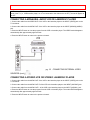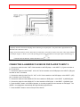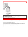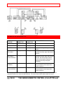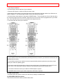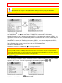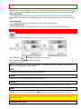
1
IMPORTANT
53SBX01
-1-
PROJECTION COLOR TV
OPERATING GUIDE
IMPORTANT
-2TABLE OF CONTENTS
IMPORTANT ..............................................................................................................................................................................3
ACCESSORIES...........................................................................................................................................................................8
FRONT PANEL JACKS AND CONNECTIONS.....................................................................................................................12
REAR PANEL JACKS..............................................................................................................................................................13
REAR PANEL JACKS..............................................................................................................................................................14
REAR SPEAKER TERMINAL CONNECTIONS....................................................................................................................15
TIPS ON REAR PANEL CONNECTIONS ..............................................................................................................................16
EXTERNAL AUDIO SOURCES..............................................................................................................................................17
CONNECTING EXTERNAL VIDEO SOURCES ...................................................................................................................17
AUDIO SYSTEM SET-UP .......................................................................................................................................................20
AUDIO SYSTEM SET-UP .......................................................................................................................................................21
PICTURE-IN-PICTURE (PIP) ..................................................................................................................................................26
USING THE REMOTE TO CONTROL VCR FUNCTIONS...................................................................................................30
USING THE REMOTE TO CONTROL CABLE BOX FUNCTIONS.....................................................................................30
USING THE REMOTE TO CONTROL SATELLITE RECEIVER FUNCTIONS..................................................................32
USING THE REMOTE TO CONTROL DVD FUNCTIONS ..................................................................................................32
USING THE REMOTE TO CONTROL ADDITIONAL AUDIO/VIDEO EQUIPMENT ......................................................34
CABLE/SATELLITE, VCR, AUDIO AND DVD CODES (CLU-573TSI and CLU-574TSI) ................................................35
VCR BRANDS ......................................................................................................................................................................35
DVD BRAND ........................................................................................................................................................................38
CABLE BRAND ...................................................................................................................................................................38
SATELLITE BRAND
CODES........................................................................................................................................40
AMPLIFIER BRAND............................................................................................................................................................40
CD BRAND ...........................................................................................................................................................................40
TAPE BRAND.......................................................................................................................................................................41
ULTRATEC BIT-MAP On Screen Display ..............................................................................................................................42
ULTRATEC OSD..................................................................................................................................................................42
SET UP ......................................................................................................................................................................................44
MENU LANGUAGE.............................................................................................................................................................44
PLUG & PLAY......................................................................................................................................................................44
SIGNAL SOURCE...............................................................................................................................................................45
AUTO CHANNEL SET .......................................................................................................................................................46
CHANNEL MEMORY .........................................................................................................................................................47
CHANNEL LIST ...................................................................................................................................................................48
CLOCK SET .........................................................................................................................................................................49
MAGIC FOCUS ...................................................................................................................................................................50
CHANNEL ID .......................................................................................................................................................................51
VIDEO ID..............................................................................................................................................................................52
FAMILY FAVORITES (MENU) ..........................................................................................................................................52
FAMILY FAVORITES (OPERATION) ..............................................................................................................................53
PARENTAL CONTROL ......................................................................................................................................................53
4 EVENT PROG. .................................................................................................................................................................54
AUTO LINK ..........................................................................................................................................................................56
CLOSED CAPTION..............................................................................................................................................................56
MENU BACKGROUND.......................................................................................................................................................57
FIRST TIME TOUR ..............................................................................................................................................................57
VIDEO .......................................................................................................................................................................................58
CONTRAST ..........................................................................................................................................................................58
BRIGHTNESS.......................................................................................................................................................................58
COLOR ..................................................................................................................................................................................58
TINT ......................................................................................................................................................................................59
SHARPNESS .........................................................................................................................................................................59
RESET ...................................................................................................................................................................................59
ADVANCED SETTINGS .....................................................................................................................................................59
AUDIO.......................................................................................................................................................................................60
BASS .....................................................................................................................................................................................60
TREBLE ................................................................................................................................................................................60
IMPORTANT
-3-
BALANCE.............................................................................................................................................................................60
RESET ...................................................................................................................................................................................60
ADVANCED SETTINGS .....................................................................................................................................................60
THEATER .................................................................................................................................................................................62
THEATER MODES ..............................................................................................................................................................62
SURROUND ........................................................................................................................................................................62
DOLBY PRO LOGIC ............................................................................................................................................................64
TEST TONE .........................................................................................................................................................................64
GRAPHIC EQUALIZER.......................................................................................................................................................65
WIRELESS SOUND ...........................................................................................................................................................66
MAIN TV AUDIO.................................................................................................................................................................66
PIP AUDIO............................................................................................................................................................................66
REAR SPEAKERS ................................................................................................................................................................66
SUB WOOFER ....................................................................................................................................................................66
INFO ..........................................................................................................................................................................................67
SPECIAL EVENT REMINDER ..........................................................................................................................................67
CALENDAR..........................................................................................................................................................................68
CARE OF YOUR HITACHI PROJECTION TV AND YOUR REMOTE CONTROL ...........................................................68
RECEPTION PROBLEMS........................................................................................................................................................69
USEFUL INFO ..........................................................................................................................................................................70
HITACHI SERVICE HOTLINE ...........................................................................................................................................72
NOTES.......................................................................................................................................................................................72
Back cover .................................................................................................................................................................................72
IMPORTANT
Follow all warnings and instructions marked on this projection television.
CAUTION: TO REDUCE THE RISK OF ELECTRIC SHOCK,
DO NOT REMOVE COVER (OR BACK).
NO USER SERVICEABLE PARTS INSIDE.
REFER SERVICING TO QUALIFIED SERVICE PERSONNEL.
The lightning flash with arrowhead symbol, within an equilateral triangle, is intended to alert the user to
the presence of uninsulated "dangerous voltage" within the product's enclosure that may be of sufficient
magnitude to constitute a risk of electric shock to persons.
The exclamation point within an equilateral triangle, is intended to alert the user to the presence of
important operating and maintenance (servicing) instructions in the literature accompanying the appliance.
WARNING:
TO PREVENT FIRE OR SHOCK HAZARD, DO NOT EXPOSE THIS COLOR TELEVISION TO RAIN OR
MOISTURE.
NOTE: • There are no user serviceable parts inside the television.
• Model and serial numbers are indicated on back side of the television.
• This television is not intended for use in a computer room.
CAUTION: Adjust only those controls that are covered in the instructions, as improper changes
or modifications not expressly approved by Hitachi could void the user's warranty.
CAUTION: TO PREVENT ELECTRIC SHOCK, MATCH WIDE BLADE OF PLUG TO WIDE SLOT, FULLY
INSERT.
IMPORTANT
-4-
MODIFICATIONS: The FCC requires the user to be notified that any changes or modifications made to
this device that are not expressly approved by Hitachi America, Ltd. Home Electronics Division may void
the user's warranty.
POWER SOURCE:
This projection television is designed to operate on 120 volts 60Hz, AC current.
Insert power cord into a 120 volt 60Hz outlet.
TO PREVENT ELECTRIC SHOCK, DO NOT USE THE TELEVISION'S (POLARIZED) PLUG WITH AN
EXTENSION CORD, RECEPTACLE, OR OTHER OUTLET UNLESS THE BLADES AND GROUND TERMINAL
CAN BE FULLY INSERTED TO PREVENT BLADE EXPOSURE.
NEVER CONNECT THE TV TO 50Hz, DIRECT CURRENT, OR ANYTHING OTHER THAN THE SPECIFIED
VOLTAGE.
NOTE: This television receiver will display television closed captioning (
paragraph 15.119 of the FCC rules.
or
), in accordance with
CAUTION: Never remove the back cover of the television as this can expose you to very high voltages and other
hazards. If the television does not operate properly, unplug the television and call your authorized dealer or service shop. pg.
3 SAFETY TIPS
IMPORTANT SAFEGUARDS
SAFETY POINTS YOU SHOULD KNOW ABOUT
YOUR HITACHI PROJECTION TELEVISION
CAUTION:
• Read all of these instructions.
• Save these instructions for later use.
• Follow all warnings and instructions marked on the television.
Our reputation has been built on the quality, performance, and ease of service of HITACHI televisions.
Safety is also foremost in our minds in the design of these units. To help you operate these products properly, this
section illustrates safety tips which will be of benefit to you. Please read it carefully and apply the knowledge you
obtain from it to the proper operation of your HITACHI television.
Please fill out your warranty card and mail it to HITACHI. This will enable HITACHI to notify you promptly in the
improbable event that a safety problem should be discovered in your product model.
FOR YOUR PERSONAL SAFETY
1 This television set is equipped with a polarized alternating-current line plug (a plug having one blade wider than
the other). This plug will fit into the power outlet only one way. This is a safety feature. If you are unable to insert
the plug fully into the outlet, try reversing the plug. If the plug should still fail to fit, contact your electrician to
replace your obsolete outlet. Do not defeat the safety purpose of the polarized plug.
2 When the power cord or plug is damaged or frayed, unplug this television set from the wall outlet and refer
servicing to qualified service personnel.
3 Do not overload wall outlets and extension cords as this can result in fire or electric shock.
IMPORTANT
-5-
4 Do not allow anything to rest on or roll over the power cord, and do not place the television where the power
cord is subject to traffic or abuse. This may result in a shock or fire hazard.
5 Do not attempt to service this television yourself as opening or removing covers may expose you to dangerous
voltage or other hazards. Refer all servicing to qualified service personnel.
6 Never push objects of any kind into this television set through the television cabinet's slots as they may touch
dangerous voltage points or short out parts that could result in a fire or electric shock. Never spill liquid of any kind
on the television.
7 If the television has been dropped or the cabinet has been damaged, unplug this television from the wall outlet
and refer servicing to qualified service personnel.
8 If liquid has been spilled into this television set, unplug it from the wall outlet and refer service to qualified
service personnel.
9 Do not subject your television to impact of any kind. Be careful not to damage the picture tube surface.
10 Unplug this television from the wall outlet before cleaning. Use a damp cloth for cleaning. Do not use liquid or
aerosol cleaners.
11-1 Do not place this television on an unstable cart, stand, or table. The television may fall, causing serious
injury to a child or an adult, and serious damage to the appliance. Use only with a cart or stand recommended by
the manufacturer, or sold with the television. Wall or shelf mounting should follow the Wall/Shelf mounting
manufacturer's instructions, and should use a mounting kit approved by the manufacturer.
11-2 An appliance and cart combination should be moved with care. Quick stops, excessive force, and uneven
surfaces may cause the appliance and cart combination to overturn.
PROTECTION AND LOCATION OF YOUR TELEVISION
12 Do not use the television near water, for example, near a bathtub, washbowl, kitchen sink, or laundry tub, in a wet
basement, or near a swimming pool, etc.
• Never expose the television to rain or water. If the set has been exposed to rain or water, unplug television from wall outlet
IMPORTANT
-6-
and refer to qualified service personnel.
13 Choose a place where light (artificial or sunlight) does not shine directly on the screen.
14 Avoid dusty places. Accumulated dust inside the chassis may cause failure of the television when high humidity persists.
15 The television has slots, or openings in the cabinet for ventilation purposes which provide reliable operation of the
receiver and protect the television from overheating. These openings must not be blocked or covered.
• Never cover the slots or openings with cloth or other material.
• Never block the bottom ventilation slots of the set by placing it on a bed, sofa, rug, etc.
• Never place the set near or over a radiator or heat generator.
• Never place the television in a built-in enclosure unless proper ventilation provided.
pg. 4 SAFETY TIPS (cont.)
PROTECTION AND LOCATION OF YOUR TELEVISION
16-1 If an outside antenna is connected to the television , be sure the antenna system is grounded so as to
provide some protection against voltage surges and built up static charges. Section 810 of the National Electrical
Code, NFPA No. 70-1975, provides information with respect to proper grounding of the mast and supporting
structure, grounding of the lead-in wire to an antenna discharge unit, size of grounding conductors, location of
antenna discharge unit connection to grounding electrode, and requirements for the grounding electrode.
EXAMPLE OF ANTENNA GROUNDING AS PER NATIONAL ELECTRICAL CODE INSTRUCTIONS.
16-2 Note to CATV system installer: (Only for television with CATV reception) This reminder is provided to call
the CATV system installer's attention to Article 820-40 of the NEC that provides guidelines for proper grounding
and, in particular, specifies that the cable ground shall be connected to the grounding system of the building, as
close to the point of cable entry as practical.
17 An outside antenna system should not be located in the vicinity of overhead power lines or other electrical
lights or power circuits, or where it can fall into such power lines or circuits. When installing an outside antenna
system, extreme care should be taken to keep from touching such power lines or circuits as contact with them
might be fatal.
18 For added protection for the television during a lightning storm, or when it is unused for long periods of time,
unplug it from the wall outlet and disconnect antenna. This will prevent damage due to lightning and power-line
surges.
IMPORTANT
-7-
OPERATION OF YOUR TELEVISION
19 This television should be operated only from the type of power source indicated on the marking label. If you
are not sure of the type of power supply at your home, consult your dealer or local power company. For
televisions designed to operate from battery power, refer to the operating instructions.
20 If the television does not operate normally by following the operating instructions, unplug the television from
the wall outlet and refer servicing to qualified service personnel. Adjust only those controls that are covered in the
instructions as improper adjustment of other controls may result in damage and will often require extensive work
by a qualified service technician to restore the television to normal operation.
21 If your television is to remain unused for a period of time, (such as when going on a holiday), turn the television
OFF and unplug it from the wall outlet.
IF THIS TELEVISION DOES NOT OPERATE PROPERLY
22 If you are unable to restore normal operation by following the detailed procedure in your operating instructions,
do not attempt any further adjustment. Unplug the television and call your dealer or service technician.
23 Whenever the television is damaged or fails, or if there is a distinct change in performance that indicates a
need for service, unplug the television and have it checked by a qualified service technician.
24 It is normal for some televisions to make occasional snapping or popping sounds, particularly when being
turned on or off. If the snapping or popping is continuous or frequent, unplug the set and consult your dealer or
service technician.
FOR SERVICING AND MODIFICATION
25 Do not use attachments not recommended by the television manufacturer as they may cause hazards.
26 If replacement parts are required, be sure the service technician has used replacement parts specified by the
manufacturer that have the same characteristics as the original part. Unauthorized substitutions may result in fire,
electric shock, or other hazards.
ACCESSORIES
-8-
screen or a "PATTERN BURN" may develop over a long period of time.
Public Viewing of Copyrighted Material
Public viewing of programs broadcast by TV stations and cable companies, as well as programs from other
sources, may require prior authorization from the broadcaster or owner of the video program material.
ACCESSORIES
Check to make sure that you have the following accessories before disposing of the packing material.
CLU-573TSI
CLU-574TSI
1. Remote Control Unit CLU-573TSI ( Part No. HL01323) or CLU 574TSI (Part No. HL01324).
2. Two "AA" size, 1.5V batteries (For Remote Control Unit).pg. 5 (cont.)
REMOTE
CONTROL BATTERY INSTALLATION AND REPLACEMENT
1. Open the battery cover of the remote control by pushing the notched part of the cover with your fingers and
pulling the cover off.
2. Insert two new "AA" size batteries for the remote control. When replacing old batteries, push them towards the
springs and lift them out.
3. Match the batteries to the (+) and (-) marks in the battery compartment.
4. Replace the cover.
BOTTOM VIEW
ACCESSORIES
-9-
pg. 6
HOW TO SET UP YOUR NEW HITACHI PROJECTION
TV
ANTENNA
Unless your TV is connected to a cable TV system or to a centralized antenna system, a good outdoor color TV
antenna is recommended for the best performance. However, if you are located in an exceptionally good signal
area that is free from interference and multiple image ghosts, an indoor antenna may be sufficient.
LOCATION
Select an area where sunlight or bright indoor illumination will not fall directly on the picture screen. Also, be sure
that the location selected allows a free flow of air to and from the perforated back cover of the set.
To avoid cabinet warping, cabinet color changes, and increased chance of set failure, do not place the TV where
temperatures can become excessively hot, for example, in direct sunlight or near a heating appliance, etc.
VIEWING
The major benefit of the HITACHI Projection Television is its large viewing screen. To see this large screen at its
best, test various locations in the room to find the optimum spot for viewing.
The best picture is seen by sitting directly in front of the TV and about 10 to 18 feet from the screen. Picture
brightness decreases as the viewer moves to the left and right of the receiver.
During daylight hours, reflections from outside light may appear on the screen. If so, drapes or screens can be
used to reduce the reflection or the TV can be located in a different section of the room.
If the TV's audio output will be connected to a Hi-Fi system's external speakers, the best audio performance will
be obtained by placing the speakers equidistant from each side of the receiver cabinet and as close as possible to
the height of the picture screen center. For best stereo separation, place the external speakers at least four feet
from the side of the TV, place the surround speakers to the side or behind the viewing area. Differences in room
sizes and acoustical environments will require some experimentation with speaker placement for best
performance.
CAUTION: Magnetic fields, such as those of external speakers, may cause the picture to distort if they are placed
too close to the television. Move the magnetic field source away from the television until there is no picture distortion.pg. 7
ACCESSORIES
- 10 -
HOOK-UP CABLES AND CONNECTORS
Most video/audio connections between components can be made with shielded video and audio cables that have
phono connectors. For best performance, video cables should use 75-Ohm coaxial shielded wire. Cables can be
purchased from most stores that sell audio/video products. Below are illustrations and names of common
connectors. Before purchasing any cables, be sure of the output and input connector types required by the
various components and the length of each cable.
300-Ohm Twin Lead Connector
This outdoor antenna cable must be connected to an
antenna adaptor (300-Ohm to 75-Ohm).
"F" Type 75-Ohm Coaxial Antenna Connector
For connecting RF signals (antenna or cable TV) to the
antenna jack on the television.
Phono Connector
Used on all standard video and audio cables which
connect to inputs and outputs located on the television's
rear jack panel and front control panel.
S-Video (Super Video) Connector
This connector is used on camcorders, VCRs, and
laserdisc players with an S-Video feature in place of the
standard video cable to produce a high-quality picture.
ANTENNA CONNECTIONS TO REAR JACK PANEL
VHF (75-Ohm) antenna/CATV (Cable TV)
When using a 75-Ohm coaxial cable system, connect the outdoor antenna or CATV coaxial cable to the ANT A
(75-Ohm) terminal. If you have a second antenna or cable TV system, connect the coaxial cable to the ANT B
terminal.
To outdoor antenna or CATV cable
VHF (300-Ohm) antenna/UHF antenna
When using a 300-Ohm twin lead from an outdoor antenna. connect the VHF or UHF antenna leads to screws of
the VHF or UHF adaptor. Plug the adapter into the antenna terminal on the TV.
To outdoor VHF or UHF Antenna
When both VHF and UHF antennas are connected
Attach an optional antenna cable mixer to the TV antenna terminal, and connect the cables to the antenna mixer.
Consult your dealer or service store for the antenna mixer.
ACCESSORIES
- 11 -
pg. 8
FRONT PANEL CONTROLS
FRONT VIEW
MENU Button
This button allows you to enter the MENU, making it possible to set TV features to your preference without using
the remote.
INPUT/EXIT button
Press this button to select the current antenna source, VIDEO: 1, 2, 3, or alternate antenna source. Your
selection is shown in the top right corner of the screen. This button also serves as the EXIT button when in
MENU mode.
CHANNEL Selector
Press these buttons until the desired channel appears at the top right corner of the TV screen. These buttons also
serve as the cursor down (
) and up ( ) buttons when in MENU mode.
VOLUME Level
Press these buttons for your desired sound level. The volume level will be displayed on the TV screen. These
buttons also serve as the cursor left (
) and right (
) buttons when in MENU mode.
FRONT PANEL JACKS AND CONNECTIONS
- 12 -
POWER Button
Press this button to turn the TV on or off.
NOTES:
Your HITACHI Projection TV will appear to be turned OFF if there is no video input when VIDEO: 1, 2 or 3 is selected.
Check the Power Light to make sure the TV is turned off when not in use.
To see an auto-demonstration of the on-screen displays with HELP text displayed, press and hold the POWER button on the
TV set for approximately five seconds. Press the POWER button on the TV again to end the auto-demonstration.pg. 9
FRONT PANEL CONTROLS (CONT.)
POWER light
You will see a red light when the TV is turned on.
AI (Artificial Intelligence) sensor
The artificial Intelligence sensor will make automatic picture adjustments depending on the amount of light in the
room to give the best picture. (See page 55.)
REMOTE CONTROL Sensor
Point your remote control at this area when selecting channels, adjusting volume, etc.
MAGIC FOCUS
Use this button to adjust your picture quality to optimum performance. (See page 44.)
FRONT INPUT JACKS (for VIDEO: 3)
Use these audio/video jacks for a quick hook-up from a camcorder or VCR to instantly view your favorite show or
new recording. Press the INPUT button until VIDEO: 3 appears in the top right corner of the TV screen. If you
have mono sound, insert the audio cable into the left audio jack.
FRONT PANEL JACKS AND CONNECTIONS
The front panel jacks are provided as a convenience to allow you to easily connect a camcorder or VCR as shown
in the following examples.
REAR PANEL JACKS
- 13 -
NOTE:
Completely insert connection cord plugs when connecting to front panel jacks. If you do not, the played back
picture may be abnormal. If you have a S-VHS VCR, use the S-INPUT cable in place of the standard video
cable. If you have a mono VCR, insert the audio cable into the left channel jack of your TV.
REAR PANEL JACKS
Antenna Input/Output
The remote control allows you to switch between two separate 75-Ohm RF antenna inputs, ANT A and ANT B.
ANT A input can be displayed as a main picture or sub-picture. ANT B can only be displayed as a main picture.
(ANT B cannot be displayed as a sub-picture.) The antenna output labeled "TO CONVERTER" allows the ANT A
connection to pass directly to a different source such as a cable box, when ANT B is displayed as a main picture.
Audio/Video Inputs 1and 2
The INPUT button will step through each video source and antenna source input each time it is pressed. Use the
audio and video inputs to connect external devices, such as VCRs, camcorders, laserdisc players, DVD players,
etc. (If you have mono sound, insert the audio cable into the left channel jack).
NOTE: You may use VIDEO, S-VIDEO, or COMPONENT VIDEO: Y-CB-CR inputs to connect to INPUT 2, but
note that only one of these may be used at a time.
Monitor Out
These jacks provide fixed audio and video signals which are used for recording.To have S-VIDEO , S-VIDEO
signal needs to be input to INPUT 1 or INPUT 2, or INPUT 3.
(4) WIRELESS OUT
These jacks provide variable audio output to a set of wireless speakers. They can also be used for another
stereo system amplifier. With this connection, the audio can be controlled by the television's main volume and
also by an independent volume feature found in the THEATER-WIRELESS SOUND menu.
(5) AUDIO TO HI-FI
REAR PANEL JACKS
- 14 -
These jacks provide variable audio output to a separate stereo amplifier. With this connection, the audio to the
stereo can be controlled by the television's main volume. Use these jacks for the SURROUND Left and Right
channels. (see page 20)
(6) REAR SPEAKER Terminals
These terminals are used to connect external speaker, which are used for the surround sound feature. The volume level is
controlled by the television's main volume and also by an independent rear volume feature found in the THEATERSURROUND menu. Use speaker with 8-Ohm impedance only.pg. 12 REAR PANEL JACKS
(7) S-VIDEO INPUTS 1 and 2
Inputs 1 and 2 provide S-Video (Super Video) jacks for connecting equipment with S-VIDEO output capability.
(8) Component: Y-CB-CR INPUT 2
INPUT 2 provides Y-CB-CR jacks for connecting equipment with this capability, such as a DVD.
NOTES:
DO NOT connect standard VIDEO or S-VIDEO to INPUT 2 when using Y-CB-CR input.
When using the Y-CB-CR input jacks, connect your components audio output to the TV's INPUT 2 Left and Right
Audio input jacks.
Your component outputs may be labeled Y, B-Y, and R-Y. In this case, connect the components B-Y output to
the TV's CB input and the components R-Y output to the TV's CR input.
It may be necessary to adjust TINT to obtain optimum picture quality when using the Y-CB-CR inputs. (See
pages 54 and 55.)
To ensure no copyright infringement, the MONITOR OUT output will be abnormal, when using the Y-CB-CR
jacks.
When using the Y-CB-CR jacks, INPUT 2 will be viewed as a blank PIP sub-picture. (see page 26)
(9) SUB WOOFER
This jack provides variable audio output to a sub-woofer accessory. With this connection, the audio can be
controlled by the television's main volume and also by an independent sub-woofer feature found in the THEATERSUB WOOFER menu.
REAR PANEL JACKS
REAR SPEAKER TERMINAL CONNECTIONS
- 15 -
Typical full feature setup. Follow connections that pertain to your personal entertainment
system.
REAR SPEAKER TERMINAL CONNECTIONS
CONNECT AFTER TURNING THE POWER TO THE TV OFF.
TIPS ON REAR PANEL CONNECTIONS
- 16 -
Press the Right Speaker red button and insert the positive (+) lead wire into the hole next to the button. Once the
wire is in place, pull the red button back to original position and the wire is locked into place. In the same manner,
press the Right Speaker black button and insert the negative (-) lead wire. Repeat this procedure for the Left
Speaker.
CAUTION: Do not short speaker terminal, (do not connect a wire directly across any two terminals). This
could cause damage to your audio outputs or other damage to your TV.
CAUTION: Do not connect speakers simultaneously to the REAR SPEAKER terminal of the Projection
TV and an external amplifier. This could damage both the TV and the speakers. Your TV was designed to use 8Ohm speakers only. Any other type may degrade the audio performance of your entertainment system..
TIPS ON REAR PANEL CONNECTIONS
TIPS ON REAR PANEL CONNECTIONS
S-Video connections are provided for high performance laserdisc players, VCRs etc., that have this feature. Use
these connections in place of the standard video connection if your device has this feature.
If your device has only one audio output (mono sound), connect it to the left audio jack on the TV.
Refer to the operating guide of your other electronic equipment for additional information on connecting your
hook-up cables.
A single VCR can be used for VCR #1 and VCR #2, but note that a VCR cannot record its own video or line
output. (INPUT 1 in example on page 13.) Refer to your VCR operating guide for more information on line inputoutput connection.
You may use VIDEO, S-VIDEO, or COMPONENT VIDEO: Y-CB-CR inputs to connect to INPUT 2, but only one
of these may be used at a time.
Connect only 1 component to each input jack.
COMPONENT VIDEO: Y-CB-CR connections are provided for high performance components, such as DVD
players. Use these connections in place of the standard video connection if your device has this feature.
When using the Y-CB-CR input jacks, connect your components audio output to the TV's INPUT 2 Left and Right
Audio input jacks.
Your component outputs may be labeled Y, B-Y, and R-Y. In this case, connect the components B-Y output to the
TV's CB input and the components R-Y output to the TV's CR input.
EXTERNAL AUDIO SOURCES
- 17 -
It may be necessary to adjust TINT to obtain optimum picture quality when using the Y-CB-CR inputs. (See pages
54 and 55.)
To ensure no copyright infringement, the MONITOR OUT output will be abnormal, when using Y-CB-CR jacks.
When using the Y-CB-CR jacks, INPUT 2 will be viewed as a blank PIP sub-picture. (see page 26)
EXTERNAL AUDIO SOURCES
CONNECTING EXTERNAL AUDIO AMPLIFIER
NOTES: To prevent damage to the speaker and distorted sound, set the volume control of the audio amplifier
lower and adjust the sound using the remote control fo the TV set.
Do not connect speakers simultaneously to the REAR SPEAKER terminal of the Projection TV and an external
amplifier.
CONNECTING EXTERNAL VIDEO SOURCES
The exact arrangement you use to connect the VCR, camcorder, laserdisc player, DVD player or HDTV Set Top
Box to your TV set is dependent on the model and features of each component. Check the owner's manual of
each component for the location of video and audio inputs and outputs.
The following connection diagrams are offered as suggestions. However, you may need to modify them to
accommodate your particular assortment of components and features. For best performance, video and audio
cables should be made from coaxial shielded wire.
Before Operating External Video Source
The input mode is changed every time the INPUT button is pressed as shown below. Connect an external source
to the INPUT terminal, then press the INPUT button as necessary to view the input source. (See page 24.)
INPUT MODE SELECTION ORDER
CONNECTING EXTERNAL VIDEO SOURCES
- 18 -
NOTE: When TV is set to VIDEO and a video signal is not received from the VIDEO INPUT jack on the jack
panel of the TV (i.e., VCR/laserdisc player, etc. is not connected or the video device is OFF), the set will appear to
be OFF.
CONNECTING A MONAURAL AUDIO VCR OR LASERDISC PLAYER
1. Connect the cable from the VIDEO OUT of the VCR or the laserdisc player to the INPUT (VIDEO) jack on the
TV set below.
2. Connect the cable from the AUDIO OUT of the VCR or the laserdisc player to the INPUT (MONO)/L(AUDIO)
jack.
3. Press the INPUT button to view the program from the VCR or laserdisc player. The VIDEO mode disappears
automatically after approximately eight seconds.
4. Press the INPUT button to return to the previous channel.
pg. 18
CONNECTING EXTERNAL VIDEO
SOURCES (cont.)
CONNECTING A STEREO VCR OR STEREO LASERDISC PLAYER
1. Connect the cable from the AUDIO OUT of the VCR or the laserdisc player to the INPUT (VIDEO) jack on the
TV set below.
2. Connect the cable from the AUDIO OUT R of the VCR or the laserdisc player to the INPUT (AUDIO/R) jack.
3. Connect the cable from the AUDIO OUT L of the VCR or the laserdisc player to the INPUT (AUDIO/L) jack.
4. Press the INPUT button to view the program from the VCR or laserdisc player. The mode VIDEO disappears
automatically after approximately eight seconds.
5. Press the INPUT button to return to the previous channel.
CONNECTING EXTERNAL VIDEO SOURCES
- 19 -
NOTES:
Completely insert the connection cord plugs when connecting to rear panel jacks. The picture that is played back will be
abnormal if the connection is loose.
A single VCR can be used for VCR #1 and VCR #2, but note that a VCR cannot record its own video or line output. (INPUT
1 in example on page 13) Refer to your VCR operating guide for more information on line input-output connections.pg. 19
CONNECTING EXTERNAL VIDEO SOURCES (cont.)
CONNECTING A LASERDISC PLAYER OR DVD PLAYER TO INPUT 2.
1. Connect the cable from the Y OUT of the Laserdisc or the DVD player to the INPUT 2 (Y) jack as shown on
the TV set below.
2. Connect the cable from the CB OUT or B-Y OUT of the Laserdisc or the DVD player to the INPUT 2 (CB) jack,
as shown on the TV set below.
3. Connect the cable from the CR or R-Y OUT or B-Y of the Laserdisc or the DVD player to the INPUT 2 (CR)
jack, as shown on the TV set below.
4. Connect the cable from the AUDIO OUT R of the Laserdisc or DVD player to the INPUT 2 (AUDIO/R) jack.
5. Connect the cable from the AUDIO OUT L of the Laserdisc or DVD player to the INPUT 2 (AUDIO/L) jack.
6. Press the INPUT button until VIDEO:2 appears, to view the program from the Laserdisc or DVD player. The
VIDEO:2 icon disappears automatically after approximately eight seconds.
7. Press the INPUT button to return to the previous channel.
AUDIO SYSTEM SET-UP
- 20 -
NOTES:
Completely insert the connection cord plugs when connecting to rear panel jacks. The picture that is played back
will be abnormal if the connection is loose.
See Page 15 for tips on REAR PANEL CONNECTIONS.
AUDIO SYSTEM SET-UP
Match the numbers below to the diagrams for speaker placement and refer to the table on page 21 for the
different surround sound requirements. (See page 59 for SURROUND functions.)
The television's internal speakers.
The television's internal center channel speakers, which are on only when the television is in SURROUNDPRO LOGIC, or SURROUND-DOLBY 3 STEREO mode.
(3) These speakers are connected to a separate audio amplifier. Use the AUDIO TO HI-FI output on the TV.
(4) These speakers are connected to the rear speaker 8 Ohm output on the TV.
(5) These speakers are controlled by a wireless speaker transmitter. Use the WIRELESS OUT output on the TV.
(6) This sub woofer is connected to the SUB WOOFER output on the TV.
AUDIO SYSTEM SET-UP
- 21 -
AUDIO SYSTEM SET-UP
SURROUND
FEATURE
REQUIRED
CONNECTION
OPTIONAL
CONNECTION
(1)
(3) (5) (6)
Receive mono and stereo sound.
(1) (4)
(3) (5) (6)
Gives the listener concert hall sound.
(1) (4)
(3) (5) (6)
Listener has feeling of being at a
stadium.
DOLBY
PRO LOGIC
(1) (2) (4)
(3) (5) (6)
Movie theater reproduction, with
separate left, center, right, and surround
speakers.
DOLBY
PRO LOGIC*
(TV AS CENTER)
(2) (3) (4)
(5) (6)
Movie theater reproduction, with
separate left, center, right, and surround
channels, with left and right channels
added to audio amplifier speakers to
improve sound clarity and spatial
positioning.
DOLBY 3 STEREO (1) (2)
(NORMAL)
(3) (5) (6)
Movie theater reproductions, surround
channel added to left and right audio
amplifier speakers.
DOLBY 3 STEREO (2) (3)
(TV AS CENTER)
(5) (6)
Movie theater reproduction, surround
channel added to left and right audio
amplifier speakers.
OFF
HALL
MATRIX
EFFECT
Left and right speakers are connected ( (3) ), and the internal speakers ( (1) ) can be disabled, creating better
separation between left, center and right channels. The center channel audio will be heard from ( (2) ).
pg. 22-34
THE GENIUS REMOTE CONTROL (CLU-573TSI and
AUDIO SYSTEM SET-UP
- 22 -
CLU-574TSI)
In addition to controlling all the functions on your HITACHI Projection TV, the new remote is designed to operate
different types of VCRs, CATV (Cable TV) converters, satellite receivers, DVD players, and other audio/video
equipment with one touch. Basic operation keys are grouped together in one area.
To operate your TV, point the remote control at the remote sensor of the TV and press the TV button. The TV
button will blink, indicating that the remote will now control your television.
To operate your VCR, point the remote at the remote sensor of the VCR and press the VCR button. The VCR
button will blink, indicating that the remote will now control your VCR. (See page 29 for instructions on how to
program the remote to control your VCR.)
To operate your cable box, point the remote at the remote sensor of the cable box and press the CABLE (CBL)
button. The CBL button will blink, indicating that the remote will now control your cable box. (See page 30 for
instructions on how to program the remote to control your cable box.)
To operate your satellite receiver, point the remote at the remote sensor of the satellite receiver and press the
SATELLITE (SAT) button. The SAT button will blink, indicating that the remote will now control your satellite
receiver. (See page 31 for instructions on how to program the remote to control your satellite receiver.)
To operate your DVD player, point the remote at the remote sensor of the DVD player and press the DVD button.
The DVD button will blink, indicating that the remote will now control your DVD player. (See page 32 for
instruction on how to program the remote to control your DVD player.)
To operate additional audio/video equipment, point the remote at the remote sensor of the component and press
the AV1, AV2 or AV3 button. This button will blink, indicating that the remote will now control the desired
component. (See page 33 for instructions on how to program the remote to control additional audio/video
equipment.)
AUDIO SYSTEM SET-UP
- 23 -
(1)These buttons allow
the remote to control
your TV, VCR, cable
box, satellite receiver,
DVD player, or other
audio/video equipment
depending on which
mode is chosen, as
explained above.
(2), (3) LIGHT BUTTON
When you are in a dark
room, press the light
button (2) on the side of
the remote to light up the
buttons shown in (3) and
the source button will
blink . The light will stay
on for about 8 seconds if
the light button is not
pressed again. These
buttons will not appear
to light if the room is too
bright.
Click here for CLU-573TSI.
Click here for CLU-574TSI.
(1) POWER Button
Press this button to turn the TV set on or off when the remote is in TV mode. (See page 22 for instructions on
how to set the remote control to TV mode.) If a SPECIAL EVENT REMINDER is set, it will be displayed when the
TV is first turned on. (see page 64)
(2) TV button
When the TV button is pressed, it will blink, to indicate the remote is in TV mode.
(3) VCR button
When the VCR button is pressed, it will blink to indicate the remote is in VCR mode. (See page 29)
AUDIO SYSTEM SET-UP
- 24 -
(4) CABLE button
When the CABLE button is pressed, it will blink to indicate the remote is in CABLE mode. (See page 30)
(5) SAT button
When the SAT button is pressed, it will blink, to indicate the remote is in satellite mode. (See page 31)
(6) DVD button
When the DVD button is pressed, it will blink, to indicate the remote is in DVD mode. (See page 32)
(7) AV1, AV2, AV3 buttons
When pressed, each of these buttons will blink to indicate the remote is in Audio/Video mode.
(19) VOLUME, MUTE button
Press the VOLUME up ( ) or down (
) button until you obtain the desired sound level.
To reduce the sound to one half of normal volume (SOFT MUTE) to answer the telephone, etc., press the MUTE
button. Press the MUTE button again to turn the sound off completely (MUTE). To restore the sound, press the
MUTE button one more time, or press the VOLUME up ( ) button.
(9) CHANNEL selector buttons
CHANNEL selector buttons are used to set FAMILY FAVORITES, CHANNEL MEMORY, etc.
Enter one, two or three numbers to select channels. Enter "0" first for channels 1 to 9. For channels 100 and
above, press the "1" button, wait until two dashes appears next to the channel display on your TV, then enter the
remaining two numbers using the number buttons.
).
Channel selection may also be performed by pressing CH up ( ) or down (
NOTE: The TV may not receive some channels if you are not in the correct SIGNAL SOURCE mode. (See page
39.)
(10) SLEEP button
Press this button to display the sleep timer in the lower left corner of the screen. Every subsequent press of this
button will add 15 minutes to this timer, up to a maximum of three hours. Once set, use RECALL when you want
to view time remaining. If the SLEEP button is pressed while the timer is set, it will reset to the original condition.
(11) LAST CHANNEL (LAST CH) button
Use this button to select between the last two channels viewed. (Good for watching two sporting events, etc.)
(12) INPUT button
The INPUT button will select between antenna signal and the three sets of video input jacks each time the button
is pressed. If the Picture-in-Picture is on, the INPUT button will select between the three sets of video input jacks
and both antenna sources when main channel is chosen with the PIP CH button. If the sub-picture is chosen, the
INPUT button will select between the three sets of video input jacks and the ANT A source (ANT B source cannot
be displayed as a PIP sub-picture and COMPONENT VIDEO: Y-CB-CR INPUT 2 source will be displayed as a
blank PIP Sub picture.)
AUDIO SYSTEM SET-UP
- 25 -
(13) HELP button
Press this button when a menu is displayed to view HELP text, which gives a description of the displayed menu. The HELP
text will be displayed every time a MENU is displayed, until this button is pressed again.
(14) COMMERCIAL SKIP (S.C.) button
Press the this button repeatedly to select channel skip time (30-180 seconds) when no menu is displayed and the TV will tune
to the last channel viewed when the selected amount of time is up. The user can change stations "SURF" to any station they
wish, and after the selected amount of time, the TV will tune back to the original channel.
(15) MENU button and THUMB STICK
All the On-Screen display features can be set or adjusted by using these buttons.
The MENU button will start the On-Screen Display.
The THUMB STICK will highlight functions or adjust and set different features. Press the THUMB STICK toward desired
direction and press down to select.
(16) EXIT button
When in MENU mode, this button will exit all On-Screen Displays.
(17) RECALL button
Press this button when no menu is displayed, when you want to check the channel being received, the picture source, or if
the channel has stereo (ST) or second audio (SAP), the time, CHANNEL ID, if the Commercial Skip (C.S.) is activated , if
SPECIAL EVENT REMINDER is set , and if the SLEEP timer is set.
PICTURE-IN-PICTURE (PIP)
- 26 -
When an S-VIDEO
Input is connected to
VIDEO: 1.
When an COMPONENT
VIDEO: Y-CB-CR Input
is connected to
VIDEO: 2.
(18) PICTURE-IN-PICTURE buttons
See separate section on page 26 for a description.
(19) PIP CH buttons
Use the PIP CH button to select between main picture and sub-picture and sub-picture tuning. The channel number which is
highlighted indicates what channel is being controlled.
(20) These buttons are not used on Remote Control CLU-574TSI.
PICTURE-IN-PICTURE (PIP)
Your HITACHI Projection TV incorporates Dual Tuner technology designed for improved viewing enjoyment. This
Dual Tuner feature allows you to view antenna inputs on both the main picture and sub-picture simultaneously,
with separate tuning control for each. The Dual Tuner can operate with only one input (ANT A only) or two inputs
(ANT A and ANT B).
ANT A input can be viewed as both the main picture and the sub-picture simultaneously. ANT B and
COMPONENT VIDEO: Y:CB-CR INPUT 2 sources can only be viewed as a main picture. To select between
main picture and PIP sub-picture tuning, press the PIP CH button on the remote. The highlighted channel display
will move with every press of the PIP CH button. When the top channel display is highlighted, channel tuning is
for the main picture. When the lower channel display is highlighted, channel tuning is for the PIP sub-picture.
This method of picture tuning is the same for one antenna input (ANT A only) and two antenna inputs (ANT A and
ANT B).
The Picture-in-Picture feature is convenient when you want to watch more than one program at the same time.
You can watch a TV program while viewing other programs from the ANT A source or any of the video inputs.
PICTURE-IN-PICTURE (PIP)
- 27 -
(1) PIP button
Press the PIP button and a sub-picture will appear in one of the three different modes (SINGLE, SPLIT or SURF),
or
depending on the last selection of the PIP mode. To change the PIP mode use the THUMB STICK
and the new selection will appear the next time the PIP function is used.
SINGLE MODE PIP
Press the PIP button and a sub-picture appears in one corner of the screen. Press the button again to reduce the
size of the sub-picture. Use the PIP button a third time to remove the sub-picture from the screen. Press the
INPUT button when sub-picture channel tuning is controlled, to change between VIDEO: 1, VIDEO: 2, VIDEO: 3
and ANT A antenna source. (ANT B source cannot be viewed as a sub-picture and COMPONENT VIDEO: Y-CBCR INPUT 2 source will be displayed as a blank sub-picture).
SPLIT MODE PIP
When you press the "PIP" button, the main channel and the PIP sub-picture will appear at the center of the
screen (main channel on left side and sub-picture on right side). Press the "PIP" button a second time to return t
normal viewing. Use the PIP CH button to select between man and sub-picture tuning control (indicated by
highlighted channel display). Press the INPUT button when sub-picture channel tuning is being controlled, to
change between VIDEO: 1, VIDEO: 2, VIDEO: 3, and ANT A antenna source. (ANT B source cannot be viewed
as a sub-picture and COMPONENT VIDEO: Y-CB-CR INPUT 2 source will be displayed as a blank sub-picture).
NOTES:
1. Since ANT B source cannot be viewed as a sub-picture, only SPLIT mode PIP is possible when ANT B is selected as the
main channel.
2. When ANT B is selected as a main channel, the SWAP feature is disabled.
3. When the COMPONENT VIDEO: Y-CB-CR INPUT 2 is selected as PIP, it will appear as a blank sub-picture.
4. When tuned to VIDEO:2 with COMPONENT VIDEO: (Y-CB-CR) you will not be able to access the PIP functions.
5. Only sound from main picture can be heard, unless you choose sub-picture audio from the THEATER-WIRELESS SOUND
mode and use the WIRELESS OUT outputs on the rear panel.
PICTURE-IN-PICTURE CONT.
PICTURE-IN-PICTURE (PIP)
- 28 -
SURF MODE PIP
This feature will automatically scan all active channel number (those set in memory) and display them as PIP subpictures, along the right edge of the screen. Press the PIP button a second time to remove the sub-pictures form
the screen.
NOTES:
1. If no buttons are pressed when in SURF mode, auto-scanning will continuously scan channels in memory.
2. If a channel is tuned during this SURF scanning, sub-pictures will be removed from the screen.
3. SURF mode PIP is allowed only when ANT A is selected as the main channel.
4. If PARENTAL CONTROL MOVIE/TV RATINGS setting is ON, PIP SURF mode will be deactivated.
(2) SWAP Button
If you wish to switch what is being shown on the main picture to the sub-picture, press the SWAP button.
NOTES:
1. The SWAP button will only operate when SINGLE PIP mode or SPLIT PIP mode is chosen.
2. The SWAP function will not operate if ANT B input is set as the main channel (ANT B input cannot be displayed
as a sub-picture.
(3) MOVE button
To move the sub-picture to another corner, press the MOVE button. The sub-picture moves one step
counterclockwise every time the MOVE button is pressed. (Example below illustrates the MOVE operation for
initial shipping conditions. If you have customized a PIP position, the MOVE operation may differ slightly from this
example.)
PICTURE-IN-PICTURE (PIP)
- 29 -
(4) FREEZE button (With PIP ON)
If you wish to freeze the sub-picture, press the FREEZE button. This is convenient when trying to write down the
address for a mail order company, recording statistics for a sporting event, etc. To return the picture to motion,
press the FREEZE button again.
NOTE:
The FREEZE function will only operate when SINGLE PIP or SPLIT PIP mode is chosen.
(5) FREEZE button (With PIP OFF)
Press the FREEZE button to freeze the picture depending on the mode selected (SINGLE, SPLIT or STROBE).
or
to select which type of FREEZE mode you wish
To change FREEZE modes, use the THUMB STICK
to view. The new selection will appear the next time the FREEZE function is used.
SINGLE FREEZE
Press the FREEZE button to freeze the picture you are currently viewing. Press this button again or PIP to return
to normal viewing.
SPLIT FREEZE
Press the FREEZE button to freeze the picture you are currently viewing. (Only the left sub-picture will freeze).
Press this button again or PIP to return to normal viewing.
STROBE FREEZE
Press the FREEZE button to freeze three frames of the picture you are currently viewing. Press this button again
or PIP to return to normal viewing. This feature is useful for viewing a moving picture that has many details, for
example, a close play in a sporting event or a golf swing.
CAUTION: A pattern burn may develop if the sub-picture is left in the same corner permanently. If the
PIP feature is used frequently, occasionally MOVE the sub-picture to a different corner. You may also vary its
position using the THUMB STICK
,
,
, or
.
NOTES:
Only sound from the main picture can be heard, unless you choose sub-picture audio form the THEATER-
USING THE REMOTE TO CONTROL VCR FUNCTIONS
- 30 -
WIRELESS SOUND mode and use the WIRELESS OUT outputs on the rear panel. (see page 62)
Each freeze frame is delayed about 0.1 (1/10) second.
The FREEZE function will display blank sub-pictures when the COMPONENT VIDEO: Y-CB-CR INPUT 2 source
is set as main channel.
USING THE REMOTE TO CONTROL VCR FUNCTIONS
Operating the precoded function for your VCR.
This remote is designed to operate different types of VCRs. You must first program the remote to match the
remote system of your VCR. (refer to page 34 for pre-codes)
1. Turn ON your VCR.
2. Aim the remote control at the front of your VCR.
3. Press and release the VCR button to switch to the VCR pre-coded mode.
4. Hold down the VCR button on the remote, enter the two digit preset code that matches your VCR, as shown on
page 34. The indicator light will flash 3 times if the code was accepted.
5. Aim the remote at the VCR and press the POWER button. The remote will turn off your VCR when the correct
two digit preset code is entered. When this occurs, the remote control is programmed for your VCR. If the VCR
does not turn off, try a different two digit preset code.
6. The remote will now control your VCR.
NOTES:
1. If your VCR cannot be operated after performing the above procedures, your VCR's code has not been
precoded into the remote.
2. In the unlikely event that your VCR cannot be operated after performing the above procedures, please consult
your VCR operating guide.
3. The remote control will remember the codes you have programmed until the batteries are removed from the
remote control. After replacing the batteries repeat the entire programming procedure as stated above.
4. The LAST CH button will act as your VCR ENTER button if required.
5. The SLEEP button will act as your VCR '100' button if required.
Click here for remote CLU-573TSI.
Click here for remote CLU-574TSI.
(1) VCR Button
This button allows the remote to control your VCR by setting it to VCR mode.
(2) PRECODED VCR Buttons
These buttons transmit the chosen precoded VCR codes. For some VCRs, you must press the RECORD button
twice to record a program.
(3) EXCLUSIVE TV Buttons
These buttons are for operating the TV.
MY VCR CODE IS:___________________
NOTE: Refer to instruction manual of the VCR for operation of the buttons exclusively for the VCR.
USING THE REMOTE TO CONTROL CABLE BOX FUNCTIONS
Operating the precoded function for your cable box.
This remote is designed to operate different types of cable boxes. You must first program the remote to match the
remote system of your cable box. (Refer to page 34.)
USING THE REMOTE TO CONTROL CABLE BOX FUNCTIONS
- 31 -
1. Turn ON your cable box.
2. Aim the remote control at the front of your cable box.
3. Press the CBL button to switch to Cable pre-coded mode.
4. Hold down the CBL button on the remote and enter the two digit preset code that matched your Cable box as
shown on page 34. The indicator light will flash 3 times if the code was accepted.
5. Aim the remote at the cable box and press the POWER button. The remote will turn off your Cable box when
the correct two digit preset code is entered. When this occurs, the remote control is programmed for your Cable
box. If the Cable box does not turn off, try a different two digit preset code.
6. The remote will now control your Cable box.
NOTES:
1. If your cable box cannot be operated after performing the above procedures, your cable box code has not been
precoded into the remote.
2. In the unlikely event that your cable box cannot be operated after performing the above procedures, please
consult your cable box operating guide.
3. The remote control will remember the codes you have programmed until the batteries are removed from the
remote control. After replacing the batteries repeat the entire programming procedure stated above.
4. The LAST CH button will act as your cable box ENTER button if required.
5. The SLEEP button will act as your audio components '100' button if required.
(1) CABLE (CBL) Button
This button allows the remote to control your cable box by setting it to CABLE mode.
(2) PRECODED CABLE Box buttons
These buttons transmit the chosen precoded cable codes.
USING THE REMOTE TO CONTROL SATELLITE RECEIVER
FUNCTIONS
- 32 (3) EXCLUSIVE TV buttons
These buttons are for operating the TV.
MY CABLE BOX CODE IS:___________________
NOTE: Refer to instruction manual of the Cable Box for operation of the buttons exclusively for the Cable Box.
USING THE REMOTE TO CONTROL SATELLITE RECEIVER
FUNCTIONS
Operating the precoded function for your satellite receiver.
This remote is designed to operate different types of satellite systems. You must first program the remote to
match the remote system of your satellite receiver. (refer to page 34.)
1. Turn ON your satellite receiver.
2. Aim the remote control at the front of your satellite receiver.
3. Press and release the SATELLITE (SAT) button on the remote to switch to satellite pre-coded mode.
4. Hold down the SAT button on the remote and enter the two digit preset code that matches your satellite
receiver as shown on page 34. The indicator light will flash 3 times if the code was accepted.
5. Aim the remote at the Satellite receiver and press the POWER button. The remote will turn off your Satellite
receiver when the correct two digit preset code is entered. When this occurs, the remote control is programmed
for your Satellite receiver. If the Satellite receiver does not turn off, try a different two digit preset code.
6. The remote will now control your Satellite receiver.
NOTES:
1. If your satellite receiver cannot be operated after performing the above procedures, your satellite receiver code
has not been precoded into the remote.
2. In the unlikely event that your satellite receiver cannot be operated after performing the above procedures,
please consult your satellite receiver operating guide.
3. The remote control will remember the codes you have programmed until the batteries are removed from the
remote control. After replacing the batteries repeat the entire programming procedure stated above.
4. The INPUT button will act at the TV/SAT button when in SAT mode.
(1) SATELLITE (SAT) button
This button allows the remote to control your satellite receiver by setting it to SATELLITE mode.
(2) PRECODED SATELLITE RECEIVER buttons
These buttons transmit the chosen precoded cable codes.
(3) EXCLUSIVE TV buttons
These buttons are for operating the TV.
MY SATELLITE RECEIVER CODE IS:___________________
NOTE: Refer to instruction manual of the Satellite Receiver for operation of the buttons exclusively for the
Satellite Receiver.
USING THE REMOTE TO CONTROL DVD FUNCTIONS
USING THE REMOTE TO CONTROL DVD FUNCTIONS
- 33 -
Operating the precoded function for your DVD player.
This remote is designed to operate different types of DVD players. You must first program the remote to match
the remote system of your DVD player. (refer to page 34 for precodes)
1. Turn ON your DVD player.
2. Aim the remote control at the front of your DVD player.
3. Press and release the DVD button to switch to DVD pre-coded mode.
4. Hold down the DVD button on the remote and enter the two digit preset code that matches your DVD player, as
shown on page 34. The indicator light will flash 3 times if the code was accepted.
5. Aim the remote at the DVD player and press the POWER button. The remote will turn off your DVD player
when the correct two digit preset code is entered. When this occurs, the remote control is programmed for your
DVD player. If the DVD player does not turn off, try a different two digit preset code.
6. The remote will now control your DVD player.
NOTES:
1. If your DVD player cannot be operated after performing the above procedures, your DVD player code has not
been precoded into the remote.
2. In the unlikely event that your DVD player cannot be operated after performing the above procedures, please
consult your DVD player operating guide.
3. The remote control will remember the codes you have programmed until the batteries are removed from the
remote control. After replacing the batteries repeat the entire programming procedure stated above.
(1) DVD Button
This button allows the remote to control your DVD player by setting it to DVD mode.
(2) PRECODED DVD Buttons
These buttons transmit the chosen precoded DVD codes.
USING THE REMOTE TO CONTROL ADDITIONAL AUDIO/VIDEO
EQUIPMENT
- 34 (3) EXCLUSIVE TV Buttons
These buttons are for operating the TV.
MY DVD PLAYER CODE IS:___________________
NOTE: Refer to instruction manual of the DVD player for operation of the buttons exclusively for the DVD player.
USING THE REMOTE TO CONTROL ADDITIONAL AUDIO/VIDEO
EQUIPMENT
Operating the precoded function for your Audio/Video component.
This remote is designed to operate different types of AUDIO/VIDEO EQUIPMENT. You must first program the remote to match
the remote system of your AUDIO/VIDEO EQUIPMENT. (refer to page 37.)
1. Turn ON your AUDIO/VIDEO EQUIPMENT.
2. Aim the remote control at the front of your AUDIO/VIDEO EQUIPMENT.
3. Press and release the AV1, AV2 or AV3 button to switch to AUDIO/VIDEO EQUIPMENT pre-coded mode.
4. Hold down the AV1, AV2 or AV3 button on the remote and enter the two digit preset code that matches your AUDIO/VIDEO
EQUIPMENT, as shown on page 34. The indicator light will flash 3 times if the code was accepted.
5. Aim the remote at the Audio/Video component and press the POWER button. The remote will turn off your AUDIO/VIDEO
EQUIPMENT when the correct two digit preset code is entered. When this occurs, the remote control is programmed for your
AUDIO/VIDEO EQUIPMENT. If the AUDIO/VIDEO EQUIPMENT does not turn off, try a different two digit preset code.
6. The remote will now control your AUDIO/VIDEO EQUIPMENT.
7. Repeat steps 1 - 6 it you wish to program the remote to control another audio/video component. Be sure to use a different
A/V button on the remote, since only one component can be programmed per button.
CABLE/SATELLITE, VCR, AUDIO AND DVD CODES (CLU-573TSI and
CLU-574TSI)
- 35 NOTES:
1. If your Audio/Video component cannot be operated after performing the above procedures, your Audio/Video
component code has not been precoded into the remote.
2. In the unlikely event that your Audio/Video component cannot be operated after performing the above
procedures, please consult your Audio/Video equipment operating guide.
3. The remote control will remember the codes you have programmed until the batteries are removed from the
remote control. After replacing the batteries repeat the entire programming procedure stated above.
(1) AV1, AV2, AV3 Button
These buttons allows the remote to control your audio/video equipment by setting it to audio/video mode.
(2) PRECODED AUDIO/VIDEO Buttons
These buttons transmit the chosen precoded audio/video component codes.
(3) EXCLUSIVE TV Buttons
These buttons are for operating the TV.
MY AUDIO/VIDEO EQUIPMENT CODE IS:
AV1___________________
AV2___________________
AV3___________________
NOTE: Refer to instruction manual of the Audio/Video equipment for operation of the buttons exclusively for the
Audio/Video equipment.
CABLE/SATELLITE, VCR, AUDIO AND DVD CODES (CLU-573TSI
and CLU-574TSI)
VCR BRANDS
Adventura
Aiko
Aiwa
Akai
American High
Asha
Audiovox
Beaumark
Bell & Howell
Brandt
Broksonic
Calix
Canon
Capehart
Carver
CCE
Citizen
Colt
Craig
01
09
01
02, 47, 48
23
44
24
44
32
42
33, 34, 41, 49, 50
24
23
07
31
09, 30
09, 24
30
19, 24, 30, 44
CABLE/SATELLITE, VCR, AUDIO AND DVD CODES (CLU-573TSI and
CLU-574TSI)
- 36 Curtis Mathes
Cybe rnex
Daewoo
Daytron
Dynatech
Electrohome
Electrophonic
Emerex
Emerson
GE
Gerrard
Goldstar
Gradiente
Harley Davidson
Harman/Kardon
Harwood
Headquarter
Hi-Q
Hitachi
Jensen
JVC
KEC
Kenwood
KLH
Kodak
Lloyd
Lloyd's
Logik
LXI
Magnavox
Magnin
Marantz
Marta
Matsushita
MEI
Memorex
MGA
MGN Technology
Minolta
Mitsubishi
Motorola
MTC
Multitech
NEC
Nikko
Noblex
Olympus
02, 23, 46
44
07, 09, 17, 37
07
01
24
24
08
01, 09, 13, 16, 24, 27,28, 33, 36, 41, 47, 49, 50
04, 23, 40, 46
01
24, 25, 43
01
01
25
30
18
19
02, 03, 04, 05
02
02, 14, 26
09, 24
02, 25, 26
30
23, 24
01
27
30
24
15, 23, 29, 31, 35
44
23, 31
24
23
23
01,15,18, 19,20, 23, 24, 32, 44
16, 47
44
03, 05
16, 26, 39, 47, 48
20, 23
01, 44
01, 30
02, 06, 25, 26, 32
24
44
12, 23
CABLE/SATELLITE, VCR, AUDIO AND DVD CODES (CLU-573TSI and
CLU-574TSI)
- 37 Optimus
Orion
Panasonic
Penney
Pentax
Philco
Phillips
Pilot
Pioneer
Portland
Protec
Pulsar
Quarter
Quartz
Quasar
Radio Shack
Radix
Randex
RCA
Realistic
Ricoh
Runco
Samsung
Sanky
Sansui
Sanyo
Scott
Sears
Sharp
Shintom
Shogun
Singer
Sony
STS
Sylvania
Symphonic
Tatung
Teac
Technics
Teknika
Telefunken
TMK
Toshiba
Totvision
Unitech
Vector
Vector Research
20, 24, 32,
49
11, 12, 23, 38, 51
03, 06, 23, 24, 25, 44, 45
03, 04, 05
23
23, 29, 31
24
26
07
30
15
18
18
23
01, 24
24
24
03, 04, 05, 35, 40,46
01, 18, 19, 20,21, 23, 24, 32, 44
22
15
17, 44
15, 20
02, 26
18, 19, 32, 44
16, 17, 33, 34, 36, 41
03, 05, 18, 21, 23, 24, 32, 45
20
30
44
30
08,10, 22, 23
03
01, 16, 23, 29, 31
01
02
01, 02
23, 38
01, 23, 24
42
27, 44
16, 17, 21, 36
24, 44
44
17
06, 25
CABLE/SATELLITE, VCR, AUDIO AND DVD CODES (CLU-573TSI and
CLU-574TSI)
- 38 Video Concepts
Videosonic
Wards
XR-1000
Yamaha
Zenith
06, 17, 47
44
01, 03, 19, 20, 23,30, 35, 36, 44, 46
01, 23, 30
25
10, 15, 22
DVD BRAND
Denon
Hitachi
JVC
Kenwood
Magnavox
Mitsubishi
Panasonic
Phillips
Pioneer
RCA (Proscan)
Sony
Toshiba
Yamaha
Zenith
04
07
01
04
05
10
04
06
03
09
02
05
08
05
CABLE BRAND
ABC
Antronix
Archer
Belcor
Cable Star
Century
Citizen
Colour Voice
Comtronics
Contec
Dae Ryung
Eastern
Electricord
Everquest
Focus
GC Electronics
Gemini
General Instrument
Goldstar
Hamlin
Hitachi
01, 07, 08, 17,18, 20, 36, 37, 49
39
11, 24, 39
32
32
11
11
30, 42
25, 28
21
20
14
31
51
52
32, 39
05, 38, 43, 51
01, 12
10, 25
04, 13, 22, 23
01
CABLE/SATELLITE, VCR, AUDIO AND DVD CODES (CLU-573TSI and
CLU-574TSI)
- 39 Hytex
Jasco
Jerrold
Macom
Magnavox
Memorex
Movie Time
NSC
Oak
Panasonic
Paragon
Phillips
Pioneer
Popular Mechanics
Pulsar
RCA
Realistic
Recoton
Regal
Regency
Rembrandt
Runco
Samsung
Scientific Atlanta
Signal
Signature
SL Marx
Sprucer
Starcom
Stargate
Starquest
Starsight
Sylvania
Teleview
Texscan
Tocom
Toshiba
Tusa
TV 86
Unika
United Artists
United Cable
Universal
Videoway
Viewstar
Zenith
Zentek
36
11
01, 08, 12, 37, 49,50, 51
35
15
03
29, 31, 33
29, 33, 38
21, 36, 46
02, 03, 09
03
11, 15, 16, 2630, 42, 43, 44
06, 10, 19
52
03
02
39
52
04, 22, 34
14
01, 38
03
10, 25
17, 20, 41, 45
25, 51
01
25
02
37, 49, 51
25, 51
51
53, 54
18
25
18
07, 27, 50
03
51
29
11, 39
36
49
11, 24, 31, 32,34, 39
47
15, 28, 29, 40
03, 48
52
CABLE/SATELLITE, VCR, AUDIO AND DVD CODES (CLU-573TSI and
CLU-574TSI)
- 40 SATELLITE BRAND
Echostar
Hitachi
Hughes
RCA
Sony
04
01
05
02
03
AMPLIFIER BRAND
Aiwa
Carver
Casio
Clarinette
Denon
Fisher
Hitachi
JVC
Kenwood
Lloyd's
Magnavox
Marantz
MCS
Modulaire
Onkyo
Optimus
Panasonic
Penney
Philips
Pioneer
Quasar
Realistic
Sansui
Sanyo
Sharp
Sony
Technics
Victor
Wards
Yamaha
Yorx
05,06
01, 06, 07, 08
09
09
10
08, 11
12
13
14, 15, 17, 18
09
01,06,09
01, 06, 16
16
09
09
03, 04, 11,15,20
16
09
01,06
03, 04, 20, 21, 22
16
09
06
11
15
05
02, 16, 23, 24, 25
13
03,04,05,07,20,21
15,26
09
CD BRAND
Adcom
02
CODES
CABLE/SATELLITE, VCR, AUDIO AND DVD CODES (CLU-573TSI and
CLU-574TSI)
- 41 Aiwa
California Audio Lab
Carver
Denon
DKK
Emerson
Fisher
Genexxa
Hitachi
JVC
Kenwood
Krell
Magnavox
02
03
02
04
05
01
06
07
01, 07, 08, 09, 10, 11, 12
13
06,14,15
02
02
TAPE BRAND
Aiwa
Hitachi
Jerrold
JVC
Kenwood
Optimus
Panasonic
Pioneer
Scientific Atlanta
Sony
Starcom
Wards
Marantz
MCS
Mission
NSM
Onkyo
Optimus
Panasonic
Philips
Pioneer
Proton
QED
11, 12
01,02,03,04
13,14
05
06
07
08
07
15
09, 10, 11, 12
13
07
02,03
03
03
02
16
05,07,17
03
02
07,17
02
02
ULTRATEC BIT-MAP On Screen Display
Sony
Technics
Victor
- 42 -
05,18
03,19,20
13
ULTRATEC BIT-MAP On Screen Display
ULTRATEC OSD
1. Press MENU on the remote control to display the different features on your HITACHI Projection TV.
2. Press the THUMB STICK to highlight a different feature.
3. Press EXIT on the remote control to quickly exit from a menu.
4. Press HELP on the remote control when a menu is displayed, and text will appear giving a description of that
menu.
This part of the screen shows what selections are available.
This part of the screen shows
which remote control buttons to
use.
ULTRATEC BIT-MAP On Screen Display
MENU LANGUAGE
PLUG & PLAY
SIGNAL SOURCE
AUTO CHANNEL SET
CHANNEL MEMORY
CHANNEL LIST
CLOCK SET
MAGIC FOCUS
Choose English, French, or Spanish text.
Optimum hook up for your system.
Select Antenna or Cable TV.
First time set up for channel buttons.
Channel buttons, add, skip.
Check channel name, scan, and child lock.
Set before using timer features.
Automatically match red, green, and blue colors to make white.
CHANNEL ID
VIDEO ID
FAMILY FAVORITES
PARENTAL CONTROL
4 EVENT PROGRAM
AUTO LINK
CLOSED CAPTION
MENU BACKGROUND
FIRST TIME TOUR
Label channels PAY 1, ABC, etc.
Label video inputs VCR1, DVD1, etc.
Allows you to set and view favorite channels.
Block channel picture and sound.
Turn TV on and off once, daily, or weekly.
Automatically turn TV on with any VIDEO input.
Feature to display dialogue/text.
Select from three types of backgrounds.
Introduces you to basic TV functions.
CONTRAST
BRIGHTNESS
COLOR
TINT
SHARPNESS
RESET
ADVANCED SETTINGS
Adjust contrast.
Adjust brightness.
Adjust color.
Adjust tint.
Adjust sharpness.
Set VIDEO settings to factory preset.
Improve picture performance.
BASS
TREBLE
BALANCE
RESET
ADVANCE SETTINGS
Adjust bass.
Adjust treble
Adjust balance.
Set AUDIO settings to factory preset.
Improve sound performance.
THEATER MODES
SURROUND
GRAPHIC EQ.
WIRELESS SOUND
SUP WOOFER
Picture and sound are automatically set.
Special sound effects, including Dolby Pro Logic.
More precise audio control.
Select from three types of audio for wireless output.
Adjust Sub-Woofer volume.
- 43 -
SET UP
- 44 -
SPECIAL EVENT REMINDER
CALENDAR
Set TV to remind you of birthdays, etc..
Check day, month, year, and special events.
SET UP
Select INITIAL SETUP when setting your TV up for the first time. Use the THUMB STICK
remote to highlight the function desired.
or
on the
NOTE:
To see an auto-demonstration of the on-screen displays with HELP text displayed, press and hold the POWER
button on the TV set for approximately five seconds. Press the POWER button on the TV again to end the autodemonstration.
MENU LANGUAGE
This feature will allow you to select any one of three different languages for all on-screen displays.
Use THUMB STICK
or
to select the MENU LANGUAGE of your choice.
Press EXIT to quit menu or THUMB STICK
to return to previous menu.
PLUG & PLAY
This graphic guide function will help you to properly set up your TV or Home Theater System. Simply answer
three questions and a graphic will be displayed, showing you the optimum setup for your personalized system.
SET UP
Press THUMB STICK
Press THUMB STICK
- 45 -
or
to highlight the correct answers to all three questions.
to display the graphic guide.
Press EXIT to quit menu or THUMB STICK
to begin AUTO CHANNEL SET. (See page 40).
SIGNAL SOURCE
Select ANTENNA if you are using an indoor or outdoor antenna. Select CATV if you have cable TV.
SET UP
Press THUMB STICK
- 46 -
or
to highlight and select the correct SIGNAL SOURCE mode.
Press EXIT to quit MENU or THUMB STICK
to return to previous menu.
RECEPTION BAND
Reception channels for each mode are shown at the left.
Refer to your cable or TV guide for channel identification
standards.
If certain CATV channels are poor or not possible in CATV1
mode, set SIGNAL SOURCE to CATV2.
AUTO CHANNEL SET
This feature will automatically store active TV channels in CHANNEL MEMORY. This will allow you to skip
).
unused channels when using the CHANNEL UP ( ) or DOWN (
SET UP
- 47 -
If the EXIT button is pressed while the AUTO CHANNEL SET function is engaged, programming will stop.
Remember to select the correct SIGNAL SOURCE mode before using AUTO CHANNEL SET.
See CHANNEL MEMORY to add or to erase additional channels.
CHANNEL MEMORY
Use this function after AUTO CHANNEL SET to add or erase additional channels to the remote control CHANNEL
or
buttons.
SET UP
- 48 -
Add or erase additional channels while still in CHANNEL MEMORY using CHANNEL
buttons to change the channel.
Press EXIT to quit menu or THUMB STICK
or
or the number
to return to previous menu.
CHANNEL LIST
This function allows you to review which channels are labeled in CHANNEL ID (ID)., which have been added to
CHANNEL MEMORY (SCAN), and which are protected by PARENTAL CONTROL (LOCK).
SET UP
Press THUMB STICK
- 49 -
or
to review more channels.
Press EXIT to quit menu or THUMB STICK
NOTE: Each touch of THUMB STICK
or
to return to previous menu.
will display the next eight channels.
CLOCK SET
The time must be set before you can use the CALENDAR, 4 EVENT PROGRAM, SPECIAL EVENT REMINDER
or TV TIME OUT.
SET UP
Use THUMB STICK
Press THUMB STICK
- 50 -
or
or
to set the time, date, and year.
to change position.
Press EXIT to quit menu or THUMB STICK
position.
to return to previous menu when the CURSOR is in the first
MAGIC FOCUS
Your HITACHI Projection TV has three color projection tubes: one for red, one for green, one for blue. When
mixed together in the proper proportion, the output of these three colors tubes can produce any color. To produce
these colors, however, the beams must be precisely aligned over each other so that the colors can be mixed. The
process of aligning these picture beams is called "convergence".
Over a period of time, the picture tubes can drift out of alignment due to normal bumps and vibrations or moving
the TV. If you move your TV, or if, after a time, you notice color rings or halos around objects in the picture, you
may want to converge (align) the colors.
Properly converged, the lines appear white, which is actually a combination of the outputs of the three color tubes.
The output of the green tube is stationary. The outputs of the red and blue tubes can be adjusted. When properly
aligned, the outputs of all three tubes should be directly over each other to produce the white lines.
To simplify convergence, HITACHI incorporates a function called MAGIC FOCUS, which the TV to self-adjust.
This process will take approximately 90 seconds. If this button is pressed during this 90 second period, no
change is picture quality will occur. After this 90 second self-adjust period, picture quality will be optimum. (Do
not move the TV during self-adjust.)
To enter this self-adjust mode, you may also select MAGIC FOCUS from the SETUP Menu. However, this will
display a message prompting you to press the front panel MAGIC FOCUS button.
NOTES: Only a momentary press of the MAGIC FOCUS button is necessary to start AUTO DIGITAL
CONVERGENCE. At anytime during this convergence correction process, you may press the MAGIC FOCUS
button to exit the MAGIC FOCUS mode.
SET UP
- 51 -
Do not press the MAGIC FOCUS button for more than three seconds. This is only for extreme cases of
misconvergence and requires assistance from service. If one of the pictures shown below appears on the
television screen, press the MAGIC FOCUS button a second time to exit this manual set up mode.
This selection contains advanced features which will make TV viewing easier and more enjoyable.
CHANNEL ID
Use this feature to give up to 20 channels a name when ANTENNA signal source is selected and up to 60
channels a name when CATV1 signal source is selected.
Press THUMB STICK
to select CHANNEL LIST.
Press THUMB STICK
Press THUMB STICK
to select preset CHANNEL LIST.
to scroll through the preset CHANNEL LIST.
Press THUMB STICK
to select desired CHANNEL ID.
To customize CHANNEL ID, select CUSTOM CH.
Press THUMB STICK
or
, to select letter.
Press THUMB STICK
or
to change character position.
(*) represents a blank space.
Press CHANNEL
or
and the number buttons to label additional channels.
Press EXIT to quit menu or THUMB STICK
position.
Select RESET to erase a CHANNEL ID.
NOTES:
to return to previous menu when the CURSOR is in the first
SET UP
- 52 -
If ANT A and ANT B are in the same SIGNAL SOURCE mode (see page 39), the CHANNEL ID for both antenna inputs
will be the same. CHANNEL ID will be displayed only when channel is displayed as main picture.
VIDEO ID.
Use this feature to give a name to any of the two video inputs.
Press THUMB STICK
to select VIDEO LIST.
Press THUMB STICK
Press THUMB STICK
to select preset VIDEO LIST.
or
to scroll through the preset VIDEO LIST.
Press THUMB STICK
to select desired VIDEO ID.
To customize VIDEO ID, select CUSTOM.
Press THUMB STICK
Press THUMB STICK
(twice) to select the video input to be named.
or
to select letters.
Press THUMB STICK
or
to change position.
Press EXIT to quit menu or THUMB STICK
position.
to return to previous menu when the CURSOR is in the first
(*) represents a blank space.
Select RESET to set VIDEO ID to original condition.
NOTE: VIDEO ID will be displayed only when VIDEO input is displayed as main picture.
FAMILY FAVORITES (MENU)
This function allows you to group your favorite channels into six personalized categories that you can rename. A
total of 42 channels can be stored in the FAMILY FAVORITES function.
SET UP
- 53 -
Channel stored with AUTO CHANNEL SET will automatically be stored in FAMILY FAVORITES.
To rename the categories, use the THUMB STICK buttons to highlight the category you would like to rename.
Use THUMB STICK
or
to change a letter and THUMB STICK
to select the next character to change.
To enter a channel into a category, highlight the channel location to be stored.
or
or the number buttons to enter the desired channel. Repeat until category has been
Press CHANNEL
set with your favorite channels. The channel to be added is displayed in the top right corner of the screen.
Enter channel 00 to erase a favorite channel.
To reset categories and channels back to original factory preset, press RECALL while you are renaming a
category.
NOTE: This function cannot be accessed when ANT B is the main channel. When the setting in SIGNAL SOURCE is
different from ANTA, the message "PLEASE SWITCH TO ANT A" will appeear.
FAMILY FAVORITES (OPERATION)
Use this function to display FAMILY FAVORITES selections as sub-pictures or to tune the main picture to a
desired favorite channel.
Select a category using THUMB STICK
or
.
Press MENU and the category will be displayed as sub-pictures at the right edge of the screen. This is useful for
previewing a category.
or
to highlight a favorite channel and the TV will automatically tune to that
Use THUMB STICK , ,
channel.
Press EXIT to remove FAMILY FAVORITES OSD from the screen.
NOTE If a category has some blank channel entries, these channels will appear as black sub-pictures.
PARENTAL CONTROL
This function will block out the picture and sound of the selected channel or video input. It can be used to keep
the TV from being viewed for a scheduled amount of time that you set.
The code to enter PARENTAL CONTROL is a four digit secret code number. The factory preset code is 0000.
Use the number buttons to select secret code.
SET UP
Use THUMB STICK
- 54 -
or
to highlight function and press down on the THUMB STICK to set ON or OFF.
When CHANNEL is turned on, the picture and sound for the chosen channel will be blocked out.
When VIDEO LOCK is turned on, the picture and sound for all video inputs will be blocked out. To lock
the video inputs, you must be tuned to any video input.
When QUICK LOCK is turned on, the picture and sound for channels 3, 4 on both ANT A/B and all video
inputs will be blocked out.
When FRONT PANEL LOCK is turned on, all buttons on the front panel will be deactivated, except the
POWER button.
When TV TIME OUT is turned on, you can set the BEGIN and END times and the TV cannot be viewed
during that time period. (Set clock first). Use THUMB STICK
or
to highlight ONCE (TV will time out one
time only), DAILY (TV will time out every day), WEEKLY (TV will time out one time a week) or OFF (to disable this
function) and then press down on THUMB STICK to SELECT your choice.
MOVIE/TV RATINGS are explained in detail in the Parental Control Movie/TV Ratings Reference Guide.
To change the secret code number, select CHANGE SECRET CODE. Enter a new four digit dey number you
prefer.
If you forget your secret code, use the factory code 7777 to erase your key number. This will reset the key
number back to the factory preset 0000.
Press EXIT to quit menu or THUMB STICK
to return to the previous menu.
NOTE:
1. If ANT A and ANT B are in the same SIGNAL SOURCE mode (see page 39), when a channel is locked, it is locked on
both antenna inputs.
2. When using TV TIME OUT make sure the clock is set (see page 43).
4 EVENT PROG.
This function will automatically turn the TV on and off, one time only, every day or once a week.
SET UP
Press THUMB STICK
Press THUMB STICK
Use THUMB STICK
- 55 -
to select PROGRAM 1, 2, 3, or 4.
or
to select the time the TV will turn on and off.
to change position.
or
to highlight then press down on the THUMB STICK
to select mode ONCE (TV
Press THUMB STICK
will turn on/off one time only) or mode DAILY (TV will turn on/off at the same time every day), WEEKLY (TV will
turn on/off at same time every week) OFF (to disable this function).
Press THUMB STICK
or
or CHANNEL (
tune to when it automatically turns on.
Press EXIT to quit menu or THUMB STICK
) or (
) or number buttons to set the channel the TV will
to return to previous menu.
IF the clock is not set, you can not use this function and the screen below will appear.
NOTE:
1. The OFF Timer will only activate if the TV was turned on or tuned with the ON Timer, and no channel selection
was made after this time. If you change the channel after the ON Timer has been activated, the OFF Timer will
deactivate.
2. If no remote control button is pressed after ON Timer is activated, the TV will automatically turn off after three
hours.
SET UP
- 56 -
CAUTION: Do not use your TV as a deterrent when away from home by using the ON and OFF
TIMERS. For safety, the TV should be turned off when you are away from home.
AUTO LINK
Use this function to automatically turn the TV on and tune to VIDEO: 1, 2 or 3 when it detects a VIDEO input.
Use THUMB STICK
Use THUMB STICK
to to select Video input.
or
, then press down on THUMB STICK to change AUTO LINK setting.
When AUTO is selected, the TV will turn on and tune to VIDEO:1 , 2 or 3 automatically, when the VIDEO: 1 , 2 or
3 input device is turned on. This is convenient when you want to watch a movie with your VCR, laserdisc player or
DVD player.
When REMOTE is selected, the TV will turn on and tune to VIDEO: 1 , 2 or 3 automatically, when the VIDEO: 1 ,
2 or 3 input device is turned on and the VCR, laserdisc or DVD play button on your remote control is pressed.
This is convenient when you want to record a movie with your VCR and watch it later.
Select OFF to disable this function.
Press EXIT to quit menu or THUMB STICK
to return to previous menu.
NOTES:
1. Once the TV has been turned on using the AUTO LINK feature, it must be reset before AUTO LINK is used again. To do
this, turn your VCR, laserdisc or DVD player OFF. This feature is now reset and will turn on your TV as described above.
2. When using REMOTE mode, any remote control button will substitute for your video input device play button. However,
intended operation is for use with your VCR, laserdisc or DVD play button.
CLOSED CAPTION
Closed captions are the dialogue, narration, and/or sound effects of a television program or home video which are
displayed on the TV screen. Your local TV program guide denotes these programs as
DISPLAY:
ON/OFF will turn the
display on or off.
or
.
SET UP
MODE:
- 57 C.C. (Closed Caption) is for the program you are viewing.
TEXT is for additional information such as news reports or a TV program guide. This information
covers the entire screen and viewing the TV program is not possible. TEXT may not be available with every
program.
CHANNEL:
1 is used for the primary language (usually English).
2 is sometimes used for a second language (may vary by region).
Use THUMB STICK
function.
or
to highlight the function to change then press THUMB STICK
Press EXIT to quit menu or THUMB STICK
to change the
to return to previous menu.
NOTE: If you do not have sound, make sure MUTE is not set.
MENU BACKGROUND
This function allows you to choose from three menu backgrounds.
Use THUMB STICK
or
to change MENU BACKGROUND setting.
Press EXIT to quit menu or THUMB STICK
to return to previous menu.
Select CLEAR and no background is visible, select GRAY and a gray background is visible (no picture can be
seen behind menu screen), select SHADED and a light background is visible.
FIRST TIME TOUR
This function introduces you to the First Time Tour Setup Feature, showing you basic TV functions as well as
helping you set up your TV or Home Theater System. This feature will be displayed every time your TV is turned
on, unless you set FIRST TIME TOUR to OFF.
After 10 seconds Auto Demo will start automatically.
To disable this function, press the MENU button at any time during the tour, and the following screen will appear.
VIDEO
Use THUMB STICK
- 58 -
or
then press down on THUMB STICK to select ON or OFF.
Press EXIT to quit MENU or THUMB STICK
NOTE:
to return to previous menu.
1. When TV set is turned on, the FIRST TIME TOUR will always appear if it is set to ON.
2. To exit during the FIRST TIME TOUR, press the MENU button.
VIDEO
Select VIDEO to adjust picture settings and improve picture quality.
Use the THUMB STICK
Press the THUMB STICK
Press EXIT to quit menu.
or
or
buttons to highlight the function to be adjusted.
buttons to adjust the function.
NOTE:
1. If CONTRAST is selected, you are adjusting CONTRAST. The additional menu items BRIGHTNESS,
COLOR, TINT, and SHARPNESS can be selected and adjusted in the same manner.
2. CONTRAST and BRIGHTNESS adjustments will affect only the main picture. These adjustments will not affect
the sub-picture.
CONTRAST
Use this function to change the contrast between black and white levels in the picture. This adjustment will only
affect the picture when ADVANCED SETTINGS ULTRA AI is OFF. (See page 55)
BRIGHTNESS
Use this function to adjust overall picture brightness.
COLOR
Use this function to adjust the level of color in the picture.
VIDEO
- 59 -
TINT
Use this function to adjust flesh tones so they appear natural. (It may be necessary to adjust TINT to obtain
optimum picture quality when using the COMPONENT VIDEO: Y-CB-CR INPUT 2 jacks.)
SHARPNESS
Use this function to adjust the amount of fine detail in the picture.
RESET
When RESET is selected, press down on THUMB STICK to return video adjustments to factory preset
conditions.
ADVANCED SETTINGS
Your HITACHI Projection TV has an Ultra AI (Artificial Intelligence) function which will automatically adjust picture
settings to produce the highest quality picture possible.
When AI is highlighted, press down on THUMB STICK
to turn the AI on or off.
Use the THUMB STICK
or
to select function.
Press down on THUMB STICK to select the function setting. When the function has an " " in the box, it is ON.
Press EXIT to quit menu or THUMB STICK
to return to previous menu.
ULTRA AI (ARTIFICIAL INTELLIGENCE)
When the AI function is on, the TV's internal computer will perform the following:
1. Automatically monitor and adjust contrast depending on room lighting (sensor is located in the front panel) to
produce a more natural picture.
2. Automatically monitor and adjust color levels and maintain natural flesh tones.
3. Automatically compensate for weak or strong TV signals to produce a clear picture.
Turn the AI function off to control other PREFERENCE SETTINGS.
AUTO COLOR
The AUTO COLOR function automatically monitors and adjusts the color to maintain constant color levels even
AUDIO
- 60 -
after a program or channel changes. It also maintains natural flesh tones while preserving fidelity of background
colors. (This function will automatically set to on and cannot be turned off when the ULTRA AI function is ON.)
NOISE REDUCTION
The NOISE REDUCTION function automatically reduces conspicuous noise in the picture without degrading
picture quality. (This function will automatically set to on and cannot be turned off when the ULTRA AI function is
ON.)
SUPER CONTRAST
Turn on SUPER CONTRAST to improve picture detail in areas of high brightness.
COLOR TEMPERATURE
Set this to WARM for hotter colors with more red, or set to COOL for less intense colors with more blue.
AUDIO
Select AUDIO to adjust the TV to your preference and to improve the sound quality.
Use THUMB STICK
or
or
Press THUMB STICK
Press EXIT to quit menu.
to highlight the function to be adjusted.
to adjust the function.
NOTE: If BASS is selected you are adjusting BASS. The additional menu items TREBLE and BALANCE can
be selected and adjusted in the same manner.
BASS
This function controls the low frequency audio to all speakers.
TREBLE
This function controls the high frequency audio to all speakers.
BALANCE
This function will control the left to right balance of the TV internal speakers, the AUDIO TO HI FI output.
RESET
When RESET is selected, press THUMB STICK
to return audio adjustments to factory preset conditions.
NOTE: If BASS or TREBLE are adjusted, the GRAPHIC EQUALIZER will automatically be disable.
The BALANCE functions is disabled when SURROUND-DOLBY PRO LOGIC or SURROUND-DOLBY 3 STEREO are
selected. (see page 60)
ADVANCED SETTINGS
AUDIO
- 61 -
Use ADVANCED SETTINGS to improve the sound performance of your TV depending on listening conditions.
Press THUMB STICK
or
to highlight the function. Press THUMB STICK
When the function has an "X" in the box, it is ON.
to change the function setting.
MTS MODE
Multi-Channel Television Sound will allow you to select STEREO (a stereo broadcast), MONO (monaural sound)
used when receiving a weak stereo broadcast or SAP (second audio program) which may be a secondary
language, weather report, etc.
The sources received will be displayed at the top center edge of the TV. The source you select will be displayed
above the sources received. See example below for each selection when both stereo and second audio are
received (monaural is always received).
STEREO SELECTED
SAP SELECTED
MONO SELECTED
INTERNAL SPEAKERS
This function is useful when first setting up the external speakers, or if you prefer to use only speakers from a
separate stereo system.
AUTO NOISE CANCEL
This function eliminates the noise between stations. If a channel is tuned and is noisy, this function will
automatically eliminate the audio for that channel.
LOUDNESS
This function will improve the quality of both low and high frequency sounds when listening at low volume
levels.(Enabling this function will automatically disable the GRAPHIC EQUALIZER. )
PERFECT VOLUME
This function will automatically adjust volume so each channel has the same average volume level. (This function
will automatically be disabled when SURROUND-DOLBY PRO LOGIC or SURROUND DOLBY 3 STEREO are
selected, to ensure correct DOLBY SURROUND sound decoding.) (see page 60)
DYNAMIC BASS
This function allows you to enjoy spectacular bass sound that would normally be heard only with expensive home
speaker systems.
THEATER
- 62 -
NOTE: If optional left and right speakers are connected while in SURROUND-DOLBY PRO LOGIC (Normal
mode) or SURROUND-DOLBY 3 STEREO (Normal mode), the internal speakers may be turned off for better
separation between left, center, and right channels (see page 60). The center channel audio will still be heard
from the television's center speakers.
THEATER
Use this function to choose picture and audio settings for a true home THEATER experience.
THEATER MODES
Use this function to choose from automatic picture and audio settings to optimize your TV's performance.
Use THUMB STICK
or
to change THEATER MODES settings.
When TV mode is chosen, the following are automatically set: CONTRAST almost maximum, SUPER
CONTRAST-OFF, COLOR TEMP. - COOL, LOUDNESS-ON, PERFECT VOLUME-ON, DYNAMIC BASS-ON.
When MOVIE mode is chosen, the following are automatically set: CONTRAST almost center, SUPER
CONTRAST-OFF, COLOR TEMP. - COOL, LOUDNESS-OFF, PERFECT VOLUME-OFF, DYNAMIC BASS-OFF.
When SPORTS mode is chosen, the following are automatically set: CONTRAST - Maximum, SUPER
CONTRAST-ON, COLOR TEMP. - COOL, LOUDNESS-OFF, PERFECT VOLUME-OFF, DYNAMIC BASS-OFF.
You can customize each of the above modes (TV, MOVIE, and SPORTS) to your preference to increase viewing
performance and pleasure, depending upon the video program being viewed. However, if RESET is selected, all
modes will reset to the initial conditions as explained above.
When RESET is selected, it will take approximately two seconds to return to factory conditions (SPORTS mode).
Press EXIT to quit menu or THUMB STICK
SURROUND
to return to previous menu.
THEATER
- 63 -
The following surround settings will reproduce the "live" sound you would hear in concert halls, sports stadiums,
movie theaters, etc. when you set up your speaker system as shown in the section on audio system setup on
pages 20-21. The surround system is most effective with movie and other stereo material that is Dolby Surround
encoded, and played on a stereo VCR.
When using WIRELESS SOUND, REAR SPEAKERS mode must be chosen to receive the SURROUND audio
program.
To enter the SURROUND MODE, use THUMB STICK
or
to highlight then press down on THUMB STICK
to select SURROUND MODE of your choice.
Now press THUMB STICK
adjusted.
or
to highlight, then press down on THUMB STICK
to select speaker to be
Use THUMB STICK
or
to adjust the volume of REAR and MAIN speakers. MAIN volume also controls
AUDIO TO HI-FI output level. Adjust MAIN volume first.
Each SURROUND setting has separate MAIN and REAR volume controls, except OFF and DOLBY 3 STEREO
which has no rear volume controls. DOLBY PRO LOGIC and DOLBY 3 STEREO also have CENTER volume
controls, while MATRIX and HALL have BALANCE controls. (Balance while in DOLBY PRO LOGIC and DOLBY
3 STEREO modes is adjusted by using the TEST TONE volume controls. The CENTER and REAR volume will
increase or decrease when MAIN is adjusted, keeping an equal balance between the SURROUND channels.
The maximum volume allowed for the CENTER and REAR will depend on how loud the MAIN volume is set.
SURROUND OFF
Use this for normal stereo/mono broadcasts.
MATRIX SURROUND
Listener is surrounded by many sound sources such as a sporting event.
NOTE:
Some TV systems do not transmit optimum audio channel separation which can reduce the effectiveness of the
MATRIX SURROUND function.
HALL SURROUND
Resonant sound-Listener has the feeling of being in a concert hall.
THEATER
- 64 -
DOLBY PRO LOGIC
Dolby Pro Logic provides four separate sound channels: front left, center, front right, and surround. For properly
the center sound channel contains the dialogue for the program
encoded programs marked
viewed. The left and right channels produce sound effects that will match the action on the TV screen. For
example, Dolby Pro Logic will enhance the effect of a car viewed driving from the left side of the TV screen to the
right side. The surround channel (speakers) are placed behind the viewing area to additional spatial sound
effects.
To fully benefit from Dolby Pro Logic Surround, it is recommended that the surround speaker system be complete,
as shown on page 20.
Press THUMB STICK
Use THUMB STICK
or
to highlight a surround function.
to change the surround function.
The function can be set to DOLBY 3 STEREO or DOLBY PRO LOGIC. When DOLBY 3 STEREO is set, the
surround channel sound is split equally between the left and right speakers of the separate audio amplifier. When
DOLBY PRO LOGIC is set, separate surround sound speakers must be used.
Also, the function can be set to NORMAL or TV AS CENTER. When NORMAL is set, center channel sound is
sent to the TV center speakers, while left and right audio is sent to the TV's left and right speakers. When TV AS
CENTER is set, center channel sound is sent to the TV center speakers while left and right audio si sent to the left
and right speakers of a separate audio amplifier (TV's left and right speakers are automatically turned off).
TEST TONE
A test sound is generated allowing the listener to balance volume from
each channel. Adjust the volume levels until all channels are equal.
THEATER
DOLBY PRO LOGIC
- 65 -
DOLBY 3 STEREO
Press THUMB STICK
or
to highlight, then press THUMB STICK to
select TEST TONE.
Automatic scanning of applicable speakers for your chosen Surround
mode will occur. Simply wait until the speaker you wish to adjust is
highlighted (static noise will be heard from this speaker), then use THUMB
STICK or to adjust VOLUME. (Adjust balance by adjusting Front L and
Front R volume control.)
Press EXIT to quit menu or MENU to return to previous menu.
NOTE: When in Dolby Surround Mode, the AUDIO-ADVANCED SETTINGSPERFECT VOLUME feature will automatically be disable to ensure correct
DOLBY SURROUND sound decoding.
GRAPHIC EQUALIZER
Use this function to precisely control tonal quality by using seven different
frequency controls.
Press THUMB STICK to select the frequency you wish to adjust.
To increase the amount of frequency audio to all speakers, use THUMB
STICK .
To decrease the amount of frequency audio to all speakers, use THUMB
STICK .
Press EXIT to quit menu or THUMB STICK to return to previous menu
when the CURSOR is in the first position.
NOTE: When this function is used or adjusted, the AUDIO SETTINGS functions BASS and TREBLE will be disabled and
THEATER
- 66 -
LOUDNESS will be set to off.
WIRELESS SOUND
This feature allows you to choose between two possible variable audio outputs for a separate set of wireless
speakers or another stereo amplifier. The audio output may be either MAIN TV AUDIO or PIP AUDIO.
Press THUMB STICK
Press THUMB STICK
or
to highlight a function.
to select the function.
Press EXIT to quit menu or THUMB STICK
to return to previous menu.
MAIN TV AUDIO
When set to MAIN TV AUDIO mode, your wireless speakers will play the same audio program as played on your
TV. The volume of your wireless speakers will be controlled by the TV volume control.
PIP AUDIO
When set to PIP AUDIO mode, your wireless speakers will play the PIP sub-picture audio program. The volume of
your wireless speakers will now be controlled by the PIP VOLUME control, which may be varied from 0 (min.) to
100 (max.). If no sub-picture is displayed, the wireless speakers will play the main channel audio program with the
volume being controlled by the TV volume control.
REAR SPEAKERS
When set to REAR SPEAKERS mode, your wireless speakers will play the surround audio program. The volume
of your wireless', speakers will be controlled by the TV volume control, dependent upon the amount of REAR
selected from SURROUND mode. (see f pages 59 and 60)
SUB WOOFER
Use this feature to provide variable audio output to an optional sub woofer.
Press THUMB STICK
Press THUMB STICK
to select volume adjustment bar.
or
to adjust SUB WOOFER volume.
INFO
- 67 -
Press EXIT to quit menu or THUMB STICK
menu.
to highlight VOLUME, then THUMB STICK
to return to previous
NOTE: The SUB WOOFER volume will increase or decrease when main volume is adjusted.
INFO
This function allows your TV to assist you with your busy day-to-day schedule.
SPECIAL EVENT REMINDER
Use this function to set up to six special events into memory.
These events can then be viewed in CALENDAR mode.
Press THUMB STICK
Press THUMB STICK
to select EVENT 1 to 6.
or
to select a letter.
Press THUMB STICK
to change position.
Set Special Day of reminder using cursor buttons.
Highlight the day of START REMINDER using THUMB STICK, then press THUMB STICK
To erase SPECIAL EVENT, select DELETE then press THUMB STICK
Press EXIT to quit menu or THUMB STICK
to select.
.
to return to previous menu.
If the clock is not set, you can not use this function and the next screen will appear.
NOTE:
1. When the TV is turned on, the SPECIAL EVENT REMINDER message will automatically appear at the selected time.
2. Each special event message can be a maximum of 20 characters.
3. When the RECALL button is pressed. a special icon appears on the right bottom corner of the screen and indicates a
CARE OF YOUR HITACHI PROJECTION TV AND YOUR REMOTE
CONTROL
- 68 SPECIAL EVENT REMINDER message. Press the RECALL button again to display the SPECIAL EVENT REMINDER
message.
CALENDAR
Use this function to check the day, month, and year.
Dates programmed in SPECIAL EVENT REMINDER will appear blinking and special event message will be
displayed.
Press THUMB STICK
or
to change the month.
Press EXIT to quit menu or THUMB STICK
to return to previous menu.
If the clock is not set, you can not use this function and the next screen will appear.
NOTES:
1. Dates of SPECIAL EVENT REMINDER will appear blinking. Special event message will be displayed only if
current date is within the day of Start Reminder Specifications as chosen in SPECIAL EVENT REMINDER. (see
page 64)
2. A special icon appears next to CALENDAR when a SPECIAL EVENT REMINDER is set.
pg. 66-70 USEFUL INFORMATION INDEX
CARE OF YOUR HITACHI PROJECTION TV AND YOUR REMOTE
CONTROL
DO
Dust the screen and cabinet with a soft cloth.
Clean the screen with a soft cloth moistened with warm water and dry with a soft cloth. A mild soap may be used
if the screen is extremely dirty.
RECEPTION PROBLEMS
- 69 -
Place your television away from extreme heat, humidity and extremely dusty places.
Remove the plug from the wall outlet if your television will not be used for a long period of time, for instance, when
you go on vacation
DO NOT
Do not clean your screen or cabinet with strong cleaners, polishes or a chemically treated cloth.
Do not place rubber or vinyl products or cellophane tape on your television.
Do not touch the screen too often.
Do not subject the remote control to shocks such as dropping it on the floor, etc. Physical damage to the precision
parts may result.
Avoid placing the remote control in a high humidity place or getting it wet. Don't leave it on or near a heater.
Excessive heat or moisture may cause the unit to cease operation.
When the batteries run down, remote control operation will become erratic or possibly stop altogether. Replace
the old batteries with two new "AA" size batteries.
Exposure of the viewing screen to prolonged direct sunlight or heat may cause the screen to permanently warp,
resulting in a distorted picture.
RECEPTION PROBLEMS
• IGNITION NOISE:
Black spots or horizontal streaks may appear, picture may flutter or drift. Usually caused by interference from
automobile ignition systems, neon lamps, electrical drills and other electrical appliances.
• GHOSTS:
Ghosts are caused by the television signal following two paths. One is the direct path and the other is reflected
from tall buildings, hills or some other objects. Changing the direction or position of the antenna may improve
reception. Ghosting may also be caused by defects in the antenna system such as unshielded leads or
connecting several sets to the same antenna without using multiple antenna couplers.
• SNOW:
If your receiver is located in the fringe area of a television station where the signal is weak, your picture may be
marred by the appearance of small dots. When the signal is extremely weak, it may be necessary to install a
special antenna to improve the picture.
USEFUL INFO
- 70 -
• RADIO FREQUENCY INTERFERENCE:
The interference produces moving ripples or diagonal streaks, and in some cases, causes loss of contrast in the
picture.
NOTE: The TV set can generate sound distortion in external devices such as a radio. Please separate radio
equipment from the TV set to a considerable distance.
USEFUL INFO
Check these items and try these adjustments
SYMPTOMS
Be sure
Be sure
external
power cord
connection is is plugged
correct
in
Be sure
TV is
switched
"ON"
Try
another
channel
(station
trouble)
Check antenna Check
Check
connections
antenna for outside
(back of TV)
broken
antenna
lead-in wire
Check Adjust
for local contrast
intercontrol
ference
Adjust
brightness
control
Adjust Adjust Adjust
color
tint
volume
control control control
No picture, no
sound
Sound OK,
picture poor
Picture OK,
sound poor
Picture blurred
Lines or
streaks in
picture
Poor reception
on some
channels
Picture rolls
vertically
No color
Poor color
HITACHI Projection Television incorporates advanced power surge protection technology designed to protect
against component or circuit damage due to external or internal voltage power surges.
IF YOUR TELEVISION SHOULD APPEAR TO HAVE A LOSS OF POWER, PLEASE FOLLOW THIS
PROCEDURE:
1) Press the power switch (ON/OFF switch) once.
2) If there is still no power, wait 30 seconds and press the power switch again.
3) If there is still no power, unplug the power cord from the wall. Wait 30 seconds and plug the power cord back
in. Press the power switch again.
This protective technology should provide for years of lasting entertainment from your HITACHI Projection
Television.
Features:
• Superfine Picture Quality 1000 Line Horizontal Resolution
• Pure Green and Red Filter Lenses
• Artificial Intelligence System
• Remote (Controls many VCR brands, cable boxes, satellite boxes, and other audio equipment)
• High Definition On-Screen Display (UltraTEC BIT-MAP)
• ON SCREEN PLUG and PLAY guide
USEFUL INFO
- 71 -
• Full Set of Input Jacks, including S-VIDEO
• COMPONENT VIDEO: Y/CB/CR
• Closed Caption Decoder
• High Resolution Picture-In-Picture with Freeze
• Tuned Port Bass Reflex Speakers
• Magic Focus (Auto Digital Convergence)
• Dual Antenna Inputs
• Auto Link
• 3 Dimensional Y/C Comb Filter
• Dolby Pro Logic*Hall/Matrix 3 Stereo Surround Sound
* "Dolby", the double-D symbol, and (where applicable) "Pro Logic" are trademarks of Dolby Laboratories Licensing
Corporation. Manufactured under license form Dolby Laboratories Licensing Corporation. Additionally licensed under one or
more of the following patents: U.S. number 3,959,590; Canada numbers 1,004,603 and 1,037,877. "Dolby", "Pro Logic", and
the double-D symbol are trademarks of Dolby Laboratories Corporation.
Inputs:
• Power Input.......................AC 120V, 60Hz
• Power Consumption (operating
53SBX01B
61SBX01B
161W
161W
• Power Consumption (maximum)
53SBX01B..........................................210W
61SBX01B..........................................210W
• Antenna input impedance...............75 Ohm
• Channel coverage............................181 ch.
VHF-Band..............................................2 ~ 13
UHF-Band............................................14 ~ 69
CATV Mid Band...........................A-5 ~ A-1
................................................................... A-1
Super Band...............................................J-W
Hyper Band................................W+1 - W+28
Ultra Band.................................W+29 - W+84
• Video..................................1.0Vp-p, 75 Ohm
• S-Video
Luminance (Y)......................1.0Vp-p, 75 Ohm
Chrominance (C)...............0.286Vp-p, 75 Ohm
• Component Video
Luminance (Y).........................1.0Vp-p, 75 Ohm
Chrominance (Pb/Cr)..............0.7Vp-p, 75 Ohm
• Audio input level............................47k Ohm
• Average input level......................470mVrms
Outputs:
• Video...................................1.0Vp-p, 75 Ohm
• Audio..............................470mVrms, 1k Ohm
Dimensions:
53SBX01B
• Height (in.)
55 3/4
• Width (in.)
46
• Depth (in.)
26 1/4
• Weight (lbs)
200
61SBX01B
• Height (in.)
61 1/2
• Width (in.)
52 1/2
• Depth (in.)
29
• Weight (lbs)
320
NOTES
- 72 -
NOTE: Due to improvements, specifications in this operating guide are subject to change without notice.
HITACHI SERVICE HOTLINE
To locate an authorized HITACHI service facility in the continental U.S.A. and Canada,
DIAL TOLL FREE
7 days a week, 24 hours a day
800 HITACHI
(1-800-448-2244)
Hitachi America, LTD
Home Electronics Division
Hitachi has made every effort to assure you hours of trouble free operation from your unit. However, should you
require service, a network of Hitachi Authorized Service Facilities has been established in all 50 states and Puerto
Rico. Each facility will provide you with convenient and expedient assistance. Our service hotline operator will
direct you to the Hitachi Authorized Service Facility nearest you. Just present proof of purchase and/or delivery
receipts to the Hitachi Authorized Service Facility, and service will be rendered in accordance with the terms of
the limited warranty as stated on your warranty card or operating guide.
Should you have any questions regarding warranty, service, operation or technical assistance, please
contact:
Hitachi America LTD.
Home Electronics Division
1855 Dornoch Court
San Diego, CA 92154
In Canada, please contact 1-800-HITACHI
(1-800-448-2244)
HITACHI (HSC) Canada Inc
6740 Campobello Road
Mississauga, Ont. L5N 2L8-
NOTES
(blank page for consumer notes)
Back cover
HITACHI
QR43601