1
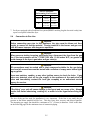
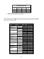
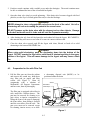
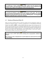
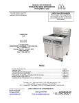
OPERATOR’S MANUAL
FRYMASTER BIPH55/MPH55 SERIES
GAS FRYER
This equipment chapter is to be
installed in the Fryer Section of the
Equipment Manual.
FOR YOUR SAFETY
Do Not Store or use gasoline or other
flammable vapors and liquids in the
vicinity of this or any other appliance.
MANUFACTURED
BY
P.O. BOX 51000
SHREVEPORT, LOUISIANA 71135-1000
PHONE: 1-318-865-1711
TOLL FREE: 1-800-551-8633
1-800-24 FRYER
FAX: 1-318-219-7135
TABLE OF CONTENTS
WARRANTY STATEMENT ..................................................................................................Page i
INTRODUCTION ..................................................................................................................Page 1-1
INSTALLATION INSTRUCTIONS .......................................................................................Page 2-1
OPERATING INSTRUCTIONS ............................................................................................Page 3-1
OPERATING THE BUILT IN FILTRATION SYSTEM ..........................................................Page 4-1
PREVENTIVE MAINTENANCE............................................................................................Page 5-1
OPERATOR TROUBLESHOOTING ....................................................................................Page 6-1
Frymaster, L.L.C. 8700 Line Avenue 71106, 5489 Campus Drive 71129
P.O. Box 51000, Shreveport, Louisiana 71135-1000
TEL 318-865-1711 FAX (Parts) 318-219-7140 (Tech Support) 318-219-7135
PRINTED IN THE UNITED STATES
www.frymaster.com
SERVICE HOTLINE
1-800-24-FRYER
Email: [email protected]
OCTOBER 2005
*8196087*
NOTICE
IF, DURING THE WARRANTY PERIOD, THE CUSTOMER USES A PART FOR THIS ENODIS
EQUIPMENT OTHER THAN AN UNMODIFIED NEW OR RECYCLED PART PURCHASED DIRECTLY
FROM FRYMASTER DEAN, OR ANY OF ITS AUTHORIZED SERVICE CENTERS, AND/OR THE PART
BEING USED IS MODIFIED FROM ITS ORIGINAL CONFIGURATION, THIS WARRANTY WILL BE
VOID. FURTHER, FRYMASTER DEAN AND ITS AFFILIATES WILL NOT BE LIABLE FOR ANY
CLAIMS, DAMAGES OR EXPENSES INCURRED BY THE CUSTOMER WHICH ARISE DIRECTLY OR
INDIRECTLY, IN WHOLE OR IN PART, DUE TO THE INSTALLATION OF ANY MODIFIED PART
AND/OR PART RECEIVED FROM AN UNAUTHORIZED SERVICE CENTER.
NOTICE
This appliance is intended for professional use only and is to be operated by qualified personnel
only. A Frymaster DEAN Factory Authorized Service Center (FASC) or other qualified professional
should perform installation, maintenance, and repairs. Installation, maintenance, or repairs by
unqualified personnel may void the manufacturer’s warranty. See Chapter 1 of this manual for
definitions of qualified personnel.
NOTICE
This equipment must be installed in accordance with the appropriate national and local codes of
the country and/or region in which the appliance is installed.
See NATIONAL CODE
REQUIREMENTS in Chapter 2 of this manual for specifics.
NOTICE TO U.S. CUSTOMERS
This equipment is to be installed in compliance with the basic plumbing code of the Building
Officials and Code Administrators International, Inc. (BOCA) and the Food Service Sanitation
Manual of the U.S. Food and Drug Administration.
NOTICE
Drawings and photos used in this manual are intended to illustrate operational, cleaning and
technical procedures and may not conform to onsite management operational procedures.
NOTICE TO OWNERS OF UNITS EQUIPPED WITH COMPUTERS
U.S.
This device complies with Part 15 of the FCC rules. Operation is subject to the following two
conditions: 1) This device may not cause harmful interference, and 2) This device must accept
any interference received, including interference that may cause undesired operation. While
this device is a verified Class A device, it has been shown to meet the Class B limits.
CANADA
This digital apparatus does not exceed the Class A or B limits for radio noise emissions as set
out by the ICES-003 standard of the Canadian Department of Communications.
Cet appareil numerique n’emet pas de bruits radioelectriques depassany les limites de classe A
et B prescrites dans la norme NMB-003 edictee par le Ministre des Communcations du Canada.
DANGER
Improper installation, adjustment, maintenance or service, and unauthorized alterations or
modifications can cause property damage, injury, or death. Read the installation, operating,
and service instructions thoroughly before installing or servicing this equipment. Only qualified
service personnel may convert this appliance to use a gas other than that for which it was
originally configured.
DANGER
No structural material on the fryer should be altered or removed to accommodate placement of
the fryer under a hood. Questions? Call the Frymaster Dean Service Hotline at 1-800-551-8633.
DANGER
Adequate means must be provided to limit the movement of this appliance without depending
upon the gas line connection. All fryers equipped with casters must be stabilized by installing
restraining chains. If a flexible gas line is used, an additional restraining cable must be
connected at all times when the fryer is in use.
The front ledge of the fryer is not a step!
from slips or contact with the hot oil.
DANGER
Do not stand on the fryer. Serious injury can result
DANGER
Do not store or use gasoline or other flammable liquids or vapors in the vicinity of this or any
other appliance.
DANGER
Instructions to be followed in the event the operator smells gas or otherwise detects a gas leak
must be posted in a prominent location. This information can be obtained from the local gas
company or gas supplier.
DANGER
This product contains chemicals known to the state of California to cause cancer and/or birth
defects or other reproductive harm.
Operation, installation, and servicing of this product could expose you to airborne particles of
glasswool or ceramic fibers, crystalline silica, and/or carbon monoxide. Inhalation of airborne
particles of glasswool or ceramic fibers is known to the State of California to cause cancer.
Inhalation of carbon monoxide is known to the State of California to cause birth defects or other
reproductive harm.
DANGER
The crumb tray in fryers equipped with a filter system must be emptied into a fireproof container
at the end of frying operations each day. Some food particles can spontaneously combust if left
soaking in certain shortening material.
WARNING
Do not bang fry baskets or other utensils on the fryer’s joiner strip. The strip is present to seal
the joint between the fry vessels. Banging fry baskets on the strip to dislodge shortening will
distort the strip, adversely affecting its fit. It is designed for a tight fit and should only be
removed for cleaning.
WARNING
To ensure the safe and efficient operation of the fryer and hood, the electrical plug for the 120volt line, which powers the hood, must be fully engaged and locked in its pin and sleeve socket.
NOTICE
The Commonwealth of Massachusetts requires any and all gas products to be installed by a
licensed plumber or pipe fitter.
WARRANTY STATEMENT
Frymaster, L.L.C. makes the following limited warranties to the original purchaser only for this
equipment and replacement parts:
A. WARRANTY PROVISIONS - FRYERS
1. Frymaster L.L.C. warrants all components against defects in material and workmanship for a
period of one year.
2. All parts, with the exception of the frypot, heating elements and fuses, are warranted for one year
after installation date of fryer.
3. If any parts, except fuses and filter O-rings, become defective during the first year after
installation date, Frymaster will also pay straight-time labor costs to replace the part, plus up to
100 miles/160 km of travel (50 miles/80 km each way).
B. WARRANTY PROVISIONS - FRYPOTS
(Applies to fryers manufactured after December 1, 2003, only.)
1. Frymaster warrants the frypot assembly for ten years parts and labor. Components attached to
the frypot, such as the high-limit, probe, gaskets, seals, ignitors and related fasteners, are also
covered by the ten-year warranty if replacement is necessitated by the frypot replacement.
Components that are not part of the frypot assembly, such as the blower, gas valve, micro
switches, doors and cabinetry are not covered by the frypot warranty. If the frypot is found to be
defective, Frymaster will replace the frypot, allowing up to the maximum time per the Frymaster
time allowance chart hours of straight-time labor plus up to 100 miles/160 km of travel (50
miles/80 km each way) to change the frypot.
2. This warranty is limited to fryers operating on natural or propane (LP) gas. Fryers that operate
on manufactured gas (also known as town gas or high-hydrogen gas) have a lifetime frypot
warranty, parts only.
C. WARRANTY PROVISIONS – COMBUSTION CHAMBERS
(Applies to fryers installed on or after November 1, 1994, only.)
1. Frymaster L.L.C. warrants the combustion chambers against defective material or workmanship
for a period of ten years from the original installation date, parts and labor.
2. The combustion chamber consists of the infrared burners and the structural components to mount
the burners. This warranty does not cover ancillary components, including the igniter, blower,
high-limit thermostat, and temperature probe.
3. This warranty is limited to fryers operating on natural or propane (LP) gas.
i
D. WARRANTY PROVISIONS - COOKING COMPUTER
1. Frymaster L.L.C. warrants the M-2000 Cooking Computer against defective material or
workmanship for a period of three years from the original installation date. If the unit fails within
the first year, warranty will cover part and labor. If the part fails the second year, warranty will
cover part only. Labor is charged to the store. The third year, warranty will cover the part at a
reduced cost of $90.00. No labor or handling will be covered.
2. During this warranty period, Frymaster will replace a returned defective cooking computer with a
new or factory rebuilt and functionally operative units.
3. For replacement of defective computers under warranty, call your local Frymaster Authorized
Service Center. All computers replaced under the Frymaster exchange program only carry the
remaining original warranty.
E. PARTS RETURN
All defective in-warranty parts must be returned to a Frymaster Authorized Factory Service Center
within 60 days for credit. After 60 days, no credit will be allowed.
F. WARRANTY EXCLUSIONS
This warranty does not cover equipment that has been damaged due to misuse, abuse, alteration, or
accident such as:
•
improper or unauthorized repair (including any frypot which is welded in the field);
•
failure to follow proper installation instructions and/or scheduled maintenance procedures as
prescribed in your MRC cards. Proof of scheduled maintenance is required to maintain the warranty;
•
improper maintenance;
•
damage in shipment;
•
abnormal use;
•
removal, alteration, or obliteration of either the rating plate or the date code on the heating elements;
•
operating the frypot without shortening or other liquid in the frypot;
•
no fryer will be warranted under the ten-year program for which a proper start-up form has not been
received.
This warranty also does not cover:
•
transportation or travel over 100 miles/160 km (50 miles/80 km each way), or travel over two hours;
•
overtime or holiday charges;
•
consequential damages (the cost of repairing or replacing other property which is damaged), loss of
time, profits, use or any other incidental damages of any kind.
There are no implied warranties of merchantability or fitness for any particular use or purpose.
This warranty is applicable at the time of this printing and is subject to change.
ii
BIPH55 / MPH55 SERIES GAS FRYER
CHAPTER 1: INTRODUCTION
1.1
General
Read the instructions in this manual thoroughly before attempting to operate this equipment. This
manual covers all configurations of models MPH55 and BIPH55 fryers. Models designated MPH55
do not have built-in filtration systems. Models designated BIPH55 are equipped with FootPrint Pro
built-in filtration systems. The fryers in this model family have most parts in common, and when
discussed as a group, will be referred to as “Pro Series H55” fryers.
Although similar in appearance to the BIH52 McDonald’s fryers, the BIPH55 fryers feature a
significantly different built-in filtration system. The new Euro-Look incorporates rounded topcaps
and large round drains, which ensures that fries and other debris will be washed into the filter pan.
Other features, including the deep cold-zones and easy to clean, open frypots remain essentially
unchanged. All Pro Series H55 Gas fryers come standard with M2000 computer, electronic ignition,
melt cycle, and boil-out mode.
Fryers in this series come in full- or split-vat arrangements, and can be purchased as single units or
in batteries of up to five fryers.
Pro Series H55 high-efficiency gas fryers employ a unique infrared burner system that uses up to
43% less energy to cook the same volume as conventional open-burner fryers.
All Pro Series H55 Gas fryers are of an open-frypot design with no tubes and have a hand-sized
opening into the deep cold zone, which makes cleaning the stainless frypot quick and easy.
Heating is supplied by a pair of infrared burner assemblies mounted on each side of the frypot. A
dedicated blower mounted on the front of the frypot supplies combustion air for the burners. Pro
Series H55 Gas fryers can be configured for natural gas, propane (LP), or manufactured gas, as
required by the customer.
Each frypot is equipped with a temperature probe for precise temperature control.
All fryers in this series require an external source of AC electrical power. Units can be configured
for voltages ranging from 100 VAC to 240 VAC.
BIPH55 and MPH55 fryers are shipped completely assembled. All fryers are shipped with a package
of standard accessories. Each fryer is adjusted, tested, and inspected at the factory before crating for
shipment.
This appliance is only for professional use and shall be used by qualified personnel only, as
defined in Section 1.6.
1-1
1.2
Safety Information
Before attempting to operate your unit, read the instructions in this manual thoroughly. Throughout
this manual, you will find notations enclosed in double-bordered boxes similar to the ones that
follow.
CAUTION
CAUTION boxes contain information about actions or conditions that may cause or result
in a malfunction of your system.
WARNING
WARNING boxes contain information about actions or conditions that may cause or result
in damage to your system, and which may cause your system to malfunction.
DANGER
DANGER boxes contain information about actions or conditions that may cause or result
in injury to personnel, and which may cause damage to your system and/or cause your
system to malfunction.
Your fryer is equipped with automatic safety features:
1. High temperature detection shuts off gas to the burner assembly should the controlling
thermostat fail.
2. A safety switch built into the drain valve on units with filter systems prevents burner ignition
with the drain valve even partially open.
1.3
Computer Information for the M2000 Computers
FCC COMPLIANCE
This equipment has been tested and found to comply with the limits for a Class A digital device, pursuant to Part 15 of the FCC rules. While this device is a verified Class A device, it has been shown
to meet the Class B limits. These limits are designed to provide reasonable protection against harmful interference when the equipment is operated in a commercial environment. This equipment
generates, uses and can radiate radio frequency energy and, if not installed and used in accordance
with the instruction manual, may cause harmful interference to radio communications.
Operation of the equipment in a residential area is likely to cause harmful interference in which case
the user will be required to correct the interference at his own expense.
The user is cautioned that any changes or modifications not expressly approved by the party responsible for compliance could void the user's authority to operate the equipment.
If necessary, the user should consult the dealer or an experienced radio and television technician for
additional suggestions.
1-2
The user may find the following booklet prepared by the Federal Communications Commission
helpful: "How to Identify and Resolve Radio-TV Interference Problems". This booklet is available
from the U.S. Government Printing Office, Washington, DC 20402, Stock No. 004-000-00345-4.
1.4
European Community (CE) Specific Information
The European Community (CE) has established certain specific standards regarding equipment of
this type. Whenever a conflict exists between CE and non-CE standards, the information or
instructions concerned are identified by means of shadowed boxes.
1.5
Installation, Operating, and Service Personnel
Operating information for Frymaster equipment has been prepared for use by qualified and/or
authorized personnel only, as defined in Section 1.6. All installation and service on Frymaster
equipment must be performed by qualified, certified, licensed, and/or authorized installation
or service personnel, as defined in Section 1.6.
1.6
Definitions
QUALIFIED AND/OR AUTHORIZED OPERATING PERSONNEL
Qualified/authorized operating personnel are those who have carefully read the information in this
manual and have familiarized themselves with the equipment functions, or who have had previous
experience with the operation of the equipment covered in this manual.
QUALIFIED INSTALLATION PERSONNEL
Qualified installation personnel are individuals, firms, corporations, and/or companies which, either
in person or through a representative, are engaged in and are responsible for the installation of gasfired appliances. Qualified personnel must be experienced in such work, be familiar with all gas
precautions involved, and have complied with all requirements of applicable national and local
codes.
QUALIFIED SERVICE PERSONNEL
Qualified service personnel are those who are familiar with Frymaster equipment and who have been
authorized by Frymaster, L.L.C. to perform service on the equipment. All authorized service
personnel are required to be equipped with a complete set of service and parts manuals, and to stock
a minimum amount of parts for Frymaster equipment. A list of Frymaster Factory Authorized
Service Centers (FASC) is included with the fryer when shipped from the factory. Failure to use
qualified service personnel will void the Frymaster warranty on your equipment.
1-3
1.7
Shipping Damage Claim Procedure
Your Frymaster equipment was carefully inspected and packed before leaving the factory. The
transportation company assumes full responsibility for safe delivery upon its acceptance of the
equipment for transport.
What to do if your equipment arrives damaged:
1. File a claim for damages immediately, regardless of the extent of damages.
2. Inspect for and record all visible loss or damage, and ensure that this information is noted on
the freight bill or express receipt and is signed by the person making the delivery.
3. Concealed loss or damage that was unnoticed until the equipment was unpacked should be
recorded and reported to the freight company or carrier immediately upon discovery. A
concealed damage claim must be submitted within 15 days of the date of delivery. Ensure that
the shipping container is retained for inspection.
Frymaster
1.8
DOES NOT ASSUME RESPONSIBILITY FOR DAMAGE OR LOSS
INCURRED IN TRANSIT.
Parts Ordering and Service Information
For non-routine maintenance or repairs, or for service information, contact your local Frymaster
Authorized Service Center (FASC). In order to assist you quickly, the Frymaster Factory
Authorized Service Center (FASC) or Service Department representative requires certain
information about your equipment. Most of this information is printed on a data plate affixed to the
inside of the fryer door. Part numbers are found in the Installation, Operation, Service, and Parts
Manual. Parts orders may be placed directly with your local FASC or distributor. Included with
fryers when shipped from the factory is a list of Frymaster FASCs. If you do not have access to this
list, contact the Frymaster Service Department at 1-800-551-8633 or 1-318-865-1711.
When ordering parts, the following information is required:
Model Number:
Serial Number:
Type of Gas or Voltage:
Item Part Number:
Quantity Needed:
1-4
Service information may be obtained by contacting your local FASC/Distributor. Service may also
be obtained by calling the Frymaster Service Department at 1-800-551-8633 or 1-318-865-1711.
When requesting service, please have the following information ready:
Model Number:
Serial Number:
Type of Gas:
In addition to the model number, serial number, and type of gas, please be prepared to describe the
nature of the problem and have ready any other information that you think may be helpful in solving
your problem.
RETAIN AND STORE THIS MANUAL IN A SAFE PLACE FOR FUTURE USE.
1-5
BIPH55 / MPH55 SERIES GAS FRYER
CHAPTER 2: INSTALLATION INSTRUCTIONS
2.1
General Installation Requirements
Qualified, licensed, and/or authorized installation or service personnel, as defined in Section
1.6 of this manual, should perform all installation and service on Frymaster equipment.
Conversion of this appliance from one type of gas to another should only be performed by
qualified, licensed, and/or authorized installation or service personnel as defined in Section 1.6
of this manual.
Failure to use qualified, licensed, and/or authorized installation or service personnel (as defined in Section 1.6 of this manual) to install, convert to another gas type or otherwise service
this equipment will void the Frymaster warranty and may result in damage to the equipment
or injury to personnel.
Where conflicts exist between instructions and information in this manual and local or national codes or regulations, installation and operation shall comply with the codes or regulations in force in the country in which the equipment is installed.
DANGER
Building codes prohibit a fryer with its open tank of hot oil being installed beside an
open flame of any type, including those of broilers and ranges.
Upon arrival, inspect the fryer carefully for visible or concealed damage. (See Shipping Damage
Claim Procedure in Section 1.7 of this manual.)
DANGER
Frymaster appliances equipped with legs are for stationary installations. Appliances
fitted with legs must be lifted during movement to avoid damage to the appliance
and bodily injury. For movable installations, optional equipment casters must be
used. Questions? Call 1-800-551-8633.
2.1.1 CLEARANCE AND VENTILATION
The fryer(s) must be installed with a 6” (150 mm) clearance at both sides and back when installed
adjacent to combustible construction; no clearance is required when installed adjacent to
noncombustible construction. A minimum of 24” (600 mm) clearance should be provided at the
front of the fryer.
WARNING
Do not block the area around the base or under the fryers.
2-1
DANGER
No structural material on the fryer should be altered or removed to accommodate
placement of the fryer under a hood. Questions? Call the Frymaster Dean Service
Hotline at 1-800-551-8633.
One of the most important considerations of efficient fryer operation is ventilation. Make sure the
fryer is installed so that products of combustion are removed efficiently, and that the kitchen
ventilation system does not produce drafts that interfere with burner operation.
The fryer flue opening must not be placed close to the intake of the exhaust fan, and the fryer must
never have its flue extended in a “chimney” fashion. An extended flue will change the combustion
characteristics of the fryer, causing longer recovery time. It also frequently causes delayed ignition.
To provide the airflow necessary for good combustion and burner operation, the areas surrounding
the fryer front, sides, and rear must be kept clear and unobstructed.
DANGER
This appliance must be installed with sufficient ventilation to prevent the occurrence
of unacceptable concentrations of substances harmful to the health of personnel in
the room in which it is installed.
Fryers must be installed in an area with an adequate air supply and adequate ventilation. Adequate
distances must be maintained from the flue outlet of the fryer to the lower edge of the ventilation
filter bank. Filters should be installed at an angle of 45º. Place a drip tray beneath the lowest edge
of the filter. For U.S. installation, NFPA standard No. 96 states, “A minimum distance of 18 in.
(450 mm) should be maintained between the flue outlet and the lower edge of the grease filter.”
Frymaster recommends that the minimum distance be 24 in. (600 mm) from the flue outlet to the
bottom edge of the filter when the appliance consumes more than 120,000 BTU per hour.
For installations in the United States, information on construction and installation of ventilating
hoods can be found in the NFPA standard cited above. A copy of the standard may be obtained
from the National Fire Protection Association, Battery March Park, Quincy, MA 02269.
2.1.2 NATIONAL CODE REQUIREMENTS
The type of gas for which the fryer is equipped is stamped on the data plate attached to the inside of
the fryer door. Connect a fryer stamped “NAT” only to natural gas, those stamped “PRO” only to
propane gas, and those stamped “MFG” only to manufactured gas.
Installation shall be made with a gas connector that complies with national and local codes, and,
where applicable, CE codes. Quick-disconnect devices, if used, shall likewise comply with national,
local, and, if applicable, CE codes.
2.1.3 ELECTRICAL GROUNDING REQUIREMENTS
All electrically operated appliances must be grounded in accordance with all applicable national and
local codes, and, where applicable, CE codes. All units (cord connected or permanently connected)
should be connected to a grounded power supply system. A wiring diagram is located on the inside
of the fryer door. Refer to the rating plate on the inside of the fryer door for proper voltages.
2-2
DANGER
This appliance is equipped with a special (grounding) plug for your protection
against electrical shock, and must be plugged directly into a properly grounded receptacle. Do not cut, remove, or otherwise bypass the grounding prong on this
plug!
DANGER
This appliance requires electrical power for operation. Place the gas control valve in
the OFF position in case of a prolonged power outage. Do not attempt to operate
this appliance during a power outage.
WARNING
To ensure the safe and efficient operation of the fryer and hood, the electrical plug
for the 120-volt line, which powers the hood, must be fully engaged and locked in its
pin and sleeve socket.
2.1.4 Australian Requirements
To be installed in accordance with AS 5601 / AG 601, local authority, gas, electricity, and any other
relevant statutory regulations.
2.2
Caster Installation
Depending upon the specific configuration ordered, your fryer may have been shipped without
installed casters. DO NOT INSTALL THIS APPLIANCE WITHOUT CASTERS. If the
appliance requires the installation of casters, install them in accordance with the instructions
included in your accessory package.
2.3
Pre-Connection Preparations
DANGER
DO NOT connect this appliance to the gas supply before completing each step in
this section.
After the fryer has been positioned under the exhaust hood, ensure the following has been
accomplished:
1. Adequate means must be provided to limit the movement of fryers without depending upon the
gas line connections. If a flexible gas hose is used, a restraining cable must be connected at all
times when the fryer is in use. The restraining cable and installation instructions are packed with
the flexible hose in the accessories box that was shipped with your unit.
2. Single unit fryers must be stabilized by installing restraining chains on fryers equipped with
casters. Follow the instructions in the accessory pack to install the chains.
2-3
DANGER
The appliance area must be kept free and clear of combustible material at all times.
3. Frymaster recommends that the minimum distance from the flue outlet to the bottom edge of the
hood be 24 in. (600 mm) when the appliance consumes more than 120,000 BTU per hour.
NOTE: There are no built-in leveling devices on fryers equipped with casters. The floor where
the fryer is to be installed must be level.
4. Test the fryer electrical system:
a. Plug the fryer electrical cord(s) into a grounded electrical receptacle. NOTE: To ensure the
safe and efficient operation of the fryer and hood, the electrical plug for the 120-volt
line, which powers the hood, must be fully engaged and locked in its pin and sleeve
socket.
b. Place the power switch in the ON position.
•
•
For fryers having computers, verify that the display indicates OFF.
If the store is equipped with a hood interlock system, the hood exhaust fan should be on.
If not, the store hood interlock system is improperly wired and must be corrected.
c. Place the fryer power switch in the OFF position. Verify that the power and heat lights are
out.
5. Refer to the data plate on the inside of the fryer door to determine if the fryer burner is
configured for the proper type of gas before connecting the fryer quick-disconnect device or
piping from the gas supply line.
6. Verify the minimum and maximum gas supply pressures for the type of gas to be used in
accordance with the accompanying tables.
CE Standard
for Incoming Gas Pressures
for Fryers Manufactured After April 1999
Pressure
(1)
Orifice Diameter
Single
Dual
Vat
Vat
Regulator Pressure
Single
Dual
Vat
Vat
Gas
G20
(mbar)
20
2 x 3.40 2 x 3.40
7 mbar
7 mbar
G25
20 or 25
2 x 3.40 2 x 3.40
10 mbar
10 mbar
G30
G31
28/30 or 50 2 x 2.05 2 x 2.05
37 or 50
2 x 2.05 2 x 2.05
(1) mbar = 10,2 mm H2O
2-4
17 mbar
17 mbar
20 mbar
20 mbar
Non-CE Standard
for Incoming Gas Pressures
Gas
Natural
LP
Minimum
6" W.C.
1.49 kPa
14.93 mbar
Maximum
14" W.C.
3.48 kPa
34.84 mbar
11" W.C.
2.74 kPa
27.37 mbar
14" W.C.
3.48 kPa
34.84 mbar
7. For fryers equipped with a FootPrint Pro system (BIPH55 models) plug the electrical cord(s) into
a power receptacle behind the fryer.
2.4
Connection to Gas Line
DANGER
Before connecting new pipe to this appliance, the pipe must be blown out thoroughly to remove all foreign material. Foreign material in the burner and gas controls will cause improper and dangerous operation.
DANGER
When pressure-testing incoming gas supply lines, disconnect the fryer from the gas
line if the test pressure will be ½ PSIG (3.45 kPa, 13.84 inches W.C.) or greater to
avoid damage to the fryer’s gas tubes and gas valve(s).
DANGER
All connections must be sealed with a joint compound suitable for the gas being
used and all connections must be tested with a solution of soapy water before lighting any pilots.
Never use matches, candles, or any other ignition source to check for leaks. If gas
odors are detected, shut off the gas supply to the appliance at the main shut-off
valve and immediately contact the local gas company or an authorized service
agency for service.
DANGER
“Dry-firing” your unit will cause damage to the frypot and can cause a fire. Always
ensure that melted shortening, cooking oil, or water is in the frypot before firing the
unit.
The size of the gas line used for installation is very important. If the line is too small, the gas
pressure at the burner manifold will be low. This may cause slow recovery and delayed ignition.
The incoming gas supply line should be a minimum of 1½” (38 mm) in diameter. Refer to the chart
on the following page for the minimum sizes of connection piping.
2-5
Gas Connection Pipe Sizes
(Minimum incoming pipe size should be 1 1/2" (41 mm))
Gas
Natural
Single Unit
3/4" (22 mm)
Propane
1/2" (15 mm)
Manufactured
•
1" (28 mm)
2 - 3 Units
1" (28 mm)
4 or more
units*
1 1/4" (36 mm)
3/4" (22 mm)
1" (28 mm)
1 1/4" (36 mm) 1 1/2" (41 mm)
For distances of more than 20 feet (6 m) and/or more than 4 fittings or
elbows, increase the connection by one pipe size.
The Pro Series H55 gas fryer has received the CE mark for the countries and gas categories
indicated in the table below. NOTE: The nominal heat input (QN) is 21kW except for AT, DE, LU
and category 3P/B, which is 23kW.
CE Approved Gas Categories by Country
COUNTRIES
CATEGORIES
AUSTRIA (AT)
II2H3B/P
BELGIUM (BE)
I2E(R)B
I3+
DENMARK (DK)
II2H3B/P
II2Esi3+
FRANCE (FR)
II2Esi3P
FINLAND (FI)
GERMANY (DE)
II2H3B/P
II2ELL3B/P
I3P
GREECE (GR)
II2H3+
ITALY (IT)
II2H3+
IRELAND (IE)
II2H3+
LUXEMBOURG (LU)
II2E3B/P
II2L3P
NETHERLANDS (NL)
II2L3B/P
NORWAY (NO)
I3B/P
PORTUGAL (PT)
II2H3+
II2H3+
SPAIN (ES)
II2H3P
SWEDEN (SE)
UNITED KINGDOM (UK)
II2H3B/P
II2H3+
2-6
GAS
G20
G30, G31
G20, G25
G30, G31
G20
G30, G31
G20, G25
G30, G31
G20, G25
G31
G20
G30, G31
G20, G25
G30, G31
G31
G20
G30, G31
G20
G30, G31
G20
G30, G31
G20
G30, G31
G25
G31
G25
G30, G31
G30, G31
G20
G30, G31
G20
G30, G31
G20
G31
G20
G30, G31
G20
G30, G31
PRESSURE (MBAR)
20
50
20, 25
28-30, 37
20
30
20, 25
28-30, 37
20, 25
50
20
30
20
50
50
20
28-30, 37
20
28-30, 37
20
28-30, 37
20
50
25
50
25
30
30
20
28-30, 37
20
28-30, 37
20
37, 50
20
30
20
28-30, 37
CE Standard
Required airflow for the combustion air supply is 2m3/h per kW.
1. Connect the quick-disconnect hose to the fryer quick-disconnect fitting under the front of the
fryer and to the building gas line.
NOTE: Some fryers are configured for a rigid connection to the gas supply line. These units
are connected to the gas supply line at the rear of the unit.
When using thread compound, use very small amounts on male threads only. Use a pipe thread
compound that is not affected by the chemical action of LP gases (Loctite™ PST56765 Sealant
is one such compound). DO NOT apply compound to the first two threads. Doing so may allow
some of the compound to enter the gas stream, resulting in clogging of burner orifices and/or the
control valve.
2. Open the gas supply to the fryer and check all piping, fittings, and gas connections for leaks. A
soap solution should be used for this purpose.
3. Close the fryer drain valve and fill the frypot with water and boil-out solution to the bottom
OIL LEVEL line at the rear of the frypot. Light the fryer and perform the boil-out procedures
that are described in the “Lighting Instructions” and “Boiling Out the Frypot” topics found in
Chapter 3 of this manual.
DANGER
“Dry-firing” your unit will cause damage to the frypot and can cause a fire. Always
ensure that melted shortening, cooking oil, or water is in the frypot before firing your
unit.
4. The burner manifold pressure should be checked at this time by the local gas company or an
authorized service agent. The tables below and on the following page list the burner manifold
gas pressures for the various gas types that can be used with this equipment.
CE Standard
Burner Manifold Gas Pressures
for Fryers Manufactured After April 1999
Pressure (mbar)
Gas
Natural Gas Lacq
(G20) under 20 mbar
Natural Gas Groningue *
(G25) under 25 mbar
Natural Gas Groningue
(G25) under 20 mbar
Butane
(G30) at 28/30 or 50 mbar
Propane
(G31) under 37 or 50 mbar
Single
Vat
Dual
Vat
7
7
10
10
10
10
17
17
20
20
* Belgian G25 = 7,0 mbar (single or dual)
2-7
Non-CE Sta nda rd
Burne r Ma nifold Ga s Pre ssure s
Gas
Pr e s s ur e
3" W.C.
0.73 kPa
8.25" W.C.
2.5 kPa
Natural
Propane
5. Check the programmed temperature thermostat setting. (Refer to the separate M2000 Manual
furnished with your unit for the setpoint programming instructions for your particular controller.)
2.5
Converting to Another Gas Type
DANGER
This appliance was configured at the factory for a specific type of gas. Converting
from one type of gas to another requires the installation of specific gas-conversion
components.
Switching to a different type of gas without installing the proper conversion
components may result in fire or explosion. NEVER ATTACH THIS APPLIANCE TO A
GAS SUPPLY FOR WHICH IT IS NOT CONFIGURED!
Conversion of this appliance from one type of gas to another should only be
performed by qualified, licensed, and authorized installation or service personnel, as
defined in Section 1.6 of this manual.
Pro Series H55 gas fryers manufactured for Non-CE countries use different burners for each type
gas. The burners in fryers built for propane gas have a special gray-colored coating on the burner
tiles to enable them to withstand the higher caloric value of the propane gas. Burners designed for
use in propane units may be used in natural gas applications, but not vice versa.
Non-CE Gas Conversion Kits
Natural Gas to Propane (LP) Gas
Propane (LP) Gas to Natural Gas
Full Vat: Part Number 826-1145
Full Vat: Part Number 826-1146
Dual Vat: Part Number 826-1147
Dual Vat: Part Number 826-1148
Units manufactured for export to CE countries are equipped with “universal” burners that may be
used with either natural (G20, G25) gas or butane (G30) and propane (G31) gasses.
2-8
CE GAS CONVERSION INSTRUCTIONS
1. Between G20- and G25-type natural gas, adjust the gas pressure at the regulator. (Refer to the
CE Standard Burner Manifold Gas Pressure Chart.) Do not change the orifice.
2. Between a 2nd family (G20 or G25) and a 3rd family gas (G30 butane or G31 propane):
a. Change the orifices.
b. Adjust the manifold pressure.
3. Affix the new label include with the conversion kit next to the existing rating plate stating that
the gas type has been converted. Remove any references to the previously used gas from the
existing rating plate. Conversion rating label PN 802-2144.
4. If the destination language changes, replace the labels. Call your local service agency or KES
for a label kit. The language of reference will be on the corner of the label.
2.6
After the Fryers Are Positioned At the Frying Station
1. Once the fryer has been positioned at the frying station, use a carpenter’s level placed across the
top of the frypot to verify that the unit is level, both side-to-side and front-to-back.
To level fryers, adjust the casters being careful to ensure the fryer(s) are at the proper height in
the frying station.
DANGER
Hot oil can cause severe burns. Avoid contact. Under all circumstances, oil must be
removed from the fryer before attempting to move it to avoid spills, falls, and severe
burns. Fryers may tip and cause personal injury if not secured in a stationary position.
2. Close fryer drain-valve(s) and fill frypot with water to the bottom oil level line.
3. Boil out frypot(s) in accordance with the instructions in Section 5.3.2.1 of this manual.
4. Drain, clean, and fill frypot(s) with cooking oil. (See Equipment Setup and Shutdown Procedures in Chapter 3.)
2-9
BIPH55 / MPH55 SERIES GAS FRYER
CHAPTER 3: OPERATING INSTRUCTIONS
FINDING YOUR WAY AROUND THE BIPH55 SERIES GAS FRYER
Flue Cap
Basket Hangers
Flue
Control Panel (M2000
Computer Shown)
Top Cap
Gas Valve
Gas Valve
Combustion
Blower
Filter Control Handles
Drain Handles
Combustion
Blower
FootPrint Pro Built-in
Filtration Unit
TYPICAL CONFIGURATION (BIPH255 SHOWN)
NOTE: The appearance of your fryer may differ slightly from that
shown depending upon configuration and date of manufacture.
3-1
3.1
Equipment Setup and Shutdown Procedures
WARNING
The on-site supervisor is responsible for ensuring that operators are made aware of
the inherent hazards of operating a hot oil filtering system, particularly the aspects
of oil filtration, draining and cleaning procedures.
CAUTION
If this is the first time the fryer is being used after installation, refer to the frypot BoilOut Procedure in Section 5.3.2.1 of this manual.
CAUTION
The oil/shortening capacity of the Pro Series gas fryer is 50 lbs. (25 liters) at 70°F
(21°C) for a full-vat and 25 lbs. (12.5 liters) at 70°F (21°C) for each half of a dual-vat.
Before lighting the fryer, make sure the fryer is OFF and the frypot drain valve(s)
is/are closed. Remove the basket support rack(s), if installed, and fill the frypot to
the bottom OIL-LEVEL line.
If solid shortening is being used, make sure it is packed down into the bottom of the
frypot.
3.1.1 Setup
WARNING
Never operate this appliance with an empty frypot. The frypot must be filled with water or oil/shortening before lighting the burners. Failure to do so will damage the
frypot and may cause a fire.
DANGER
Remove all drops of water from the frypot before filling with oil. Failure to do so will
cause spattering of hot liquid when the oil is heated to cooking temperature.
1. Fill the frypot with cooking oil to the bottom OIL LEVEL line located on the rear of the frypot.
This will allow for oil expansion as heat is applied. Do not fill cold oil any higher than the bottom line; overflow may occur as heat expands the oil.
2. Ensure that the power cord(s) is/are plugged into the appropriate receptacle(s). Verify that the
face of the plug is flush with the outlet plate, with no portion of the prongs visible.
3. Ensure that the oil level is at the top OIL LEVEL line when the oil is at its cooking temperature.
It may be necessary to add oil to bring the level up to the proper mark, after it has reached cooking temperature.
3-2
3.1.2 Lighting the Fryer
1. Press the computer ON/OFF switch to the OFF position.
After placing the ON/OFF switch in the OFF
position, turn the gas valve knob to the OFF
position. Wait 5 minutes, then turn the knob
to the ON postion and proceed with Step 2.
OFF
ON
OFF
ON
Placing the ON/OFF switch in the OFF
position also turns off the gas valve. Wait five
minutes before continuing with Step 2, which
will also turn on the gas valve.
Honeywell
For Non-CE Fryers
Honeywell
For CE Fryers
2. Press the computer ON/OFF switch to the ON position.
3. If the burners fail to light, press the ON/OFF switch to the OFF position and wait 60 seconds.
Repeat step 2.
4. The fryer will automatically enter the melt cycle mode if the frypot temperature is below 180ºF
(82ºC). (NOTE: During the melt cycle, the burners will repeatedly fire for a few seconds, then
go out for a longer period.) When the frypot temperature reaches 180ºF (82ºC), the unit will
automatically switch to the heating mode. The burners will remain lit until the frypot
temperature reaches the programmed cooking temperature.
5. After the burners have been lit for at least 90 seconds, observe the flames through the burner
viewing ports located on each side of the combustion air blower.
1
2
3
4
5
6
7
8
9
0
1
2
3
4
5
6
7
8
9
0
*
*
+
+
AB C
DEF
GHI
JKL
MNO
P QR
STU
V WX
Y ZA BC
Left Viewing Ports are
behind the motor
housings.
DE F
GHI
JK L
MNO
PQR
S TU
VWX
YZ-
Right Viewing Ports
The optimum burn is a bright orange-red glow. If a blue flame is observed, or if there are dark spots
on a burner face, adjust the air gas mixture as follows: On the side of the blower housing opposite
the motor is a plate with a locking nut. Loosen the nut enough to allow the plate to be moved, then
adjust the position of the plate to open or close the air intake opening until a bright orange-red glow
is obtained. Carefully hold the plate in position and tighten the locking nut.
3-3
3.1.3 Shutdown
For short-term shut down during the workday:
1. Place the computer ON/OFF switch in the OFF position and put the frypot covers in place.
When shutting the fryers down at closing time:
1. Place the computer ON/OFF switch in the OFF position to turn the fryer off.
OFF
OFF
ON
After placing the ON/OFF switch in the OFF
position, turn the gas valve knob to the OFF
position.
Honeywell
Placing the ON/OFF switch in the OFF
position also turns off the gas valve.
ON
For Non-CE Fryers
Honeywell
For CE Fryers
2. Filter the oil and clean the fryers (See Chapters 4 and 5).
3. Place the frypot covers on the frypots.
3.2
Boiling Out the Frypot
To ensure that the frypot is free of any contamination resulting from its manufacture, shipping, and
handling during installation, the frypot must be boiled out before first use. Refer to Drain and Clean
Frypot (page 5-2) for this procedure.
3.3
Operation
This fryer is equipped with M2000 computers (illustrated below). Refer to the separate M2000 Computer Operating Instructions furnished with the fryer for the computer programming and operating
procedures.
M2000 COMPUTER
3-4
BIPH55 / MPH55 SERIES GAS FRYER
CHAPTER 4: FILTRATION INSTRUCTIONS
4.1
Introduction
The FootPrint Pro filtration system allows the oil in one frypot to be safely and efficiently filtered
while the other frypots in a battery remain in operation.
Section 4.3 covers preparation of the filter system for use. Operation of the system is covered in
section 4.4.
WARNING
The on-site supervisor is responsible for ensuring that operators are made aware of
the inherent hazards of operating a hot oil filtering system, particularly the aspects
of oil filtration, draining and cleaning procedures.
4.2
Draining and Manual Filtering
DANGER
Draining and filtering of oil must be accomplished with care to avoid the possibility
of a serious burn. The oil to be filtered is at or near 350°F (177°C). Ensure all hoses
are connected properly and drain handles are in their proper position before
operating any switches or valves. Wear all appropriate safety equipment when
draining and filtering oil.
DANGER
Allow oil to cool to 100°F (38°C) before draining into an appropriate container for
disposal.
DANGER
Do not drain more than one frypot at a time into the built-in filtration unit to avoid
overflow and spillage of hot oil.
DANGER
When draining oil into a disposal unit or portable filter unit, do not fill above the
maximum fill line located on the container.
If your fryer is not equipped with a built-in filtration system, the oil must be drained into another
suitable container. (For safe, convenient draining and disposal of used oil, Frymaster recommends
using the McDonald’s Shortening Disposal Unit (MSDU). The MSDU is available through your
local distributor.)
1. Turn the fryer power switch to the OFF position. Screw the drainpipe (provided with your fryer)
into the drain valve. Make sure the drainpipe is firmly screwed into the drain valve and that the
opening is pointing down.
4-1
2. Position a metal container with a sealable cover under the drainpipe. The metal container must
be able to withstand the heat of the oil and hold hot liquids.
3. Open the drain valve slowly to avoid splattering. If the drain valve becomes clogged with food
particles, use the Fryer’s Friend (poker-like tool) to clear the blockage.
DANGER
NEVER attempt to clear a clogged drain valve from the front of the valve! Hot oil or
shortening will rush out creating the potential for severe burns.
DO NOT hammer on the drain valve with the cleanout rod or other objects. Damage
to the ball inside will result in leaks and will void the Frymaster warranty.
4. After draining the oil, clean all food particles and residual oil from the frypot. BE CAREFUL,
this material may still cause severe burns if it comes in contact with bare skin.
5. Close the drain valve securely and fill the frypot with clean, filtered or fresh oil or solid
shortening to the bottom OIL-LEVEL line.
DANGER
When using solid shortening, pack the shortening down into the bottom of the
frypot. DO NOT operate the fryer with a solid block of shortening sitting in the upper
portion of the frypot. This will cause damage to the frypot and may cause a flash
fire.
4.3
Preparation for Use with Filter Pad
1. Pull the filter pan out from the cabinet
and remove the crumb tray, hold-down
ring, filter pad (or paper) and filter
screen. (See Figure 1) Clean all
components with a solution of
McDonald’s All Purpose Concentrate
and hot water, then dry thoroughly.
The filter pan is equipped with rollers in
rails, much like a kitchen drawer. The
pan may be removed for cleaning or to
gain access to interior components by
lifting the front of the pan to disengage
the front rollers, then pulling it forward
until the rear rollers clear the rails. The
pan cover must not be removed except
for cleaning, interior access, or to allow
a shortening disposal unit (MSDU) to be
positioned under the drain.
Screen
Filter Pad or
Filter Paper
Crumb Tray
Hold-Down Ring
Figure 1
4-2
2. Inspect the filter pan connection fitting
to ensure that both O-rings are in good
condition. (See Figure 2)
Inspect the filter
connection fitting
O-rings.
Figure 2
3. Then in reverse order, place the metal filter screen in the center of the bottom of the pan, then lay
a filter pad over the screen, ensuring that the textured side of the pad is up. Make sure that the
pad is in between the embossed ridges of the filter pan then position the hold down ring on top of
the pad. If using filter paper, lay a sheet of filter paper over the top of the pan overlapping on all
sides. Position the hold down ring over the filter paper and lower the ring into the pan, allowing
the paper to fold up and around the ring as it is pushed to the bottom of the pan. Then sprinkle 8ounces of filter powder over the filter paper.
4.
Reinstall the crumb tray at the front of the pan. (See Figure 1)
DO NOT use filter powder with the pad!
5. Replace the crumb tray in the filter pan. Push the filter pan back into the fryer, positioning it all
the way to the back of the cabinet. The filtration system is now ready for use.
4.4
Operation of the Filter
DANGER
Draining and filtering of oil must be accomplished with care to avoid the possibility
of a serious burn. The oil to be filtered is at or near 350°F (177°C). Ensure drain
handles are in their proper position before operating any switches or valves. Wear
all appropriate safety equipment when draining and filtering cooking oil.
DANGER
NEVER attempt to drain oil from the fryer with the burners lit! Doing so will cause
irreparable damage to the frypot and may cause a flash fire. Doing so will also void
the Frymaster warranty.
1. Turn the fryer power OFF. Drain the
frypot into the filter pan by rotating the
larger handle valves to the right. If
necessary, use the Fryer's Friend cleanout rod to clear the drain from inside the
frypot.
Open drain valves
by rotating handles
to the right.
DANGER
Do not drain more than one full vat or a split vat frypot at a time into the built-in
filtration unit to avoid overflow and spillage of hot oil.
4-3
DANGER
NEVER attempt to clear a clogged drain valve from the front of the valve! Hot oil will
rush out creating the potential for severe burns.
DO NOT hammer on the drain valve with the cleanout rod or other objects. Damage
to the ball inside will result in leaks and will void the Frymaster warranty.
2. After the oil has drained from the frypot,
rotate the filter handle to start the pump
and begin the filtering process. There
may be a slight delay before the pump
activates.
Rotate smaller
handle to
activate filter.
3. The filter pump draws the oil through the filter pad and circulates it back up to and through the
frypot during a 5-minute process called polishing. Polishing cleans the oil by trapping solid
particles in the filter pad.
4. After the oil is filtered (about 5 minutes), close the drain valve and allow the fryer to refill. Let
the filter pump run 15 to 30 seconds after the oil begins to bubble in the frypot then turn the filter
off but rotating the handle up.
WARNING
The filter pump is equipped with a manual reset switch in case the filter motor
overheats or an electrical fault occurs. If this switch trips, turn off power to the filter
system and allow the pump motor to cool 20 minutes before attempting to reset the
switch (see photo below).
Filter Pump Reset Switch
5. Ensure the drain valve is fully closed. (If the drain valve is not fully closed, the fryer will not
operate.) Turn the fryer ON and allow the oil to reach setpoint.
4-4
DANGER
The crumb tray in fryers equipped with a filter system must be emptied into a
fireproof container at the end of frying operations each day. Some food particles can
spontaneously combust if left soaking in certain shortening material.
WARNING
Do not bang fry baskets or other utensils on the fryer’s joiner strip. The strip is
present to seal the joint between the fry vessels. Banging fry baskets on the strip to
dislodge shortening will distort the strip, adversely affecting its fit. It is designed for
a tight fit and should only be removed for cleaning.
4.5
Draining and Disposing of Waste Oil
When your oil has reached the end of its usable life, drain the oil into an appropriate container for
transport to the disposal container. Frymaster recommends the use of the McDonald’s Shortening
Disposal Unit (MSDU). NOTE: If using an MSDU built before January 2004, the filter pan cover
must be removed to allow the unit to be positioned beneath the drain. To remove the lid, lift up on
the front edge and pull it straight out of the cabinet. Refer to the documentation furnished with your
disposal unit for specific operating instructions. If a shortening disposal unit is not available, allow
the oil to cool to 100°F (38°C), then drain the oil into a metal stockpot or similar metal container.
When draining is finished, close the fryer drain valve securely.
DANGER
Allow oil to cool to 100°F (38°C) before draining into an appropriate container for
disposal.
When draining oil into a disposal unit, do not fill above the maximum fill line located
on the container.
4-5
BIPH55 / MPH55 SERIES GAS FRYER
CHAPTER 5: PREVENTIVE MAINTENANCE
5.1
Fryer Preventive Maintenance Checks and Service
DANGER
The crumb tray in fryers equipped with a filter system must be emptied into a fireproof container at the end of frying operations each day. Some food particles can
spontaneously combust if left soaking in certain shortening material.
WARNING
Use McDonald’s All Purpose Concentrate. Read the directions for use and precautionary statements before use. Particular attention must be paid to the
concentration of cleaner and the length of time the cleaner remains on the foodcontact surfaces.
5.2
DAILY CHECKS AND SERVICE
5.2.1 Inspect Fryer and Accessories for Damage
Look for loose or frayed wires and cords, leaks, foreign material in frypot or inside cabinet, and any
other indications that the fryer and accessories are not ready and safe for operation.
5.2.2 Clean Fryer Cabinet Inside and Out
Clean inside the fryer cabinet with dry, clean cloth. Wipe all accessible metal surfaces and components to remove accumulations of oil and dust.
Clean the outside of the fryer cabinet with a clean, damp cloth soaked with McDonald’s
All Purpose Concentrate, removing oil, dust, and lint from the fryer cabinet. Wipe with a clean,
damp cloth.
DANGER
Never attempt to clean fryer during the cooking process or when the frypot is filled
with hot oil. If water comes in contact with oil heated to cooking temperature, it can
cause the oil to splatter and severely burn nearby personnel.
5.2.3 Clean the Built-In Filtration System Daily
WARNING
Never operate the filter system without oil in the system.
5-1
WARNING
Never use the filter pan to transport old oil to the disposal area.
WARNING
Never drain water into the filter pan. Water will damage the filter pump.
There are no periodic preventive maintenance checks and services required for your FootPrint Pro
Filtration System other than daily cleaning of the filter pan with a solution of hot water and
McDonald’s All Purpose Concentrate.
If you notice that the system is pumping slowly or not at all, verify that the filter pan screen is on the
bottom of the filter pan, with the pad on top of the screen. Verify that the two O-ring(s) on the fitting
at the right front of the filter pan are present and in good condition.
5.3
WEEKLY CHECKS AND SERVICE
5.3.1 Clean Behind Fryers
Clean behind fryers in accordance with the procedure detailed in maintenance requirement card
(MRC) 14A.
5.3.2 Cleaning the Frypot
DANGER
Never operate the appliance with an empty frypot. The frypot must be filled with
water, oil or shortening before lighting the burners. Failure to do so will damage the
frypot and may cause a fire.
5.3.2.1 Boiling Out the Frypot
Before the fryer is first used, it should be boiled out to ensure that residue from the manufacturing
process has been eliminated. Also, during normal usage of your fryer, a deposit of carbonized oil or
shortening will gradually form on the inside of the frypot. This deposit must be periodically removed
by following the boil-out procedure contained in maintenance requirement card (MRC) 14A to
maintain your fryer’s efficiency. Refer to the separate M2000 Computer Operating Instructions furnished with the fryer for specific details on setting up the computer for boil-out operation.
DANGER
Allow oil to cool to 100ºF (38ºC) or lower before draining to an appropriate container
for disposal.
WARNING
Never leave the fryer unattended during this process. If the solution overflows,
press the ON/OFF switch to the OFF position immediately.
5-2
DANGER
Ensure that the frypot is completely free of water before filling with oil or shortening.
When the oil or shortening is heated to cooking temperature, water in the frypot will
cause splattering.
5.3.3 Clean Filter Pan, Detachable Parts and Accessories
As with the frypot, a deposit of carbonized oil or shortening will accumulate on the filter pan and
detachable parts and accessories such as baskets, sediment trays, or fishplates.
Wipe the filter pan and all detachable parts and accessories with a clean dry cloth. Use a cloth
dampened with a solution of McDonald’s All Purpose Concentrate to remove accumulated
carbonized oil. Rinse and thoroughly dry each part. DO NOT use steel wool or abrasive pads to
clean these parts. The scratches that result from such scrubbing make subsequent cleanings more
difficult.
5.4
MONTHLY CHECKS AND SERVICE
5.4.1 Check M2000 Computer Set Point Accuracy
1. Insert a good-grade thermometer or pyrometer probe into the oil, with the end touching the fryer
temperature-sensing probe.
2. When the computer display shows a series of dashes “----” or a product name (indicating that the
frypot contents are within the cooking range), press the
switch once to display the
temperature of the oil or shortening as sensed by the temperature probe.
3. Press the
switch twice to display the set point.
4. Note the temperature on the thermometer or pyrometer. Actual temperature and pyrometer
readings should be within ± 5ºF (3ºC) of each other. If not, contact a Factory Authorized Service
Center for assistance.
5.5
QUARTERLY CHECKS AND SERVICE
5.5.1 Clean Combustion Air Blower Assembly
1. Disconnect the blower wiring harness and remove the four blower mounting nuts.
(See Figure 1 on next page)
5-3
Wiring connection
Blower
assembly
mounting nuts
Figure 1
2. Remove the three fasteners that secure the blower motor assembly to the blower housing, and
separate the two components. (See Figure 2)
Remove these fasteners.
Figure 2
3. Wrap the motor with plastic wrap to prevent water from entering it. Spray degreaser or
detergent on the blower wheel and the blower housing. Allow it to soak for five minutes. Rinse
the wheel and housing with hot tap water, then dry with a clean cloth. (See Figure 3)
Wrap the motor and wires
with plastic wrap or a
plastic bag.
Blower Housing
Blower Wheel
Figure 3
5-4
4. Remove the plastic wrap from the blower motor assembly. Reassemble the blower motor
assembly and blower housing. Reinstall the blower assembly in the fryer.
5. Reinstall the blower shield or shield assembly.
6. Light the fryer in accordance with the procedure described in Chapter 3, Section 3.1.
7. After the burners have been lit for at least 90 seconds, observe the flames through the burner
viewing ports located on each side of the combustion air blower. (See Figure 4)
Left Viewing
Port is Behind
Motor
(NOTE: Blower
shield omitted
for clarity.)
Right
Viewing
Port
Figure 4
The air/gas mixture is properly adjusted when the burner manifold pressure is in accordance with the
applicable table on page 2-7 and the burners display a bright orange-red glow. If a blue flame is
observed, or if there are dark spots on a burner face, the air/gas mixture requires adjustment.
On the side of the blower housing opposite the motor is a plate with one or two locking nuts.
Loosen the nut(s) enough to allow the plate to be moved, then adjust the position of the plate to open
or close the air intake opening until a bright orange-red glow is obtained. Carefully hold the plate in
position and tighten the locking nut(s).
SOME CE BLOWER ASSEMBLIES
MAY BE CONFIGURED THIS WAY
TYPICAL BLOWER ASSEMBLY
5-5
5.6
SEMI-ANNUAL CHECKS AND SERVICE
5.6.1 Clean Gas Valve Vent Tube
NOTE: This procedure is not required for fryers configured for export to CE
countries.
1. Set the fryer power switch and the gas valve to the OFF position.
2. Carefully unscrew the vent tube from the gas valve. NOTE: The vent tube may be straightened
for ease in removal.
3. Pass a piece of ordinary binding wire (.052 inch diameter) through the tube to remove any
obstruction.
4. Remove the wire and blow through the tube to ensure it is clear.
5. Reinstall the tube and bend it so that the opening is pointing downward.
5.6.2 Check Burner Manifold Pressure
DANGER
This task should be performed by qualified service personnel only. Contact your
FASC to arrange this service.
5.7
Annual/Periodic System Inspection
This appliance should be inspected and adjusted periodically by qualified service personnel as
part of a regular kitchen maintenance program.
Frymaster recommends that a Factory Authorized Service Technician inspect this appliance at
least annually as follows:
5.7.1 Fryer
•
Inspect the cabinet inside and out, front and rear for excessive oil.
•
Verify that debris or accumulations of solidified oil or shortening do not obstruct the flue opening.
•
Verify that burners and associated components (i.e. gas valves, pilot assemblies, ignitors, etc.)
are in good condition and functioning properly. Inspect all gas connections for leaks and verify
that all connections are properly tightened.
•
Verify that the burner manifold pressure is in accordance with that specified on the appliance’s
rating plate.
•
Verify that the temperature and high-limit probes are properly connected, tightened and
functioning properly, and that probe guards are present and properly installed.
5-6
•
Verify that component box components (i.e. computer, transformers, relays, interface boards,
etc.) are in good condition and free from oil and other debris. Inspect the component box wiring
and verify that connections are tight and that wiring is in good condition.
•
Verify that all safety features (i.e. drain safety switches, reset switches, etc.) are present and
functioning properly.
•
Verify that the frypot/cookpot is in good condition and free of leaks and that the frypot/cookpot
insulation is in serviceable condition.
•
Verify that wiring harnesses and connections are tight and in good condition.
5.7.2 Built-In Filtration System
•
Inspect all oil-return and drain lines for leaks and verify that all connections are tight.
•
Inspect the filter pan for leaks and cleanliness. If there is a large accumulation of crumbs in the
crumb basket, advise the owner/operator that the crumb basket should be emptied into a fireproof
container and cleaned daily.
•
Verify that all O-rings and seals are present and in good condition. Replace O-rings and seals if
worn or damaged.
•
Check filtration system integrity as follows:
− Verify that filter pan cover is present and properly installed.
− With the filter pan empty, place each oil return handle, one at a time, in the ON position.
Verify that the pump activates and that bubbles appear in the cooking oil of the associated
frypot.
−
Close all oil return valves (i.e., place all oil return handles in the OFF position). Verify
proper functioning of each oil return valve by activating the filter pump using the lever on
one of the oil return microswitches. No air bubbles should be visible in any frypot
− Verify that the filter pan is properly prepared for filtering, then drain a frypot of oil heated to
350°F (177°C) into the filter pan and close the frypot drain valve. Place the oil return handle
in the ON position. Allow all oil to return to the frypot (indicated by bubbles in the cooking
oil). Return the oil return handle to the OFF position. The frypot should have refilled in approximately 2 minutes and 30 seconds.
5-7
BIPH55 / MPH55 SERIES GAS FRYER
CHAPTER 6: OPERATOR TROUBLESHOOTING
6.1
Introduction
This chapter provides an easy reference guide to some of the common problems that may occur
during the operation of your equipment. The troubleshooting guides that follow are intended to help
you correct, or at least accurately diagnose, problems with your equipment. Although the chapter
covers the most common problems reported, you may encounter problems that are not covered. In
such instances, the Frymaster Technical Services staff will make every effort to help you identify
and resolve the problem.
When troubleshooting a problem, always use a process of elimination starting with the simplest
solution and working through to the most complex. Most importantly, always try to establish a clear
idea of why a problem has occurred. Part of your corrective action involves taking steps to ensure
that it doesn’t happen again. If a controller malfunctions because of a poor connection, check all
other connections while you’re at it. If a fuse continues to blow, find out why. Always keep in mind
that failure of a small component may often be indicative of potential failure or incorrect functioning
of a more important component or system.
If you are in doubt as to the proper action to take, do not hesitate to call the Frymaster Technical
Service Department or your local Frymaster Factory Authorized Service Center for assistance.
Before calling a servicer or the Frymaster HOTLINE (1-800-551-8633):
•
•
•
•
Verify that electrical cords are plugged in and that circuit breakers are on.
Verify that gas line quick-disconnects are properly connected.
Verify that any gas line cutoff valves are open.
Verify that frypot drain valves are fully closed.
DANGER
Hot oil will cause severe burns. Never attempt to move this appliance when filled with
hot oil or to transfer hot oil from one container to another.
DANGER
This equipment should be unplugged when servicing, except when electrical circuit
tests are required. Use extreme care when performing such tests.
This appliance may have more than one electrical power supply connection point.
Disconnect all power cords before servicing.
Inspection, testing, and repair of electrical components should be performed by an
authorized service agent only.
6-1
6.2
Troubleshooting Fryers
6.2.1 Computer and Heating Problems
PROBLEM
PROBABLE CAUSES
A. No power to fryer.
B. Damaged computer wiring
harness.
C. Failed Computer
No display on the
computer.
D.
A.
B.
C.
Fryer does not heat.
D.
E.
F.
Fryer is operating
normally, but
recovery is slow
when cooking.
CORRECTIVE ACTION
A. Verify that the fryer is plugged in
and that the circuit breaker is not
tripped.
B. Call FASC.
C. Call FASC.
D. If any component in the power
supply system (including the
transformer and interface board)
fail, power will not be supplied
Power supply component or
to the computer and it will not
interface board has failed.
function. Determining which
component has failed is beyond
the scope of operator
troubleshooting. Call FASC.
Drain valve not fully closed.
A. Press the ON/OFF switch off,
close the drain valve(s)
completely, then press the
ON/OFF switch on.
B. Turn the gas valve knob to the
Gas valve is not turned on.
ON position.
C. Verify that any in-line manual
shut off valve is open. Verify
Manual gas shut off valve closed.
that gas main cut off valve is
open.
D. Verify that the quick-disconnect
Improperly connected quickfitting on the flexible gas line is
disconnect fitting on gas line.
firmly connected to the fryer.
E. Verify that combustion air
blower is running. If not, call
Obstructed or failed combustion
FASC for service. If combustion
air blower.
air blower is functional, clean
and adjust per instructions in
Chapter 5 of this manual.
Damaged computer wiring
F. Call FASC.
harness or connector.
Dirty or obstructed combustion air
blower.
6-2
Clean and adjust per instructions
in Chapter 5 of this manual.
PROBLEM
PROBABLE CAUSES
CORRECTIVE ACTION
A. Dirty or obstructed combustion air A. Clean and adjust per instructions
blower.
in Chapter 5 of this manual.
Fryer is operating
normally, but
produces a popping
sound when burners B. Dirty or obstructed gas valve vent B. Clean per instructions in Chapter
tube (non-CE fryers only).
5 of this manual.
ignite.
C. Malfunctioning combustion air
blower.
Computer will not
go into program
mode or some
buttons do not
actuate.
Heat indicator is on
and blower is
running, but burner
will not ignite.
6.3
C. If blower is slow to come up to
speed, contact FASC for service.
Failed computer.
Call FASC.
Blown fuse on interface board or
ignition module.
Replace fuse.
Error Messages and Display Problems
Problem
M2000 display is in
wrong temperature
scale (Fahrenheit or
Celsius).
M2000 display
shows HI.
M2000 display
shows HOT.
Probable Causes
Corrective Action
M2000 computers may be
programmed to display in either
Fahrenheit or Celsius. Refer to the
Incorrect display option programmed.
separate M2000 Computer
Operation Manual for instructions
on changing the display.
This display will appear only if the
fryer is in the non-dedicated mode
and the frypot temperature rises
15° (8°C) or more above the
Fryer is 15ºF (8ºC) above setpoint.
programmed setpoint. This
indicates a problem with the
temperature control circuitry. Turn
the fryer off and call FASC.
This in an indication of a
malfunction in the temperature
Frypot temperature is more than
control circuitry, including a
410ºF (210ºC) or, in CE countries,
failure of the high limit thermostat.
395ºF (202ºC).
Shut the fryer down immediately
and call FASC.
6-3
Problem
M2000 display
shows LOW TEMP.
M2000 display
shows PROBE
FAILURE.
M2000 display
shows IGNITION
FAILURE.
M2000 display
shows HI-LIMIT.
Display shows ,
heating indicator
cycles on and off
normally, but
burners will not
light and blower is
not running.
Heat indicator off
upon initial startup.
Display shows
,
or
with
alarm sounding.
Probable Causes
Corrective Action
This display is normal when the
fryer is first turned on and may
appear for a short while if a large
Frypot temperature is between 180°F batch of frozen product is added to
(82°C) and 315°F (157°C).
the frypot. If the display never
goes out, the fryer is not heating.
Shut the fryer down and call
FASC.
This indicates a problem within the
Problem with the temperature
temperature measuring circuitry
measuring circuitry including the
that is beyond the scope of
probe.
operator troubleshooting. Shut the
fryer down and call FASC.
This indicates that the fryer is not
heating. It is displayed if the fryer
loses its ability to heat oil. It is
also displayed when the oil
Open drain valve, failed computer,
temperature is above 450°F
failed transformer, open high-limit
(232°C) and the high-limit
thermostat.
thermostat has opened, halting the
heating of the oil. Verify that the
drain valves are fully closed. If
this does not correct the problem,
call your FASC.
This is displayed only during a test
of the hi-limit circuit and indicates
Computer in hi-limit test mode.
that the hi-limit has opened
properly.
Failed computer or damaged
computer wiring harness.
Call FASC.
Failed computer, damaged wiring
harness or connector
Call FASC
6-4
Problem
M2000 display
shows HI 2 BAD.
6.4
Probable Causes
Computer in hi-limit test mode.
Corrective Action
This is displayed only during a test
of the hi-limit circuit and indicates
that the hi-limit has failed. DO
NOT OPERATE THE FRYER!
Call FASC.
Troubleshooting the Built-in Filtration System
PROBLEM
Pump won’t start.
OR
Pump stops during
filtering.
PROBABLE CAUSES
A. Thermal overload switch has
tripped on an overheated motor.
Test: If the pump stopped
suddenly during the filtering
process, especially if after several
filtering cycles, the pump motor
has probably overheated. Place
the filter handle in the OFF
position, allow the pump to cool
for at least 45 minutes, and then
press the reset button on the pump
motor. Attempt to activate the
pump.
CORRECTIVE ACTION
A. If the pump runs normally after
resetting the thermal overload
switch, the pump was overheated.
Always filter with the cooking
oil/shortening at or near frying
temperature.
Allow the pump motor to cool off
for about ten minutes after
filtering two full frypots one after
the other.
Check the filter pad between
filtering. Replace the pad if there
is a large accumulation of
sediment.
B. Failed filter handle microswitch.
Test: If this is a multi-pot fryer,
attempt to operate the pump using B. If the switch is loose, tighten the
nuts and bolts holding it in place,
a different handle. If the pump
ensuring that when the handle is
starts, the handle microswitch is
placed in the ON position, the
either out of alignment or has
lever on the microswitch is
failed.
pressed firmly against the switch.
When the handle is placed in the
If the switch has failed, call
ON position, the lever on the
FASC.
microswitch should be firmly
pressed against the switch. If so,
the switch has failed. If not, the
switch is loose and/or misaligned.
6-5
PROBLEM
Continued from
Previous page
Filter Pump starts,
but no transfer takes
place or the oil
return is very slow.
PROBABLE CAUSES
C. Blockage in filter pump.
CORRECTIVE ACTION
C. Pump blockages are usually
caused by sediment build-up in
the pump due to improperly sized
Test: Close the drain valve. Place the
or installed filter pad and failure
filter handle in the OFF position,
to use the crumb screen. Use a
allow the pump to cool for at least 45
thin flexible wire to remove the
minutes, and then press the reset
blockage. If the blockage cannot
button on the pump motor. Pull the
be removed, call FASC.
filter pan from the unit. Activate the
pump. If the pump motor hums and
then stops, the pump is blocked. Also Ensure that filter pad is of the proper
if air or bubbling oil comes out of the size and is installed properly, and that
rear flush port, there is a blockage in the crumb screen is used.
the filter pan suction tube.
A. To properly filter, the oil should
be at or near 350°F (177°C). At
temperatures lower than this, the
A. Cooking oil is too cold for
oil becomes too thick to pass
filtering.
through the filter medium easily,
resulting in much slower oil
return and eventual overheating of
the filter pump motor.
B. Improperly installed or prepared
B. Remove the oil from the filter pan
filter pan components.
and replace the filter pad,
ensuring that the filter screen is in
Test: Close the drain valve.
place under the pad.
Move the filter handle to the OFF
position, pull the filter pan from
If this does not correct the
the unit. Move the filter handle to
problem, the filter suction tube is
the ON position.
probably blocked. Remove the
If a strong stream of air is being
blockage using a thin, flexible
pumped out of the oil return port,
wire. If unable to remove the
blockage, call FASC.
the problem is with the filter pan
components.
6-6
6.6
Replacing the Controller or Controller Wiring Harness
1. Disconnect the fryer from the electrical power supply.
2. The controller bezel is held in place by tabs at the top and bottom. Slide the bezel up to
disengage the lower tabs. Then slide the bezel down to disengage the upper tabs.
3. Remove the top two screws in the upper corners of the control panel.
4. Hinge the controller down. Allow it to rest on its hinge tabs to access the 15-pin connector on the
Ignition Module
back.
Ground Wire
Wiring Harness Connector
5. Disconnect the 15-pin wiring harness from the back of the controller and, if replacing the
harness, disconnect it from the interface board.
6. Use a 5/16” nut driver (P/N 802-0352) to remove the nut and green ground wire from the back of
the controller.
7. Remove the controller by lifting it up and out from the hinge slots in the control panel frame.
8. Re-hinge the NEW controller by inserting the tabs on the bottom into the slots on the control
frame panel and allow it to rest on the hinge tabs.
9. If replacing the 15-pin connector, do so now. Plug the new 15-pin wiring harness into the
interface board with the metal ring on the controller-end of the connector.
10. Connect the 15-pin connector and the green ground wire to the new controller. When the
connector is completely engaged, the clips on either side of the connector will snap into place.
11. Move the controller into the closed position against the control panel frame and replace the
screws in the top corners.
12. Insert the top tabs on the bezel into the slots on the underside of the top cap. Slide the bezel
down to engage the lower tabs in the lower slots.
6-7
THIS PAGE INTENTIONALLY LEFT BLANK
Frymaster, L.L.C., 8700 Line Avenue, PO Box 51000, Shreveport, Louisiana 71135-1000
Shipping Address: 8700 Line Avenue, Shreveport, Louisiana 71106
TEL 1-318-865-1711
FAX (Parts) 1-318-219-7140
PRINTED IN THE UNITED STATES
FAX (Tech Support) 1-318-219-7135
SERVICE HOTLINE
1-800-551-8633
819-6087
OCT 2005