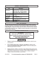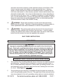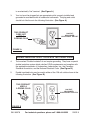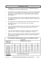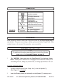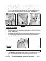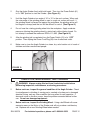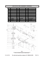
1
4-1/2” ANGLE GRINDER
Model 95578
ASSEMBLY AND OPERATING INSTRUCTIONS
Due to continuing improvements, actual product may differ slightly from the product described herein.
®
3491 Mission Oaks Blvd., Camarillo, CA 93011
Visit our Web site at: http://www.harborfreight.com
TO PREVENT SERIOUS INJURY,
READ AND UNDERSTAND ALL WARNINGS
AND INSTRUCTIONS BEFORE USE.
©
Copyright 2006 by Harbor Freight Tools®. All right reserved. No portion of this
manual or any artwork contained herein may be reproduced in any shape or form
without the express written consent of Harbor Freight Tools.
For technical questions, please call 1-800-444-3353.
PRODUCT SPECIFICATIONS
Item
Electrical
Requirements
Spindle Size
Required
Grinding Wheel Size
(Not Included)
Side Handle
Dimensions
Overall
Dimensions
Net Weight
Description
120 VAC / 60 Hz / 4.2 Amps / 11,000 RPM
Power Cord Type: 18 AWG x 2C / 6’ Long
Power Plug Type: 2-Prong / Polarized
Power Switch Type: Toggle (ON/OFF)
5/8”-11 TPI with 7/8” Arbor Adapter
4-1/2” Diameter
1/4” Thick
7/8” Spindle Hole
4-1/2” Long x 2-1/4” O.D.
10-1/8” Long x 8” Wide x 3-3/4” High
(with Side Handle)
3.5 Pounds
SAVE THIS MANUAL
You will need this manual for the safety warnings and precautions, assembly,
operating, inspection, maintenance and cleaning procedures, parts list and assembly diagram. Keep your invoice with this manual. Write the invoice number
on the inside of the front cover. Keep this manual and invoice in a safe and dry
place for future reference.
GENERAL SAFETY RULES
WARNING!
READ AND UNDERSTAND ALL INSTRUCTIONS
Failure to follow all instructions listed below may result in
electric shock, fire, and/or serious injury.
SAVE THESE INSTRUCTIONS
WORK AREA
1.
Keep your work area clean and well lit. Cluttered benches and dark areas
invite accidents.
2.
Do not operate power tools in explosive atmospheres, such as in the
presence of flammable liquids, gases, or dust. Power tools create sparks
which may ignite the dust or fumes.
3.
Keep bystanders, children, and visitors away while operating a power tool.
Distractions can cause you to lose control. Protect others in the work area from
debris such as chips and sparks. Provide barriers or shields as needed.
Children should not be allowed in the work area.
SKU 95578
For technical questions, please call 1-800-444-3353
PAGE 2
ELECTRICAL SAFETY
4.
Grounded tools must be plugged into an outlet properly installed and
grounded in accordance with all codes and ordinances. Never remove the
grounding prong or modify the plug in any way. Do not use any adapter
plugs. Check with a qualified electrician if you are in doubt as to whether
the outlet is properly grounded. If the tools should electrically malfunction or
break down, grounding provides a low resistance path to carry electricity away
from the user.
5.
Double insulated tools are equipped with a polarized plug (one blade is
wider than the other). This plug will fit in a polarized outlet only one way. If
the plug does not fit fully in the outlet, reverse the plug. If it still does not
fit, contact a qualified electrician to install a polarized outlet. Do not
change the plug in any way. Double insulation
eliminates the need for the
three wire grounded power cord and grounded power supply system.
6.
Avoid body contact with grounded surfaces such as pipes, radiators,
ranges, and refrigerators. There is an increased risk of electric shock if your
body is grounded.
7.
Do not expose power tools to rain or wet conditions. Water entering a power
tool will increase the risk of electric shock.
8.
Do not abuse the Power Cord. Never use the Power Cord to carry the tools
or pull the Plug from an outlet. Keep the Power Cord away from heat, oil,
sharp edges, or moving parts. Replace damaged Power Cords immediately. Damaged Power Cords increase the risk of electric shock.
9.
When operating a power tool outside, use an outdoor extension cord
marked “W-A” or “W”. These extension cords are rated for outdoor use, and
reduce the risk of electric shock.
PERSONAL SAFETY
10.
Stay alert. Watch what you are doing, and use common sense when operating a power tool. Do not use a power tool while tired or under the influence of drugs, alcohol, or medication. A moment of inattention while operating power tools may result in serious personal injury.
11.
Dress properly. Do not wear loose clothing or jewelry. Contain long hair.
Keep your hair, clothing, and gloves away from moving parts. Loose
clothes, jewelry, or long hair can be caught in moving parts.
12.
Avoid accidental starting. Be sure the Power Switch is off before plugging
SKU 95578
For technical questions, please call 1-800-444-3353
PAGE 3
in. Carrying power tools with your finger on the Power Switch, or plugging in
power tools with the Power Switch on, invites accidents.
13.
Remove adjusting keys or wrenches before turning the power tool on. A
wrench or a key that is left attached to a rotating part of the power tool may result
in personal injury.
14.
Do not overreach. Keep proper footing and balance at all times. Proper
footing and balance enables better control of the power tool in unexpected
situations.
15.
Use safety equipment. Always wear eye protection. Dust mask, non-skid
safety shoes, hard hat, or hearing protection must be used for appropriate
conditions.
TOOL USE AND CARE
16.
Use clamps (not included) or other practical ways to secure and support
the workpiece to a stable platform. Holding the work by hand or against your
body is unstable and may lead to loss of control.
17.
Do not force the tool. Use the correct tool for your application. The correct
tool will do the job better and safer at the rate for which it is designed.
18.
Do not use the power tool if the Power Switch does not turn it on or off.
Any tool that cannot be controlled with the Power Switch is dangerous and must
be replaced.
19.
Disconnect the Power Cord Plug from the power source before making any
adjustments, changing accessories, or storing the tool. Such preventive
safety measures reduce the risk of starting the tool accidentally.
20.
Store idle tools out of reach of children and other untrained persons. Tools
are dangerous in the hands of untrained users.
21.
Maintain tools with care. Keep cutting tools sharp and clean. Properly
maintained tools with a sharp cutting edge are less likely to bind and are easier
to control. Do not use a damaged tool. Tag damaged tools “Do not use” until
repaired.
22.
Check for misalignment or binding of moving parts, breakage of parts, and
any other condition that may affect the tool’s operation. If damaged, have
the tool serviced before using. Many accidents are caused by poorly maintained tools.
23.
Use only accessories that are recommended by the manufacturer for your
SKU 95578
For technical questions, please call 1-800-444-3353
PAGE 4
model. Accessories that may be suitable for one tool may become hazardous
when used on another tool.
SERVICE
24.
Tool service must be performed only by qualified repair personnel. Service
or maintenance performed by unqualified personnel could result in a risk of injury.
25.
When servicing a tool, use only identical replacement parts. Follow
instructions in the “Inspection, Maintenance, And Cleaning” section of this
manual. Use of unauthorized parts or failure to follow maintenance instructions
may create a risk of electric shock or injury.
SPECIFIC SAFETY RULES
1.
Always use the Wheel Guard (4) with the Angle Grinder. The Guard protects
the operator from broken grinding wheel fragments.
2.
Hold the tool by its insulated gripping surfaces when performing an operation where the cutting tool may contact hidden wiring or its own cord. Contact with a “live” wire will make exposed metal parts of the tool “live” and shock
the operator.
3.
Maintain labels and nameplates on the Angle Grinder. These carry important
information. If unreadable or missing, contact Harbor Freight Tools for a
replacement.
4.
Always wear ANSI-approved safety impact eye goggles and heavy
work gloves when using the Angle Grinder. Using personal safety
devices reduce the risk for injury. Safety impact eye goggles and heavy
work gloves are available from Harbor Freight Tools.
5.
Maintain a safe working environment. Keep the work area well lit. Make sure
there is adequate surrounding workspace. Always keep the work area free of
obstructions, grease, oil, trash, and other debris. Do not use a power tool in
areas near flammable chemicals, dusts, and vapors. Do not use this product in
a damp or wet location.
6.
WARNING! All accessories for this tool must be rated for at least
11,000 RPM. Grinding wheels and other accessories running over the rated
11,000 RPM speed can fly apart and cause injury.
7.
When using a hand-held power tool, always maintain a firm grip on the tool
with both hands to resist starting torque.
SKU 95578
For technical questions, please call 1-800-444-3353
PAGE 5
8.
Use only 4-1/2” diameter grinding wheels (not included) having a 7/8” center
spindle hole. Never disable or modify the Wheel Guard (4).
9.
Avoid unintentional starting. Make sure you are prepared to begin work
before turning on the Angle Grinder.
10.
Do not force the Angle Grinder. This tool will do the work better and safer at
the speed and capacity for which it was designed. Do not force the rotating
grinding wheel (not included) into the object being ground. Apply moderate
pressure, allowing the grinding wheel to rotate freely without being forced.
11.
WARNING! Never install a carbide tipped or steel circular saw blade
for use on this tool. Never install a wood carving blade, carving disc with
saw chain cutters, or a cutting carving disc on this tool.
12.
For safest operation, it is recommended that only these accessories be
used with this tool: Abrasive cut-off discs and wheels, flap wheels, wire
brushes, and wire wheel brushes.
13.
Never lay this tool down until the rotating grinding wheel has come to a
complete stop. The rotating grinding wheel can grab the surface and pull the
tool out of your control.
14.
Never leave the Angle Grinder unattended when it is plugged into an
electrical outlet. Turn off the tool, and unplug it from the electrical outlet before
leaving.
15.
Always unplug this tool from its electrical outlet before performing inspection, maintenance, or cleaning procedures.
16.
WARNING! Keep hands and fingers away from cutting area and rotating grinding wheel.
17.
Before using the Angle Grinder, always check to make sure the grinding
wheel (not included) is properly mounted and is not cracked or dull.
18.
Industrial applications must follow OSHA guidelines.
19.
The grinding wheel (not included) will become hot while cutting. Allow the
grinding wheel to completely cool before handling.
20.
To avoid accidental injury, always wear heavy duty work gloves when
changing the grinding wheel.
21.
SKU 95578
WARNING! Some dust created by power sanding, sawing, grinding, drilling,
For technical questions, please call 1-800-444-3353
PAGE 6
and other construction activities, contain chemicals known (to the State of California) to cause cancer, birth defects or other reproductive harm. Some examples of these chemicals are: lead from lead-based paints, crystalline silica
from bricks and cement or other masonry products, arsenic and chromium from
chemically treated lumber. Your risk from these exposures varies, depending on
how often you do this type of work. To reduce your exposure to these chemicals:
work in a well ventilated area, and work with approved safety equipment, such as
those dust masks that are specially designed to filter out microscopic particles.
(California Health & Safety Code 25249.5, et seq.)
22.
WARNING! People with pacemakers should consult their physician(s)
before using this product. Operation of electrical equipment in close proximity to
a heart pacemaker could cause interference or failure of the pacemaker.
23.
WARNING! The warnings and cautions discussed in this manual cannot
cover all possible conditions and situations that may occur. It must be understood by the operator that common sense and caution are factors which cannot
be built into this product, but must be supplied by the operator.
SAVE THESE INSTRUCTIONS
GROUNDING
WARNING!
Improperly connecting the grounding wire can result in the risk of electric
shock. Check with a qualified electrician if you are in doubt as to whether the
outlet is properly grounded. Do not modify the power cord plug provided with
the tool. Never remove the grounding prong from the plug. Do not use the
tool if the power cord or plug is damaged. If damaged, have it repaired by
a service facility before use. If the plug will not fit the outlet, have a proper
outlet installed by a qualified electrician.
GROUNDED TOOLS: TOOLS WITH THREE PRONG PLUGS
1.
Tools marked with “Grounding Required” have a three wire cord and three prong
grounding plug. The plug must be connected to a properly grounded outlet. If
the tool should electrically malfunction or break down, grounding provides a low
resistance path to carry electricity away from the user, reducing the risk of electric shock. (See Figure A, next page.)
2.
The grounding prong in the plug is connected through the green wire inside the
cord to the grounding system in the tool. The green wire in the cord must be the
only wire connected to the tool’s grounding system and must never be attached
SKU 95578
For technical questions, please call 1-800-444-3353
PAGE 7
to an electrically “live” terminal. (See Figure A.)
3.
Your tool must be plugged into an appropriate outlet, properly installed and
grounded in accordance with all codes and ordinances. The plug and outlet
should look like those in the following illustration. (See Figure A.)
THIS PRODUCT
DOES NOT
USE A
3-PRONG PLUG
120 VOLT,
GROUNDED,
ELECTRICAL OUTLET
FIGURE A
DOUBLE INSULATED TOOLS: TOOLS WITH TWO PRONG PLUGS
4.
Tools marked “Double Insulated” do not require grounding. They have a special
double insulation system which satisfies OSHA requirements and complies with
the applicable standards of Underwriters Laboratories, Inc., the Canadian
Standard Association, and the National Electrical Code. (See Figure B.)
5.
Double insulated tools may be used in either of the 120 volt outlets shown in the
following illustration. (See Figure B.)
THIS PRODUCT
USES A
2-PRONG PLUG
120 VOLT,
GROUNDED,
ELECTRICAL OUTLETS
FIGURE B
SKU 95578
For technical questions, please call 1-800-444-3353
PAGE 8
EXTENSION CORDS
1.
Grounded tools require a three wire extension cord. Double Insulated tools
can use either a two or three wire extension cord.
2.
As the distance from the supply outlet increases, you must use a heavier gauge
extension cord. Using extension cords with inadequately sized wire causes a
serious drop in voltage, resulting in loss of power and possible tool damage.
(See Figures C.)
3.
The smaller the gauge number of the wire, the greater the capacity of the cord.
For example, a 14 gauge cord can carry a higher current than a 16 gauge cord.
(See Figures C.)
4.
When using more than one extension cord to make up the total length, make
sure each cord contains at least the minimum wire size required.
(See Figures C.)
5.
If you are using one extension cord for more than one tool, add the nameplate
amperes and use the sum to determine the required minimum cord size.
(See Figures C.)
6.
If you are using an extension cord outdoors, make sure it is marked with the
suffix “W-A” (“W” in Canada) to indicate it is acceptable for outdoor use.
7.
Make sure your extension cord is properly wired and in good electrical condition.
Always replace a damaged extension cord or have it repaired by a qualified
electrician before using it.
8.
Protect your extension
cords from
sharp
objects,
excessive
heat, and
damp or
RECOMMENDED
MINIMUM
WIRE
GAUGE
FOR
EXTENSION
CORDS*
wet areas.
(120 VOLT)
FIGURE C
SKU 95578
* Based on limiting the line voltage drop
to five volts at 150% of the rated amperes.
For technical questions, please call 1-800-444-3353
PAGE 9
SYMBOLOGY
FIGURE D
UNPACKING
When unpacking, check to make sure all the parts shown on the Parts List on page 14
are included. If any parts are missing or broken, please call Harbor Freight Tools at the
number shown on the cover of this manual as soon as possible.
ASSEMBLY INSTRUCTIONS
NOTE:
For additional information regarding the parts listed in the following
pages, refer to the Assembly Diagram on page 14.
1.
CAUTION! Always make sure the PowerSwitch (41) for the Angle Grinder
is in its “OFF” position and the tool is unplugged from its electrical outlet prior to
assembling the tool, adding any accessories, or making adjustments to the tool.
To Install A Grinding Wheel:
1.
Unscrew and remove the Outer Flange Nut (1) from the Spindle (7).
(See Figure E, next page.)
2.
Insert the Grinding Wheel (not included) onto the Spindle (7), making sure to
SKU 95578
For technical questions, please call 1-800-444-3353
PAGE 10
install the convex (rounded outward) side of the Grinding Wheel toward the
Spindle (7). (See Figure E.)
3.
Screw the Outer Flange Nut (1) onto the Spindle (7). Depress and hold the Lock
Pin (22) to keep the Spindle from turning. Then, use the provided Wrench (51)
to firmly tighten the Outer Flange Nut onto the Spindle. (See Figure E.)
A
B
C
GRINDING
WHEEL
LOCK PIN
(22)
WRENCH
(51)
SPINDLE
(7)
OUTER
FLANGE
NUT
(1)
OUTER
FLANGE
NUT
(1)
FIGURE E
To Attach The Side Handle:
1.
The Side Handle (18) may be attached to either the left or right side of the Angle
Grinder. (See Figure F.)
2.
To attach the Side Handle (18) to the Angle Grinder, screw the Handle firmly into
the threaded mounting hole located on either the left or right side of the Shell
Head (23). (See Figure F.)
SIDE
HANDLE
(18)
SHELL
HEAD
(23)
FIGURE F
OPERATING INSTRUCTIONS
1.
WARNING! Make sure the Power Switch (41) of the Angle Grinder is in its
“OFF” position before connecting the Power Cord/Plug (50) to a 120 volt,
grounded, electrical outlet.
SKU 95578
For technical questions, please call 1-800-444-3353
PAGE 11
2.
Grip the Angle Grinder firmly with both hands. Then turn the Power Switch (41)
to its “ON” position to start the Grinder. (See Figure G.)
3.
Hold the Angle Grinder at an angle of 10 to 15 to the work surface. When only
the outer edge of the grinding wheel is used, a rough cut surface will result. If
the grinding wheel is pressed flat against the workpiece, the grinding action will
be irregular or bumpy and the tool will be difficult to control. (See Figure G.)
4.
Do not force the rotating grinding wheel into the workpiece. Apply moderate
pressure, allowing the grinding wheel to rotate freely without being forced. Do
not attempt to exceed the maximum RPM of 11,000. (See Figure G.)
5.
After the grinding job is completed, turn the Power Switch (41) to its “OFF”
position. Then unplug the Power Cord/Plug (50) from its electrical outlet.
6.
Make sure to store the Angle Grinder in a clean, dry, safe location out of reach of
children and other unauthorized people.
o
o
POWER SWITCH
(41)
FIGURE G
INSPECTION, MAINTENANCE, AND CLEANING
1.
WARNING! Always unplug this tool from its electrical outlet before
performing inspection, maintenance, or cleaning procedures.
2.
Before each use, inspect the general condition of the Angle Grinder. Check
for misalignment or binding of moving parts, cracked or broken parts, damaged
electrical wiring, and any other condition that may affect its safe operation. If
abnormal noise or vibration occurs, have the problem corrected before further
use. Do not use damaged equipment.
3.
Before each use, inspect the Grinding Wheel. Using a dull Wheel will cause
excessive wear on the Motor of the Grinder and will not produce a satisfactory
FIGURE F
cut. Replace with a new Grinding Wheel when needed.
SKU 95578
For technical questions, please call 1-800-444-3353
PAGE 12
4.
To clean or replace the Carbon Brushes (38): It may become necessary to
clean or replace the two Carbon Brushes when the Motor performance decreases, or stops working completely. The Carbon Brushes are located on
each side of the Motor Housing (40). To do so, remove the two Brush Holder
Covers (37). Then, remove the two Carbon Brushes from the Brush Holders
(39). If the Carbon Brushes are worn down more than 1/2, replace both Carbon
Brushes. If, however, the Carbon Brushes are just dirty they may be cleaned by
rubbing them with a pencil eraser; if only cleaning is required, clean and place
brushes in the same position as they were orginally in. When installing the Car
bon Brushes, make sure the carbon portion of the Carbon Brushes contact the
Motor Armature (30), and the springs face away from the Motor. Also, make sure
the springs operate freely. After cleaning or replacement, replace the Brush
Holder Covers.
NOTE: New Carbon Brushes tend to arc or spark when first used until they
wear and conform to the Motor’s Armature.
(See Assy. Diagram.)
5.
To clean the exterior parts of the Angle Grinder, use only a clean cloth and
mild detergent. Then dry. Do not immerse any electrical part of the tool in
any liquids.
6.
Make sure to store the Angle Grinder in a clean, dry, safe location out of reach of
children and other unauthorized people.
7.
CAUTION! All maintenance, service, or repairs not mentioned in this
manual must only be performed by a qualified service technician.
TROUBLESHOOTING
Problem
Angle Grinder will not turn on.
Possible Solution
1. Make sure tool is plugged into a working 120 volt, grounded, electrical outlet.
2. Make sure the Power Switch is in its “ON” position.
3. Unplug tool from its electrical outlet. Check both Carbon Brushes for
excessive wear or excessive dirt and debris. If necessary, replace or
clean both Carbon Brushes.
Angle Grinder runs, but a rough
cut surface results when grinding
the workpiece.
Angle Grinder runs, but the grinding
action is irregular or bumpy and
the tool is difficult to control.
The Power Switch does not turn
the Angle Grinder off.
SKU 95578
4. Have a qualified service technician check out the tool.
1. Make sure to hold the tool at an angle of 10 to 15 degrees to the work
surface.
2. Check the grinding wheel for dullness, cracks, and other damage.
If necessary, replace the grinding wheel.
1. Make sure to hold the tool at an angle of 10 to 15 degrees to the work
surface.
1. Immediately disconnect the Power Cord/Plug from its electrical outlet and
discontinue using the tool. Then have a qualified service technician check out
the tool.
For technical questions, please call 1-800-444-3353
PAGE 13
PARTS LIST AND ASSEMBLY DIAGRAM
Part #
1
2
3
4
5
6
7
8
9
10
11
12
13
14
15
16
17
Description
Outer Flange Nut
Spring Washer
Inner Flange
Wheel Guard
Screw
Nut
Spindle
Woodruff Key
Screw
Spring Washer
Flat Washer
Gearbox Bottom Cover
Bearing 60201
Locking Ring
Ring Gear
Locking Ring
Bearing
Part #
18
19
20
21
22
23
24
25
26
27
28
29
30
31
32
33
34
Description
Side Handle
Screw
Keeper
Lock Spring
Lock Pin
Shell Head
Pinion Gear
Bearing 6018
Gearbox Back Cover
Spring Washer
Screw
Woodruff Key
Armature
Bearing 6018
Bearing Cover
Bolt
Stator
Part #
35
36
37
38
39
40
41
42
43
44
45
46
47
48
49
50
51
Description
Spring
Wind Shield Ring
Brush Holder Cover
Carbon Brush (#100, Qty. 2)
Brush Holder (#100)
Motor Housing
Power Switch
Switch Mount
Screw
Switch
End Cap Housing
Screw
Sheath (#115A)
Power Cord Bracket
Self Tapping Screw
Power Cord/Plug
Wrench
NOTE:
Some parts are listed and shown for illustration purposes only,
and are not available individually as replacement parts.
SKU 95578
For technical questions, please call 1-800-444-3353
PAGE 14
IMPORTANT WARRANTY INFORMATION
LIMITED 90 DAY
WARRANTY
Harbor Freight Tools Co. makes every effort to assure that its products meet high quality and durability standards,
and warrants to the original purchaser that this product is free from defects in materials and workmanship for
the period of ninety days from the date of purchase. This warranty does not apply to damage due directly or
indirectly, to misuse, abuse, negligence or accidents, repairs or alterations outside our facilities, or to lack of
maintenance. We shall in no event be liable for death, injuries to persons or property, or for incidental, contingent,
special or consequential damages arising from the use of our product. Some states do not allow the exclusion or
limitation of incidental or consequential damages, so the above limitation of exclusion may not apply to you. THIS
WARRANTY IS EXPRESSLY IN LIEU OF ALL OTHER WARRANTIES, EXPRESS OR IMPLIED, INCLUDING
THE WARRANTIES OF MERCHANTABILITY AND FITNESS.
To take advantage of this warranty, the product or part must be returned to us with transportation charges prepaid.
Proof of purchase date and an explanation of the complaint must accompany the merchandise. If our inspection
verifies the defect, we will either repair or replace the product at our election or we may elect to refund the purchase
price if we cannot readily and quickly provide you with a replacement. We will return repaired products at our
expense, but if we determine there is no defect, or that the defect resulted from causes not within the scope of
our warranty, then you must bear the cost of returning the product.
This warranty gives you specific legal rights and you may also have other rights which vary from state to state.
3491 Mission Oaks Blvd. • PO Box 6009 • Camarillo, CA 93011 • (800) 444-3353
SKU 95578
For technical questions, please call 1-800-444-3353
PAGE 15