1
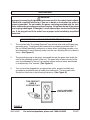
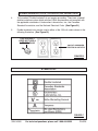
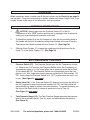
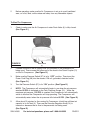
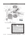
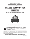
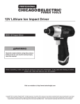
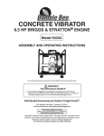
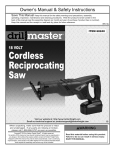
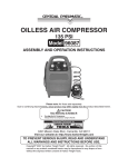
OILLESS AIR COMPRESSOR
8 GALLON CAPACITY
Model 94355
ASSEMBLY AND OPERATING INSTRUCTIONS
Due to continuing improvements,
actual product may differ slightly
from the product described herein.
®
TO PREVENT SERIOUS INJURY,
READ AND UNDERSTAND ALL WARNINGS
AND INSTRUCTIONS BEFORE USE.
3491 Mission Oaks Blvd., Camarillo, CA 93011
Visit our Web site at: http://www.harborfreight.com
Copyright© 2006 by Harbor Freight Tools®. All rights reserved. No portion of this
manual or any artwork contained herein may be reproduced in any shape or form
without the express written consent of Harbor Freight Tools.
For technical questions, please call 1-800-444-3353.
PRODUCT SPECIFICATIONS
Electrical Requirements
Operating Air Pressure
Air Flow
Air Tank Capacity
Outlet Thread
Pressure Gauge Measures
Additional Features
Unit Weight
120 V / 60 Hz / 13 Amp / 2 HP Rated, 3 HP Peak
Power Cord Type: 16 Gauge x 3 C x 6’ Long
Power Plug Type: 3-Prong, Grounded
Fuse Size: 15 AMP Buss Fuse
Switch Type: Rotary On/Off Switch
Pressure On: 85 PSI / Pressure Off: 125 PSI
6.0 CFM @ 40 PSI / 4 CFM @ 90 PSI
8 Gallons
1/4" – 18 NPT
0 ~ 230 PSI in 20 PSI Increments / 0 ~ 16 KG/CM² in 2 BAR Increments
Thermal Overload Protection / Steel Tube Handle
Rubber Wheels / Brass Valve Tank Drain / Single Cylinder Pump
51 Pounds
235309
SAVE THIS MANUAL
You will need this manual for the safety warnings and precautions, assembly, operating,
inspection, maintenance and cleaning procedures, parts list and assembly diagram. Keep
your invoice with this manual. Write the invoice number on the inside of the front cover.
Keep this manual and invoice in a safe and dry place for future reference.
GENERAL SAFETY RULES AND PRECAUTIONS
WARNING!
READ AND UNDERSTAND ALL INSTRUCTIONS
Failure to follow all instructions listed below may result in
electric shock, fire, and/or serious injury.
SAVE THESE INSTRUCTIONS
SAFE OPERATION
1.
RISK OF FIRE OR EXPLOSION:
Do not spray flammable liquid in a confined area or towards a hot surface.
Spray area must be well ventilated.
Do not smoke while spraying or spray where spark or flame is present.
SKU 94355
For technical questions, please call 1-800-444-3353
REV 11/06
PAGE 2
2.
ARCING PARTS:
Keep compressor at least 20 feet away from explosive vapors, such as when
spraying with a spray gun.
3.
IF CONNECTED TO A CIRCUIT PROTECTED BY FUSES:
Use time delay (Marked D) fuses with this item.
Connect to a dedicated power sources (see serial plate for proper voltage).
Check oil level in the compressor before each use and fill accordingly.
4.
RISK OF BURSTING:
Do not adjust the regulator to result in output pressure greater than marked
maximum pressure of attachment (air tools, etc).
5.
RISK OF INJURY:
Do not direct air stream at anyone’s body.
Do not use compressed air for breathing.
Unplug the power cord and drain all air pressure from the tank before servicing
and after each use.
Always wear ANSI-approved eye protection.
Do not operate with supplied guards removed or damaged.
6.
RISK OF ELECTRIC SHOCK:
Do not expose to rain, store this item indoors in a dry location.
WORK AREA
1.
Keep your work area clean and well lit. Cluttered benches and dark areas
invite accidents.
2.
Do not operate power tools in explosive atmospheres, such as in the
presence of flammable liquids, gases, or dust. Power tools create
sparks which may ignite the dust or fumes.
3.
Keep bystanders, children, and visitors away while operating a power tool.
Distractions can cause you to lose control. Protect others in the work area from
debris such as chips and sparks. Provide barriers or shields as needed.
SKU 94355
For technical questions, please call 1-800-444-3353
PAGE 3
PERSONAL SAFETY
1.
Stay alert. Watch what you are doing, and use common sense when
operating a power tool. Do not use a power tool while tired or under the
influence of drugs, alcohol, or medication. A moment of inattention while
operating power tools may result in serious personal injury.
2.
Dress properly. Do not wear loose clothing or jewelry. Contain long hair.
Keep your hair, clothing, and gloves away from moving parts. Loose
clothes, jewelry, or long hair can be caught in moving parts.
3.
Avoid accidental starting. Be sure the Pressure Switch (57) is in its “OFF”
position before moving the Compressor and before performing any service,
maintenance, or cleaning procedures on the unit.
4.
Remove adjusting keys or wrenches before turning the Compressor on. A
wrench or a key that is left attached to a rotating part of the machine may result
in personal injury.
5.
Do not overreach. Keep proper footing and balance at all times. Proper
footing and balance enables better control of the power tool in unexpected
situations.
6.
Use safety equipment. Always wear eye protection. Always wear
ANSI-approved safety impact goggles when using this product. ANSIapproved hearing protection must also be used.
TOOL USE AND CARE
1.
Do not force the tool. Use the correct tool for your application. The correct
tool will do the job better and safer at the rate for which it is designed.
2.
Do not use the Compressor if the Pressure Switch (57) does not turn it on
or off. Any tool that cannot be controlled with its pressure switch is dangerous
and must be replaced.
3.
Store idle tools out of reach of children and other untrained persons. Tools
are dangerous in the hands of untrained users.
4.
Maintain tools with care. Properly maintained tools with a sharp cutting edge
are less likely to bind and are easier to control. Do not use a damaged tool. Tag
damaged tools “Do not use” until repaired.
SKU 94355
For technical questions, please call 1-800-444-3353
PAGE 4
5.
Check for misalignment or binding of moving parts, breakage of parts, and
any other condition that may affect the tool’s operation. If damaged, have
the tool serviced before using. Many accidents are caused by poorly
maintained tools.
6.
Use only accessories that are recommended by the manufacturer for your
model. Accessories that may be suitable for one tool may become hazardous
when used on another tool.
SERVICE
1.
Tool service must be performed only by qualified repair personnel. Service
or maintenance performed by unqualified personnel could result in a risk of injury.
2.
When servicing a tool, use only identical replacement parts. Follow
instructions in the “Inspection, Maintenance, And Cleaning” section of this
manual. Use of unauthorized parts or failure to follow maintenance instructions
may create a risk of electric shock or injury.
SPECIFIC SAFETY RULES AND PRECAUTIONS
1.
Maintain labels and nameplates on the Air Compressor. These carry
important information. If unreadable or missing, contact Harbor Freight Tools for a
replacement.
2.
DANGER! This Air Compressor is NOT equipped with and should not be
used “as is” to supply breathing quality air. For any application of air for human
consumption, you must fit the Air Compressor with suitable inline safety and
alarm equipment (not included). This additional equipment is necessary to
properly filter and purify the air to meet minimal specifications for Grade D
breathing as described in Compressed Gas Association Commodity Specification
G 7.1-1966, OSHA 29 CFR 1910. 134, and/or Canadian Standards Associations
(CSA).In the event the Air Compressor is used for the purpose of breathing air
application and proper inline safety and alarm equipment is not simultaneously
used, existing warranties are void, and Harbor Freight Tools disclaims any liability
whatsoever for any loss, personal injury, or damage.
3.
Make sure all tools and equipment used with the Air Compressor are rated
to the appropriate capacity. Do not use any tool or equipment that does not
operate from 85 PSI to 125 PSI.
4.
Drain the Air Compressor every day. Do not allow excessive moisture to build
up inside the Air Compressor. Do not open the water Drain Valve (4) with more
than 10 PSI of air pressure in the Compressor.
SKU 94355
For technical questions, please call 1-800-444-3353
PAGE 5
5.
Avoid injury. Never direct compressed air at people or animals.
6.
Make sure the Air Compressor is located on a flat, level, sturdy surface
capable of supporting the weight of the Compressor and any additional
tools and equipment.
7.
Industrial applications must follow OSHA guidelines.
8.
Never stand on the Air Compressor. Serious injury could result if the
Compressor is tipped.
9.
Never leave the Air Compressor unattended when it is plugged in and
running. Turn off the Compressor, and unplug the unit before leaving.
10.
Do not allow children and other unauthorized people to handle or play with
the Air Compressor.
11.
Do not move or transport the Compressor if the unit is under pressure.
12.
Do not force the Compressor. This tool will do the work better and safer at
the speed and capacity for which it was designed.
13.
This Compressor will automatically shut off on overload or under excessive
heat. Should this occur, turn the Pressure Switch (57) to its “OFF” position. Wait
until the Compressor cools. Then, turn the Pressure Switch to its “ON” position
to resume work.
14.
WARNING! This product contains brass, which is a chemical known to the
State of California to cause cancer and birth defects and other reproductive
harm. (California Health & Safety Code 25249.5, et seq.)
15.
WARNING! People with pacemakers should consult their physician(s)
before using this product. Operation of electrical equipment in close proximity to
a heart pacemaker could cause interference to or failure of the pacemaker.
16.
WARNING! The warnings and precautions discussed in this manual cannot
cover all possible conditions and situations that may occur. It must be under
stood by the operator that common sense and caution are factors which cannot
be built into this product, but must be supplied by the operator.
SAVE THESE INSTRUCTIONS
SKU 94355
For technical questions, please call 1-800-444-3353
PAGE 6
GROUNDING
WARNING!
Improperly connecting the grounding wire can result in the risk of electric shock.
Check with a qualified electrician if you are in doubt as to whether the outlet is
properly grounded. Do not modify the power cord plug provided with the tool.
Never remove the grounding prong from the plug. Do not use the tool if the power
cord or plug is damaged. If damaged, have it repaired by a service facility before
use. If the plug will not fit the outlet, have a proper outlet installed by a qualified
electrician.
GROUNDED TOOLS: TOOLS WITH THREE PRONG PLUGS
1.
Tools marked with “Grounding Required” have a three wire cord and three prong
grounding plug. The plug must be connected to a properly grounded outlet. If
the tool should electrically malfunction or break down, grounding provides a low
resistance path to carry electricity away from the user, reducing the risk of electric
shock. (See Figure A.)
2.
The grounding prong in the plug is connected through the green wire inside the
cord to the grounding system in the tool. The green wire in the cord must be the
only wire connected to the tool’s grounding system and must never be attached
to an electrically “live” terminal. (See Figure A.)
3.
Your tool must be plugged into an appropriate outlet, properly installed and
grounded in accordance with all codes and ordinances. The plug and outlet
should look like those in the following illustration. (See Figure A.)
THIS PRODUCT
USES A
3-PRONG PLUG
120 VOLT, GROUNDED,
ELECTRICAL OUTLET
FIGURE A
SKU 94355
For technical questions, please call 1-800-444-3353
PAGE 7
DOUBLE INSULATED TOOLS: TOOLS WITH TWO PRONG PLUGS
4.
Tools marked “Double Insulated” do not require grounding. They have a special
double insulation system which satisfies OSHA requirements and complies with
the applicable standards of Underwriters Laboratories, Inc., the Canadian
Standard Association, and the National Electrical Code. (See Figure B.)
5.
Double insulated tools may be used in either of the 120 volt outlets shown in the
following illustration. (See Figure B.)
THIS PRODUCT
DOES NOT USE A
2-PRONG PLUG
120 VOLT, GROUNDED,
ELECTRICAL OUTLETS
FIGURE B
SYMBOLOGY
FIGURE C
SKU 94355
For technical questions, please call 1-800-444-3353
PAGE 8
UNPACKING
When unpacking, check to make sure all the parts shown on the Parts List on page 14
are included. If any parts are missing or broken, please call Harbor Freight Tools at the
number shown on the cover of this manual as soon as possible.
ASSEMBLY INSTRUCTIONS
1.
CAUTION! Always make sure the Pressure Switch (57) of the Air
Compressor is in its “OFF” position and the unit is unplugged from its electrical
outlet prior to performing any assembly on this unit.
2.
To attach the Handle (9) to the Air Compressor, align the four mounting holes in
the Handle with the four threaded mounting holes located at the rear of the unit.
Then secure the Handle in place with four Screws (7). (See Page 16)
3.
Slide the Quick Coupler (11) towards the compressor body and insert the Air
Hose (71) to the Quick Coupler (11). (See Page 16)
AIR COMPRESSOR CONTROLS
1.
Pressure Switch (57): The Pressure Switch turns the Air Compressor on and
off. When in the “ON” position, the Pressure Switch allows the Compressor to
automatically adjust to its “run” stage when the air pressure inside the Air Tank
(3) falls below 85 PSI. The Pressure Switch also automatically turns the Com
pressor to its “idle” stage when the air pressure inside the Air Tank reaches 125
PSI. Always keep the Pressure Switch in its “OFF” position when the unit is not
in use. (See Figure D, next page.)
2.
Safety Valve (10): If the Pressure Switch (57) does not shut down the Motor of
the Air Compressor when the pressure reaches 125 PSI, the Safety Valve will
automatically pop open to prevent over-pressurization. To operate manually, pull
the ring on the Safety Valve to relieve air pressure in the Air Tank (3).
(See Figure D, next page.)
3.
Tank Pressure Gauge (13): The Tank Pressure Gauge measures the pressure
level of the air stored in the Air Tank (3), and is not adjustable by the operator.
(See Figure D.)
SKU 94355
For technical questions, please call 1-800-444-3353
PAGE 9
4.
Pressure Regulator Knob (14): The Pressure Regulator Knob enables the
operator to adjust output pressure to the pneumatic tool being used. To increase
the amount of air pressure to the tool, turn the Pressure Regulator Knob clock
wise. To decrease the amount of air pressure to the tool, turn the Pressure
Regulator Knob counterclockwise. (See Figure D.)
5.
Tool Pressure Gauge (13): The Tool Pressure Gauge measures the pressure
level of air flowing to the pneumatic tool being used, and is adjustable using the
Pressure Regulator Knob (14). (See Figure D.)
6.
Quick Coupler (11): The Quick Coupler connects to the air output hose which,
in turn, connects to the pneumatic tool being used. To connect an air hose, push
in on the Quick Coupler. To disconnect the air hose, pull back on the Quick
Coupler collar. (See Figure D.)
PRESSURE
REGULATOR
KNOB
(14)
TOOL
TANK
PRESSURE
PRESSURE
GAUGE
GAUGE
(13)
(13)
PRESSURE SWITCH
(57)
QUICK COUPLER
(11)
SAFETY VALVE
(10)
FIGURE D
OPERATING INSTRUCTIONS
1.
CAUTION! Always make sure the Pressure Switch (57) of the Air
Compressor is in its “OFF” position and the unit is unplugged from its electrical
outlet prior to performing any service, maintenance, or changing accessories on
the Compressor.
SKU 94355
For technical questions, please call 1-800-444-3353
PAGE 10
2.
Before operating, make sure the Air Compressor is set up in a well ventilated
area, on a flat, level, solid surface well away from any flammable objects.
To Start The Compressor:
1.
Check to make sure the Air Compressor’s water Drain Valve (4) is fully closed.
(See Figure E.)
FIGURE E
DRAIN VALVE
(4)
2.
Connect one end of the air supply hose (not included) to the pneumatic tool
being used. Then connect the other end of the hose to the Quick Coupler (11)
on the Air Compressor. (See Figure D.)
3.
Make sure the Pressure Switch (57) is in its “OFF” position. Then insert the
Power Cord Plug (66) into the nearest 120 volt, grounded, electrical outlet.
(See Figure D.)
3.
Turn the Pressure Switch (57) to its “ON” position. (See Figure D.)
4.
NOTE: The Compressor will automatically begin to run when the air pressure
reaches 85 PSI as indicated on the Tank Pressure Gauge (13) . When the
maximum air pressure (125 PSI) is reached, the Compressor will automatically
switch to idle and the Compressor will stop operating. The Compressor will
automatically restart when the air pressure falls below 85 PSI. (See Figure D.)
5.
Allow about 15 minutes for the running Air Compressor to build up sufficient air
capacity in its Air Tank (3). Then use the Pressure Regulator Knob (14) to
increase or decrease the air flow to the pneumatic tool being used.
(See Figure D.)
SKU 94355
For technical questions, please call 1-800-444-3353
PAGE 11
6.
When finished using the Air Compressor, turn its Pressure Switch (57) to its
“OFF” position. Then, unplug the unit from its electrical outlet. (See Figure D.)
7.
Pull the ring on the Safety Valve (10) to release any remaining compressed air in
the Air Tank (3) of the Compressor. (See Figure D.)
8.
Squeeze the trigger of the pneumatic tool being used to release any remaining
compressed air in the air hose and tool. Then disconnect the air hose from the
tool and from the Air Compressor.
9.
Slightly unscrew (no more than 4 turns) the water Drain Valve (4) to release any
water condensation from the Air Tank (3). Then, retighten the Drain Valve.
(See Figure E.)
10.
Allow the Air Compressor to completely cool down. Then make sure to store the
unit in a clean, dry, safe location out of reach of children and other unauthorized
people.
ATTENTION!
This air compressor is designed for intermittent use. To help prolong the life of
your air compressor it is recommended to allow a 30 minute cooling time between
every half an hour of use. This product is not under warranty for Commerical
purposes.
INSPECTION, MAINTENANCE, AND CLEANING
1.
CAUTION! Always make sure the Pressure Switch (57) of the Air Compressor is in its “OFF” position and the unit is unplugged from its electrical outlet prior
to performing any service, maintenance, or cleaning of the Compressor.
2.
Before each use, inspect the general condition of the Air Compressor. Check for
loose screws, misalignment or binding of moving parts, cracked or broken parts,
damaged electrical wiring, loose air fittings, and any other condition that may
affect the safe operation of the Compressor. If abnormal noise or vibration occurs,
have the problem corrected before further use.
Do not use damaged equipment.
3.
After each use, open the water Drain Valve (4) under the Air Tank (3) to drain
out the moisture. (See Figure E.)
SKU 94355
For technical questions, please call 1-800-444-3353
PAGE 12
4.
To clean, wipe with a damp cloth, using a mild detergent. Never use solvents
such as thinner, alcohol, trichloroethylene, etc. to clean the Air Compressor.
5.
To replace the Motor Carbon Brushes: It may become necessary at sometime
to replace or clean the two Carbon Brushes (68) when the Motor performance
decreases, or stops working completely. The Carbon Brushes are located on
each side of the Motor Cover (46). To replace the Carbon Brushes, remove
the two Brush Holder Covers. Remove the Brush Caps. Then, remove the two
the two Carbon Brushes from the two Brush Holders. If the Carbon Brushes are
worn down more than 1/2, replace both Carbon Brushes. If, however, the Carbon
Brushes are just dirty they may be cleaned by rubbing them with a pencil eraser.
When installing the Carbon Brushes, make sure the carbon portion of the Carbon
Brushes contact the Motor’s Rotor and that the springs face away from the Motor.
Also, make sure the springs operate freely. After replacement or cleaning, replace
the two Brush Holder Covers. NOTE: New Carbon Brushes tend to arc or spark
when first used until they wear and conform to the Motor’s Rotor. (See Assy.
Diagram.)
6.
To replace the Fuse: An indicator of a blown Fuse (28) is if its wire strand within
is burnt in half. When replacing the Fuse, make sure to install a new 15 AMP
Buss Fuse.
7.
Always store the Air Compressor in a clean, dry, safe location out of reach of
children and other unauthorized people.
8.
CAUTION! All maintenance, service, or repairs not mentioned in this
manual must only be performed by a qualified service technician.
PLEASE READ THE FOLLOWING CAREFULLY
THE MANUFACTURER AND/OR DISTRIBUTOR HAS PROVIDED THE PARTS LIST AND ASSEMBLY
DIAGRAM IN THIS MANUAL AS A REFERENCE TOOL ONLY. NEITHER THE MANUFACTURER OR
DISTRIBUTOR MAKES ANY REPRESENTATION OR WARRANTY OF ANY KIND TO THE BUYER THAT HE
OR SHE IS QUALIFIED TO REPLACE ANY PARTS OF THE PRODUCT. IN FACT, THE MANUFACTURER
AND/OR DISTRIBUTOR EXPRESSLY STATES THAT ALL REPAIRS AND PARTS REPLACEMENTS SHOULD
BE UNDERTAKEN BY CERTIFIED AND LICENSED TECHNICIANS, AND NOT BY THE BUYER. THE BUYER
ASSUMES ALL RISKS AND LIABILITY ARISING OUT OF HIS OR HER REPAIRS TO THE ORIGINAL
PRODUCT OR REPLACEMENT PARTS THERETO, OR ARISING OUT OF HIS OR HER INSTALLATION OF
REPLACEMENT PARTS THERETO.
SKU 94355
For technical questions, please call 1-800-444-3353
PAGE 13
TROUBLESHOOTING
Problem
Circuit breaker/fuse trip often.
Overheating.
Possible Solution
1. Do not use an extension cord.
Link additional air hoses together
to acquire additional length.
2. Restricted air passages.
2. Check all air passages for clogs.
3. Back pressure in pump head.
3. Have a qualified service technician
replace check valve and/or
pressure switch bleeder valve.
1. Relocate air compressor to an area
with cool, dry, well circulated air.
1. Poor ventilation.
Motor stalls.
2. Dirty cooling surfaces.
2. Clean all cooling surfaces of pump
and motor thoroughly.
3. Leaking valve.
3. Have a qualified service technician
replace worn parts and
re-assemble with new seals.
1. Do not use an extension cord.
Link additional air hoses together
to acquire additional length.
1. Low voltage.
Pressure relief valve opens.
Motor will not run.
Possible Cause
1. Excessive wire length causes
voltage to drop too much.
2. Defective pressure switch
bleeder valve.
2. Have a qualified service technician
replace defective pressure switch
bleeder valve.
1. Air tank pressure has exceeded
normal operating pressure.
1. Have a qualified service technician
replace pressure switch.
2. Pressure switch is stuck.
2. Have a qualified service technician
replace pressure switch.
1. Motor will automatically start when
air tank pressure drops below 85
PSI pressure of air tank.
1. Air tank pressure exceeds preset
pressure switch limit.
2. Motor overload protection has been
Tripped.
3. Air compressor attached to an
extension cord.
2. Replace blown fuse or reset circuit
breaker. Do not use a fuse or
circuit breaker with higher rating
than specific for your circuit
branch. Check for proper fuse;
15 AMP Buss fuse is acceptable.
Do not use an extension cord.
Link additional air hoses together
to acquire additional length.
Disconnect other applications from
circuit.
Operate air compressor on a dedicated circuit.
Bleed line by moving pressure
switch lever to OFF position before
restarting. If bleeder valve does
not open, replace bleeder valve.
Have a qualified service technician
clean or replace motor.
SKU 94355
For technical questions, please call 1-800-444-3353
PAGE 14
PARTS LIST
Part #
1
2
3
4
5
6
7
8
9
10
11
12
13
14
15
16
17
18
19
20
21
22
23
24
25
26
27
28
29
30
31
32
33
34
35
Description
Screw (M6 x 25)
Rubber Support
Air Tank
Drain Valve
Wheel
Nut (M8 x 40)
Screw (M6 x35)
Kit
Handle
Safety Valve
Quick Coupler
Screw (ST4 x 20)
Tank/Tool Pressure Gauge
Pressure Regulator Knob
1/4” Air Nozzle
1/4" x 1/4" Tie-In
1/4" x 1/4” Fix Ring
Copper Nut
Copper Tube
Screw (M10 x 25)
Bearing (6203)
Connecting Rod
Piston Ring
Back Plate
Hex Screw (M6 x 15)
Copper Tube
1/2" x 1/2" Fix Ring
Fuse
Upper Cover
1/2" x 1/2" Plug
Hex Bolt (M6 x 105)
Cylinder Head
Exhaust
Washer
Head Gasket
Qty
1
1
1
1
2
2
4
1
1
1
1
13
2
1
1
1
1
2
1
1
3
1
1
1
1
1
1
1
1
1
4
1
1
1
1
Part #
36
37
38
39
40
41
42
43
44
45
46
47
48
49
50
51
52
53
54
55
56
57
58
59
60
61
62
63
64
65
66
67
68
69
70
71
Description
Outlet Valve Support
Valve Plate
Inlet Valve Plate
Washer
Cylinder
Hex Screw (M6 x 35)
Washer
Strap Wheel
Stator
Armature
Cover
Hex Screw (M5 x 95)
Connection Plate
Fan
Fan Cover
Valve
Connector
C5 Washer
Air Nozzle Plug
Screw (M5 x 10)
Ground Wire
Air Pressure Switch
Strap
Transmission Shaft
Eccentric Wheel
Motor Support
Stator Washer
Over Heat Sensor
Screw (ST4.2 x 15)
Strain Relief
Power Cord/Plug
O-Ring (6000)
Carbon Brush Assembly
Screw (ST4 x 10)
Lower Cover
Air Hose
Qty
1
1
1
1
1
3
3
1
1
1
1
2
2
1
1
1
1
2
2
2
2
1
1
1
1
1
1
1
1
1
1
2
2
4
1
1
NOTE:
Some parts are listed and shown for illustration purposes only,
and are not available individually as replacement parts.
SKU 94355
For technical questions, please call 1-800-444-3353
PAGE 15
ASSEMBLY DIAGRAM
28: Fuse Not Shown.
NOTE:
Some parts are listed and shown for illustration purposes only,
and are not available individually as replacement parts.
LIMITED 1 YEAR/
90 DAY WARRANTY
WARANTY
Harbor Freight Tools Co. makes every effort to assure that its products meet high quality and durability standards,
and warrants to the original purchaser that for a period of ninety days from date of purchase that the motor is
free of defects in materials and workmanship. Harbor Freight Tools also warrants to the original purchaser, for
a period of one year from date of purchase, that all other par ts and components of the product are free from
defects in materials and workmanship. This warranty does not apply to damage due directly or indirectly, to
misuse, abuse, negligence or accidents, repairs or alterations outside our facilities, or to lack of maintenance.
We shall in no event be liable for death, injuries to persons or property, or for incidental, contingent, special or
consequential damages arising from the use of our product. Some states do not allow the exclusion or limitation
of incidental or consequential damages, so the above limitation of exclusion may not apply to you. THIS
WARRANTY IS EXPRESSLY IN LIEU OF ALL OTHER WARRANTIES, EXPRESS OR IMPLIED, INCLUDING
THE WARRANTIES OF MERCHANTABILITY AND FITNESS.
To take advantage of this warranty, the product or part must be returned to us with transportation charges
prepaid. Proof of purchase date and an explanation of the complaint must accompany the merchandise. If our
inspection verifies the defect, we will either repair or replace the product at our election or we may elect to
refund the purchase price if we cannot readily and quickly provide you with a replacement. We will return
repaired products at our expense, but if we determine there is no defect, or that the defect resulted from
causes not within the scope of our warranty, then you must bear the cost of returning the product.
This warranty gives you specific legal rights and you may also have other rights which vary from state to state.
3491 Mission Oaks Blvd. • PO Box 6009 • Camarillo, CA 93011 • (800) 444-3353
SKU 94355
For technical questions, please call 1-800-444-3353
PAGE 16