1
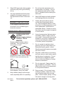
13 HP, 30 GalLON Air
compressor
65204
99918
Set up and Operating Instructions
Using an engine indoors CAN KILL YOU IN
MINUTES.
Engine exhaust contains carbon monoxide.
This is a poison you cannot see or smell.
NEVER use inside
a home or garage,
EVEN IF doors and
windows are open.
Only use OUTSIDE
and far away from
windows, doors,
and vents.
Visit our website at: http://www.harborfreight.com
Read this material before using this product.
Failure to do so can result in serious injury.
Save this manual.
Copyright© 2008 by Harbor Freight Tools®. All rights reserved. No portion of this manual or any artwork
contained herein may be reproduced in any shape or form without the express written consent of
Harbor Freight Tools. Diagrams within this manual may not be drawn proportionally. Due to continuing
improvements, actual product may differ slightly from the product described herein. Tools required for
assembly and service may not be included.
For technical questions or replacement parts, please call 1-800-444-3353.
Manual revised 09c, 09e, 09i
Contents
Important SAFETY
Information���������������������������� 3
Basic Specifications������������� 8
Components and Controls8
Equipment Set Up�������������������� 9
Unpacking��������������������������������������� 9
Mounting�����������������������������������������9
Equipment Oil Fill����������������������� 9
Operating Instructions���� 10
Work Piece and Work Area
Set Up������������������������������������������10
General Operating
Instructions���������������������������� 10
User-Maintenance
Instructions������������������������ 12
Cleaning, Maintenance, and
Lubrication������������������������������� 12
Daily������������������������������������������12
Weekly��������������������������������������12
Monthly����������������������������������� 12
Troubleshooting���������������������� 14
PARTS Lists������������������������������ 16
Main ASSEMBLY DIAGRAM������ 17
Pump ASSEMBLY DIAGRAM����� 18
Limited 1 year / 90 day
Warranty������������������������������ 19
SKU 65204/
99918
For technical questions, please call 1-800-444-3353.
Page 2
Save This Manual
NOTICE is used to
address practices
not related to personal injury.
Keep this manual for the safety warnings and precautions, assembly, operating, inspection, maintenance and cleaning
procedures. Write the product’s serial
number in the back of the manual near the
assembly diagram (or month and year of
purchase if product has no number). Keep
this manual and the receipt in a safe and
dry place for future reference.
CAUTION, without
the safety alert
symbol, is used to address
practices not related to
personal injury.
WARNING! Read all instructions.
Failure to follow all instructions
listed below may result in fire,
serious injury and/or DEATH.
The warnings and precautions
discussed in this manual cannot
cover all possible conditions and
situations that may occur. It must
be understood by the operator that
common sense and caution are
factors which cannot be built into
this product, but must be supplied
by the operator.
Important SAFETY
Information
In this manual, on the labeling,
and all other information
provided with this product:
This is the safety alert
symbol. It is used to alert
you to potential personal
injury hazards. Obey all
safety messages that
follow this symbol to avoid
possible injury or death.
DANGER indicates
a hazardous
situation which, if not
avoided, will result in death or
serious injury.
WARNING
indicates a
hazardous situation which, if
not avoided, could result in
death or serious injury.
CAUTION, used
with the safety
alert symbol, indicates a
hazardous situation which, if
not avoided, could result in
minor or moderate injury.
SKU 65204/
99918
SAVE THESE INSTRUCTIONS
Set up precautions
1.
Gasoline fuel and fumes are flammable, and potentially explosive. Use
proper fuel storage and handling procedures. Do not store fuel or other
flammable materials nearby.
2.
Have multiple ABC class fire extinguishers nearby.
3.
Operation of this equipment may create sparks that can start fires around
dry vegetation.
A spark arrestor may be required.
The operator should contact local fire
agencies for laws or regulations relating to fire prevention requirements.
4.
Set up and use only on a flat, level,
well-ventilated surface.
For technical questions, please call 1-800-444-3353.
Page 3
5.
Wear ANSI-approved safety goggles
and heavy-duty work gloves during
set up.
6.
Use only lubricants and fuel recommended in the engine manual or in
the Specifications chart of this manual.
Engine precautions
3.
Do not leave the equipment unattended when it is running. Turn off
the equipment (and remove safety
keys, if available) before leaving the
work area.
4.
Wear ANSI-approved safety glasses
and hearing protection during use.
5.
People with pacemakers should
consult their physician(s) before
use. Electromagnetic fields in close
proximity to a heart pacemaker could
cause pacemaker interference or
pacemaker failure. Caution is necessary when near the engine’s magneto
or recoil starter.
6.
Use only accessories that are recommended by Harbor Freight Tools for
your model. Accessories that may be
suitable for one piece of equipment
may become hazardous when used
on another piece of equipment.
7.
Do not operate in explosive atmospheres, such as in the presence of
flammable liquids, gases, or dust.
Gasoline-powered engines may ignite
the dust or fumes.
8.
Stay alert, watch what you are doing
and use common sense when operating this piece of equipment. Do not
use this piece of equipment while
tired or under the influence of drugs,
alcohol or medication.
9.
Do not overreach. Keep proper footing and balance at all times. This enables better control of the equipment
in unexpected situations.
Follow engine precautions and instructions in the included engine
instruction manual.
Operating precautions
1.
Carbon Monoxide
Hazard
Using an engine indoors
CAN KILL YOU IN
MINUTES.
Engine exhaust contains carbon
monoxide. This is a poison you
cannot see or smell.
NEVER use inside a home or garage,
EVEN IF doors and windows are
open.
Only use OUTSIDE and far away
from windows, doors, and vents.
2.
Keep children away from the equipment, especially while it is operating.
SKU 65204/
99918
10. Dress properly. Do not wear loose
clothing or jewelry. Keep hair, clothing and gloves away from moving
parts. Loose clothes, jewelry or long
hair can be caught in moving parts.
For technical questions, please call 1-800-444-3353.
Page 4
serviced before using. Many accidents are caused by poorly maintained equipment.
11. Parts, especially exhaust system
components, get very hot during use.
Stay clear of hot parts.
12. Do not cover the engine or equipment
during operation.
13. Keep the equipment, engine, and surrounding area clean at all times.
14. Use the equipment, accessories, etc.,
in accordance with these instructions
and in the manner intended for the
particular type of equipment, taking
into account the working conditions
and the work to be performed. Use
of the equipment for operations different from those intended could result
in a hazardous situation.
15. Do not operate the equipment with
known leaks in the engine’s fuel system.
20. Use the correct equipment for the
application. Do not modify the equipment and do not use the equipment
for a purpose for which it is not intended.
Service precautions
1.
Before service, maintenance, or
cleaning:
a.Turn the engine switch to its
“OFF” position.
b.Allow the engine to completely
cool.
c. Then, remove the spark plug
wire(s) from the spark plug(s).
2.
Keep all safety guards in place and in
proper working order. Safety guards
include the belt guard, muffler, air
cleaner, mechanical guards, and heat
shields, among other guards.
3.
17. When spills of fuel or oil occur, they
must be cleaned up immediately.
Dispose of fluids and cleaning materials as per any local, state, or federal
codes and regulations. Store oil rags
in a bottom-ventilated, covered, metal
container.
Do not alter or adjust any part of
the equipment or its engine that is
sealed by the manufacturer or distributor. Only a qualified service
technician may adjust parts that
may increase or decrease governed engine speed.
4.
18. Keep hands and feet away from
moving parts. Do not reach over or
across equipment while operating.
Wear ANSI-approved safety goggles,
heavy-duty work gloves, and dust
mask/respirator during service.
5.
Maintain labels and nameplates on
the equipment. These carry important information. If unreadable or
missing, contact Harbor Freight Tools
for a replacement.
16. This product contains or, when used,
produces a chemical known to the
State of California to cause cancer
and birth defects or other reproductive harm. (California Health & Safety
Code § 25249.5, et seq.)
19. Before use, check for misalignment
or binding of moving parts, breakage
of parts, and any other condition that
may affect the equipment’s operation.
If damaged, have the equipment
SKU 65204/
99918
For technical questions, please call 1-800-444-3353.
Page 5
6.
Have the equipment serviced by a
qualified repair person using only
identical replacement parts. This will
ensure that the safety of the equipment is maintained. Do not attempt
any service or maintenance procedures not explained in this manual
or any procedures that you are uncertain about your ability to perform
safely or correctly.
7.
Store equipment out of the reach of
children.
8.
Follow scheduled engine and equipment maintenance.
9.
Tanks rust from moisture build-up,
weakening the tank. Drain tank daily
and inspect periodically.
10. Do not remove or adjust safety valve.
11. Refueling:
a.Do not smoke, or allow sparks,
flames, or other sources of ignition
around the equipment, especially
when refuelling.
b.Do not refill the fuel tank while the
engine is running or hot.
c. Do not fill fuel tank to the top. Leave
a little room for the fuel to expand as
needed.
d.Refuel in a well-ventilated area only.
Save these
instructions.
SKU 65204/
99918
For technical questions, please call 1-800-444-3353.
Page 6
This page intentionally
left blank
SKU 65204/
99918
For technical questions, please call 1-800-444-3353.
Page 7
ing parts and allows the large pulley
to direct cooling air to the Air Pump
(A2).
Basic Specifications
Equipment Type
Lubricant
Capacity
1.37 Quarts
13 HP, EPA/CARB
Compliant
13 HP, EPA Compliant
65204
Engine
Compressor Oil
99918
Rotation viewed from PTO Counterclockwise
(power takeoff - the output shaft)
Engine Shaft
Ø 1” x 2-7/8” Long
1/ ” Keyway
4
3/ ”-24 UNF inner thread
8
Air Pressure Range
145-175 PSI
Air Outlet
3/4" NPT
2.
Oil Sight Glass. The oil sight glass
shows proper level of the oil. Oil level
should be at center of Sight Glass.
3.
Tank Drain Valve. The Air Tank (A18)
drain valve allows moisture to be
removed from the tank to reduce the
chance of corrosion inside the tank.
4.
Safety Valve. This Safety Valve (A15)
automatically releases air if the Air
Tank (A18) pressure exceeds the
preset maximum.
19.5 CFM @ 40 PSI
18.7 CFM @ 100 PSI
1,800±100 RPM
Air Flow
Engine Idle Speed
a.In an emergency, the ring could be
pulled to reduce tank air pressure.
(Pressure switch controlled)
Note: Engine specifications are found in
the engine manual supplied with this
equipment.
5.
Components and
Controls
Belt Guard
Pilot
Valve
Safety
Valve
Ball
Valve
Tank Drain
Regulator and Gauge (Not Included).
Outlet air can be regulated by adjusting the regulator knob. Clockwise will
raise outlet pressure and counterclockwise will lower outlet pressure.
Outlet pressure will be displayed on
the regulator’s pressure gauge.
Air
Filter
Oil
Sight
Glass
Tank Pressure
Gauge
Ball Valve. Air hose attaches to this
valve. Air pressure required by tools
is set by an air pressure regulator.
6.
Air Storage Tank. The Air Tank (A18)
is where air pressurized by the Air
Pump (A2) is stored for later use.
7.
Tank Pressure Gauge. The Air Tank
Pressure Gauge (A20) displays the
air pressure in the tank.
Air Storage Tank
Fig. 1
1.
Belt Guard. The Belt Guard (A1)
encloses the pulleys and drive belts.
It protects the user from the mov-
SKU 65204/
99918
For technical questions, please call 1-800-444-3353.
Page 8
Mounting
Pilot
Valve
8.
Pilot Valve. Open the Pilot Valve
before starting the engine. It relieves
resistance on the engine to make
starting easier. It is shown in the
open position above. Push the pin
over to one side to close it.
Equipment Set Up
Read the entire Important
Safety Information
section at the beginning of this
manual including all text under
subheadings therein before set
up or use of this product.
Note: For additional information regarding
the parts listed in the following pages,
refer to the Assembly Diagrams near
the end of this manual.
Unpacking
Note: Do not use the air cleaner to lift or
move the compressor. It is not designed to withstand such force.
1.
The compressor may vibrate strongly
during use, so mounting is needed to
prevent movement.
2.
Before use, mount the compressor
securely using all four mounting holes
to a solid, level surface, such as a
concrete slab or truck bed.
3.
Rubber pads (not included) may be
used at the mounting points to reduce
vibration.
Equipment Oil Fill
IMPORTANT. To prevent property
damage and voiding of the
warranty:
Before first use, fill the compressor with compressor oil as follows:
1.
Remove the Breather Vent (22) and
fill with 1.37 quarts of premium quality
SAE 30-weight, non-detergent, synthetic air compressor oil. Do not mix
oils of different types.
2.
Check the oil level at the Oil Sight
Glass. The oil level should be at the
middle of the Glass. Add or drain
oil as needed until it is at the proper
level.
3.
Thread the Breather Vent (22) back
into place, being careful not to crossthread it or strip its threads.
When unpacking, make sure that the
item is intact and undamaged. If any parts
are missing or broken, please call Harbor
Freight Tools at 1-800-444-3353 as soon
as possible.
REV 09c
SKU 65204/
99918
For technical questions, please call 1-800-444-3353.
Page 9
Operating Instructions
General
Operating Instructions
Read the entire Important
Safety Information
section at the beginning of this
manual including all text under
subheadings therein before set
up or use of this product.
Before starting the engine:
a.Follow the Set Up
Instructions to prepare the
equipment.
b.Inspect the equipment and
engine.
c. Fill the engine with the
proper amount and type of
both fuel and oil. Note: The
Oil Sensor (if equipped)
will prevent the engine
from operating if the oil is
not up to the proper level.
NOTE: THIS ENGINE
INCLUDES AN AUTOMATIC
LOW OIL SHUTDOWN
SENSOR THAT DISABLES
THE ENGINE IF THE OIL
LEVEL IS TOO LOW.
d.For electric start, make
sure battery is 12 V, 36+
Ah, is fully charged, and is
correctly connected with
proper cables.
Inspect compressor before
use, looking for damaged,
loose, and missing parts. If any
problems are found, do not use
until repaired.
Work Piece and Work Area Set Up
1.
The Compressor’s engine runs on
gasoline and must be set up in an
area free from ignition sources.
2.
Do not set up too close to a wall or
in a confined area. The Air Pump
(A2) and Gas Engine (A4) must have
adequate fresh air in order to operate
properly and not overheat.
3.
Designate a work area that is clean
and well-lit. The work area must not
allow access by children or pets to
prevent injury and distraction.
1.
Route the air hose along a safe route
to reach the work area without creating a tripping hazard or exposing the
air hose to possible damage. The air
hose must be long enough to reach
the work area with enough extra
length to allow free movement while
working.
Set up air system according to air
tool’s instructions (sold separately).
All lubricated compressor pumps discharge some condensed water and
oil with the compressed air. Components such as air dryers, moisture filters, regulators, and automatic oilers
may be required.
2.
Open the Fuel Valve.
3.
Close the Choke.
4.
Check the compressor oil level (using
the Oil Sight Glass) and the engine
oil level. Add oil as needed.
5.
Empty all air pressure from the tank.
4.
REV 09c, 09i
SKU 65204/
99918
For technical questions, please call 1-800-444-3353.
Page 10
6.
Before starting the engine, open the
Pilot Valve by standing the pin up.
Starter Control Panel
Start
Ignition Switch
Ignition
Switch
S
S
0
Off
Charging System
Circuit Protector
(Close-up)
7a. To start the engine using the electric
starter:
Insert the ignition key into the ignition. While turning the key to Start (S
position, max 5 seconds) very slowly
move the choke lever from cold to run
position.
Note: To prolong starter life, use
short starting cycles (5 seconds maximum). Then wait one minute before
attempting to start again.
5b. To start the engine manually:
To re-start a warm engine, move the
Choke to halfway closed. Insert the
ignition key into the Ignition and turn
the Key to Run (I position). Grasp
the starter handle, and pull slowly
until resistance is felt. While holding
the handle, allow the starter rope to
rewind slowly. Then, pull the starter
handle with a rapid, full arm stroke.
Once again while holding the handle,
allow the rope to rewind slowly. Repeat as necessary, until the engine
starts.
6.
7.
IMPORTANT: Allow the engine to run
at no load for five minutes after each
start-up so that the engine can stabilize.
8.
Close the pilot valve after the engine
has started, by laying the pin down.
This allows the compressor to build
up pressure.
9.
When the Gas Engine (A4) is started
and running, the Air Pump (A2) starts
compressing air into the Air Tank
(A18) for storage.
Charging System
Overload Indicator
0
Run
Note: Moving the Choke too fast could kill
the engine.
10. When maximum tank pressure is
reached, the compressor automatically disengages, and the engine
RPM drops down to idle speed. The
engine remains at idle until Air Tank
pressure falls to a preset level. The
Gas Engine will then accelerate and
air pressure once again begins to
build up in the Air Tank.
11. To turn off the engine, turn the key off
(0 position). Close the fuel valve.
12. Drain the moisture from the tank
daily.
Allow the Engine to run for several seconds. Then, if the Choke is
closed, open it (move to the run position).
SKU 65204/
99918
For technical questions, please call 1-800-444-3353.
Page 11
User-Maintenance
Instructions
Procedures not specifically
explained in this manual
must be performed only by a
qualified technician.
To prevent
serious injury
from accidental
operation:
Disconnect spark plug and
release all air pressure before
maintenance.
To prevent serious
injury from tool
failure:
Do not use damaged
equipment. If abnormal noise,
vibration, or leaking air
occurs, have the problem
corrected before further use.
To prevent serious
injury:
Do not adjust or tamper with
any control or component in a
way not specifically explained
within this manual. Improper
adjustment can result in tool
failure or other serious
hazards.
Cleaning, Maintenance, and
Lubrication
Note: These procedures are in addition to
the regular checks and maintenance
explained as part of the regular operation of the air-operated tool.
SKU 65204/
99918
Daily
1.
Check compressor oil level at sight
glass. Add premium quality SAE
30-weight, non-detergent, synthetic
air compressor oil as needed. Do not
mix oils of different types.
2.
Check engine oil level. Add oil as
needed according to engine manual’s
instructions.
3.
Drain moisture from tank.
Weekly
1.
Inspect air pump’s Air Filter (67). Replace if necessary. To replace:
a.Unscrew the wing nut holding the
filter cover.
b.Remove the filter cover.
c. Remove the filter element and replace with a new one.
d.Slide the filter cover back over the
filter element and screw the wing nut
back on and tighten securely.
2.
Check safety valve by pulling and releasing ring. Valve should seal once
released.
3.
Clean excessive dirt/dust from unit.
Monthly
Check and adjust belt tension according to the steps below:
1.
Remove the belt cover and set it
aside.
For technical questions, please call 1-800-444-3353.
Page 12
Deflection
Distance
2.
Press on the center of the longest
span on each belt with moderate
finger pressure (4-4.5 lb.). Then
measure the deflection distance, the
distance that the belt moved. The
belt should deflect anywhere from
1/4” to 1/2”.
Engine Mounting Bolts
3.
If the belts deflect too much,
tighten belts by loosening the engine mounting bolts and moving the
engine away from the other pulley
slightly. Secure engine mounting
bolts and retest tension. If either belt
is too long to be properly tensioned,
both belts must be replaced.
4.
If the belts deflect too little, loosen
belts by loosening the engine mounting bolts and moving the engine
towards the other pulley very slightly.
Secure engine mounting bolts and
retest tension.
5.
Align pump and engine pulleys using
a straight edge to reduce noise and
vibration.
6.
Before use, replace belt cover.
SKU 65204/
99918
For technical questions, please call 1-800-444-3353.
Page 13
Troubleshooting
Problem
Engine will not
start.
Possible Causes
Start procedure not followed
completely.
1. Incorrect lubrication or not
enough lubrication.
Compressor overheats.
2. Worn parts.
1. Poor air outlet seal.
2. Loose cylinder/cylinder head.
Severe air
leakage.
3. Damaged valve or housing.
4. Dirty, worn or damaged valve.
1. Low engine idle.
Unit stalls
2. Severely clogged air filter.
3. Improper lubrication.
4. Defective pilot/unloader valve.
1. Loose drive pulley or flywheel.
2. Misaligned pulleys.
Excessive noise
3. Lack of oil in crankcase.
4. Worn connecting rod.
5. Worn wrist pin bushing.
6. Worn bearings.
7. Loose belts.
1. Wrong type of oil or low-quality
oil.
Oil in the discharge 2. Overheating.
air
3. Restricted intake air.
4. Worn piston rings.
5. Excessive moisture in the tank.
Likely Solutions
Empty all pressure from tank, open pilot valve,
and carefully follow starting instructions in
engine manual.
1. Lubricate using recommended oil or grease
according to directions.
2. Have qualified technician inspect internal
mechanism and replace parts as needed.
1. Tighten or re-attach using thread seal tape.
2. Tighten cylinder/cylinder head assembly. If
cylinder/cylinder head cannot tighten properly,
internal parts may be misaligned.
3. Replace damaged components.
4. Clean or replace valve assembly.
1. Qualified technician should increase idle to
1,800±100 RPM by adjusting pressure switch.
2. Replace air filter.
3. Check for proper oil level.
4. Replace.
1. Loose pulleys are a common cause of
“knocking”. Tighten appropriate bolts.
2. Align pulleys with straightedge and secure in
place.
3. Check for proper oil level.
4. Replace.
5. Remove piston assembly and replace
necessary parts.
6. Replace bearings and oil.
7. Check for proper belt tension.
1. Change oil. Check oil recommendations
under Equipment Set Up, Equipment Oil
Fill section of this manual.
2. See above section.
3. Clean or replace air filter.
4. Replace.
5. Drain moisture from the tank daily.
Follow all safety precautions whenever diagnosing or
servicing the tool.
SKU 65204/
99918
For technical questions, please call 1-800-444-3353.
Page 14
Troubleshooting
Problem
Possible Causes
1. Air leaks.
2. Leaking valves.
Low discharge
pressure
3. Restricted air intake.
4. Blown gaskets.
5. Slipping belts.
Likely Solutions
1. Listen for escaping air. Apply soap solution
to all fittings and connections. Bubbles will
appear at points of leakage. Tighten or
replace leaking fittings or connections.
2. Remove head and inspect for valve
breakage, weak valves, scored valve plate,
etc. Replace defective parts and reassemble.
Replace head gasket each time the head is
removed.
3. Clean or replace air filter element.
4. Replace and gaskets proven faulty on
inspection.
5. Tighten Belts (See monthly maintenance.)
Follow all safety precautions whenever diagnosing or
servicing the tool.
PLEASE READ THE FOLLOWING CAREFULLY
The manufacturer and/or distributor has provided the parts list and assembly
diagram in this manual as a reference tool only. Neither the manufacturer or
distributor makes any representation or warranty of any kind to the buyer that
he or she is qualified to make any repairs to the product, or that he or she is
qualified to replace any parts of the product. In fact, the manufacturer and/
or distributor expressly states that all repairs and parts replacements should
be undertaken by certified and licensed technicians, and not by the buyer. The
buyer assumes all risk and liability arising out of his or her repairs to the
original product or replacement parts thereto, or arising out of his or her
installation of replacement parts thereto.
SKU 65204/
99918
For technical questions, please call 1-800-444-3353.
Page 15
PARTS Lists
Part
A1
A2
A4
A5
A6
A7
A8
A9
A10
A11
A13
A14
A15
A16
A17
A18
A19
A20
A21
A22
A23
A24
Part
1
2
3
4
5
6
7
8
9
10
11
12
13
14
15
16
17
18
19
20
21
22
Description
Belt Guard
Air Pump
Gasoline Engine
Engine Mounting Bolt
Lock Washer
Flat Washer
Nut
Belt
Belt Pulley (Engine)
Key
Pilot/Unloader Valve with Cable
Elbow
Safety Valve
Air Outlet Valve
Drain Valve
Air Tank
“T” Connector
Pressure Gauge
Air Hose
Air Hose Connector
Belt Cover Mount Plate
Spark Plug Wrench
Description-Pump
Key
Screw
Nut
Flywheel
Oil Seal Circle
Hex Head Bolt
Rear-front Plate
Bearing Sleeve
Bearing
Crankshaft
Gasket
Crankcase
Crankcase Bottom Gasket
Crankcase Bottom
Oil Fill Plug
Oil Drain Tube
Gasket
Oil Sight
Screw
Gasket
Rear-end Plate
Breather Vent
SKU 65204/
99918
Qty
1
1
1
12
12
12
12
2
1
1
1 set
1
1
1
1
1
2
1
1
2
4
1
Qty
1
1
1
1
1
16
1
2
2
1
1
1
1
1
3
1
1
1
2
1
1
1
23
24
25
26
27
28
29
30
31
32
33
34
35
36
37
38
39
40
41
42
43
44
45
46
47
48
49
50
51
52
53
54
55
56
57
58
59
60
61
62
63
64
65
66
67
68
69
70
71
Gasket
Cylinder
Spring Washer
Bolt
Gasket
Cylinder Head
Gasket
Aftercooler
Connector
Elbow 90 Degree
Safety Valve
Spring Washer
Screw
Spring Washer
Screw
Gasket
Elbow
Screw
Spring Washer
Intercooler
Safety Valve
Screw
Spring Washer
Shaft Jaw (2 Per Rod)
Connecting Rod
Internal Retainer Ring
Piston Pin
LP Piston
Piston Ring
HP Piston
Piston Pin
Piston Ring
Washer
Intake Valve Plate
Intake Valve Plate
Exhaust Valve Plate
LP Locating Ring
HP Locating Ring
2 Hole Stopper Ring
3 Hole Stopper Ring
Gasket
Bonnet
Spring Washer
Screw
Air Pump Filter
Flywheel
Gasket
Spring Washer
Bolt
For technical questions, please call 1-800-444-3353.
1
1
6
6
1
1
2
1
1
2
1
4
4
8
8
1
1
2
2
1
1
4
4
2 set
2 set
4
1
1
1 set
1
1
1 set
5
2 set
1 set
2 set
3
2
2
3
3
3
3
3
1
1
1
2
2
Page 16
Main ASSEMBLY DIAGRAM
Parts List “A”
Spark Plug Wrench (A24)
SKU 65204/
99918
For technical questions, please call 1-800-444-3353.
Page 17
Pump ASSEMBLY DIAGRAM
Record Product’s Serial Number Here:
Note: If product has no serial number, record month and year of purchase instead.
Note: Some parts are listed and shown for illustration purposes only, and are not available individually as replacement parts.
SKU 65204/
99918
For technical questions, please call 1-800-444-3353.
Page 18
Limited 1 year / 90 day Warranty
Harbor Freight Tools Co. makes every effort to assure that its products meet high
quality and durability standards, and warrants to the original purchaser that for a period
of one year from date of purchase that the tank is free of defects in materials and workmanship (90 days if used by a professional contractor or if used as rental equipment).
Harbor Freight Tools also warrants to the original purchaser, for a period of ninety days
from date of purchase, that all other parts and components of the product are free from
defects in materials and workmanship. This warranty does not apply to damage due directly or indirectly to misuse, abuse, negligence or accidents, repairs or alterations outside our facilities, normal wear and tear, or to lack of maintenance. We shall in no event
be liable for death, injuries to persons or property, or for incidental, contingent, special
or consequential damages arising from the use of our product. Some states do not allow
the exclusion or limitation of incidental or consequential damages, so the above limitation of exclusion may not apply to you. This warranty is expressly in lieu of
all other warranties, express or implied, including the warranties
of merchantability and fitness.
To take advantage of this warranty, the product or part must be returned to us with
transportation charges prepaid. Proof of purchase date and an explanation of the complaint must accompany the merchandise. If our inspection verifies the defect, we will either repair or replace the product at our election or we may elect to refund the purchase
price if we cannot readily and quickly provide you with a replacement. We will return repaired products at our expense, but if we determine there is no defect, or that the defect
resulted from causes not within the scope of our warranty, then you must bear the cost
of returning the product.
This warranty gives you specific legal rights and you may also have other rights
which vary from state to state.
3491 Mission Oaks Blvd. • PO Box 6009 • Camarillo, CA 93011 • (800) 444-3353
SKU 65204/
99918
For technical questions, please call 1-800-444-3353.
Page 19