1
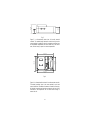
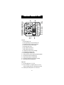
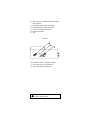
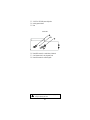
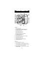
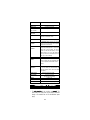
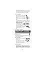
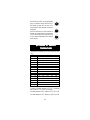
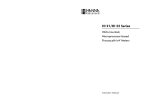
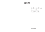
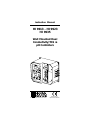
Instruction Manual
HI 9913 - HI 9923
HI 9935
Wall Mounted Dual
Conductivity/TDS &
pH Controllers
FE
5
SLOP
E
0
ALAR
M
ON
1.5
ALAR 2
M
1
ALA
ACID
OFFS
ET
0.5
1
0
pH
ACID
OFF
mS
ALK
2.5
2.0
pH
0
PROP
ORTIO
SE
NAL
SETT CONDS 90
INGS
SET
5
ALAR
M
7.5
1
EC
MINU
10
TE
TIMER S
mS
mS
FERT
ZERO
CAL
SLOP
E CA
L
0.5
1.5
2
4
0
0
pH
HI 99
1
pH
SET
pH
SET
EC
ALA
FEE
2
3
ON
ALAR
M
OFF
2.0
mS
0
PROP
ORTIO
NAL
SE
SETT COND 90
INGS S
2.5
1
5
SET
7.5
1
MINU
10
TES
TIMER
LINE
http://www.hannainst.com
These Instruments are in
Compliance with the CE Directives
Dear Customer,
Thank you for choosing a Hanna Product.
Please read this instruction manual carefully before using the instrument. This manual will provide you with the necessary information for
a correct use of the instrument, as well as a more precise idea of its
versatility. If you need more technical information, do not hesitate to
e-mail us at [email protected].
These instruments are in compliance with the
directives
EN 50081-1, 50082-1 and 61010-1.
TABLE OF CONTENTS
PRELIMINARY EXAMINATION ........................................................ 3
GENERAL DESCRIPTION ................................................................ 3
MECHANICAL LAYOUTS................................................................. 4
FUNCTIONAL DIAGRAM HI 9913 .................................................. 6
FUNCTIONAL DIAGRAM HI 9923 .................................................. 9
FUNCTIONAL DIAGRAM HI 9935 ................................................ 12
CONNECTIONS & WIRING .......................................................... 14
NORMAL OPERATION & MEASUREMENT ..................................... 19
pH CALIBRATION ....................................................................... 20
CONDUCTIVITY/TDS CALIBRATION................................................ 21
ADJUSTMENT OF SETPOINT(S) ................................................... 23
PROPORTIONAL CONTROL .......................................................... 24
CONDUCTIVITY DEAD BAND (HI 9923) ........................................ 26
OVERDOSAGE TIMERS ................................................................ 26
pH VALUES AT VARIOUS TEMPERATURES ................................... 27
pH ELECTRODE CONDITIONING & MAINTENANCE ......................... 28
CONDUCTIVITY/TDS PROBE CLEANING & MAINTENANCE ............... 29
SUGGESTED INSTALLATIONS FOR pH ELECTRODE ........................ 30
SUGGESTED INSTALLATIONS FOR EC/TDS PROBE ........................ 31
ACCESSORIES ............................................................................. 33
WARRANTY ................................................................................ 34
CE DECLARATION OF CONFORMITY .............................................. 35
ISO 9000 Certified
Company since 1992
2
PRELIMINARY EXAMINATION
Remove the instrument from the packing material and examine it
carefully to make sure that no damage has occurred during shipping. If there is any noticeable damage, notify your Dealer.
Note: Save all packing materials until you are sure that the
instrument functions correctly. Any defective item must be
returned in the original packaging together with the supplied
accessories.
IMPORTANT:
1. Read the instructions before using the instrument.
2. The instrument should be connected to a mains socket.
3. Never install the controller outdoors, in a wet or humid area or
under direct sun light. Nor install the controller where liquids
may be sprayed or poured on it.
4. The instrument’s main power line as well as the dosage and
alarm terminals are protected by separate 2A fuses. Use only 2A
fuses for replacement.
GENERAL DESCRIPTION
Hanna's wall-mounted conductivity/TDS and pH controllers are
designed to meet a variety of process control requirements, especially
those in horticultural, hydroponics and agricultural applications on
the one hand and boilers and cooling towers on the other.
All controllers provide for two separate relays, one for pH and another
for Conductivity/TDS. HI 9913 and HI 9935 also come with proportional control to save on use of chemicals and fertilizers.
All models operate with the optional Hanna 4-ring probes to provide
a linear and repeatable measurement. The conductivity/TDS probes
can be installed quickly and easily. Simply plug the DIN connector
into the socket and tighten the retainer ring.
The EC/TDS probes incorporate a temperature sensor and the controllers will automatically compensate for the temperature effect. Accurate
measurements are displayed on a large LCD.
Similarly, the pH electrode can be installed quickly and easily. Simply
plug the universal BNC connector into the socket and twist it into a
secured position. In order to avoid electrical noise and interference,
the pH circuitry also provides for a ground probe (differential input).
3
The controllers come equipped with relays operating at a maximum of
2A (240V).
They incorporate a triple contact alarm system. When activated, the
alarm contacts will open or close, triggering the mechanism of your
choice, whether a buzzer, light or any other electrical device.
The controllers are housed in a rugged, modular, fiber-reinforced ABS
housing.
All models can be wired to work with 110/115V or 220/240V at
50/60 Hz power supplies.
MECHANICAL LAYOUTS
BNC CONNECTOR
MATCHING PIN FOR GROUND PROBE
DIN CONNECTOR
WIRING ACCESS
PORTS
Fig. 1
Figure 1 illustrates the connector for pH electrode, matching pin
connection, conductivity/TDS probe and the wiring access ports.
MATCHING PIN
LCD DISPLAY
HI 9913
CALIBRATION
TRIMMERS
CONTROL KNOBS
AND SWICHES
pH
1
pH
pH
ALARM
ACID
FEED
0
SLOPE
ALARM
4
ON
7
0
SET
ALARM CONTACTS
2
mS
5
ALK
2.5
1.5
2
ACID
OFF
0.5
ALARM
1
6
5
OFFSET
7.5
ALARM
0
2.0
0
pH
SECONDS
PROPORTIONAL SETTINGS
90
10
1
MINUTES
TIMER
DOSING TERMINALS
SET pH
mS
EC
SLOPE CAL
ALARM
1
SET
90
POWER SUPPLY
TERMINALS
4
5
2.5
1.5
2.0
0
mS
SECONDS
PROPORTIONAL SETTINGS
SET EC
3
ON
OFF
0
FEED
2
ZERO CAL
0.5
ALARM
FERT
mS
7.5
10
1
MINUTES
TIMER
LINE
Fig. 2
Figure 2 illustrates the controls and terminals.
4
3“
75 mm
25 mm
1“
96.9 mm
3.8“
Fig. 3
Figure 3 is a dimensioned, bottom view of the wall mounted
controller. The modular design isolates the control circuitry from the
contacts making it possible to make the connections and then close
the compartment. Adjustments can then be made only in the control
area, without having to open the contacts compartment.
6.9“
174.8 mm
7.4“
188.6 mm
227.8 mm
9“
221.8 mm
8.7“
Fig. 4
Figure 4 is a dimensioned front view of the wall mounted controller.
The molded, mounting holes in the corners provide for quick and
secure installation. No additional hardware is needed for mounting.
All electrical connections and controls are located on the front of the
instrument so that adjustment can be made without having to
remove the unit.
5
FUNCTIONAL DIAGRAM HI 9913
FRONT PANEL
1
17
18
2
19
3
HI 9913
4
5
6
7
8
1
pH
10
11
12
13
pH
ALARM
ACID
FEED
0
SLOPE
ALARM
ACID
4
ON
7
SET
OFF
0.5
0
2
mS
5
ALK
2.5
1.5
2
ALARM
1
6
5
OFFSET
2.0
0
pH
SECONDS
PROPORTIONAL SETTINGS
90
20
7.5
ALARM
0
9
2
pH
10
1
MINUTES
TIMER
21
SET pH
mS
EC
SLOPE CAL
23
ON
ALARM
1
SET
2.5
1.5
2.0
0
90
mS
SECONDS
PROPORTIONAL SETTINGS
4
5
OFF
0
SET EC
3
2
ZERO CAL
22
FEED
FERT
mS
0.5
ALARM
7.5
10
1
MINUTES
TIMER
LINE
24
14
16
9
25
Left panel
1. Alarm LED signal for pH
2. Liquid Crystal Display for pH and Conductivity (EC)
3. Acid feed LED and dial to adjust the pH setpoint
4. Selection switch for Acid or Alkaline dosage
5. Alarm disable switch for pH
6. Slope calibration trimmer for pH
7. Offset calibration trimmer for pH
8. Proportional pH band and time cycle settings
9. Two independent overdosage timers
10. Alarm LED signal for Conductivity (EC)
11. Fertilizer feed LED and dial to adjust the Conductivity setpoint
12. Zero calibration trimmer for Conductivity (EC)
13. Slope calibration trimmer for Conductivity (EC)
14. Proportional Conductivity band and time cycle settings
16. Alarm disable switch for Conductivity (EC)
Right panel
17. pH alarm setting from 0.0 to 2.0 pH
18. Short the terminals if a pH ground probe is not in use, or
connect the ground probe wire to the Matching Pin terminal
19. Conductivity alarm setting from 0 to 2.0 mS/cm (EC)
6
20. Triple contact alarm in a Normally Closed (NC) or a Normally
Open (NO) position.
21. Powered dosage terminals (Relay) for pH correction
22. Powered dosage terminals (Relay) for EC correction
23. 110/115V or 220/240V power configuration
24. Incoming power terminals
25. Fuses
BOTTOM VIEW
26
27
28
26. Female BNC connector for a combination pH electrode
27. 4-mm Banana socket for the pH ground probe
28. Female DIN connector for Conductivity probe
Unplug the instrument from the power supply before
wiring or replacing the fuses.
7
Specifications
RANGE
HI 9913
0.00 to 14.00 pH and 0.00 to 10.00 mS/cm (EC)
RESOLUTION
ACCURACY
(@20°C/68°F)
0.01 pH and 0.01 mS/cm
±0.02 pH and ±2% F. S.
TYPICAL EMC
DEVIATION
±0.1 pH and ±2% F. S.
CALIBRATION
Through "OFFSET" and "SLOPE" trimmers for pH, and
“ZERO CAL” and “SLOPE CAL” for Conductivity (EC)
SETPOINT RANGE
From 4.0 to 7.0 pH and 1.0 to 4.0 mS/cm (EC)
PROPORTIONAL
CONTROL
Two independent controls: pH from 0.0 to 2.0 and
Conductivity (EC) from 0.0 to 2.0 mS/cm with two
separate time cycles from 0 to 90 seconds
ALARM
CONTACT
Terminals can be configured as normally open or
normally closed (isolated output Max. 2A, Max. 240V,
resistive load, 1,000,000 strokes). The alarm is
activated if pH falls below the setpoint by the userselectable interval (0.0 to 2.0 pH), or conductivity
exceeds the setpoint by more than the user-selectable
interval (0 to 2.0 mS/cm) or due to overdosage
Any combination pH electrode with a universal BNC
connector and Hanna Conductivity 4-ring
potentiometric probe with built-in temperature sensor
and DIN connector (optional)
Two sets of independent terminals (115 to 240V,
Max.2A, 1,000,000 strokes) are activated whenever
pH exceeds the pH setpoint and/or conductivity falls
below the EC setpoint
PROBE
DOSING
TERMINALS
POWER SUPPLY
ENVIRONMENT
WEIGHT
ENCLOSURE
CASE MATERIAL
220/240V or 110/115V at 50/60Hz
-10 to 50°C (14 to 122°F)
max. 95% RH non-condensing
1.6 Kg (3.5 lb.)
181 x 221 x 142mm (7.1 x 8.7 x 5.6")
Fiber-reinforced, self-extinguishing ABS
8
FUNCTIONAL DIAGRAM HI 9923
FRONT PANEL
1
17
18
2
19
3
5
6
pH
pH
7
0
FEED
SLOPE
AUTO
2
ALARM
1
7.5
OFFSET
20
1
ALARM
ALK
5
0
10
21
2
mS
SET
9
45
MANUAL
ALARM
10
22
90
1
MINUTES
pH TIMER
11
12
pH
HI 9923
mS
mS
SET pH
ALARM
BLEED
ZERO CAL
SLOPE CAL
SET EC
23
4
3
2
13
5
AUTO
6
1
SET
45
MANUAL
15
0.50
0
24
90
1
MINUTES
mS TIMER
mS
DEAD BAND
16
LINE
9
25
Left panel
1. Alarm LED signal for pH
2. Liquid Crystal Display for pH and Conductivity
3. Alkaline feed LED and dial to adjust the pH setpoint
5. Alarm disable switch for pH
6. Slope calibration trimmer for pH
7. Offset calibration trimmer for pH
9. Two independent overdosage timers
10. Alarm LED signal for Conductivity
11. Bleed LED and dial to adjust the Conductivity setpoint
12. Zero calibration trimmer for Conductivity
13. Slope calibration trimmer for Conductivity
15. Conductivity Dead Band setting
16. Alarm disable switch for Conductivity
Right panel
17. pH alarm setting from 0.0 to 2.0 pH
18. Short the terminals if a pH ground probe is not in use, or
connect the ground probe wire to the Matching Pin terminal
19. Conductivity alarm setting from 0 to 2.0 mS/cm
20. Triple contact alarm in a Normally Closed (NC) or a Normally
Open (NO) position.
21. Powered dosage terminals (Relay) for pH correction
22. Powered dosage terminals (Relay) for Conductivity correction
9
23. 110/115V or 220/240V power configuration
24. Incoming power terminals
25. Fuses
BOTTOM VIEW
26
27
28
26. Female BNC connector for a combination pH electrode
27. 4-mm Banana socket for the pH ground probe
28. Female DIN connector for conductivity probe
Unplug the instrument from the power supply before
wiring or replacing the fuses.
10
Specifications
RANGE
RESOLUTION
ACCURACY
(@20°C/68°F)
HI 9923
0.00 to 14.00 pH and 0.00 to 10.00 mS/cm (mmho/cm)
0.01 pH and 0.01 mS/cm (mmho/cm)
±0.02 pH and ±2% F. S.
TYPICAL EMC
DEVIATION
±0.1 pH and ±2% F. S.
CALIBRATION
Through "OFFSET" and "SLOPE" trimmers for pH, and
“ZERO CAL” and “SLOPE CAL” for Conductivity
SETPOINT RANGE
DEAD BAND
ALARM
CONTACT
PROBE
DOSING
TERMINALS
POWER SUPPLY
ENVIRONMENT
WEIGHT
ENCLOSURE
CASE MATERIAL
From 5.0 to 10.0 pH & 1.00 to 6.00 mS/cm (mmho/cm)
From 0.0 to 0.5 mS/cm (mmho/cm)
Terminals can be configured as normally open or
normally closed (isolated output Max. 2A, Max. 240V,
resistive load, 1,000,000 strokes). The alarm is activated
if pH exceeds the setpoint by the user-selectable interval
(0 to 2 pH), or Conductivity falls below the setpoint by
more than the user-selectable interval (0 to 2.0 mS/
cm) or due to overdosage
Any combination pH electrode with a universal BNC
connector and Hanna Conductivity 4-ring
potentiometric probe with built-in temperature sensor
and DIN connector (optional)
Two sets of independent terminals (115 to 240V, Max.
2A, 1,000,000 strokes) are activated whenever pH falls
below the pH setpoint or the conductivity exceeds the
“BLEED” setpoint
220/240V or 110/115V at 50/60Hz
-10 to 50°C (14 to 122°F)
max. 95% RH non-condensing
1.6 Kg (3.5 lb.)
181 x 221 x 142mm (7.1 x 8.7 x 5.6")
Fiber-reinforced, self-extinguishing ABS
11
FUNCTIONAL DIAGRAM HI 9935
FRONT PANEL
1
17
18
2
19
3
6
pH
9
2
10
11
12
13
SLOPE
2.0
0
pH
SECONDS
PROPORTIONAL SETTINGS
0
2
ALARM
200
6
4
7
400
ppm
SET
5
7.5
90
21
10
1
MINUTES
TIMER
SLOPE CAL
SET pH
ppm
ALARM
FERT
FEED
1200
1500
ALARM
900
SET
1800
5
OFF
2.5
400
0
90
ppm
SECONDS
PROPORTIONAL SETTINGS
22
23
ON
300
20
ALARM
SET EC
ZERO CAL
0
FEED
2.5
1.5
TDS
ppm
100
ACID
1
0
ALARM
0
ALARM
ON
OFF
0.5
pH
5
OFFSET
7
8
pH
HI 9935
5
7.5
10
1
MINUTES
TIMER
LINE
24
14
16
9
25
Left panel
1. Alarm LED signal for pH
2. Liquid Crystal Display for pH and TDS (ppm or mg/L)
3. Acid feed LED and dial to adjust the pH setpoint
5. Alarm disable switch for pH
6. Slope calibration trimmer for pH
7. Offset calibration trimmer for pH
8. Proportional pH band and time cycle settings
9. Two independent overdosage timers
10. Alarm LED signal for TDS
11. Fertilizer feed LED and dial to adjust the TDS setpoint
12. Zero calibration trimmer for TDS
13. Slope calibration trimmer for TDS
14. Proportional TDS band and time cycle settings
16. Alarm disable switch for TDS
Right panel
17. pH alarm setting from 0.0 to 2.0 pH
18. Short the terminals if a pH ground probe is not in use, or
connect the ground probe wire to the Matching Pin terminal
19. TDS alarm setting from 0 to 400 ppm (mg/L)
20. Triple contact alarm in a Normally Closed (NC) or a Normally
Open (NO) position.
12
21.
22.
23.
24.
25.
Powered dosage terminals (Relay) for pH correction
Powered dosage terminals (Relay) for TDS correction
110/115V or 220/240V power configuration
Incoming power terminals
Fuses
BOTTOM VEW
26
27
28
26. Female BNC connector for a combination pH electrode
27. 4-mm Banana socket for the pH ground probe
28. Female DIN connector for TDS probe
Unplug the instrument from the power supply before
wiring or replacing the fuses.
13
Specifications
HI 9935
0.00 to 14.00 pH and 0.00 to 1999 ppm (mg/L)
RANGE
RESOLUTION
ACCURACY
(@20°C/68°F)
0.01 pH and 1 ppm (mg/L)
±0.02 pH and ±2% F. S.
TYPICAL EMC
DEVIATION
±0.1 pH and ±2% F. S.
CALIBRATION
Through "OFFSET" and "SLOPE" trimmers for pH, and
“ZERO CAL” and “SLOPE CAL” for TDS
SETPOINT RANGE
From 4.0 to 7.0 pH and 900 to 1800 ppm (mg/L)
PROPORTIONAL
CONTROL
Two independent controls: pH from 0.0 to 2.0 and
TDS from 0.0 to 400 ppm (mg/L) with two separate
time cycles from 0 to 90 seconds
Terminals can be configured as normally open or
normally closed (isolated output Max. 2A, Max. 240V,
resistive load, 1,000,000 strokes). The alarm is
activated if pH falls below the setpoint by the userselectable interval (0 to 2 pH),or TDS exceeds the
setpoint by more than the user-selectable interval (0
to 400 ppm) or due to overdosage
0.65 ppm (mg/L) = 1 µS/cm
Any combination pH electrode with a universal BNC
connector and Hanna TDS 4-ring potentiometric probe
with built-in temperature sensor and DIN connector
(optional)
ALARM
CONTACT
TDS RATIO
PROBE
DOSING
TERMINALS
POWER SUPPLY
ENVIRONMENT
WEIGHT
ENCLOSURE
CASE MATERIAL
Two sets of independent terminals (115 to 240V, Max.
2A, 1,000,000 strokes) are activated whenever pH
exceeds the pH setpoint and for the TDS falls below
the TDS setpoint
220/240V or 110/115V at 50/60Hz
-10 to 50°C (14 to 122°F)
max. 95% RH non-condensing
1.6 Kg (3.5 lb.)
181 x 221 x 142mm (7.1 x 8.7 x 5.6")
Fiber-reinforced, self-extinguishing ABS
CONNECTIONS & WIRING
GENERAL POINTS
• The relay terminals of the controller are powered
powered. This
means that you can simply hook up your pump or electrovalve
directly to the controller and do not need additional power
supply.
14
• Unscrew the 4 screws on the right hand panel and remove the
cover and the gasket. Thread the wires through the access ports
on the right hand side of the controllers.
• Before connecting the controller to the mains, wire
the controller completely and make all the connections for
pumps, valves, alarm, probe, set the alarm threshold and adjust
the settings. Upon completion replace the cover
cover. Only then
connect the controller to the power supply.
pH ELECTRODE & GROUND PROBE CONNECTIONS
BNC CONNECTOR
MATCHING PIN FOR GROUND PROBE
DIN CONNECTOR
WIRING ACCESS
PORTS
• Simply attach any combination pH electrode with a male BNC
connector (such as HI 1002/3) to the female BNC socket located
on the bottom of the casing and twist it into a secure position.
• All controllers provide for a Ground Probe (differential input) to
reduce electrical noise and interference. The controller is shipped
with the Matching Pin and Reference terminals shorted (see 18 Functional Diagram). If you are not using a matching pin
(ground probe), leave the terminals shorted
and skip the next two paragraphs.
• It is recommended that only electrodes that
incorporate a matching pin (such as HI 1003/3) are utilized. In
this case simply attach the 4-mm banana connector of
the matching pin to the socket located next to the BNC
connector on the outer casing (see 27 and 18 - Functional
Diagram) and remove the jumpers shorting the matching
pin terminals.
• When using a separate probe for grounding purposes, wire it to
the Matching Pin terminals on the right hand panel and remove
the jumpers (see 18 - Functional Diagram).
NOTE:
NEVER leave the jumper in when
using an electrode with a matching
pin. This can shorten the life of the
electrode (reference) drastically.
15
REMOVE WHEN
USING MATCHING PIN
CONDUCTIVITY/TDS PROBE CONNECTION
• Attach the conductivity/TDS probe (HI 3002, HI 3001D or
HI 7638) to the DIN socket located on the bottom of the casing.
Align the guide on the connector with the socket, push the
connector in and tighten the retainer ring. (HI 3002 is more
suitable for direct immersion in the tank, vat or pipes. HI 3001D
can be mounted directly into a pipe and HI 7638 is recommended for high temperature and pressure applications).
• The probes incorporate a temperature sensor and the controller’s
circuitry automatically compensates for the temperature effect.
RELAY CONNECTIONS
• The controllers provide for two separate relays, one for pH and
another for Conductivity (or TDS).
• Wire the external devices (pumps or electrovalves) directly to the
relay terminal strips of the controller (see 21 and 22 - Functional
Diagram). The terminals are powered and hence you do
not need an external power supply for the pumps or
electrovalves.
• The relay for the pH is activated when pH exceeds the setpoint
(HI 9913 and HI 9935) or falls below the setpoint (HI 9923).
The relay for conductivity/TDS instead acts in the opposite direction, i.e. it is
activated when
the conductivity pH
(or TDS) falls below the setpoint EC
(HI 9913 and
HI 9935) or exceeds the setpoint
(HI 9923).
HI 9913
pH
1
pH
ALARM
ACID
FEED
0
OFFSET
SLOPE
ALARM
ACID
4
ON
7
SET
OFF
0.5
0
BL DOSING
PUMPS
2
mS
5
ALK
2.5
1.5
2
ALARM
1
6
5
7.5
ALARM
0
2.0
0
pH
SECONDS
PROPORTIONAL SETTINGS
90
10
1
MINUTES
TIMER
SET pH
mS
ALARM
FERT
mS
SLOPE CAL
ZERO CAL
1
ALARM
0
SET EC
3
ON
SET
2.5
1.5
2.0
0
90
mS
SECONDS
PROPORTIONAL SETTINGS
4
5
OFF
0.5
FEED
2
7.5
10
1
MINUTES
TIMER
LINE
ALARM CONNECTIONS
• The operator can select an alarm threshold of 0.0 to 2.0 pH by
turning the alarm knob (see 17 - Functional Diagram). If the pH
measurements fall below the setpoint (HI 9913 and HI 9935) or
are above the setpoint (HI 9923) by a margin greater than the
user-selectable alarm threshold, the alarm terminal is activated.
16
• The operator can similarly select an
pH
pH
1
1
alarm threshold of 0.0 to 2.0 mS/cm
(HI 9913 and HI 9923) or 0 to 400
0
ppm (HI 9935) by turning the alarm 0 ALARM 2 ALARM 2
200
1
knob (see 19 - Functional Diagram). If
the conductivity/TDS measurements ex400
0
2 0
ppm
ceed the setpoint (HI 9913 and HI
mS
9935) or the conductivity falls below
the setpoint (HI 9923) by a margin greater than the userselectable alarm threshold, the alarm terminal is activated.
• The alarm can be selected as normally closed ("NC") by connecting
the external device to the C and NC terminals or normally open
("NO") by connecting the external device to the C and NO
terminals.
• When activated, the alarm contacts will open or close, triggering
the mechanism of your choice. When the alarm is activated
all other terminals (such as dosing relay etc.) are
disactivated
disactivated. The alarm LED lights also come on.
HI 9913
pH
EXTERNAL ELECTRICAL
DEVICE ACTIVATED BY
AN ALARM CONDITION
1
pH
pH
ALARM
ACID
FEED
0
OFFSET
SLOPE
ALARM
ACID
4
ON
7
SET
OFF
0.5
0
2
mS
5
ALK
2.5
1.5
2
ALARM
1
6
5
7.5
ALARM
0
2.0
0
pH
SECONDS
PROPORTIONAL SETTINGS
90
10
1
MINUTES
TIMER
SET pH
mS
EC
SET EC
3
ON
ALARM
1.5
2.0
0
90
mS
SECONDS
PROPORTIONAL SETTINGS
1
SET
4
5
OFF
0
FEED
2
SLOPE CAL
ZERO CAL
0.5
ALARM
FERT
mS
2.5
7.5
10
1
MINUTES
TIMER
LINE
• The alarm AUTO/MANUAL switches are only to disable the
alarm terminal (e.g. the buzzer will not sound). However, all
other functions such as disactivation of the dosing relay remains
unvaried, i.e. the pump or electrovalve will cease to operate until
the alarm condition is alleviated.
• If the pH AUTO/MANUAL switch is in the MANUAL
AUTO
position, the buzzer/light will not come on if the
pH value is out. The alarm will be sounded for
Conductivity/TDS anomalies, unless likewise, the MANUAL
Conductivity/TDS switch is also in the manual
position.
• The controller provides for automatic fail-safe secruity by
activating the alarm if there is a power failure, regardless of
whether the NC or NO configurations were chosen.
17
• The alarm is also activated if one or both of the independent
maximum dosage times are exceeded. The
maximum time that the relay contacts remain
active continuously (max. dosage time) can be
set from 1 to 10 minutes for HI 9913 and
HI 9935 and 1 to 90 minutes for HI 9923.
• Once in an alarm condition, the contact remains activated until
the switch is put in the manual position or the measurements
return to normal values.
5
2.5
7.5
10
1
MINUTES
ALARM DOSING TIME
TEMPERATURE COMPENSATION
Temperature affects conductivity and TDS measurements considerably
(approx. 2% per degree Celsius). You however do not need to worry
about having to compensate for this or go through complicated
calculations since all three probes recommended in this manual
(HI 7638, HI 3002 and HI 3001D) compensate for the temperature
effect automatically.
MAIN POWER SUPPLY CONNECTION
• Before connecting the unit to the mains
mains, make sure
that the controller is completely wired and that all
connections for pump, alarm, probe, etc. have been made.
• For 220-240V, short the L1 and N1 terminals. Then wire the external power supply
to the three terminals as shown.
• For 110-115V, short the L and L1 terminals and the N1 and Neutral. Then wire
the external power supply to the three
terminals as shown.
• Replace the cover with the gasket and
screw it tight with the 4 screws provided. Only then connect the
controller to the mains.
L
L1
N1
220 VAC
Configuration
Neutral
Line
POWER
SUPPLY
110 VAC
Configuration
110 VAC
Configuration
Neutral
Line
18
L
L1
N1
POWER
SUPPLY
NORMAL OPERATION &
MEASUREMENT
Make sure that the controller has been properly calibrated before
commencing and that the pH and conductivity/TDS setpoints have
been adjusted (see following pages).
The pH electrode, conductivity/TDS probe and any ground probe
must be properly connected and wired to the controller (see preceding
pages).
The conductivity/TDS probe’s protective sleeve must not be removed
and the holes on the sleeve should be near the top (the cable end).
The probe must be immersed in the solution above the air-vent holes
on the external sleeve. The probe must be installed in such a way as
to minimize presence of air bubbles (see probe installation tips at the
end of the manual).
Remove the protective cap if it is still on the tip of the pH electrode
and ensure that the electrode is immersed in the solution (at least
4cm/1.5”). The electrode should be installed in such a away that it
permanently lies in the solution whether in a well, tank or on the
discharge pipe.
The controller provides for visual dosing status through two LED’s (see
3 and 11 - Functional DiaFEED
FERT
FEED
ACID
gram). The LED’s light up when
3
2
6
5
the controller is in the pH and/
or conductivity/TDS dosage
4
7
1
4
mode and the relays are actiSET
SET
vated.
The actual pH and conductivity or TDS values are displayed on the
two LCD’s in pH and mS/cm or ppm, respectively.
pH
EC
mS
5.80
1.60
19
pH CALIBRATION
4 cm
(1½")
Make sure that the pH electrode and any ground probe have been
properly connected and wired to the controller (see preceding pages)
and that the meter is plugged to the mains.
Calibration should be performed at a temperature similar to that of
the liquid to be monitored.
Use a Checktemp (or an accurate thermometer)
as reference.
Remove the electrode cap if it is still on the
electrode.
HI 7007
4 cm
(1½")
During calibration, move the electrode and the
separate ground probe (if in use) together from
one buffer to the next.
HI 7007
If no separate ground probe is being used, make
sure that the Reference and the Matching Pin
terminals are shorted (see 18 - Functional Diagram).
If the electrode (such as HI 1003/3) incorporates a ground probe
(matching pin) then remove the jumper.
OFFSET ADJUSTMENT:
4 cm
(1½")
• Rinse the tip of the electrode with pH 7.01
solution (HI 7007), then dip the bottom 4 cm
(1.5”) of the electrode (and ground probe) in
the pH 7.01 buffer.
• Place the Checktemp thermometer in the buffer solution.
• Wait for the measurement to stabilize and then adjust the
"OFFSET" trimmer (see 7 - Functional Diagram) to display 7.01
on the LCD if the temperature of the buffer solution is at 25°C
(77°F).
HI 7007
pH
OFFSET
7.01
SLOPE
ON
ALARM
OFF
20
• If the temperature of the buffer solution is not 25°C (77°F), refer to
the chart at the end of the manual for the appropriate buffer value
at a given temperature and adjust the trimmer accordingly.
SLOPE ADJUSTMENT:
4 cm
(1½")
• Rinse the electrode (and ground probe)
thoroughly with water and immerse the
bottom 4 cm (1.5”) in a pH 10.01
(HI 7010) or a pH 4.01 (HI 7004) buffer
solution.
• Stir the electrode and wait for the display to stabilize before
adjusting the "SLOPE" trimmer (see 6 - Functional Diagram) to
display pH 4.01 (or 10.01) on
the LCD if the temperature of
the buffer solution is at 25°C pH
(77°F). Otherwise, refer to the
chart at the end of the manual
for the appropriate buffer value
and adjust the trimmer accordingly.
The pH calibration is now complete.
HI 7004
4.01
OFFSET
SLOPE
ON
ALARM
OFF
C OADJUSTEMENT
N D U C T I V I T Y / T DOF
S CSETPOINT
ALIBRATION
Make sure that the probe has been properly connected and
wired to the controller (see preceding pages) and that the meter
is plugged to the mains.
Calibration should be ideally performed at a temperature similar
to that of the liquid to be monitored.
ZERO ADJUSTMENT:
• Leave the probe in the air and make EC
mS
sure that it is dry.
• The LCD should show 0. If necessary
adjust the "ZERO CAL" trimmer to display zero (see 12 - Functional Diagram)
ZERO CAL
0
SLOPE CAL
ON
ALARM
SLOPE ADJUSTMENT:
• Pour sufficient amount of a known conductivity or TDS solution in
a beaker. The solution should ideally be close to the sample
stream to be monitored. For example, when using the HI 9913,
choose HI 7031L with a 1.41 mS/cm at 25 °C if the measure21
ments are in the 1.2 to 2.5 EC range. Similarly, utilize
HI 7039L with a value of 5.00 mS/cm at 25 °C if controlling your
process with HI 9923 and HI 70442L with a value of 1500 ppm
(mg/L) value if working with HI 9935.
• Immerse the probe in the beaker ensuring that the holes on the
sleeve of the probe are completely covered.
• Stir the probe and tap it gently on the
bottom of the beaker to ensure that any
air bubbles trapped inside the sleeve
escape. Best results are obtained when
the probe is not too close to the walls of
the beaker nor lying on the bottom.
• Wait for the reading to stabilize. Adjust the "CAL SLOPE" trimmer
to display the same value as the
calibrations solution at 25 °C. For EC
1.41
mS
example, with HI 7031L, you
should adjust the display to 1.41
mS/cm and with HI 70442 to
1500 ppm.
• Once the controller is calibrated to a solution by referring to its
value at 25 °C, all subsequent measurements are temperature
compensated to 25 °C. You can also obtain temperature compensation to a different temperature reference point by calibrating
the meter to that value. For example, the conductivity and TDS
values of HI 7031L and HI 70442L at 20 C are 1.28 mS/cm and
1358 ppm, respectively. By adjusting the display to these values,
all subsequent measurements are compensated to a base temperature of 20 °C.
Conductivity/TDS calibration is now complete.
Min 7 cm
(2.8“)
ZERO CAL
SLOPE CAL
ON
ALARM
22
ADJUSTEMENT OF SETPOINTS
Make sure that the pH electrode, conductivity/TDS probe and any
ground probe have been properly installed and calibrated (see the
preceding pages).
FOR pH
Simply turn the pH ACID FEED or ALK FEED dial (see
3 - Functional Diagram). The desired value can be
chosen between 4 and 7 pH for HI 9913 and HI
9935, and 5 and 10 pH for HI 9923.
ACID
FEED
6
5
4
DOSING DIRECTION
7
SET
The dosing terminals of HI 9935 are activated
when the pH value exceeds the setpoint. HI 9935 will then dose
acidic solutions to reduce the pH until the user-selected setpoint is
reached.
The dosing terminals of HI 9923 instead are activated when the pH
value falls below the setpoint. HI 9923 will then dose alkaline
solutions to increase the pH until the user-selected setpoint is reached.
FOR EC/TDS
HI 9913 provides for an “ALK/ACID” switch (see 4 ACID
Functional Diagram) so that the operator may select the
direction. If the switch is left on “ACID”, the terminals are
activated when the pH value exceeds the setpoint. HI 9913 ALK
will then dose acidic solutions to reduce the pH until the
user-selected setpoint is reached. Inversely, by leaving the switch on
“ALK”, the terminals are activated when the pH value falls below
the setpoint. HI 9913 will then dose oxidants to increase the pH until
the setpoint is reached.
FERT
FEED
3
2
1
SET
23
4
PROPORTIONAL CONTROL
(HI 9913 & HI 9935)
In order to optimize the controlling process and reduce the amount of
chemicals and fertilizers used, it is recommended to use a proportional
dosage appropriate for the system.
HI 9913 and HI 9935 allow 0.5
1.5
for a proportional band (delta)
2.0
0
90
0
of 0 to 2.0 pH. They also
pH
SECONDS
PROPORTIONAL SETTINGS
allow for of proportional band
of 0 to 2.0 mS/cm and 0 to 0.5
1.5
400 ppm for conductivity (EC)
0
2.0
0
90
and TDS, respectively. Each
mS
SECONDS
PROPORTIONAL SETTINGS
controller also provides for two
independent time cycles from
100
300
0 to 90 seconds. The propor0
400
0
90
tional dosage is obtained by
ppm
SECONDS
PROPORTIONAL SETTINGS
personalizing a current pulse
whose height equals the pH or EC/TDS proportional delta and the
length corresponds to the selected time cycle.
The controller will enter the proportional dosage at the setpoint
plus or minus the preselected delta. It will then keep the dosing relay
activated for a period proportional to the difference between the
actual measurement less the setpoint over the cycle.
NOTE:
• If the setting is left at 0 pH, the controller will operate as an
ON/OFF control with no proportional dosage. In this case the
controller will operate with a 0.1 pH hysteresis.
• Similarly, if the setting is left at 0 mS/cm or 0 ppm, the controller
will operate as an ON/OFF control with no proportional dosage.
The hysteresis of such an ON/OFF control will be 0.1 mS/cm or 15
ppm, respectively.
• Do not set the time cycle to 00. This causes the relay to
chatter and can be detrimental to your controlling system and
pump.
• Remember to select the “ALK” (alkaline) or “ACID” dosing direction (see 4 - Functional Diagram) before setting the pH proportional
control. If you are to reduce the pH, choose “ACID” and inversely,
switch to “ALK” to increase the pH level (HI 9913 only).
24
e.g. EC proportional control for HI 9913
Setpoint = 2.20 mS/cm (EC)
Measured value = 1.45 mS/cm
Delta = 2.20 - 1.45 = 0.75 mS/cm
Proportional settings = EC set to 1 and time cycle to 60 seconds
The controller will be dosing
0.5
1.5
fertilizers to increase the EC to
0
2.0
0
90
the desired limit. Since it is
mS
SECONDS
PROPORTIONAL
SETTINGS
0.75/1 = 75% away from
the ideal setting, it will keep the D mS
dosing really activated for 75% 1.00
of the time over the predeter0.75
mined 60 seconds. The terminals
are hence theoretically activated 0.50
for 45 seconds and off for 15 0.25
seconds.
15 30 45 60 15 30 45 60
Seconds
In order to avoid over dosage of
highly concentrated chemicals or D mS
fertilizers, the controller provides 1.00
even a more accurate control.
0.75
As the graphs show, it does that
by stopping the dosage as soon 0.50
as the current pulse curve inter- 0.25
sects the dosage curve. This means
15 30 45 60 15 30 45 60
Seconds
shortening the dosage period if
the chemicals have reacted quickly D mS
or lengthening it if the measured 1.00
conductivity continues to drift from 0.75
the ideal setpoint as can be seen
0.50
from the graphs.
0.25
15 30 45 60 15 30 45 60
25
Seconds
e.g. HI 9935 proportional control
Setpoint = 1600 ppm (TDS)
Measured value = 1550 ppm
Delta = 1600 - 1550 = 50 ppm
Proportional settings = ppm set to 200 and time cycle to 60 seconds
The controller will be dosing fertil- D ppm
izers to reach the desired value.
Since it is 50/200 = 25% away 200
from the ideal setting, it will 150
keep the dosing really activated 100
for 25% of the time over the 50
predetermined 60 seconds. The
15 30 45 60 15 30 45 60 Seconds
terminals are hence activated for
15 seconds and off for 45 seconds until the next cycle.
CONDUCTIVITY DEAD BAND
(HI 9923)
HI 9923 provides for a user-selectable DEAD BAND (see 15 Functional Diagram) which is deducted from the setpoint to decide the
intervention point when bleeding the system. The DEAD BAND can be
adjusted from 0 to 0.50 mS.
For example if 0.25 is dialed on the DEAD
BAND, with the setpoint adjusted to 4 mS/ 0
0.50
cm (see 11 - Functional Diagram), the ConmS
DEAD BAND
ductivity relay will bleed the system until the
reading reaches 3.75. It will then restart the bleed to correct the
conductivity at 4.25.
HI 9923 also provides for an ON/OFF pH control with a 0.1 pH
hysteresis.
OVERDOSAGE TIMER
The controllers provide for an overdosage alarm system. The
operator can set the maximum amount of time that the dosage
terminals should continuously remain activated.
26
With HI 9913 and HI 9935, the cycles are selectable
from 1 to 10 minutes for both pH and EC/TDS. For HI
9923 instead, the timers can be set from 1 to 90
minutes to allow for proper blow down of the boiler or
cooling tower.
Should this period elapse, the alarm terminals are
activated (and dosage terminals are disactivated).
This is to ensure that fertilizers or chemicals have not
run out or pumps or electrovalves have not ceased to
function properly.
5
2.5
7.5
10
1
MINUTES
TIMER
45
90
1
MINUTES
pH TIMER
45
90
1
MINUTES
mS TIMER
pH VALUES AT VARIOUS
TEMPERATURES
Please refer to the following chart for a more accurate pH calibration:
TEMP
pH VALUES
°C
°F
4.01 6.86
7.01 9.18 10.01
9.46 10.32
7.13
4.01 6.98
32
0
9.39 10.24
7.10
4.00 6.95
41
5
9.33 10.18
7.07
4.00 6.92
50
10
9.27 10.12
7.04
4.00 6.90
59
15
9.22 10.06
7.03
4.00 6.88
68
20
9.18 10.01
7.01
4.01 6.86
77
25
9.96
9.14
7.00
86
4.02 6.85
30
9.92
9.10
6.99
4.03 6.84
95
35
9.88
6.98
9.07
4.04 6.84
40 104
9.85
9.04
6.98
4.05 6.83
45 113
9.82
6.98
9.01
50 122
4.06 6.83
9.79
6.98
8.99
55 131
4.07 6.84
9.77
6.98
8.97
4.09 6.84
60 140
9.76
6.99
8.95
4.11 6.85
65 149
8.93
9.75
6.99
4.12 6.85
70 158
For instance, if the buffer temperature is 25°C (77°F), calibrate the
meter to read 4.01, 7.01 or 10.01 on the display.
If the buffer temperature is 20°C, calibrate it to 4.00, 7.03 or 10.06.
If the buffer temperature is 50°C, calibrate it to 4.06, 6.98 or 9.82.
27
pH ELECTRODE CONDITIONING
& MAINTENANCE
PREPARATION
Remove the protective cap.
DO NOT BE ALARMED IF ANY SALT DEPOSITS ARE PRESENT.
This is normal with electrodes and they will disappear when rinsed
with water.
During transport tiny bubbles of air may have formed inside the glass
bulb (membrane). shake down the electrode as you would do with a
glass thermometer to remove these bubbles.
If the bulb and/or junction are dry, soak the electrode in a HI 70300
Storage Solution overnight.
STORAGE
To minimize clogging and assure a quick response time, the glass
bulb and the junction should be kept moist and not allowed to dry
out. This can be achieved by installing the electrode in such a way
that it is constantly in a well filled with the sample (stream or tank).
When not in use, pour a few drops of HI 70300 Storage Solution or,
in its absence, HI 7007 pH 7.01 Buffer Solution in the protective cap
and replace it on the electrode.
Note: NEVER STORE THE ELECTRODE IN DISTILLED OR DEIONIZED
WATER.
PERIODIC MAINTENANCE
Inspect the electrode and the cable. The cable used for the connection
to the controller must be intact and there must be no points of broken
insulation on the cable or cracks on the electrode stem or bulb.
The connector must be perfectly clean and dry. If any scratches or
cracks are present, replace the electrode. Rinse off any salt deposits
with water.
CLEANING PROCEDURE
Soak in Hanna HI 7061 General Cleaning Solution for ½ hour.
For more specific cleaning procedures, refer to the electrode’s instruction manual.
IMPORTANT: After performing any of the cleaning procedure rinse
the electrode thoroughly with distilled water and recalibrate the
controller.
28
TROUBLESHOOTING
Evaluate your electrode performance based on the following.
• Noise (Readings fluctuate up and down) could be due to
clogged/dirty junction: Refer to the Cleaning Procedure above.
• Dry Membrane/Junction: Soak in Storage Solution HI 70300
overnight. Check to make sure the installation is such as to create
a well for the electrode bulb to constantly remain moist.
• Low Slope: Refer to the cleaning procedure above.
• No Slope: - Check the electrode for cracks in glass stem or bulb
(replace the electrode if cracks are found).
- Make sure cable and connections are not damaged nor lying in a pool of water or solution.
• Slow Response/Excessive Drift: Soak the tip in Hanna Solution HI 7061 for 30 minutes, rinse thoroughly with distilled
water and recalibrate the meter.
Note: With industrial applications, it is always recommended to keep
at least one spare electrode handy. When anomalies are not
resolved with a simple maintenance, change the electrode
(and recalibrate the controller) to see if the problem is
alleviated.
CONDUCTIVITY/TDS PROBE
ACCESSORIES
CLEANING & MAINTENANCE
PREPARATION
Make sure that the protective sleeve is on the probe shaft and that
the air-vent holes are on the top (nearer to the cable).
STORAGE
The conductivity/TDS probes should be stored dry. If the probes are
not to be used for a while, clean and dry them throroughly (see
below) before storing them in a dry store room.
PERIODIC MAINTENANCE
Inspect the probe and the cable. The cable used for the connection to
the controller must be intact and there must be no points of broken
insulation on the cable or cracks on the probe sleeve. If any cracks are
present, replace the probe and cable.
Connector must be clean and dry.
29
CLEANING PROCEDURE
Remove the sleeve and soak the probe in a Hanna HI 7061 General
Cleaning Solution for 1 hour.
If the probe has been left in highly concentrated fertilizer solution and
does not seem to become clean, repeat the cleaning procedure.
The rings can also be cleaned with a cloth. Make sure that the cloth
is made of a soft and non-abrasive material and does not scratch the
rings.
IMPORTANT: After performing the cleaning procedure rinse the
probe thoroughly with distilled or tap water. Dry the probe, replace
the sleeve ensuring that the air-vents are nearer to the cable end
and recalibrate the controller.
TROUBLESHOOTING
If the controller does not respond properly or constantly reads zero or
a value close to it, or is in over range, check the probe and cable for
cracks. The cable may be shorted or the probe broken, in which case
they need to be replaced. If the response seems sluggish, follow the
cleaning procedure above.
If there are anomalies such as numbers fluctuating, enure that the
probe has been properly mounted and that it constantly lies in a well
filled with the solution. Air bubbles also disturb the measurements
(especially with HI 3001D) and the probe should be installed in such
a way as to minimize their presence (see Suggested Installations).
Note: With industrial applications, it is always recommended to keep
a spare probe handy. When anomalies are not resolved with a
simple maintenance, change the probe (and recalibrate the
controller) to see if the problem is alleviated.
SUGGESTED INSTALLATIONS
for pH ELECTRODE
The electrode should be installed in such a away that it permanently
lies in the solution, whether in a well, tank or on the discharge pipe.
SHORT DISTANCE, INDOOR INSTALLATION
Due to the low currents involved, a very high grade of insulation is
required. A dry environment is needed in order to obtain a level of
insulation not lower than 1012 Ω.
This type of connection is very delicate and requires constant attention
to maintain proper operating conditions.
30
The conventional electrodes may be used for indoor applications but
the cable length should not exceed 10 m (33').
MEDIUM DISTANCE, INDOOR/OUTDOOR
INSTALLATION
When an outdoor installation is required, it is normally necessary to
install a transmitter to obtain accurate readings at distances from 10
to 50 m (33-165').
Since the introduction of AmpHel electrodes these distances are no
longer a problem. You can now connect your meter directly to an
AmpHel electrode, saving the cost of a transmitter.
The standard cable length of the AmpHel electrode is 5 m (16.5').
Additional lengths of regular cable up to 50 m (165'), can be
installed without special connectors. It is recommended to use coaxial
cables due to their excellent insulation, even though, Amphel electrodes can operate with both.
AmpHel electrodes have a micro-amplifier in the electrode cap to boost
the signal, drastically reducing susceptibility to noise and drift.
For more details about these or other specially made electrodes,
consult the Hanna process and water treatment literature, or call the
Hanna Office nearest to you.
SUGGESTED INSTALLATIONS
for EC/TDS PROBE
As with any other liquid contact measurement, ensure that the probe
is installed in such a way that it permanently lies in the solution
whether in the tank or the discharge pipe.
HI 3001D FOR IN-LINE INSTALLATION
HI 3001D is suitable for this purpose due to its external 1/2” NPT
thread, 6 Bar (87 psi) pressure rating and the short immersion depth
of 20 mm (0.8”). t can be installed in 1/2” pipes (with the aid of a
“T”). For larger pipe sizes, HI 3001D can be mounted upside down or
vertically.
1/2“ Thread
31
HI 3002 FOR IN-LINE INSTALLATION
The drawing illustrates the ideal installation system since the stream
pressure in the pipe forces the air bubbles out automatically.
HI 3001D illustrated preaviously can also be mounted in this fashion.
However the longer
HI 3002
stem of HI 3002 facilitates an easier > 1/2“
GAS
escape route for any
air bubbles. HI 3002
comes with external
1/2” NPT and
thread 60 mm (2.4”)
immersion level.
HI 7638 FOR IN-LINE INSTALLATION
HI 7638 comes with
stainless steel external
3/8” NPT thread and
60 mm (2.4”) immersion level. It can work
at temperatures of up
to 120 °C and should
be used in high temperature/pressure applications such as in boilers (HI 9923).
HI 7638
3/4“
GAS
3/4“ to 3/8”
nipple
HI 3002 FOR TANK INSTALLATION
Due to its Ultem® and sealed body, HI 3002 can be installed
directly in a tank or vat without requiring a probe holder.
32
ACCESSORIES
pH ELECTRODES
HI 1002/3
HI 1003/3
HI 2911B/5
HI 1090B/5
Double Teflon junction with external threads
Double Teflon junction with matching pin
Preamplified, double Teflon junction
Glass double junction with external threads
EC/TDS PROBE
1/2” NPT platinum 20 mm (0.8”) long, 4-ring probe
with temperature sensor and external threads for
pipes
HI 3002
1/2” NPT platinum 60 mm (2.4”) 4-ring probe with
temperature sensor and external threads for pipes and
tanks
HI 7638
3/8” NPT platinum 60 mm (2.4”) 4-ring probe with
temperature sensor and stainless steel external threads
for high temperature and pressure
Hanna manufactures an extensive range of pH electrodes and EC/TDS
probes for process, water treatment and fertilizer applications. Consult
the specific handbooks for process instrumentation, or simply call the
Hanna Office nearest to you for a complete list.
HI 3001D
pH CALIBRATION SOLUTIONS
HI 7004L
HI 7007L
HI 7010L
pH 4.01 buffer solution, 460 mL
pH 7.01 buffer solution, 460 mL
pH 10.01 buffer solution, 460 mL
pH ELECTRODE STORAGE SOLUTION
HI 70300L
Storage solution, 460 mL
ELECTRODE & PROBE CLEANING SOLUTION
HI 7061L
General purpose cleaning solution, 460 mL
EC CALIBRATION SOLUTIONS
HI 7031L
HI 7039L
1.41 mS/cm EC calibration solution, 460 mL
5.00 mS/cm EC calibration solution, 460 mL
TDS CALIBRATION SOLUTION
HI 70442L
1500 ppm (mg/L) TDS calibration solution, 460 mL
33
OTHER ACCESSORIES
BL PUMPS
ChecktempC
ChecktempF
HI 6050
HI 6051
HI 6054B
HI 8427
HI 931001
Dosing pumps (several models are available with
flow rates from 1.5 to 18.3 lph / 0.4 to 4.8 gph)
Pocket-size thermometer (range -50.0 to 150.0°C)
Pocket-size thermometer (range -58.0 to 302.0°F)
Submersible pH electrode holder (605 mm/23.8"
total length)
Submersible pH electrode holder (1105 mm/43.5"
total length)
Electrode holder for in-line applications
pH Electrode Simulator and high impedance tester
with 1 m (3.3') Coaxial Cable ending in a male BNC
connector (HI 7858/1)
pH Electrode Simulator with LCD display and 1 m
(3.3') Coaxial Cable ending in male BNC connector
(HI 7858/1)
WARRANTY
All Hanna controllers are warranted for two years against
defects in workmanship and materials when used for their intended
purpose and maintained according to instructions.
Damages due to accident, misuse, tampering or lack of prescribed
maintenance are not covered. This warranty is limited to free of
charge repair or replacement of the meter only, if any malfunctioning is due to manufacturing defects.
If service is required, contact the dealer from whom you purchased
the instrument. If under warranty, report the model number, date
of purchase, serial number and the nature of the failure. If the
repair is not covered by the warranty, you will be notified of the
charges incurred. If the instrument is to be returned to Hanna
Instruments, first obtain a Returned Goods Authorization Number
from the Customer Service department and then send it with
shipment costs prepaid. When shipping any instrument, make sure
it is properly packaged for complete protection.
To validate your warranty, fill out and return the enclosed warranty
card within 14 days from the date of purchase.
34
CE DECLARATION OF CONFORMITY
DECLARATION OF CONFORMITY
We
Hanna Instruments Srl
V.le delle industrie 12
35010 Ronchi di Villafranca (PD)
ITALY
herewith certify that the wall-mounted instrument:
HI 9913 HI 9923 HI 9935
has been tested and found to be in compliance with the following regulations:
IEC 801-2
IEC 801-3
IEC 801-4
EN 55022
EN 61010-1
Electrostatic Discharge
RF Radiated
Fast Transient
Radiated, Class B
User Safety Requirement
Date of Issue: 07-06-1999
D.Volpato - Engineering Manager
On behalf of
Hanna Instruments S.r.l.
Recommendations for Users
Before using this product, make sure that it is entirely suitable for the environment in
which it is used.
Operation of this instrument in residential areas could cause unacceptable interference
to radio and TV equipment.
Any variation introduced by the user to the supplied equipment may degrade the
instruments' EMC performance.
Unplug the instrument from power supply before replacing the fuse or making any
electrical connections.
All rights are reserved. Reproduction in whole or in part is
prohibited without the written consent of the copyright owner,
Hanna Instruments Inc., 584 Park East Drive, Woonsocket,
Rhode Island, 02895 , USA.
Hanna Instruments reserves the right to modify the design,
construction and appearance of its products without advance
notice.
35
HANNA LITERATURE
Hanna publishes a wide range of catalogs and handbooks for an equally wide range of applications.
The reference literature currently covers areas such as:
• Water Treatment
• Process
• Swimming Pools
• Agriculture
• Food
• Laboratory
• Thermometry
MAN9913 10/99
For these and other catalogs, handbooks and leaflets,
contact your dealer or the Hanna Customer Service
Center nearest to you. To find the Hanna Office in
your vicinity, check our home page at
www.hannainst.com.
PRINTED IN PORTUGAL
and many others. New reference material is constantly
being added to the library.
h t t p : / / w w w . h a n n a i n s t . c o m