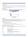
1
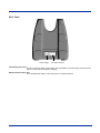
Dolphin® 7200
Mobile Computer
User’s Guide
Disclaimer
Hand Held Products, Inc. (“Hand Held Products”) reserves the right to make changes in specifications and other information
contained in this document without prior notice, and the reader should in all cases consult Hand Held Products to determine
whether any such changes have been made. The information in this publication does not represent a commitment on the part of
Hand Held Products.
Hand Held Products shall not be liable for technical or editorial errors or omissions contained herein; nor for incidental or
consequential damages resulting from the furnishing, performance, or use of this material.
This document contains proprietary information that is protected by copyright. All rights are reserved. No part of this document
may be photocopied, reproduced, or translated into another language without the prior written consent of Hand Held Products.
© 2005 Hand Held Products, Inc. All rights reserved.
Web Address: www.handheld.com
Trademarks
Microsoft, Windows 3.11, Windows 95, Windows 2000, and Windows NT and Excel are trademarks or registered trademarks of
Microsoft Corporation. Dolphin and HomeBase are trademarks or registered trademarks of Hand Held Products. Other product
names mentioned in this document may be trademarks or registered trademarks of their respective companies and are hereby
acknowledged.
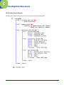
Table of Contents
1
Chapter 1 - Introduction
Safety ...................................................................................................................................................1-2
Required Safety Labels .................................................................................................................1-2
Canadian Notice ............................................................................................................................1-3
CDRH Laser Safety Statement: 7200 Batch .................................................................................1-3
EN 60825-1 Laser Safety Statement .............................................................................................1-3
Regulatory and Safety Agency Approvals ..........................................................................................1-4
Batteries ........................................................................................................................................1-4
Care and Cleaning of the Dolphin .......................................................................................................1-4
Chapter 2 - Getting Started
About the Dolphin 7200 ......................................................................................................................2-1
Accessories for the Dolphin ................................................................................................................2-1
Dolphin 7200 Models ..........................................................................................................................2-3
Dolphin 7200 Batch Terminal.......................................................................................................2-3
Dolphin 7200 RS-232 Terminal....................................................................................................2-3
Dolphin 7200 2D Terminal ...........................................................................................................2-3
Bar Code Symbologies Supported.......................................................................................................2-4
Using Dolphin for the First Time ........................................................................................................2-4
Inserting the Battery Pack .............................................................................................................2-5
Removing the Battery Pack...........................................................................................................2-5
Turning the Dolphin On ................................................................................................................2-5
Turning the Dolphin Off ...............................................................................................................2-6
Chapter 3 - Dolphin 7200 Basics
System Features ...................................................................................................................................3-1
CPU ...............................................................................................................................................3-1
Disk Drives ...................................................................................................................................3-1
Front Panel Features ............................................................................................................................3-1
Light Emitting Diodes (LEDs)......................................................................................................3-1
Liquid Crystal Display (LCD) ......................................................................................................3-1
Speaker..........................................................................................................................................3-1
Using the Alphanumeric Keypad ........................................................................................................3-2
Alphanumeric Key Combinations for Functions and Special Characters.....................................3-3
Using the Numeric Keypad .................................................................................................................3-4
Key Combinations for Functions and Special Characters ............................................................3-5
Entering Alpha and Special Characters ........................................................................................3-5
Display Symbols..................................................................................................................................3-5
Battery Charging Symbol..............................................................................................................3-5
Keyboard Mode.............................................................................................................................3-6
Dolphin® 7200 User’s Guide
iii
Back Panel Features.............................................................................................................................3-6
Laser Engine .................................................................................................................................3-7
Image Engine ................................................................................................................................3-7
Lanyard Eyelet for Optional Wrist Strap ......................................................................................3-7
Battery Well ..................................................................................................................................3-7
Reset Switch..................................................................................................................................3-7
Infrared Communications Port......................................................................................................3-7
Battery Charging Contacts ............................................................................................................3-7
Maintaining the Dolphin's Batteries ....................................................................................................3-8
Internal NiMH Backup Battery.....................................................................................................3-8
NiMH Battery Pack.......................................................................................................................3-8
Resetting the Dolphin Terminal ........................................................................................................3-10
Chapter 4 - Dolphin 7200 RS-232
About Dolphin 7200 RS-232 ...............................................................................................................4-1
Cables ..................................................................................................................................................4-1
Charging the Battery Through the RS-232 Port ..................................................................................4-1
Sending and Receiving Data................................................................................................................4-2
Chapter 5 - Dolphin 7200 2D Mobile Computer
About the Dolphin 7200 2D Mobile Computer...................................................................................5-1
Supported Symbologies .......................................................................................................................5-1
Reading Barcodes ................................................................................................................................5-2
Capturing Images.................................................................................................................................5-3
Lighting Conditions .............................................................................................................................5-3
Dolphin 7200 2D Demo Software .......................................................................................................5-3
Re-Installing the Dolphin 7200 Demo Applications.....................................................................5-3
Dolphin Demo Main Screen .........................................................................................................5-4
F1 - Decoding Demo.....................................................................................................................5-4
F2 - Imaging Demo .......................................................................................................................5-5
F3 - I.Q. Imaging Demo................................................................................................................5-5
Chapter 6 - Dolphin OS and System Development Software
Installation ...........................................................................................................................................6-1
Default Installation Directories .....................................................................................................6-1
Help File, Document and Utility Icons................................................................................................6-2
Dolphin Utilities ..................................................................................................................................6-3
BMP2LCD.EXE ...........................................................................................................................6-3
BURN.EXE...................................................................................................................................6-3
DCOMM2.EXE - Dolphin File Transfer Utility...........................................................................6-3
DWIZARD.EXE (Dolphin Upgrade Wizard)...............................................................................6-4
HBCFG.EXE - HomeBase Configuration Utility.........................................................................6-4
STL.EXE.......................................................................................................................................6-5
YX.EXE ........................................................................................................................................6-5
ZZZ.EXE.......................................................................................................................................6-6
ROM Image...................................................................................................................................6-6
iv
Dolphin® 7200 User’s Guide
Dolphin Application Development......................................................................................................6-7
Compiling Applications for the Dolphin ......................................................................................6-7
Sample Applications .....................................................................................................................6-7
Building the Samples...........................................................................................................................6-8
Compiling the Sample Programs ..................................................................................................6-8
Transferring Files to or from the Dolphin Terminal............................................................................6-9
For a sample, see YX.EXE on page 6-5. ......................................................................................6-9
Sending a File to the Dolphin .......................................................................................................6-9
Sending a File From Dolphin to Your PC.....................................................................................6-9
Sending Files at a Higher Rate......................................................................................................6-9
Using the Dolphin File Transfer Program and YX in Menu Mode ............................................6-10
Dolphin EVS Engine .........................................................................................................................6-11
Dolphin ROM Image and Bootloader ...............................................................................................6-11
Upgrading the Dolphin ROM Image ..........................................................................................6-11
Upgrading the Dolphin Bootloader ...................................................................................................6-12
Chapter 7 - Troubleshooting
Dolphin Terminal and HomeBase .......................................................................................................7-1
Troubleshooting with Dolphin 7200-2D .............................................................................................7-2
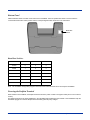
Chapter 8 - Dolphin HomeBase
Hub of the System ...............................................................................................................................8-1
Battery Management .....................................................................................................................8-1
IrDA Optical Communications .....................................................................................................8-1
Convenient Storage .......................................................................................................................8-1
Dolphin 7200 HomeBase Parts and Functions ....................................................................................8-2
Front Panel ....................................................................................................................................8-2
Back Panel.....................................................................................................................................8-3
Side Panels...........................................................................................................................................8-4
Main Communications Port ..........................................................................................................8-4
Multi-HomeBase Port ...................................................................................................................8-4
Charging Batteries in the Dolphin 7200 HomeBase ...........................................................................8-5
Charging a Dolphin Terminal .......................................................................................................8-5
Charging an Additional NiMH Battery Pack ................................................................................8-6
Deep-Cycling the Battery ....................................................................................................................8-6
Communications ..................................................................................................................................8-6
Setting up the Dolphin HomeBase ......................................................................................................8-7
Connecting the Cables ..................................................................................................................8-7
Setting the Configuration Switches...............................................................................................8-7
Setting the Baud Rate....................................................................................................................8-8
Configuring a Single Dolphin 7200 HomeBase ..................................................................................8-8
Version Number ............................................................................................................................8-8
Baud Rate Selection ......................................................................................................................8-8
Creating a Dolphin 7200 HomeBase Network ....................................................................................8-9
How to Daisy Chain the Dolphin HomeBases..............................................................................8-9
Programming Commands .............................................................................................................8-9
Communicating with the Dolphin Terminal......................................................................................8-11
Dolphin® 7200 User’s Guide
v
Chapter 9 - Compact HomeBase
Hub of the System ...............................................................................................................................9-1
Battery Management .....................................................................................................................9-1
IrDA Optical Communications .....................................................................................................9-1
Convenient Storage .......................................................................................................................9-1
Dolphin 7200 Compact HomeBase Parts and Functions.....................................................................9-2
Front Panel...........................................................................................................................................9-2
Back Panel ...........................................................................................................................................9-3
Bottom Panel .......................................................................................................................................9-4
Baud Rate Switches ......................................................................................................................9-4
Powering the Dolphin Terminal ..........................................................................................................9-4
Charging a Dolphin Terminal..............................................................................................................9-5
Deep-Cycling Batteries........................................................................................................................9-5
Mounting the Dolphin 7200 Compact HomeBase ..............................................................................9-5
Desk Mounting:.............................................................................................................................9-5
Wall Mounting: .............................................................................................................................9-6
Setting Up for Communications ..........................................................................................................9-8
Setting up the Dolphin Compact HomeBase .......................................................................................9-8
Connecting the Cables ..................................................................................................................9-8
Communicating with the Dolphin Terminal........................................................................................9-9
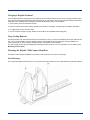
Chapter 10 - Dolphin Vehicle Base
Introduction .......................................................................................................................................10-1
Basic Features....................................................................................................................................10-1
Bottom Panel .....................................................................................................................................10-1
Setting Up the Dolphin VehicleBase ..........................................................................................10-1
Connecting The Serial Cable ......................................................................................................10-1
Supplying Power to the Dolphin VehicleBase............................................................................10-2
Selecting the Baud Rate ..............................................................................................................10-2
Side Panel Features............................................................................................................................10-3
Inserting the Dolphin Terminal into the VehicleBase .......................................................................10-4
Charging Batteries in the VehicleBase ..............................................................................................10-4
Battery Temperatures ..................................................................................................................10-4
Cables for the VehicleBase................................................................................................................10-5
Standard Serial Cable..................................................................................................................10-5
Making Your Own Cable ............................................................................................................10-5
Chapter 11 - Dolphin MultiCharger
Introduction .......................................................................................................................................11-1
Basic Features .............................................................................................................................11-1
Intelligent Battery Charging........................................................................................................11-1
Top Panel ...........................................................................................................................................11-2
Setting Up the Dolphin MultiCharger ...............................................................................................11-2
Supplying Power to the Dolphin MultiCharger ..........................................................................11-2
Inserting the Dolphin Battery Pack .............................................................................................11-3
Charging Batteries in the Dolphin MultiCharger ..............................................................................11-3
Battery Temperatures ..................................................................................................................11-3
vi
Dolphin® 7200 User’s Guide
Servicing the Battery Pack ................................................................................................................11-3
Troubleshooting.................................................................................................................................11-4
Declaration of Conformity.................................................................................................................11-5
Chapter 12 - Customer Support
Product Service and Repair ...............................................................................................................12-1
Online Product Service and Repair Assistance...........................................................................12-2
Technical Assistance .........................................................................................................................12-2
Online Technical Assistance .......................................................................................................12-2
Limited Warranty ..............................................................................................................................12-3
Appendix A - Technical Specifications
Dolphin 7200 Terminal Specifications...............................................................................................A-1
Appendix B - Bar Code Samples
Code 39 (Code 3 of 9).................................................................................................................. B-1
Code 128 ...................................................................................................................................... B-1
UPC-A.......................................................................................................................................... B-1
Interleave 2 of 5 (I2of5) ............................................................................................................... B-1
Appendix C - Decoding Demo Menu Layout
2D Decoding Demo Diagram ............................................................................................................. C-1
2D Decoding Demo Screen Shots ...................................................................................................... C-2
Setup Menu .................................................................................................................................. C-2
Display Options Menu ................................................................................................................. C-2
Symbologies................................................................................................................................. C-2
Decoding Options ....................................................................................................................... C-3
Decode Mode ............................................................................................................................... C-3
Centering Window ....................................................................................................................... C-4
ALD Window ..................................................................................................................................... C-5
Appendix D - IQ Imaging Test Target
Appendix E - GS-DOS Commands
Dolphin® 7200 User’s Guide
vii
Internal Commands Supported by GS-DOS....................................................................................... E-1
HELP............................................................................................................................................ E-1
BREAK ........................................................................................................................................ E-1
CALL ........................................................................................................................................... E-1
CD (CHDIR) ................................................................................................................................ E-2
CLS .............................................................................................................................................. E-2
COPY ........................................................................................................................................... E-2
CTTY ........................................................................................................................................... E-2
DATE ........................................................................................................................................... E-2
DEL (ERASE or ERA) ................................................................................................................ E-2
DELAY ........................................................................................................................................ E-2
DIR............................................................................................................................................... E-2
ECHO........................................................................................................................................... E-3
EXIT............................................................................................................................................. E-3
GOTO........................................................................................................................................... E-3
IF .................................................................................................................................................. E-3
MD (MKDIR) .............................................................................................................................. E-3
PATH ........................................................................................................................................... E-3
PAUSE ......................................................................................................................................... E-3
PROMPT...................................................................................................................................... E-4
RD (RMDIR) ............................................................................................................................... E-4
REM ............................................................................................................................................. E-4
REBOOT...................................................................................................................................... E-4
REN.............................................................................................................................................. E-4
SHIFT........................................................................................................................................... E-4
SET............................................................................................................................................... E-4
SHIFT........................................................................................................................................... E-5
SYNC ........................................................................................................................................... E-5
TIME ............................................................................................................................................ E-5
TRUENAME ............................................................................................................................... E-5
TYPE............................................................................................................................................ E-5
VER.............................................................................................................................................. E-5
VERIFY ....................................................................................................................................... E-5
VOL ............................................................................................................................................. E-5
Appendix F - Declarations of Conformity
viii
Dolphin® 7200 User’s Guide
1
Introduction
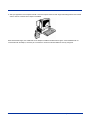
Congratulations on the purchase of your new Dolphin 7200 mobile computer!
You have made a wise choice in selecting the Dolphin 7200, a device known worldwide for its ergonomic shape, light weight,
versatility and single-handed data collection features.
Ergonomics
The patented shape allows true, one-handed operation and fits either hand comfortably. Built to last, the Dolphin's ruggedly built
case houses a 386 microprocessor and DOS operating system that is easily programmable with standard programming tools like
Microsoft Visual C/C++, Borland C/C++, or Visual Basic.
Durability
Dolphin is one of the most durable devices available, and is designed to withstand repeated five-foot drops onto a concrete floor.
It also resists extreme temperatures, humidity levels and dust conditions.
Features
The Dolphin's basic features include long-lasting Nickel Metal Hydride (NiMH) batteries, a large, easy-to-read 8 line x 20
character backlit display that can display text or graphics, a natural scan and viewing angle, and two keypad options.
Multiple Configurations
The multiple configurations available for the Dolphin 7200 make it one of the most versatile terminals in the automatic data
collection industry. The terminal may be equipped with a scan engine capable of reading all standard bar code symbologies.
The Dolphin 7200 RS-232 terminal features a micro-DB9 RS-232 for serial data input/output and charging in addition to the
infrared port.
The Dolphin 7200-2D terminal comes available with the IMAGETEAM™ 4250 Image Engine, a low power, high-resolution digital
image engine for omni-directional and auto-discrimination reading and decoding of linear barcodes, stacked linear (PDF417) and
2D matrix codes. The image engine functions like a digital camera and also provides Optical Character Recognition (OCR)
functionality.
Load up the Dolphin with your custom software application and the ultimate data collection solution for your business fits in the
palm of your hand.
Dolphin® 7200 User’s Guide
1-1
Safety
The Dolphin 7200 handheld computer/bar code scanner meets or exceeds the requirements of all applicable standards
organizations for safe operation. However, as with any electrical equipment, the best way to ensure safe operation is to know the
possible risks. The following safety guidelines are designed to protect both you and others around you. Please read them
carefully before using your Dolphin.
Required Safety Labels
Dolphin 7200 terminals use a low power Visible Laser to scan bar codes. Short-term exposure to CDRH Class II laser light is not
known to be harmful. As with any bright light source, such as the sun, you should avoid direct eye exposure.
Locations
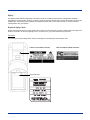
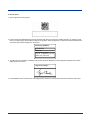
The following are required safety labels, as they should appear on the back panel of the Dolphin 7200:
Label for Laser Batch Terminals
Label for Dolphin 7200-2D Terminals
Product ID Label
1-2
Dolphin® 7200 User’s Guide
Statement of Agency Compliance
This device complies with part 15 of the FCC Rules. Operation is subject to the following two conditions: (1) this device may not
cause harmful interference, and (2) this device must accept any interference received, including interference that may cause
undesired operation.
FCC Class A Compliance Statement
This equipment has been tested and found to comply with the limits for a Class A digital device, pursuant to part 15 of the FCC
Rules. These limits are designed to provide reasonable protection against harmful interference when the equipment is operated
in a commercial environment. This equipment generates, uses, and can radiate radio frequency energy and, if not installed and
used in accordance with the instruction manual, may cause harmful interference to radio communications. Operation of this
equipment in a residential area is likely to cause harmful interference, in which case the user will be required to correct the
interference at his own expense.
Caution: Any changes or modifications made to this device that are not expressly approved by Hand Held Products may void
the user's authority to operate the equipment.
Note: To maintain compliance with FCC Rules and Regulations, cables connected to this device must be shielded cables, in
which the cable shield wire(s) have been grounded (tied) to the connector shell.
Canadian Notice
This equipment does not exceed the Class A limits for radio noise emissions as described in the Radio Interference Regulations
of the Canadian Department of Communications.
Le present appareil numerique n'emet pas de bruits radioelectriques depassant les limites applicables aux appareils numeriques
de la classe A prescrites dans le Reglement sur le brouillage radioelectrique edicte par le ministere des Communications du
Canada.
CDRH Laser Safety Statement: 7200 Batch
This product complies with US DHHS 21 CFR J Part 1040.10. This product is a CLASS II LASER PRODUCT with a maximum
output of 1.0 mW at 670 nanometers and continuous wave.
EN 60825-1 Laser Safety Statement
This product is classified as a CLASS 2 LASER PRODUCT with a maximum output of 1.0 mW at 670 nanometers per EN 608251:1994, Issue 2, June 1997.
Dolphin® 7200 User’s Guide
1-3
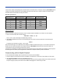
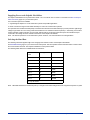
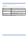
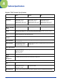
Regulatory and Safety Agency Approvals
Parameter
Specification
U.S.A.
FCC Part 15, Class A
Canada
IEC 0003
Europe
EN 55022 (CISPR22) Class A
EN 55024
The CE mark on the product indicates that the system has been tested to and conforms with the provisions noted within
the 89/336/EEC Electromagnetic Compatibility Directive and the 73/23/EEC Low Voltage Directive.
For further information please contact:
Hand Held Products, Inc.
5627 BT Eindhoven
The Netherlands
Hand Held Products shall not be liable for use of our product with equipment (i.e., power supplies, personal computers, etc.) that
is not CE marked and does not comply with the Low Voltage Directive.
Batteries
• Use only the battery supplied with your Dolphin or a replacement battery supplied, recommended, or approved by Hand Held
Products.
• Replace a defective battery immediately as it could damage the Dolphin terminal.
• Never throw a used battery in the trash. It contains heavy metals and should be recycled according to local guidelines.
• Don't short-circuit a battery or throw it into a fire. It can explode and cause severe personal injury.
• Excessive discharge damages a battery. Recharge the battery when your Dolphin indicates low battery power.
• Although your battery can be recharged many times, it will eventually be depleted. Replace it after the recommended usage
period (about 500 charge cycles for the 1500 mAh NiMH battery) or if the battery does not hold a charge.
• If you are not sure the battery or charger is working properly, please send it to Hand Held Products or an authorized Hand
Held Products service center, for inspection.
The Dolphin handheld computer/bar code scanner meets or exceeds all applicable standards and has been manufactured to the
highest level of quality.
Care and Cleaning of the Dolphin
When needed, clean the laser engine window and the LCD display with a clean non-abrasive, lint-free cloth.
1-4
Dolphin® 7200 User’s Guide
2
Getting Started
About the Dolphin 7200
The Dolphin is a handheld computer and imager/bar code scanner with a 386 33 MHz microprocessor that runs with GS-DOS
and is PC-compatible and is designed for easy, single-handed data collection.
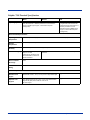
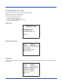
Accessories for the Dolphin
The Dolphin 7200 is part of a data collection system that includes accessories specifically designed for vehicle, desktop and hub
operations. Accessories available include serial and networkable communications/charging cradles, serial communications/
charging cables, desktop "gang chargers" and vehicle mounted charging/communication cradles.
You can use these accessories with the Dolphin:
Dolphin HomeBase™
Dolphin Compact HomeBase™
Charges one Dolphin terminal and one extra battery pack in its
auxiliary batter well; includes power adapter for proper current.
For more information, see Dolphin HomeBase on page 8-1.
For more information, see Compact HomeBase on page 9-1.
Dolphin HomeBase Power Adapter
Replacement power adapter for Dolphin HomeBase.
Note: Use only power adapters approved for use by Hand Held
Products. Failure to do so may result in improper
operation or damage to the unit.
Dolphin MultiCharger™
10-slot battery charger designed specifically for Dolphin NiMH
battery packs that charges and reconditions 10 batteries in
under four hours. Supports 90-264V.
For more information, see Dolphin MultiCharger on page 11-1.
Dolphin® 7200 User’s Guide
2-1
Dolphin VehicleBase™
Battery charging and/or communications cradle designed for
in-transit applications. Mounted inside a vehicle, this cradle
provides connectivity to any RS-232 serial device including
printers, radio modems, GPS, on-board computers and vehicle
monitoring systems.
For more information, see Dolphin Vehicle Base on page 10-1.
Wrist Strap for Dolphin
Holster
A convenient way to carry the Dolphin.
Note: Lanyard ring for attaching strap not available with the
Dolphin 7200 RS-232.
Another convenient way to carry the Dolphin. Available in
leather or cordura, a rugged synthetic fabric.
NiMH Battery Pack
Nickel Metal Hydride (NiMH) 3.6V rechargeable battery for the
Dolphin.
For more information, see Dolphin MultiCharger on page 11-1.
Communication/Charging Cable for
Dolphin 7200 RS-232
Connects the Dolphin 7200 RS-232 terminal directly to host
computer using micro-DB9 to DB9 serial cable, and recharges
the battery using the Universal Power Adapter PS9U-11.
6' RS-232 Serial Cable
Connects the Dolphin HomeBase to your desktop PC.
Note: Use your Dolphin only with accessories supplied, recommended or approved by Hand Held Products, Inc. Use of nonapproved accessories can be dangerous and will invalidate any warranty or liability claims.
2-2
Dolphin® 7200 User’s Guide
Dolphin 7200 Models
Hand Held Product's family of Dolphin 7200 handheld portable data collection terminals includes these models:
Dolphin 7200 Batch Terminal
The Dolphin 7200 Batch terminal is a DOS programmable handheld computer/bar code scanner with a unique, ergonomic shape
designed for single-handed use. The basic terminal has 2MB RAM and 8MB FLASH EEPROM memory. It also features an IrDA
infrared transceiver for data communications.
Options
•
•
•
•
•
•
36-key alphanumeric keypad or 20-key numeric keypad with shifted alpha characters
Standard High Performance, Long-Range or High Density scan engines
2 MB RAM with 8 MB non-volatile FLASH memory (expandable to 16 MB on Dolphin 7200 Batch only)
No scan engine (manual entry only)
Integrated image engine
Micro-DB9 RS-232 serial port
Dolphin 7200 RS-232 Terminal
The Dolphin 7200 RS-232 terminal is identical to the Dolphin 7200 Batch terminal except that it features a micro-DB9 RS-232
port on the back panel for serial data input/output and charging.
Dolphin 7200 2D Terminal
The Dolphin 7200 2D terminal is identical to the Dolphin 7200 Batch terminal with IQ Imaging™. IQ Imaging offers a suite of
features to increase productivity when reading all major linear, stacked linear (PDF417), and matrix bar code symbologies, OCR
fonts, and performing image capture. IQ Imaging features the IMAGETEAM™ 4250 Image Engine, a low power, high-resolution
digital image engine for omni-directional and auto-discrimination reading and decoding.
Dolphin® 7200 User’s Guide
2-3
Bar Code Symbologies Supported
1D Linear Codes:
Code 3 of 9, Interleaved 2 of 5, Code 11, MSI, UPC A, UPC EO, UPC EI, EAN/EAN13, Codabar,
Code 128, Code 93, UPC
2D Codes:
PDF417, microPDF, Maxicode, Datamatrix, Aztec, QR Code, Code 49
Composite Codes:
RSS-14, CODABLOCK, AZTEC MESA
OCR Codes:
OCR A and OCR B
Postal Codes:
Postnet and most international 4 state codes, PLANET CODE, BPO 4 STATE, CANADIAN 4 STATE,
DUTCH POSTAL, AUSTRALIAN 4 STATE, JAPANESE POSTAL
Using Dolphin for the First Time
This section will show you how to:
1. Be sure that you've received all items included with your Dolphin order
2. Charge the battery
3. Turn the Dolphin on and off
4. Set the date and time
Note: Be sure to keep the original carton and packaging in the event that the Dolphin terminal or Dolphin HomeBase should
need to be returned for service.
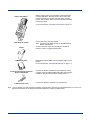
Step 1. Checking Your Package
If you ordered a Dolphin 7200 Batch or 2D terminal, inspect the package to see that the following standard items and accessories
(if ordered) are included:
•
•
•
•
Dolphin 7200 terminal
Battery (1500 mAh, Nickel Metal Hydride (NiMH)
Dolphin 7200 HomeBase
AC-DC Power Adapter for Dolphin HomeBase
If you ordered a Dolphin 7200 RS-232 terminal, inspect the package to see that the following standard items and accessories (if
ordered) are included:
•
•
•
•
Dolphin 7200 RS-232 terminal
Battery - 1500 mAh, Nickel Metal Hydride (NiMH)
Dolphin 7200 RS-232 Communication/Charging Cable
AC-DC Universal Power Adapter
Step 2. Charging the Battery
!
Use only 3.6V battery packs provided by Hand Held Products. The use of any other battery pack in the Dolphin terminal
will void your warranty and may result in damage to the Dolphin terminal or battery.
!
Although the Dolphin 7200 terminal is received with the battery inserted, it is NOT ready for charging and/or deepcycling. Remove the plastic insulator located between the terminal and battery connectors. Failure to remove the
insulator may result in damages to the terminal.
The terminal's NiMH battery is not conditioned at the factory and is shipped discharged of all power and inserted in the Dolphin
terminal. For maximum battery life, Hand Held Products recommends that you deep-cycle the battery twice before initial use.
To deep-cycle, insert the battery into the HomeBase auxiliary battery well. Then, push and hold the Service Aux Batt button for
at least four seconds. For more information, see Deep-Cycling the Battery on page 8-6. You may also use the CycleBat software
utility to deep-cycle the battery. This utility is available for download from the Partners Area of www.handheld.com.
Note: For maximum battery life, Hand Held Products recommends that you deep-cycle (service) the battery twice before initial
use and then, once a month thereafter.
2-4
Dolphin® 7200 User’s Guide
If you have a Dolphin 7200 RS-232 terminal and are using the communication/charging cable instead of a HomeBase to charge
the battery, charge the terminal for 24 hours before initial use.
After deep cycling the battery, you may charge the battery using one of these methods:
• Place the battery in the auxiliary battery well on the Dolphin HomeBase. Time to Charge: 3 hours
• Place the battery in the 10-slot Dolphin MultiCharger. Time to Charge: 3 hours
• Install the battery in the Dolphin, place the Dolphin in the HomeBase and connect the HomeBase to an external power source.
Time to Charge: 5 ½ hours
• Plug the micro-DB9 end of the communication/charging cable into Dolphin 7200 RS-232 terminal's RS-232 port and connect
to an external power source. Time to Charge: 5 ½ hours
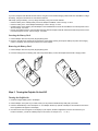
Inserting the Battery Pack
1. Hold the Dolphin with the front panel (keypad) facing down.
2. Insert the end without the locking tab into the bottom of the battery opening and snap the battery into place with a hinging
motion. The battery case serves as the back cover of the Dolphin.
Removing the Battery Pack
1. Hold the Dolphin with the front panel (keypad) facing down.
2. Push the locking tab on the battery pack down and pull the battery out from the Dolphin terminal with a hinging motion.
Step 3. Turning the Dolphin On And Off
Turning the Dolphin On
1. Install the charged battery pack in the Dolphin.
2. Hold the Dolphin in the palm of your hand so that you can press the ON/SCAN key easily with your thumb.
3. Press the ON/SCAN key to turn the Dolphin on. Your Dolphin will boot up just like a desktop PC and the title screen for the
Demo Application will appear on the display.
4. If the title screen does not appear on the display of your Dolphin, the Demo Application has been removed from your
terminal. Therefore, you will see a DOS prompt on the screen; for example: C:\ or A:\ .
Dolphin® 7200 User’s Guide
2-5
Note: If using the Dolphin for first time or if the terminal has been without a battery pack for more than 30 minutes and you are
now inserting a battery, you may receive a CMOS error when the terminal boots up. Don't worry, the terminal is OK. This
simply means that the internal back-up battery needs to be recharged and the date and time need to be reset. To recharge
the internal backup battery and reset the date and time, insert a fully charged battery in the Dolphin and then use the DOS
date and time function to set the correct date and time. The internal back-up battery requires a minimum of 5 hours of
charging time in order to perform and maintain the system as described on page 30.
Turning the Dolphin Off
The Dolphin is never actually turned off. To conserve power, the Dolphin goes into "sleep mode" when it is inactive for a
programmed period of time as defined by your application. The screen is blank when the Dolphin is in "sleep mode."
Step 4. Setting the Date and Time
Use the DOS date and time function to set the correct date and time for your Dolphin terminal.
To Set the Date on an Alphanumeric Terminal:
1. Enter DATE at the Dolphin's DOS prompt.
2. Press NUM LOCK to put the Dolphin in numeric mode.
3. Enter the new date mm-dd-yyyy.
4. Press ENTER.
To Set the Date on a Numeric Terminal:
1. Press SHIFT to put the Dolphin in alpha mode.
2. Enter DATE at the Dolphin's DOS prompt; see Using the Numeric Keypad on page 3-4.
3. Press SHIFT to put the Dolphin back in numeric mode.
4. Enter the new date mm-dd-yy.
5. Press ENTER.
To Set the Time
To enter the new time, enter TIME at the Dolphin's DOS prompt instead of DATE and follow the directions for the Dolphin model
you are using.
2-6
Dolphin® 7200 User’s Guide
3
Dolphin 7200 Basics
System Features
CPU
The Dolphin's computing power is provided by a highly integrated AMD ELAN SC310 386SX 33 MHz microprocessor.
Disk Drives
The Dolphin contains two disk drives that provide storage for system files, applications, and data. A third drive is also present if
you purchase the FLASH expansion option.
Drive A
Drive A contains a 120K executable FLASH EEPROM to store system utilities and to initialize the boot
process. This drive is read-only and is not usable by the developer/end-user.
Drive C
Drive C is an 8MB FLASH virtual hard drive used for program and data storage. Drive C is an image
of the Drive A and not a physical drive.
Drive D
If you add the expanded memory module to your Dolphin Batch terminal, it will appear as Drive D.
Eight MB of additional FLASH memory can be added via the FLASH expansion module. This option
is available in the Dolphin Batch terminal only.
Front Panel Features
This section describes features on the Dolphin's front panel. The alphanumeric and numeric Dolphins have identical back panels.
Light Emitting Diodes (LEDs)
The red LED located at the upper right corner of the LCD display is labeled SCAN. This LED illuminates when the user presses
the ON/KEY key and activates the scan engine.
The green LED located at the upper left corner of the LCD display is labeled DECODE. This LED illuminates when the bar code
software successfully decodes a bar code. Both LEDs are software programmable.
Liquid Crystal Display (LCD)
The alphanumeric, scrollable LCD consists of nine rows with 20 character positions per row and 119 x 73 graphics pixels, which
are software addressable. The electroluminescent backlight allows you to view the display in low light conditions. To conserve
power, the backlight is automatically turned off after 30 seconds. The on/off function and contrast is software programmable.
Note: The ninth row is used for system icons and application-defined icons.
Speaker
The Dolphin Batch terminal's internal speaker emits a sound level of 80dB at 10 cm.
Dolphin® 7200 User’s Guide
3-1
Using the Alphanumeric Keypad
The Dolphin's alphanumeric, splash-resistant keypad has 36 epoxy coated keys. The keyboard's yellow background enhances
the readability of the numeric and special character keys.
ODE
DEC
The Dolphin's ON/SCAN key
"wakes" the terminal from
sleep mode. Its position also
allows convenient one-handed
bar code scanning.
SCA
N
D O L P H I N
SINGLE-HANDED
POCKET-SIZE
LASER SCANNER
The SHIFT key toggles the
Dolphin from alpha to numeric
mode and back and, in
combination with other keys,
allows you to enter special
characters.
DOS PLATFORM
POWER MGMT
INFRA RED COMM
F1
F2
F4
The F1, F2, F3 and F4 keys are
user-definable function keys
and may be programmed for a
variety of functions.
ESC
SHIFT
CLR
The ENTER key confirms
data entry.
F3
ON
SCAN
A
F
K
P
7
4
1
=
ENTER
B
G
L
Q
8
5
2
0
C
H
M
R
BKSP
9
6
3
.
D
I
N
S
E
+
-
The BKSP key moves you to
move the cursor back one
space each time the key is
pressed.
J
O
T
SPC
U
The NUM LOCK key toggles
between the alphabetic and
numeric modes.
3-2
NUM
LOCK
V
W
Z
X
Y
LIGHT
The LIGHT key toggles the
LCD backlight on and off.
Dolphin® 7200 User’s Guide
Alphanumeric Key Combinations for Functions and Special Characters
Use the key combinations listed below to access certain keypad functions or to use special characters that are not defined on
the Dolphin keypad.
Key Combinations
Functions or Character
ESC (SHIFT + BKSP)
The ESC function performs a cancel action.
SPC (SHIFT + U)
The SPC function moves the cursor forward one space
at a time.
CLR (SHIFT + A)
The CLR function erases the line of data just entered,
if the ENTER key has not yet been pressed.
SHIFT + F
#
SHIFT + K
@
SHIFT + P
&
SHIFT + V
$
SHIFT + W
%
SHIFT + X
!
SHIFT + Y
\
SHIFT + Z
:
SHIFT + E
*
SHIFT + J
/
SHIFT + LIGHT
Changes Contrast
Dolphin® 7200 User’s Guide
3-3
Using the Numeric Keypad
The Dolphin's numeric, splash-resistant keypad has 20 epoxy coated keys. The large, amber-color keys are large, easy-to-read,
and comfortably spaced to help prevent errors in data entry. Digits can be entered without using the shift key.
Though designed primarily for numeric data entry, you can use the SHIFT key to switch between numeric and alpha modes or
use special characters.
DEC
The Dolphin's ON/SCAN key
"wakes" the terminal from
sleep mode. Its position also
allows convenient one-handed
bar code scanning.
SCA
ODE
D O L P H I N
SINGLE-HANDED
POCKET-SIZE
LASER SCANNER
F1
F3
ON
SCAN
-
-
F2
SHIFT
F4
=
ESC
ENTER
BKSP
7
D
E
F
J
K
L
4
S
T
U
1
.
A
B
C
%
$
?
3-4
DOS PLATFORM
POWER MGMT
INFRA RED COMM
+
The SHIFT key toggles the Dolphin
from alpha to numeric mode and back
and, in combination with other keys,
allows you to enter special
characters.
The ENTER key
confirms data entry.
N
8
G
H
I
9
M
N
O
5
P
Q
R
6
V
W
X
2
Y
Z
,
3
\
:
>
0
SP
LIGHT
CONTR
CALC
The F1, F2, F3 and F4 keys are
user-definable function keys
and may be programmed for a
variety of functions.
The BKSP key moves you to
move the cursor back one
space each time the key is
pressed.
The SP (space) key moves the
cursor forward one key at a
Dolphin® 7200 User’s Guide
Key Combinations for Functions and Special Characters
Key Combination
Function
ESC (SHIFT + BKSP)
The ESC function performs a cancel action.
LIGHT (SHIFT + SP)
This action toggles the LCD backlight on and off. Press the SHIFT key to put the Dolphin
in alpha mode and press the SP key once.
CONTR (SHIFT + SP+SP)
The CONTR function adjusts the LCD contrast. Press the SHIFT key to put the Dolphin
in alpha mode and press the SP key twice. Use the F1 and F2 keys to adjust the contrast
up or down. When finished, press the BKSP key.
CALC
This function is undefined. However, it can be programmed by a custom application to
load a calculator utility.
Entering Alpha and Special Characters
1. Press the SHIFT key to switch the numeric keypad to alpha mode. This is indicated by the ABC symbol indicated on the
LCD. Each numeric key, as well as the "." Key has three letters or symbols listed beside it.
2. To display the first letter or symbol next to a key, press the numeric key once.
3. To display the second letter/symbol, press the key next to the desired letter/symbol twice within one second.
4. To display the third letter/symbol, press the key next to the desired letter/symbol three times within one second.
For example, to enter a letter "G" into the Dolphin terminal, press the SHIFT key to put the Dolphin in alpha mode. Press the "9"
key once and the letter "G" will be entered.
To enter a "T" into the Dolphin terminal, press the SHIFT key to put the Dolphin in alpha mode. Press the "1" key twice and the
letter "T" will be entered.
Display Symbols
Here is a list of the symbols that can appear on the LCD display of your Dolphin and their meanings.
Battery Charging Symbol
Located in lower left-hand corner of the LCD, this symbol indicates the battery charge. When this symbol is blinking, the battery's
charge is critically low and you should recharge it as soon as possible.
Note: The battery charge level symbol is only an estimate of the remaining battery life.
For information on battery capacity and charging, see the section on Maintaining the Dolphin's Batteries later in this chapter.
Icon
Indicates
Blinks while main battery in the Dolphin terminal is charging in the Dolphin 7200 HomeBase.
Located in lower left-hand corner of the LCD.
Blinks while the main battery in the Dolphin terminal is discharging when using the battery deepcycling utility program.
Switches from a blinking arrow to this blinking check when the unit has completed charging in the
HomeBase.
Shows the charge level of the Dolphin terminal's main battery when the terminal is in use. The
charge symbol decreases in size as the charge level drops.
Dolphin® 7200 User’s Guide
3-5
Keyboard Mode
These symbols indicate which mode is operational on the keyboard and are located next to the battery charge indicator. Use the
SHIFT key to toggle between numeric to alpha mode on Dolphin.
Icon
Indicates
Which means that …
Alpha mode
Alphabetic characters are active
Numeric mode
Numeric characters are active
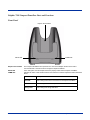
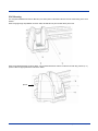
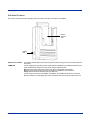
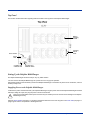
Back Panel Features
This section describes features on the Dolphin's back panel. The alphanumeric and numeric Dolphins have identical back panels.
Laser/Image Engine Window
Micro-DB9 RS-232 (Dolphin
7200 RS-232) or
Lanyard Eyelet (not available
on Dolphin 2D)
Reset Switch
Battery Well
Battery Charging
Contacts
Infrared Communications Port
3-6
Dolphin® 7200 User’s Guide
Laser Engine
The Dolphin 7200 is currently available with four scanning options:
•
•
•
•
Standard range
Long range
High density scanning
No scan engine
The laser engine converts reflected light into a digital pattern that represents the bar code data. A clear window covers the laser
engine to protect it from dust and dirt.
Image Engine
The Dolphin 7200 2D terminal is available with the following imaging options:
• Standard image engine: scans 2 to 9 in. (5 to 23 cm)
• High-Density: scans 2 to 4 in. (5 to 12 cm)
• LX image engine: scans 2 to 15 in. (5 to 38 cm) on low density bar codes
Lanyard Eyelet for Optional Wrist Strap
This feature allows a strap to be attached to the Dolphin terminal so that it can be conveniently secured around the wrist or
hooked on to a belt. Not available on the Dolphin 7200 2D or the Dolphin 7200 RS-232 terminals.
Battery Well
The battery well is a recessed area on the back of the Dolphin that holds the 3.6V battery pack.
Reset Switch
The Reset Switch is located inside the Dolphin terminal and is accessible through a small opening within the battery well. To
reset the Dolphin, remove the label covering the opening and press the reset switch with a small blunt object such as a paper clip.
Note: Under normal circumstances, you should never need to reset your Dolphin terminal.
Infrared Communications Port
The Infrared Communications Port allows the Dolphin to communicate through the Dolphin HomeBase to a host serial device.
Battery Charging Contacts
When the Dolphin is placed in the main well of the Dolphin HomeBase, the Dolphin's battery pack is charged through these
contacts.
Dolphin® 7200 User’s Guide
3-7
Maintaining the Dolphin's Batteries
!
Although the Dolphin 7200 terminal is received with the battery inserted, it is NOT ready for charging and/or deepcycling. Remove the plastic insulator located between the terminal and battery connectors. Failure to remove the
insulator may result in damages to the terminal.Use only the 3.6V battery packs provided by Hand Held Products. The
use of any other battery pack in the Dolphin 7200 terminal will void your warranty and may result in damage to the
Dolphin terminal or battery.
There are two batteries in the Dolphin:
1. Internal NiMH Backup Battery - Located inside the Dolphin, this battery backs up the RAM and clock when the NiMH main
battery is discharged or removed from the terminal.
2. NiMH Battery Pack - Inserted into the back panel, the battery pack is the primary power source for operating the Dolphin.
Internal NiMH Backup Battery
The Dolphin's internal backup battery prevents the terminal from being reset if you need to remove and replace the main battery
pack. The battery retains RAM data and allows the real-time clock to remain operational for up to 30 minutes when the battery
pack is removed. If the internal back-up battery becomes discharged of power, it requires a minimum of 5 hours of charging time
in order to perform and maintain the system as described above.
The internal backup battery is charged by the Dolphin's main battery pack. If the terminal is left without the main battery pack for
more than 30 minutes, the internal backup battery needs to be recharged.
Note: Data and programs on Drives C and D remain safe even if the internal backup battery fails. However, you must reset the
real-time clock using the DOS Time and Date function.
Guidelines
Follow these guidelines to maximize the life of the Dolphin's backup battery:
• Keep a charged NiMH battery pack in the Dolphin. The internal battery will prematurely discharge if there is not at least a
partially charged battery in the terminal.
• Put the Dolphin in the HomeBase when the terminal is not in use.
Note: Return the Dolphin to an authorized service center when the internal battery needs to be replaced.
NiMH Battery Pack
The 3.6V, 1500 mAh Nickel-Metal-Hydride (NiMH) battery pack is the primary power source for the Dolphin. Other Nickel-MetalHydride batteries may be approved by Hand Held Products, Inc. to work with your Dolphin. Contact Hand Held for more
information.
The 1500 mAh NiMH battery is designed to operate in temperature range of -10 to 50 C (14 to 122 F). For maximum performance,
charge the batteries between 10 and 35 C (50 and 95 F).
!
Although the Dolphin 7200 terminal is received with the battery inserted, it is NOT ready for charging and/or deepcycling. Remove the plastic insulator located between the terminal and battery connectors. Failure to remove the
insulator may result in damages to the terminal.
Performance specifications for a fully charged 1500 mAh NiMH battery (using power management function calls within
application):
• Up to 20 hours of usage in a Dolphin Batch terminal with a full battery charge
• Up to 20 hours of usage in a Dolphin 2D terminal with a full battery charge
Keep a charged battery pack in the Dolphin at all times to conserve the internal back-up battery. When you remove a battery
pack, insert another battery pack in the Dolphin. The internal battery will prematurely discharge if there is not at least a partially
charged battery in the terminal.
3-8
Dolphin® 7200 User’s Guide
Servicing the Battery Pack
For maximum battery life, Hand Held Products recommends that you deep-cycle the battery twice before initial use. To deep
cycle, insert the battery into the HomeBase auxiliary battery well. Then, push and hold the Service Aux Batt button for at least 4
seconds. For more information, see Charging an Additional NiMH Battery Pack on page 8-6.
You may also deep cycle the battery using the CycleBat battery utility conditioning software which is available from the Partners
area of the Hand Held Products web site www.handheld.com. More information on this utility is available from the help file that
comes with the software.
Note: For maximum battery life, Hand Held Products recommends that you deep-cycle (service) the battery twice before initial
use and then, once a month thereafter.
Hand Held Products also recommends that you service, or calibrate the battery once per month. For details, see Servicing the
Battery Pack on page 11-3.
Charging the Battery Pack
You can recharge an individual battery pack using the auxiliary battery well of the Dolphin HomeBase, or the Dolphin 10-Slot
MultiCharger.
Note: Keep a charged battery pack in the Dolphin at all times to conserve the internal back-up battery.
For details about the Dolphin HomeBase, see Charging Batteries in the Dolphin 7200 HomeBase on page 8-5.
For details about the Dolphin MultiCharger, see Charging Batteries in the Dolphin MultiCharger on page 11-3.
Storing Battery Packs
To maintain top performance from batteries, follow the guidelines below when storing them:
• Avoid storing batteries outside of the specified range of -4 to 104° F (-20 to 40°C) or in extremely high humidity.
• For prolonged storage, do not keep batteries stored in the terminal.
• During long-term storage, battery deactivation may tend to occur which may cause charging to stop early during recharging
after storage. Charging and discharging the battery several times can handle this issue. Also, the first charging after prolonged
storage may yield a lower than normal capacity. While this will vary depending on the storage conditions, charging and
discharging the battery several times will almost completely restore capacity.
Dolphin® 7200 User’s Guide
3-9
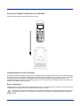
Resetting the Dolphin Terminal
Under normal circumstances, you should not need to reset the Dolphin terminal. However, if required, you can reset the terminal
with one of the following methods:
1. Perform the Three Key Reset.
The Dolphin terminal can be reset by pressing and releasing the SHIFT, ON/SCAN and BKSP keys. All three keys must be
held down and released at the same time.
OR
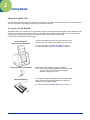
2. Press the Reset Switch.
The reset switch is located in the battery compartment of the Dolphin terminal.
Reset
Switch
Use the tip of an unfolded paper clip (or other similar blunt object) to gently press the reset switch.
The recess hole for the reset switch may be covered with a small plastic cover. This cover must be removed and placed back
in position after accessing the reset switch.
OR
3. Remove the main battery.
If the methods described above are not successful, the Dolphin terminal may be reset by removing the main battery for an
extended period of time. The terminal will reset when the Dolphin's internal backup battery is completely drained of power. This
process may take up to 5 hours.
3 - 10
Dolphin® 7200 User’s Guide
4
Dolphin 7200 RS-232
About Dolphin 7200 RS-232
The Dolphin 7200 handheld computer with micro-DB9 RS-232 port is a compact, high performance data collection terminal with
standard connectivity at a low cost. Through the terminal's micro-DB9 RS-232 port, the Dolphin 7200 can be connected to a host
computer to send and receive data.
The terminal's battery can be recharged through the RS-232 port using the Dolphin 7200 communication/charging cable and a
power adapter or the Dolphin HomeBase charging/communications cradle.
The Dolphin 7200 RS-232 can also connect to self-powered, RS-232-compliant peripherals, such as external modems and
printers, GPS receivers, electronic scales, and various input devices via the micro-DB9 RS-232 port. Wireless IrDA connectivity
remains available, allowing users to connect with IrDA-compliant printers through the IR port.
Cables
The following table shows pinout for the Dolphin 7200 terminal's micro-DB9 RS-232 port.
Note: The " RF_card" function call will turn off the 5V supplied on pin 9 of the 7200 RS-232 non-scan units. This already exists
in OS4.1 API.
The pin-out configuration is as follows:
Pin #
Signal
Description
Direction
1
VCHG
9V Charging Voltage
Input
2
TXD
Transmit Data
Output
3
RXD
Receive Data
Input
4
DSR
Data Set Ready
Input; looped to Pin 6
5
GND
Ground
6
DTR
Data Terminal Ready
Output; looped to Pin 4
7
CTS
Clear To Send
Input
8
RTS
Request To Send
Output
9
/
No Connectadd +5VDC
Non scanning (blind) models only
Charging the Battery Through the RS-232 Port
Before initial use, the Dolphin 7200 RS-232 terminal should be charged for 24 hours.
1. Plug the adapter into electrical outlet.
2. Insert a battery pack into the battery well of the terminal.
3. Insert the micro-DB-9 RS-232 connector on the communication/charging cable into the micro-DB-9 port on the back of the
Dolphin 7200 RS-232 terminal.
4. Connect the Universal Power Charging Adapter (Part #PS9U-11) into the adapter end of the communication/charging cable.
Note: The charging adapter is a regulated 9V power supply and, due to the different connector, cannot be used with the
HomeBase.
For more on maintaining the batteries, see the section on Maintaining Batteries in Chapter 2.
Dolphin® 7200 User’s Guide
4-1
Sending and Receiving Data
The Dolphin 7200 RS-232 terminal can be connected to a host computer to send and receive data via the micro-DB9 RS-232
port using the YX.EXE Utility or the Dolphin File Transfer Program.
1. Insert a battery pack into the battery well of the terminal.
2. Insert the micro-DB-9 RS-232 connector to the Dolphin communication (only) cable into the micro-DB-9 port on the back of
the Dolphin 7200 RS-232 terminal.
3. Connect the DB-9 connector to your PC's serial port.
4. Run the YX.EXE utility or the Dolphin File Transfer Program.
For more on sending and receiving data using YX.EXE and the Dolphin File Transfer Program, see the section on Transferring
Files to or From Dolphin in Chapter 9.
4-2
Dolphin® 7200 User’s Guide
5
Dolphin 7200 2D Mobile Computer
About the Dolphin 7200 2D Mobile Computer
The Dolphin 7200 2D mobile computer features the IMAGETEAM 4250 Image Engine, a low power, high-resolution digital image
engine for omni-directional and auto-discrimination reading and decoding of linear barcodes, stacked linear (PDF417) and 2D
matrix codes. The image engine functions like a digital camera and also provides OCR functionality.
The terminal is available in several configurations with alphanumeric and numeric keyboard options. These configurations
include the standard range (LR), long range (LX), and high-density (HD) engines with 2MB RAM and 8MB non-volatile FLASH
memory.
The 2D terminal has image lift capabilities for signature capture and proof of delivery applications. Images taken with the unit can
be compressed and stored using industry-standard data compression technologies. The device provides the flexibility to store
either images that contain grayscale information or black and white only information. Images can be downloaded via HomeBase
or VehicleBase communication cradles and then transmitted via one of many wired or wireless options.
The terminal is also able to decode barcode symbologies and capture images in dim lighting conditions or complete darkness.
Supported Symbologies
1D Linear Codes:
Code 3 of 9, Interleaved 2 of 5, TLC Code 39, Code 11, MSI, UPC A, UPC EO,
UPC EI, EAN/EAN13, Codabar, Code 128, Code 93, UPC
2D Codes:
PDF417, microPDF, Maxicode, Datamatrix, Aztec, QR Code, Code 49
Composite Codes:
RSS-14, CODABLOCK, AZTEC MESA
OCR Codes:
OCR A and OCR B
Postal Codes:
Postnet and most international 4 state codes, PLANET CODE, BPO 4 STATE,
CANADIAN 4 STATE, DUTCH POSTAL, AUSTRALIAN 4 STATE, JAPANESE
POSTAL
For other supported symbologies, please see the IMAGETEAM 4250 User's Guide.
Dolphin® 7200 User’s Guide
5-1
Reading Barcodes
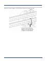
The omni-directional scanning capabilities of the Dolphin 7200 2D terminal greatly simplify operation and training and increase
productivity.
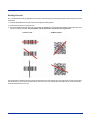
1. Press the ON/SCAN button to project the scanner's bright red aiming beam
2. Center the aiming beam over the barcode.
3. The red SCAN LED illuminates when the user presses the ON/KEY key and the green DECODE LED illuminates when a bar
code is successfully decoded. The aiming beam can be positioned in any direction for a good read.
Linear bar code
2D Matrix symbol
The aiming beam is smaller when the terminal is held closer to the code and larger when it is farther from the code. Symbologies
with smaller bars or elements (mil size) should be read closer to the unit. Symbologies with larger bars or elements (mil size)
should be read farther from the unit.
5-2
Dolphin® 7200 User’s Guide
Capturing Images
The image-capture process is a split-second operation for experienced users. By following the basic guidelines, new users can
easily develop their own technique and, with practice, quickly learn to adapt it to different circumstances.
The basic steps for acquiring images using the Dolphin 7200 2D terminal are:
1. To aim, hold the Dolphin terminal horizontally at a 45° angle approximately 2 to 9 inches (5 to 20 cm) away from the target.
You may have to adjust the angle at which you hold the Dolphin if there is glare on the screen.
2. Press the ON/SCAN button to take an image. Use the live video image on the terminal screen as a guide for positioning and
aiming the terminal at the target. You may find it helpful to start by moving the terminal further away and then in closer to the
target. The active screen image will have a slightly degraded appearance compared to the captured image. This is normal.
3. Release the ON/SCAN button to capture the image when the desired image is displayed on the terminal screen. Hold the
Dolphin terminal as still as possible when capturing the image.
Image Quality and File Size
The image quality and related file size is determined by the data compression method used by your software application. For
highest quality, take grayscale images. When saved, the image will be saved in JPEG file format. The size of the file depends
on the information content of the image and will be approximately 4-8 K.
Lighting Conditions
The Dolphin 7200 2D terminal is designed to read bar codes and take images in dim light conditions. It is suggested that you turn
on the unit's electroluminescent display backlight when taking images in extreme low light conditions to help with aiming.
Dolphin 7200 2D Demo Software
The Dolphin 7200 2D terminal demonstration software allows you to show terminal's ability to do omni-directional decoding,
image capture and I.Q. Imaging.
The Image Capture demo requires that you have a PC available with a program such as the Dolphin File Transfer utility that is
capable of receiving files via Ymodem protocol, and a Dolphin home base connected to that PC.
For more information on using the Dolphin File Transfer Utility, see Transferring Files to or from the Dolphin Terminal on page 6-9.
Re-Installing the Dolphin 7200 Demo Applications
The Dolphin 7200 2D terminal is shipped loaded with the demonstration software. If the demo software has been removed from
your terminal, follow these steps to re-install it:
1. Download the demonstration installation programs from the Partners area of the web site: www.handheld.com. The program
is called DEMOS.EXE and is a self-extracting zip file that installs the Demo applications and also offers to replace the
Dolphin terminal's AUTOEXEC.BAT file.
2. Use the Dolphin File Transfer utility to load DEMOS.EXE onto the Dolphin unit.
3. Run DEMOS.EXE.
4. Start the demo program by typing DEMOSTART at the C:> prompt and then pressing ENTER.
If you chose to let DEMOS.EXE overwrite the AUTOEXEC.BAT, perform a three-key reset (pressing and releasing the
SHIFT, ON/SCAN and BKSP keys at the same time.) and the program will start.
Dolphin® 7200 User’s Guide
5-3
Dolphin Demo Main Screen
When you start the program, this menu screen will be the first one you see. This screen allows you to access the demonstration
programs listed or exit to DOS. All the Demo programs will return to this menu screen when exited.
F1-Decoding Demo
F2-Imaging Demo
F3-I.Q. Demo
F4-Exit to DOS
If there is no keyboard activity over a short period of time, press any key to go to the Dolphin Demo Main Screen.
F1 - Decoding Demo
Press F1 and the Scan a Target screen shown below will display:
Scan a Target
F3-Setup
H-Help
For optimal scanning performance for your application, the 2D imager has three scanning modes: standard omni, reduced omni
and Advanced Linear Decoding (ALD).
To scan a bar code:
1. Press and hold the ON/SCAN button.
2. You will see the scanner alternate between a thin green aiming line, and a general red flash. The flash is when the imager is
actually taking an image and attempting to decode any barcodes in the image.
3. After the Dolphin successfully decodes a barcode, the Decoded Message screen shown below will display.
UPC
C7771104501
The top of the screen tells the name of the symbology decoded, the bottom of the screen tells the
length of the data decoded, and the middle section shows the message. If the message is long, you
can scroll up and down using the F1 & F2 keys to read the data. To scan again, just press the ON/
SCAN button again.
3.
5-4
To exit demo, press F4 and you will return to the Dolphin Demo Screen.
Dolphin® 7200 User’s Guide
F2 - Imaging Demo
Press F2 and the screen shown below will display:
Press ON/SCAN to
capture an image
F3-Setup
H-Help
To setup the imager, press F3.
To Take an Image:
1. Press and hold the ON/SCAN button. Release the ON/SCAN button to capture the image when the desired image is
displayed on the terminal screen. When you release the ON/SCAN button, the terminal will save the image taken. You will
hear a confirming set of beeps and the screen shown below will display.
Set Dcomm to
receive a file
Place in Base
Press ENTER
2. Place the unit in the Home Base, start the Dolphin File Transfer utility on your PC and set it to receive a file.
3. Press ENTER on the Dolphin terminal to transfer the image to your PC. Go to the directory to the file was transferred and
you should see a file titled Gray.jpg.
4. Double click on the file to launch the viewer to see the image. Browsers like Internet Explorer are good tools for looking at jpg
images. (Note: If you changed any file format settings in the setup window for the program, the name of the file will be
different).
5. You can skip sending the file by pressing enter, then pressing esc when the Dolphin attempts to transmit the file. F4 on the
"Press ON/SCAN" screen will allow you to exit the application.
F3 - I.Q. Imaging Demo
Press F3 and the Scan the Test Target screen shown below will display:
Scan the Test Target
For this demo, you must use the test target shown below. See Appendix E for a copy of the test target to make copies for multiple
uses in the future.
Dolphin® 7200 User’s Guide
5-5
To use the demo:
1. Enter a signature in the box below.
2. Press and hold the ON/SCAN button and aim at the barcode. When the engine successfully decodes, you will hear a short
beep. The image engine will then take an image of the signature. When the signature is captured, the terminal will beep and
the screen shown below will appear on the screen.
Tracking Number:
231498324
Address:
Hand Held Products
7520 E. Independence Blvd.
Charlotte, NC 28227
3. The data shown is information contained in the barcode. Press the ENTER key and the signature captured screen will be
displayed as shown below:
Captured Image:
4. Press ENTER to return to the Scan the Test Target screen. Press F4 to exit the demo and return to the demo main menu.
5-6
Dolphin® 7200 User’s Guide
6
Dolphin OS and System Development Software
Important Notice: Only install the most recent release of the Dolphin ROM IMAGE and Bootloader, loading an old version of the
ROM IMAGE or Bootloader can result in Dolphin becoming unstable or inoperable, and requiring the unit to be returned to Hand
Held Products for repair.
The Dolphin OS and Development System is available from the Partners Area of the web site at www.handheld.com. The selfextracting file contains:
•
•
•
•
•
Dolphin Development Tools and Libraries (API)
Sample Programs with source code
Dolphin Utilities including Communication and Upgrade Wizard
Electronic Help
Bootloader & ROM Image
Installation
Once the file is downloaded on your PC, double click the Dolphin OS and Development System icon and follow the instructions
on the screen to complete the installation and set-up procedure.
Default Installation Directories
There are two install packages - one for the Dolphin 7200 2D and one for the Dolphin 7200 Batch and Laser configurations. Each
configuration has its own default directory:
c:\Dolph34\ is the default directory for the Dolphin 7200 2D.
c:\Dolph43\ is the default directory for the Dolphin 7200 Batch and Laser.
In the table below, this will be represented by c:\dolphXX\
Directory
Contents
c:\dolphXX\
Default installation directory, containing the Help and Read Me
First Files.
c:\dolphXX\bootldr
Backup of Dolphin Bootloader (BURN.EXE and BOOTLDR.BIN)
c:\dolphXX\devtools
Dolphin Development Libraries, Samples and API Help file.
c:\dolphXX\wizard
Dolphin Upgrade Wizard
c:\dolphXX\demo
Dolphin Batch Demo Program
c:\dolphXX\romimage
Backup of Dolphin ROM Image
c:\dolphXX\utils
Dolphin Utilities (YX.EXE, DCOMM2.EXE, BMP2LCD.EXE)
c:\dolphXX\devtools\samples\
Sample applications
Note: All future references to directories assume that the user has accepted the installation default directory.
Dolphin® 7200 User’s Guide
6-1
Help File, Document and Utility Icons
The Dolphin OS and Development System set up program will set up a Dolphin group or folder and install the following Help,
Document and Utility icons.
Icon
Tapping this icon, …
Provides important information not available at the time the manual was printed.
Provides information on contacting Hand Held Products by Phone, Fax, Email, WWW and BBS.
Provides additional information on the Dolphin OS and Development System.
Provides information on the Dolphin API and Sample applications.
Provides an Electronic User’s Guide for the Dolphin terminal.
A Windows drag-and-drop communication utility, supporting Xmodem and Ymodem file transfer protocols
A Windows utility that steps you through the process of upgrading Dolphin's Bootloader, ROM image and
Demo application.
A Windows utility for configuring the HomeBase baud rate.
6-2
Dolphin® 7200 User’s Guide
Dolphin Utilities
A number of utilities are provided with your Dolphin terminal. The Utility programs are installed in the c:\dolphXX\utils on
your computer.
Note: See the Development API electronic Help file (dolphapi.hlp) for additional information regarding the Dolphin Development
Libraries, samples and compiling instructions.
BMP2LCD.EXE
BMP2LCD.EXE is a Windows tool that allows developers to create a bitmap data structure from a standard Windows bitmap.
The bitmap can then be displayed using a Dolphin Developers API function such as evDrawUserBitMap().
BURN.EXE
BURN.EXE is a Dolphin utility that will load or reload the Dolphin's Bootloader. The Bootloader is an Xmodem communications
utility used by the Dolphin OS to load or update the BIOS and Operating System (ROM image).
!
Install only the most recent release of the Dolphin Boot Loader, loading an old version of the Boot loader can result in
Dolphin becoming inoperable, and requiring the unit to be returned to Hand Held Products for repair.
To Load or Reload the Dolphin's Bootloader:
1. Transfer BURN.EXE and BOOTLDR.BIN to the Dolphin's FLASH Drive C:
2. Execute BURN.EXE. The OS Bootloader is updated and the files BURN.EXE and BOOTLDR.BIN are deleted.
DCOMM2.EXE - Dolphin File Transfer Utility
DCOMM2.EXE is a Windows communication utility that supports drag-and-drop file transfer using both Ymodem and Xmodem.
Usage:
dcomm2 [/c#] [/b#] [/y] [/x] [filename1…n]
Where:
/c#
Specifies COM port, where #=1-4
/b#
Specifies Baud Rate, where #=9600, 19200, 38400 or 57600
/x
Specifies Xmodem protocol
/y
Specifies Ymodem protocol
/a
Automatic mode, waits and receives all files that are sent
filename
Filename to transfer, supports multiple file names and wildcards (*.dat).
Example:
Dcomm2 /c1 /b57600 /y filename.dat
Dolphin® 7200 User’s Guide
6-3
If you do not specify command line arguments, DCOMM2.EXE will open a dialog that allows you to receive files or configure the
default serial communications port, baud rate, communications protocol and download path.
An 'Auto Execute' command line can also be specified in the configuration screen. The specified command line will be executed
when a file is received.
DWIZARD.EXE (Dolphin Upgrade Wizard)
DWIZARD.EXE is a Windows utility that steps you through the process of upgrading Dolphin's Bootloader, ROM image and
Demo application. Simply run DWIZARD and follow the instructions provided to:
• Upgrade the terminal Bootloader
• Upgrade the terminal ROM Image (BIOS, A Drive Image)
• Reinstall/Upgrade the Demo Program
HBCFG.EXE - HomeBase Configuration Utility
HBCFG.EXE is a Windows utility that allows the user to change the baud rate setting for the Dolphin HomeBase. HBCFG.EXE
supports the following command line arguments:
Usage:
hbcfg [/c#] [/I] [/b#]
Where:
/c#:
Specifies COM port, where #=1-4
/b#:
Specifies Baud Rate, where #=9600, 19200, 38400 or 57600
6-4
Dolphin® 7200 User’s Guide
/I:
Forces HBCFG.EXE to display 'Please wait Dialog'
Example:
hbcfg /c1 /b57600 /I
If no command line arguments are specified or an error is detected, HBCFG.EXE will open a dialog that allows the user to select
the serial communications port, baud rate, or run a diagnostic.
Note: Dip Switch 2 located on the back of the HomeBase must be set in the Up (PROGRAM) position for the baud rate to be
programmed. The HomeBase power must be cycled (turned off and on) for the new dip switch settings to be recognized.
STL.EXE
STL.EXE is a DOS command line utility for Dolphin that turns the 9th line status indicators on or off.
Usage:
STL [1] [0]
Where:
1:
Turns the status line on
0:
turns the status line off
Example:
STL 1
If no command line is specified, STL.EXE will toggle the status line off, if it was on, and on if it was off.
YX.EXE
YX.EXE is a DOS command line Ymodem communication tool for the Dolphin terminal or a PC.
YX.EXE supports the following options:
Usage:
yx {/c#] [/b#] [/m] [filename]
Where:
filename:
refers to file name to send, if not specified YX will receive a file
/c#:
Specifies COM ports 1-4
(1=Ir Port, 2=Micro DB-9)
/b#:
Specifies new BAUD rate, 300-57600
/m:
Run YX in menu driven mode
Examples:
yx /b57600 autoexec.bat
yx
Dolphin® 7200 User’s Guide
6-5
yx /m
yx /c2
The default baud rate for the YX.EXE utility is 9600. For your convenience, batch files are included on the Dolphin terminal to
make sending data at a higher baud rate easier.
Note: When using YX on the Dolphin 7200 terminal, only COM1 is available.
To send at 38400, enter YF instead of YX/b38400.
To send at 57600, enter YFF instead of YX/b57600.
For more information, see Using the YX.EXE Utility on page 6-9.
ZZZ.EXE
ZZZ.EXE is a DOS command line utility for Dolphin that places the terminal into sleep mode.
Note: The terminal can not be placed in sleep mode while it is in the HomeBase. While in a HomeBase, the terminal must be
on so it can monitor the battery status.
ROM Image
The following Utilities are included in the Dolphin ROM image and are automatically loaded when the terminal boots. They are
NOT included on the Dolphin OS and Development System Disk.
Utility
Description
EVS.EXE
Enhanced Video System (EVS) is a TSR that traps standard video BIOS (INT 10H) calls,
and overlays hardware-specific support for the Dolphin's LCD. In addition, EVS provides
application and system level Status line support.
POWERMON.EXE
POWERMON.EXE is a TSR that monitors battery status and power usage and is loaded
when the terminal boots.
6-6
Dolphin® 7200 User’s Guide
Dolphin Application Development
Dolphin application development is straightforward. Since Dolphin is DOS-compatible, most of the application can be tested on
a desktop computer.
Compiling Applications for the Dolphin
Although the operating system on the Dolphin 7200 is DOS-compatible, it provides many unique features that are not built into
most PCs. For example, it has an integrated bar code scanner. The Dolphin libraries provide an API that allows an application
to use these features.
There are four libraries provided for linking into applications:
dolphins.lib
for small memory models
dolphinm.lib
for medium memory models
dolphinc.lib
for compact memory models
dolphinl.lib
for large memory models
The header file, dolphin.h, in the c:\dolphXX\devtools\ directory contains useful declarations for using these
libraries.
Sample Applications
A number of sample programs with source code have been provided with your Dolphin terminal. The sample programs are
installed in the c:\dolphXX\devtools\samples directory on your desktop computer.
Application
Description
GRAPH
Draws various patterns on the Dolphin's LCD display.
KBSTATUS
Displays keystrokes. If the keystroke is non-printable, the hex value of the keystroke is
displayed.
LED
Allows the red and green LEDs to be toggled
ONBHIT
Displays status of the ON key.
SCAN
Allows bar code scanning.
SIO
Performs serial I/O. Displays characters received and sends key strokes.
SOUND
Runs through the frequency range of the Dolphin's speaker.
NI
Sample programs for the Numeric Dolphin. This sample is located in the
C:\DOLPHIN\DEVTOOLS\NUMERIC\BORLAND or
C:\DOLPHIN\DEVTOOLS\NUMERIC\MSVC.
EVSDEMO
Demonstrates graphics, changing fonts, turning the status line on and off, adding new
icons to the status line, and changing the system cursor.
INV5
Sample inventory application with source code.
Dolphin® 7200 User’s Guide
6-7
Building the Samples
There is one Microsoft Visual C\C++ version 1.52 project file (*.mak) for each sample application. There is also a Borland C++
version 5.0 project file, samples.ide. This project file will rebuild all sample applications. Consult the documentation for your
compiler for information on the use of project files.
Compiling the Sample Programs
Note: See the Development API Help file (DAPI.HLP) for complete information regarding the Dolphin Development Libraries,
Samples and Compiling instructions.
Microsoft
In order for an application to use Dolphin's unique features, you must add a Dolphin library to the application's project. There are
four libraries located in c:\dolphXX\lib\msvc named dolphinx.lib where x is s, m, c, or l, corresponding to the memory
model.
To Add dolphinx.lib to an Application's Project:
1. Select the menus Project > Edit.
2. Change List Files of Type: to Library (*.lib). Browse into c:\dolphXX\devtools\lib\msvc. Select dolphinx.lib
corresponding to the memory model.
3. Click the Add button.
4. The Include Files Path must be modified, so the compiler will search for include files in
c:\dolphXX\devtools\include.
Borland
For an application to use Dolphin's unique features, you must add a Dolphin library must be added to the application's project.
There are five libraries are located in c:\dolphXX\devtools\lib\Borland directory. They are named dolphinx.lib
where x is t, s, m, c, or l, corresponding to the memory model.
To Add dolphinx.lib to an Application's Project:
1. Right click on the .exe file in the Project Window.
2. Select Add node from the pop-up menu.
3. When the Add to Project List dialog box is displayed, change Files to Type: to Libraries (*.lib).
4. Browse to c:\dolphXX\devtools\lib\borland.
5. Select the dolphinx.lib library corresponding to the memory model. Click the Open button.
6. The Include Files Path must be modified, so the compiler will search for include files in
c:\dolphXX\devtools\include.
6-8
Dolphin® 7200 User’s Guide
Transferring Files to or from the Dolphin Terminal
Transferring files between your Dolphin terminal and a desktop PC is easy with the YX.EXE utility (see YX.EXE on page 6-5) or
the Dolphin File Transfer program (see DCOMM2.EXE - Dolphin File Transfer Utility on page 6-3).
Using the YX.EXE Utility
The YX.EXE utility, installed in the directory c:\dolphXX\utils, performs RS-232 file transfers using Ymodem batch
protocol. In addition, YX.EXE is pre-loaded on the Dolphin's A drive. This program can be run by entering commands at the DOS
prompt or by accessing a menu.
Note: When using YX on the Dolphin 7200 terminal, only COM1 is available.
For a sample, see YX.EXE on page 6-5.
Using the Dolphin File Transfer Program
Open the Dolphin program group in Windows Explorer and copy the Dolphin File Transfer shortcut to your PC's desktop. Putting
the shortcut on your desktop simplifies the file transfer process.
Sending a File to the Dolphin
1. Open the Dolphin File Transfer Program Configuration dialog box. Check to make sure the baud rate is set at 57600. This is
the default for YX.EXE. Close the Configuration dialog box and exit the Dolphin File Transfer program. To change the baud
rate, see Sending Files at a Higher Rate on page 6-9.
2. Open Windows Explorer. Resize and move the window so that you can see both Explorer and the Dolphin File Transfer
shortcut on your desktop.
3. In Windows Explorer, select the file to be transferred and, while holding down the left mouse button, drag and drop the file on
the Dolphin File Transfer shortcut on the desktop. This opens the Dolphin File Transfer program.
4. At the Dolphin's C: prompt, enter YX.
5. Press ENTER on the Dolphin terminal to begin the file transfer.
6. The COMM LED on the Dolphin HomeBase will blink red and green during the transfer. You can also view the progress of
the file transfer on the Dolphin screen and Dolphin File Transfer program window.
Sending a File From Dolphin to Your PC
1. Double-click on the Dolphin File Transfer shortcut to open the program.
2. Open the Configuration dialog box. Check to make ensure the baud rate is set at 57600.
3. At the Dolphin's C: prompt, enter YX [Filename].
4. Click on the Receive File button.
5. Press ENTER on the Dolphin terminal to begin the file transfer.
6. The COMM LED on the Dolphin HomeBase will blink red and green during the transfer. You can also view the progress of
the file transfer on the Dolphin screen and in the Dolphin File Transfer program window.
Sending Files at a Higher Rate
A batch file containing command lines for sending and receiving files at higher baud rates is also loaded on the Dolphin terminal.
To send at a higher rate, the Dolphin HomeBase must be programmed at the higher baud rate. Configuration Switch 2 should
be in the down position.
• To send at 38400 baud rate, enter YF at the DOS prompt instead of YX.
• To send at 57600 baud rate, enter YFF at the DOS prompt.
Note: When using the menu, press F3 to change to a higher baud rate. If you are using a HomeBase to transfer files, be sure
to set Configuration Switch 2 on the HomeBase in the up position.
Dolphin® 7200 User’s Guide
6-9
Using the Dolphin File Transfer Program and YX in Menu Mode
You can also use YX in menu mode to send and receive files from the Dolphin to your PC and vice versa with the Dolphin File
Transfer program and YX.EXE on the PC.
Sending Files to the Dolphin
To use a menu for sending files to the Dolphin, follow these steps:
1. Open the Configuration dialog box.
2. Check to make sure the baud rate is set at 57600. This is the default for YX.EXE.
3. Enter YX /M at the Dolphin terminal's DOS prompt.
4. Press ENTER and the menu below will appear on your Dolphin terminal's screen:
Port=1
Baud Rate=9600
F1=Send File
F2=Receive File
F3=Set Baud Rate
F4=Choose Port
Q=Quit
5. In Windows Explorer, select the file to be transferred and, while holding down the left mouse button, drag and drop the file on
the Dolphin File Transfer shortcut on the desktop. This opens the Dolphin File Transfer program.
6. Press F2 to begin the file transfer.
If you are using a HomeBase to transfer files, the COMM LED will blink red and green during the transfer. You can also view
the progress of the file transfer on the Dolphin screen and status bar in the Dolphin File Transfer program window.
Sending Files from the Dolphin to Your PC
1. Double-click on the Dolphin File Transfer shortcut to open the program.
2. Open the Configuration dialog box. Check to make sure the baud rate is set at 57600.
3. Enter YX/M at the Dolphin terminal's DOS prompt.
4. Press ENTER and the menu below will appear on your Dolphin terminal's screen:
5. Click on the Receive File button.
6. Press F1 on your Dolphin terminal and then enter the name of the file. Press ENTER.
7. If you are using a HomeBase to transfer files, the COMM LED on the Dolphin HomeBase will blink red and green during the
transfer. You can also view the progress of the file transfer on the Dolphin screen and status bar in the Dolphin File Transfer
program window.
6 - 10
Dolphin® 7200 User’s Guide
Dolphin EVS Engine
The EVS engine provides bit-mapped graphics support for the Dolphin LCD. EVS is the primary interface between an application
and BIOS graphics functions.
The EVS engine eliminates the need for an application to directly access the hardware layer. The EVS engine maintains an image
of the display in memory (118 pixels wide by 73 pixels tall). All application screen access (read/write) is filtered so as to write to
the display image rather to the hardware. The EVS engine then updates the hardware (e.g. writes to the display) as necessary.
This process allows for support of a single display plane that combines graphics and text.
The EVS engine consists of three basic parts:
1. A TSR (EVS.EXE) that traps standard video BIOS (INT 10H) calls, and overlays hardware specific support for the Dolphin
LCD.
2. A set of API routines that allow easy access to the EVS specific routines. These functions have been merged into the
standard Dolphin Development API and are documented in the Dolphin API Help file (DAPI.HLP).
3. Application and system level Status line support.
For more on the Dolphin EVS Engine, see the Dolphin OS and Development System electronic help file.
Dolphin ROM Image and Bootloader
Important Notice: Before installing the Dolphin OS and Development System, you must remove all previous installations. To do
this, delete the C:\DOLPHIN directory and all files contained within as well as the Dolphin Group or Folder. Only install the most
recent release of the Dolphin ROM IMAGE and Bootloader. Loading an old version of the ROM IMAGE or Bootloader can make
the Dolphin unstable or inoperable, and requiring you to return the unit to Hand Held Products for repair.
Upgrading the Dolphin ROM Image
The Dolphin terminal has a Bootloader incorporated that allows the developer to upgrade or reload the ROM IMAGE.
Follow these steps to manually reload the ROM IMAGE and Operating System from DOS:
1. Verify that Configuration Switch 2 on the back of the Dolphin HomeBase is set to "Fixed BPS" and Switch 1 is set to "Single".
Power must be turned off and then on to accept the new dip switch settings.
2. Make sure the serial cable is properly installed and power is properly connected to the HomeBase. Make sure no other
communications programs are running on the PC.
3. Start the Dolphin Bootloader. Hold down the 7 and 9 keys with one hand. With your other hand, press and release the ON/
SCAN, SHIFT and BKSP keys. Release the 7 and 9 keys. You should see the screen below. If not, repeat Step 3.
SYS Utilities X.XX
1 Download
2 Launch Bios
3 Set Baud Rate
Baud: 57600
Dolphin® 7200 User’s Guide
6 - 11
4. Press 3 to select Baud rate. Press 1 to set baud rate to 57600.
SYS Utilities X.XX
1
2
3
4
9600
19200
38400
57600
Baud: 9600
5. Press 1 to download.
Upgrading the Dolphin Bootloader
!
Install only the most recent release of the Dolphin ROM IMAGE and Boot Loader. DO NOT load an old version of the
ROM IMAGE or Bootloader. The Dolphin may become unstable or inoperable requiring you to return the unit to Hand
Held Products for repair.
Hand Held Products recommends that you use the Dolphin Upgrade WIZARD to update the Dolphin Boot Loader, ROM image
and Demo Programs. Simply run DWIZARD and follow the instructions provided.
While it is unlikely that you will ever need to reload the Dolphin Boot Loader, an image of the Dolphin Boot Loader is included
with the Dolphin OS and Development System just in case. The Boot Loader image is installed in the c:\dolphXX\BOOTLDR
directory on your PC.
To Load or Reload Dolphin's Boot Loader:
1. Transfer BURN.EXE and BOOTLDR.BIN to Dolphin's FLASH Drive C:\.
2. Execute BURN.EXE. The OS Boot Loader is updated and the files BURN.EXE and BOOTLDR.BIN are deleted.
6 - 12
Dolphin® 7200 User’s Guide
7
Troubleshooting
Dolphin Terminal and HomeBase
This table describes some of the common problems/symptoms and solutions that you could encounter while using your Dolphin
terminal or Dolphin HomeBase. If you need further assistance with troubleshooting your terminal, contact your Hand Held
Products Authorized Reseller.
Troubleshooting the Dolphin Terminal and HomeBase
If You Have This Problem/Symptom
Try This:
The display is blank, the Dolphin
terminal will not turn on.
Is the battery is low? Recharge or replace it with a known good battery. Reset
the Dolphin terminal.
When booting up the Dolphin, I see
the message CMOS MEM size
wrong for a second or two and the
unit continues to boot. Is there
something wrong with my unit?
When the Dolphin's internal NiMH battery is not charged or run down, this
message will display and the terminal's settings are reset to their default
values. This includes the date and time which is reset to January 1, 1980 and
12:00 AM. The terminal is fine. You simply need to recharge the internal
battery and reset the Dolphin's date and time. To do this, insert a fully charged
battery in the Dolphin and then use the DOS Date and Time function to set
the correct date and time. The internal back-up battery requires a minimum of
5 hours of charging time in order to perform and maintain the system. For
more information about battery maintenance, Maintaining the Dolphin's
Batteries (page 3-8).
The Dolphin terminal will not scan a
bar code.
The bar code may be out of spec. Try reading some of the bar code examples
in Appendix C, or locate a bar code sample that you know can be read by
another Dolphin terminal.
Is the exit window dirty? Clean it with a soft dry cloth. If the exit window is
badly scratched, the Dolphin terminal should be returned to Hand Held
Products for repair.
Consult your software developer to ensure the correct bar code symbology is
being used.
The battery in the Dolphin terminal
keeps failing.
If the battery has been stored for a long period of time, it may take three
charge/discharge cycles before the battery reaches its full storage capacity.
The capacity of NiMH batteries decreases as the number of charge/discharge
cycles increases. So, if you are experiencing low run times, a new battery may
be required.
To increase the run time of the Dolphin terminal, try to limit the use of the
speaker, scan engine and backlight.
The Dolphin terminal is not
communicating with the host
computer.
Make sure the HomeBase is connected to a power source.
Make sure the Dolphin terminal is inserted properly into the HomeBase. The
CHARGING MAINBATT LED should be solid green. If not, remove the
Dolphin terminal and reinsert it into the HomeBase.
Ensure the communications baud rate is set correctly. Set communications for
57600, N, 8, 1. Make sure that Configuration Switch 2 on the back of the
HomeBase is set to Fixed BPS.
Make sure the RS-232 cable is properly attached to the HomeBase and host
computer. Also, check to ensure that the cable is configured properly.
Dolphin® 7200 User’s Guide
7-1
Troubleshooting the Dolphin Terminal and HomeBase
If You Have This Problem/Symptom
Try This:
I can not enter a ":" to change to Drive
B: at the DOS prompt.
The ":" is a special character that can be entered by typing "SHIFT" "Z". See
reference to special characters in Using the Alphanumeric Keypad (page 3-2)
or Using the Numeric Keypad (page 3-4).
The CHARGING AUXBATT LED does
not come on when I insert a battery
pack into the Dolphin HomeBase.
Check the power connections on the Dolphin HomeBase. Also check to
ensure the battery pack is properly seated.
The CHARGING AUXBATT LED
constantly changes from RED to
ORANGE to GREEN.
The NiMH battery pack may need to be replaced. Insert a new battery pack
into the Dolphin HomeBase's auxiliary battery well.
The CHARGING MAIN BATT LED is
on, but the Dolphin terminal will not
communicate.
Check the cable connections to other devices. If you are connecting to
another DCE device, be sure you're using a null modem cable. Try a
previously tested cable if you suspect a bad cable.
Check your communications program in both the Dolphin terminal and the
RS-232 device with which you are communicating. Verify that the baud rates
are set properly.
Troubleshooting with Dolphin 7200-2D
Image is not readable …
Try This:
Because it is too dark
Move to an area with more light to take image.
Because it is distorted
Hold Dolphin with Image-Capture terminal at 90 degree angle.
Because it is cut off
You are holding terminal too close to subject. Hold the terminal at a 90 degree
angle and move it further away from the subject.
Because of a dirty lens
Wipe lens with clean, lint free cloth.
Because it is too small.
You are holding the terminal too far away from the subject. Hold the terminal at
a 90 degree angle and move it closer to the subject.
Due to reflection
Adjust the angle at which you are holding the Dolphin terminal to avoid a
reflection.
7-2
Dolphin® 7200 User’s Guide
8
Dolphin HomeBase
Hub of the System
As the hub of your Dolphin system, the Dolphin 7200 HomeBase performs three important functions - battery management,
communications and storage.
Battery Management
The Dolphin 7200 HomeBase uses a charging method that senses when the battery pack is fully charged and then drops to a
trickle charge to keep the battery pack at full capacity. The battery pack does not need to be discharged before recharging
because this method protects the battery from damage caused by overcharging.
IrDA Optical Communications
The IR communications port on the HomeBase connects with the IrDA port on the Dolphin. Reliable data communications at
speeds of up to 115K baud can be transmitted by the HomeBase. With no pins or contacts to break, IrDA will work reliably for
years.
The Dolphin 7200 HomeBase can be networked together for mass programming and charging. Units are individually
addressable, allowing each HomeBase to be automatically loaded with the right information and files for its user.
Convenient Storage
The Dolphin 7200 HomeBase is a safe and convenient storage receptacle for the Dolphin terminal. The HomeBase also holds a
spare charged battery pack.
Dolphin® 7200 User’s Guide
8-1
Dolphin 7200 HomeBase Parts and Functions
Front Panel
Dolphin Terminal Well
Multi-Serial Port
Main Serial Port
Charging Main
Battery LED
COMM
LED
Charging Aux
Battery LED
Dolphin Terminal Well
You put the Dolphin in this well to communicate with a host device and to charge the Dolphin's
batteries.
LEDs
There are three LEDs that you can use to monitor the status of battery charging and communications
status:
1. Charging Main Batt
Turns solid green when the Dolphin terminal is properly seated into the Dolphin HomeBase. The
Charging Main Batt LED does not indicate the battery status of the Dolphin terminal.
2. COMM
Indicates the status of data transfer between the Host Device and the Dolphin terminal as described
below:
3. Charging Aux Batt
Comm LED
Description
Red LED
Data is being sent from the Host Device to the Dolphin HomeBase.
Green LED
Data is being sent from the Dolphin HomeBase to the Host Device.
Orange LED
Data is being sent at high data rates.
Indicates the status of the auxiliary battery pack in the Dolphin HomeBase as described in the table
below:
Charging Aux Batt LED Description
8-2
OFF
Battery pack not properly inserted into the auxiliary battery well, or
the HomeBase has no power
Red
Battery discharging
Blinking red LED
Charge cycle initializing
Dolphin® 7200 User’s Guide
Charging Aux Batt LED Description
Blinking orange LED
Battery charging at the maximum rate
Solid green LED
Trickle charging; battery pack is ready for use
Back Panel
Auxiliary Battery Well (without battery inserted)
Configuration
Switches
Auxiliary Battery Well
Service Aux
Battery Switch
Power Supply
Connector
Insert a battery into the well to charge a second battery and you will always have a spare. The
auxiliary battery well can also service your battery pack.
Configuration Switches Use these switches to select the network and communications modes for your Dolphin. See Chapter
8 for more on the configuration switch settings. The configuration switches are checked at power up.
Changes in the switch settings will not be recognized until power is turned off and then back on
Service Aux Batt Switch Press and hold this button for four seconds to service the battery in the auxiliary battery well. For
maximum battery life, the battery should be serviced, or calibrated once a month. The Charging AUX
BATT LED is red while the battery is discharging and changes to blinking red when the charging cycle
begins. The battery is ready to use when the light turns green.
Power Supply Connector Use this connector to attach a power supply to the HomeBase. The power supply provides 12V DC
input for communications and battery charging.
Dolphin® 7200 User’s Guide
8-3
Side Panels
There is a main communications port on one side and a multi-HomeBase-port on the other side:
Main Communications Port
Use a standard serial cable to connect this port to a host RS-232 device if the Dolphin HomeBase is the first unit of HomeBase
network. Otherwise, the main communications port connects to another Dolphin HomeBase Multi-HomeBase Port to form a
daisy-chained network; see Configuration Switch Settings for a HomeBase Network on page 8-10.
Multi-HomeBase Port
Use this port to form a Dolphin HomeBase Network. This port mates with the next HomeBase's main communications port to
form an addressable network.
Note: The Multi-HomeBase Port cannot be used for communications to standard serial devices.
8-4
Dolphin® 7200 User’s Guide
Charging Batteries in the Dolphin 7200 HomeBase
!
Use only the 3.6V battery packs provided by Hand Held Products. The use of any other battery pack in the Dolphin
terminal will void your warranty and may result in damage to the Dolphin terminal or battery.
With the Dolphin HomeBase, you can charge a Dolphin terminal and a spare NiMH battery pack simultaneously. The HomeBase
charges the terminal and the spare battery pack independently.
When you insert a battery into the Dolphin HomeBase, it charges the battery at the highest rate possible. The HomeBase uses
a charging method that senses when the battery pack is fully charged and then drops to a trickle charge to keep the battery pack
at full capacity. You do not need to discharge the battery pack before recharging because this method protects the battery from
damage caused by overcharging. A dead battery will charge to full capacity in approximately three hours.
The Dolphin terminal can be stored indefinitely in the HomeBase without damage to the terminal, battery packs, or the
HomeBase. Keep the HomeBase plugged in so that the battery pack in the Dolphin terminal stays fully charged.
Charging a Dolphin Terminal
1. Insert a battery pack into the Dolphin terminal.
2. Place the terminal, laser engine window up and the LCD visible, in the Dolphin terminal well of the Dolphin HomeBase.
3. Let it glide down into the well until it stops.
4. Once the Dolphin terminal is properly seated, the Charging Main Batt LED on the HomeBase will be solid green.
DECO
SCAN
DE
D O L P H I N
SINGLE-HANDED
LASER
POCKET-SIZE
SCANNER
INFRA
DOS
POWER
PLATFORM
REDMGMT
COMM
F1
ON
SCAN
F3
ENTER
BKSP
F2
F4
ESC
SHIFT
CLR
A
F
K
P
7
4
1
=
B
G
L
Q
8
5
2
0
C
H
M
R
9
6
3
.
D
I
N
S
E
+
-
J
O
T
SPC
U
NUM
LOCK
CHARGING
MAINBATT
Dolphin® 7200 User’s Guide
V
W
Z
COMM
X
Y
LIGHT
CHARGING
AUXBATT
8-5
Charging an Additional NiMH Battery Pack
1. Insert an NiMH battery pack with the battery contacts pointing upward into the Dolphin HomeBase auxiliary battery well.
Battery contacts on
the HomeBase
After the battery is inserted into the auxiliary battery well of the Dolphin HomeBase you can use the CHARGING AUXBATT LED
to monitor the charging progress.
Deep-Cycling the Battery
For maximum battery life, Hand Held Products recommends that you deep- cycle (service) the battery twice before initial use and
then, once a month thereafter. To deep-cycle, insert the battery into the HomeBase auxiliary battery well. Then, push and hold
the Service Aux Batt button for at least 4 seconds. The deep-cycling process takes approximately 6.5 hours.
The CHARGING AUXBATT LED is red while the battery is discharging and changes to blinking red when the charging cycle
begins and orange when charging at the maximum rate. The battery is ready to use when the light turns green.
Communications
The Dolphin terminal and Dolphin HomeBase support RS-232 communications through the RS-232 Main Communications Port
(page 8-4) located on the side of the Dolphin 7200 HomeBase. This port translates the RS-232 signals from the host computer
into infrared signals to communicate with the Dolphin terminal.
The HomeBase RS-232 interface allows the Dolphin terminal to communicate to a personal computer, modem, or any standard
RS-232 device using a standard serial cable and communications software.
1. Setup the Dolphin HomeBase (see Setting up the Dolphin HomeBase on page 8-7).
2. Insert the Dolphin terminal.
3. Follow the data transfer sequence as described by your application.
8-6
Dolphin® 7200 User’s Guide
Setting up the Dolphin HomeBase
Set the Dolphin HomeBase on any dry, stable surface such as a desktop. Before mounting the Dolphin HomeBase, check to
ensure that all AC wall transformers have a nearby electrical outlet. Be sure to provide enough workspace with good lighting for
the user to view and operate the Dolphin terminal while it is in the HomeBase. Setting up the HomeBase involves three steps:
1. Connecting the cables
2. Setting the configuration switches
3. Setting the baud rate
Connecting the Cables
Connect the HomeBase to the host computer or other device by plugging an RS-232 serial cable into the RS-232
Communications Port on the rear of the HomeBase. The wiring of your cable depends on whether the other device is set up as
a DCE (Data Communications Equipment) or DTE (Data Terminal Equipment) device.
The HomeBase RS-232 Port is configured as a DCE device. To communicate with a DTE device such as a computer, use a
standard (or straight-through) RS-232 cable. To communicate with a DCE device, use either a null modem adapter in line with a
standard RS-232 cable, or a null-modem serial cable.
You can make your own cables by following the pin configuration in the chart below. To do so, you must determine if your host
RS-232 device is 9-pin or 25-pin, and whether it is configured as a DCE or DTE device.
HomeBase /Host
Port (DCE)
IBM AT DB9
(DTE)
IBM XT
DB25 (DTE)
Modem
DB25 (DCE)
2 (RD)
2
3
2
3 (TD)
3
2
3
5 (SG)
5
7
7
4 (DTR)
4
20
6
6 (DSR)
6
6
20
7 (RTS)
7
4
5
8 (CTS)
8
5
4
With the Dolphin 7200 HomeBase, use the appropriate cable to connect each device to the Main Comm Port for a single Dolphin
HomeBase or to the Multi-HomeBase Port if you are creating a Dolphin HomeBase network.
Connect the power supply to the Dolphin HomeBase. Plug the AC transformer into the Dolphin HomeBase 12 Volt DC power
supply connector. The AC wall transformer provided can power only one Dolphin HomeBase.
Note: Hand Held Products recommends that you leave the Dolphin HomeBase connected to its power source at all times, so
that it is always ready to use.
Setting the Configuration Switches
Use these switches to select the network and communications modes for your Dolphin HomeBase. If you are configuring the
HomeBase for a single Dolphin terminal, the switch must be in the 'Single' position for proper basic operation. The switch must
be set to 'Multi' for proper network operation if you are creating a HomeBase network. The configuration switch must be in the
program position to change the baud rate.
Dolphin® 7200 User’s Guide
8-7
Setting the Baud Rate
You may use the HomeBase Configuration utility program to select the baud rate. The program can also be used to change the
host system's COM port and will run a diagnostic check for optimal communications. After changing the baud rate, you must
power the HomeBase off and then on again. The program is one of the utility programs that come with the Dolphin OS and
Development System. For more on HomeBase Configuration, see the chapter 9.
Modes of Operation
Through the Command Mode, the host application software provides command instructions for configuring a single Dolphin
HomeBase or a network of HomeBases for communications. Once configured, the HomeBase(s) is in Transparent Mode and
ready for communications.
Command Mode
You can configure a single Dolphin HomeBase or a whole network and select units for communications via the host application
by entering the Command Mode. Data transmission is not possible while the Dolphin HomeBase network is in this mode.
Go into Command Mode by entering an escape sequence that informs the HomeBase network that it will be receiving commands
from the host device or application.
The escape string is:
<ESC>HHP
[>100ms<1s] Next Command
where ESC is an ASCII 27 character.
The escape string should be followed by a >100ms<1second period of line silence. When sending commands, the escape string
must precede the command string. The HomeBase automatically exits Command Mode after receiving each command.
Programming commands used for configuring single Dolphin HomeBases include Version Number and Baud Rate Selection.
You configure HomeBase networks using the Baud Rate Selection, Address Assignment and Device Selection programming
commands.
Transparent Mode
When the Dolphin HomeBase is selected by the host application and ready for communications, it is in Transparent Mode. In this
mode, the HomeBase facilitates point-to-point communication between the host device and the Dolphin terminal. Data sent
through the RS-232 link is passed directly to and from the Dolphin terminal via the Infrared Link between the terminal and the
HomeBase.
Configuring a Single Dolphin 7200 HomeBase
To prepare a single Dolphin HomeBase for communications, you must enter the Command Mode to configure the version
number and select the baud rate.
Version Number
To retrieve the version number for the Dolphin HomeBase:
1. Enter or send the escape and command strings:
<ESC>HHP
>100ms< 1s V
This command will return the version number but is not needed for communications.
Baud Rate Selection
The Dolphin HomeBase baud rate is set to 57600 at the factory. Use the configuration switches on the HomeBase's back panel
to select the network and communications modes for your Dolphin.
Note: The configuration switches are checked at power up. Changes in the switch settings will not be recognized until power is
turned off and then back on.
The baud rate is stored in Non-Volatile Memory and is retained even if the power is removed from the network.
8-8
Dolphin® 7200 User’s Guide
The following table outlines the configuration switch settings:
Switch
Setting
Function
1
SINGLE (UP)
Single HomeBase only
2
FIXED BPS (DOWN)
Baud rate fixed at 9600
2
PROGRAM (UP)
Baud rate can be programmed
To ensure communications, leave Switch 2 in the FIXED BPS position and configure your communications software for 9600
baud.
When Switch 2 is in the PROGRAM position, the baud rate can be changed by entering or sending the escape and command
strings:
<ESC>HHP >100ms< 1s Bn
where n is the ASCII number corresponding to the baud rate shown in the table below.
Baud Rate per Value of n
ASCII Value of “n”
Selected Baud Rate
ASCII Value of “n”
Selected Baud Rate
0
38400
6
19200
1
38400
7
38400
2
1200
8
57600
3
2400
9
115200
5
9600
For example, the string <ESC>HHPB6 (which consists of the escape string and the command B6) would set the baud rate for
the network to 19200. No response will be transmitted back to the host after executing this function.
Note: You can also the HomeBase Configuration Utility program to alter the baud rate.
Creating a Dolphin 7200 HomeBase Network
This information applies only to the Dolphin 7200 HomeBase. The Dolphin 7200 Compact HomeBase is not networkable.
Each HomeBase must have its own AC power adapter connected to a standard AC electrical socket. The group can be placed
on a table or desk, or rail-mounted using the mounting holes on the two outside Dolphin HomeBase units.
How to Daisy Chain the Dolphin HomeBases
To form a HomeBase network, daisy chain the HomeBases together using one of the following methods:
• Align adjacent units so that the MULTI-HOMEBASE PORT of one unit will mate with the MAIN COMM PORT of the next unit
until all HomeBases in the network are connected.
• Use a RS-232 cable to connect the Multi-HomeBase Port on one terminal to the MAIN COMM PORT on the next terminal.
Repeat this step to include each additional terminal in the chain. Connect the last terminal to the host computer and leave the
last MULTI-HOMEBASE PORT open if it is not needed.
Programming Commands
To configure a Dolphin HomeBase network, these attributes must be programmed:
1. Address Assignment,
Dolphin® 7200 User’s Guide
8-9
2. Baud Rate Selection, and
3. Device Selection.
Address Assignment
Use the Address Assignment command to establish unit IDs for each Dolphin HomeBase in your network. This must be done
before a unit can be selected for communications.
To establish an Address Assignment:
1. Type or send the escape and command strings to setup the configuration mode and establish the beginning unit ID number:
<ESC>HHP >100 ms< C >100 ms< 1s In
where n is the number representing the first unit in the network
For example, the string <ESC>HHPCI0 would instruct the network to set up ID numbers for all the units in the network
beginning at zero (0).
2. The first Dolphin HomeBase in the network receiving the command responds to the host with:
<SYN>
where <SYN> indicates that the command was accepted
3. In sequence, each Dolphin HomeBase will determine its own ID number by adding one to the previous ID number.
4. When ID numbers are established for all HomeBases, the last HomeBase will return this response to the host:
<ACK>n
where <ACK> indicates completion of ID configuration; n represents the ID number for the last unit in the network.
Programmer's Note: When sending ID numbers to the Dolphin HomeBase, remember that numbers typed on the keyboard are
ASCII numbers which will be converted to Hex when sent to the Dolphin HomeBase. For example, typing the command from the
keyboard:
<ESC>HHP >100ms< C >100ms< 1s I1
would instruct the network to set up ID numbers for each Dolphin HomeBase starting with the ASCII number 1. The first unit in
the network would actually receive the number 31 Hex (since ASCII 1 is equal to 31 Hex) as the starting ID number. Each unit
in the network would sequentially add one to this starting ID number to establish its own ID. So, for a network of 15 units, the final
ID number would be set up as 3F Hex. When the final unit sends back an <ACK>3F, the host computer (which converts Hex data
back to ASCII) will then display the ID number as "?" instead of 15 as you might expect.
Baud Rate Selection
The Dolphin HomeBase baud rate is preset to 57600 at the factory. Use the configuration switches on the back panel of the
HomeBase to select the network and communications modes for your Dolphin. The following table outlines the configuration
switch settings:
Configuration Switch Settings for a HomeBase Network
Switch
Setting
Function
2
FIXED BPS (DOWN)
Baud rate fixed at 9600
2
FIXED BPS (DOWN)
Baud rate fixed at 9600
When Switch 2 is in the 'PROGRAM' position, the baud rate can be changed using the following procedure or by using the
HomeBase Configuration Utility.
Enter or send the escape and command strings:
<ESC>HHP >100ms< 1s Bn
8 - 10
Dolphin® 7200 User’s Guide
n is the ASCII number corresponding to the baud rate shown in the table below. For example, the string <ESC>HHPB6 (which
consists of the escape string and the command B6) would set the baud rate for the network to 19200. No response will be
transmitted back to the host after executing this function.
Baud Rate per Value of n
ASCII Value of “n”
Selected Baud Rate
ASCII Value of “n”
Selected Baud Rate
0
38400
6
19200
1
38400
7
38400
2
1200
8
57600
3
2400
9
115200
5
9600
Device Selection
Use this command to enable the host device to select a specific Dolphin HomeBase in the network for communication.
1. Enter or send the escape and command strings:
<ESC>HHP >100ms< 1s Sn
where n is the unit ID of the Dolphin HomeBase being selected
2. The Dolphin HomeBase with the unit ID corresponding to the ID number in the Device Selection command string will
respond with:
<ACK>n
to indicate to the host that it is present. n is the unit ID.
When data transfer begins, the COMM LED on the Dolphin HomeBase will blink red and green. A unit remains selected until
another unit in the network is selected. For example, the string <ESC>HHPS3 would select the unit with ID number 3 for
communications. That unit would then send back an <ACK>3.
A selected unit in the Dolphin HomeBase network will assert the DSR signal of the HomeBase when a Dolphin terminal is present.
The DSR signal can be used by the host application to determine if a Dolphin terminal is present and selected.
Communicating with the Dolphin Terminal
To communicate with the Dolphin and any other devices connected to the HomeBase:
1. Insert the Dolphin into the terminal well of the HomeBase. If the Dolphin is in sleep mode, it will awaken into active state.
2. The CHARGING MAINBATT LED on the HomeBase will turn on.
If the Dolphin does not turn on, or the LED does not light up, make sure that it is properly seated in the terminal well and that
the power supply is properly connected to the HomeBase and plugged into a functioning AC outlet.
Dolphin® 7200 User’s Guide
8 - 11
3. Start your application on the Dolphin terminal or the host computer. Data can then begin transmitting between the terminal
and the devices connected to the Dolphin HomeBase.
When data transfer begins, the COMM LED on the Dolphin HomeBase will blink red and green. If the HomeBase will not
communicate with the Dolphin, check the port connections to ensure that the HomeBase is correctly configured.
8 - 12
Dolphin® 7200 User’s Guide
9
Compact HomeBase
Hub of the System
As the hub of your Dolphin system, the Dolphin 7200 Compact HomeBase performs three important functions - battery
management, communications and storage.
Note: The Dolphin 7200 Compact HomeBase is not networkable.
Battery Management
The Dolphin 7200 Compact HomeBase uses a charging method that senses when the battery pack is fully charged and then
drops to a trickle charge to keep the battery pack at full capacity. The battery pack does not need to be discharged before
recharging because this method protects the battery from damage caused by overcharging.
The Dolphin 7200 Compact HomeBase provides power to the Dolphin terminal to enable the terminal to charge its battery.
IrDA Optical Communications
The IR communications port on the Compact HomeBase connects with the IrDA port on the Dolphin. Reliable data
communications at speeds of up to 115K baud can be transmitted by the HomeBase. With no pins or contacts to break, IrDA will
work reliably for years.
Convenient Storage
The Dolphin 7200 Compact HomeBase is a safe and convenient storage receptacle for the Dolphin terminal.
Dolphin® 7200 User’s Guide
9-1
Dolphin 7200 Compact HomeBase Parts and Functions
Front Panel
Dolphin Terminal Well
DOCK LED
Dolphin Terminal Well
COMM LED
The Compact HomeBase's front panel has one slot. Put the Dolphin terminal in this well to
communicate with a host device and to charge the Dolphin's batteries.
DOCK LED
Turns solid green when the Dolphin terminal is properly seated into the Dolphin HomeBase.
COMM LED
Indicates the status of data transfer between the Host Device and the Dolphin terminal as described
below:
9-2
Comm LED
Description
Red LED
Data is being sent from the Host Device to the Dolphin HomeBase.
Green LED
Data is being sent from the Dolphin HomeBase to the Host Device.
Orange LED
Data is being sent at high data rates.
Dolphin® 7200 User’s Guide
Back Panel
Power Supply
RS-232 Connector
Power Supply Connector
Use this connector to attach a power supply to the HomeBase. The power supply provides 12V DC
input for communications and battery charging.
RS-232 Communications Port
Use a standard serial cable to connect this port to a host RS-232 device.
Dolphin® 7200 User’s Guide
9-3
Bottom Panel
A Baud Rate DIP switch is located on the bottom of the HomeBase. The three-position DIP switch is used to select the
communication baud rate. Switch position and the corresponding baud rates are shown in the chart below.
Baud Rate
Switch
Baud Rate Switches
Baud Rate
Switch 1
Switch 2
Switch 3
115200
0
0
0
57600
1
0
0
19200
0
1
0
9600
1
1
0
38400
0
0
1
4800
1
0
1
2400
0
1
1
Note: The HomeBase Configuration program cannot be used to select the baud rate on the Compact HomeBase.
Powering the Dolphin Terminal
When seated in the HomeBase, the Dolphin terminal receives the power it needs to charge the battery and to run its internal
circuitry.
The Dolphin terminal can be stored indefinitely in the HomeBase without damage to the terminal or the HomeBase. Keep the
HomeBase plugged in so that the Dolphin terminal's battery pack stays fully charged.
9-4
Dolphin® 7200 User’s Guide
Charging a Dolphin Terminal
The HomeBase supplies charging power to the Dolphin terminal so that the terminal can monitor the charging of its battery pack.
This charging method protects the battery from being damaged by overcharging. Therefore, the Dolphin terminal may be stored
indefinitely in the HomeBase without damage to the terminal, the battery pack, or the HomeBase.
1. Insert a battery pack into the Dolphin terminal.
2. Place the terminal, laser engine window up and the LCD visible, in the Dolphin Terminal Well of the Dolphin HomeBase.
3. Let it glide down into the well until it stops.
4. Once the Dolphin terminal is properly seated, the Dock LED on the HomeBase will be solid green.
Deep-Cycling Batteries
For maximum battery life, Hand Held Products recommends that you deep- cycle (service) the battery twice before initial use and
then, once a month thereafter. Since the Dolphin 7200 Compact HomeBase does not have deep-cycling capabilities, it is
recommended that you use the Dolphin 7200 Multicharger or the Dolphin 7200 HomeBase.
The deep-cycling process using the Multicharger takes approximately 9.5 hours. For more information, see the Dolphin 7200
Multicharger User's Guide.
Mounting the Dolphin 7200 Compact HomeBase
The Dolphin 7200 Compact HomeBase may be desk or wall-mounted for convenience and storage.
Desk Mounting:
The Compact HomeBase has a DIN rail (7.5 X 35 mm) slot on the bottom to allow for secure desk attachment of the unit if desired.
Dolphin® 7200 User’s Guide
9-5
Wall Mounting:
The Compact HomeBase also has two DIN rail (7.5 X 35mm) slots on the back to allow for secure wall mounting of the unit if
desired.
When using right-angle style RS232 connector cable, the DIN rails may be mounted directly to the wall.
When using standard RS232 connector cables, it is recommended that the rails be mounted to the wall using a 25mm (1 in.)
spacer to allow for appropriate strain relief of the cables.
Spacer
9-6
Dolphin® 7200 User’s Guide
In either case, after wall mounting, it is recommended that the cables be secured to the DIN rail through use of a wire tie to prevent
damage to the Compact HomeBase unit in case accidental or excessive force is applied to the cables.
Dolphin® 7200 User’s Guide
9-7
Setting Up for Communications
The Dolphin terminal and Dolphin Compact HomeBase support RS-232 communications through the RS-232 Main
Communications Port on the back of the Dolphin 7200 Compact HomeBase. The HomeBase translates the RS-232 signals from
the host computer into infrared signals to communicate with the Dolphin terminal.
The HomeBase RS-232 interface allows the Dolphin terminal to communicate to a personal computer, modem, or any standard
RS-232 device using a standard serial cable and communications software.
Follow these steps to set up the Dolphin HomeBase and Dolphin terminal for communications:
1. Set up the Dolphin Compact HomeBase.
2. Set-up the Dolphin terminal.
3. Follow the data transfer sequence as described by your application.
Setting up the Dolphin Compact HomeBase
Set the Dolphin Compact HomeBase on any dry, stable surface such as a desktop. Before mounting the Compact HomeBase,
check to ensure that all AC wall transformers have a nearby electrical outlet. Be sure to provide enough workspace with good
lighting for the user to view and operate the Dolphin terminal while it is in the HomeBase.
Connecting the Cables
Connect the Compact HomeBase to the host computer or other device by plugging an RS-232 serial cable into the RS-232
Communications Port on the rear of the HomeBase. The wiring of your cable depends on whether the other device is set up as
a Data Communications Equipment (DCE) or Data Terminal Equipment (DTE) device.
The HomeBase RS-232 Port is configured as a DCE device. To communicate with a DTE device such as a computer, use a
standard (or straight-through) RS-232 cable. To communicate with a DCE device, use either a null modem adapter in line with a
standard RS-232 cable, or a null-modem serial cable.
You can make your own cables by following the pin configuration in the chart below. To do so, you must determine if your host
RS-232 device is 9-pin or 25-pin, and whether it is configured as a DCE or DTE device.
Pin Configuration
HomeBase /Host Port (DCE)
IBM AT DB9 (DTE)
IBM XT DB25 (DTE)
Modem DB25 (DCE)
2 (RD)
2
3
2
3 (TD)
3
2
3
5 (SG)
5
7
7
4 (DTR)
4
20
6
6 (DSR)
6
6
20
7 (RTS)
7
4
5
8 (CTS)
8
5
4
With the Dolphin 7200 Compact HomeBase, connect each device to the RS-232 Communications Port on the back of the
HomeBase. The Compact HomeBase cannot be networked.
Connect the power supply to the Compact HomeBase. Plug the AC transformer into the Dolphin HomeBase 12 Volt DC power
supply connector. The AC wall transformer provided can power only one Dolphin Compact HomeBase.
Hand Held Products recommends that you leave the Dolphin Compact HomeBase connected to its power source at all times, so
that it is always ready to use.
9-8
Dolphin® 7200 User’s Guide
Communicating with the Dolphin Terminal
To communicate with the Dolphin and any other devices connected to the Compact HomeBase:
1. Insert the Dolphin into the terminal well of the HomeBase. If the Dolphin is in sleep mode, it will awaken into active state.
2. The CHARGING MAINBATT LED on the HomeBase will turn on. If the Dolphin does not turn on, or the LED does not light
up, make sure that it is properly seated in the terminal well and that the power supply is properly connected to the
HomeBase and plugged into a functioning AC outlet.
3. Start your application on the Dolphin terminal or the host computer. Data can then begin transmitting between the terminal
and the devices connected to the Dolphin HomeBase.
When data transfer begins, the COMM LED on the Dolphin HomeBase will blink red and green. If the HomeBase will not
communicate with the Dolphin, check the port connections to ensure that the HomeBase is correctly configured.
Dolphin® 7200 User’s Guide
9-9
9 - 10
Dolphin® 7200 User’s Guide
10
Dolphin Vehicle Base
Introduction
The Dolphin VehicleBase serves as a safe and convenient storage receptacle for the Dolphin terminal.
There are two options available for the Dolphin VehicleBase:
1. Charging/communications version provides standard communications functions and serves as a docking base for the
Dolphin terminal. The optical communications port on the VehicleBase mates with the IrDA port on the Dolphin. This allows
reliable data communications at speeds up to 115K baud.
2. Charge-only version serves as a docking base for the Dolphin terminal
Basic Features
The Dolphin VehicleBase
• Provides a convenient interface from the Dolphin terminal to any standard RS-232 device. (Applies only to the charging/
communication version of the Dolphin VehicleBase.)
• Protects the Dolphin terminal when not in use.
• Provides power to the Dolphin terminal for battery charging.
Bottom Panel
Baud Rate Switch
RS-232 Main
Comm Port
Connector
DC 12 Volt Input
Power Connector
Setting Up the Dolphin VehicleBase
The Dolphin VehicleBase should be set up on any dry, stable surface.
You must connect the Dolphin VehicleBase to a power source for any type of operation.
Hand Held Products recommends that you leave the Dolphin VehicleBase connected to its power source at all times, so that it
is always ready to use.
Connecting The Serial Cable
The following instructions apply only to the charging/communication version of the Dolphin VehicleBase.
1. Plug the RS-232 serial cable into the RS-232 Main Comm Port Connector (page 10-1) on the bottom panel.
2. Plug the other end of the RS-232 serial cable into the correct port on your host RS-232 device.
Because the location for RS-232 ports can vary on different devices, we suggest you check with your host system operator,
or the host computer/peripheral setup manual, to tell you the location of your RS-232 port.
For additional information on serial cable configuration, see Cables for the VehicleBase on page 10-5.
Dolphin® 7200 User’s Guide
10 - 1
Supplying Power to the Dolphin VehicleBase
The Dolphin VehicleBase can be powered from either a 12 or 24 volt DC source. Power is connected to the DC 12 Volt Input
Power Connector (page 10-1) on the bottom panel.
Two connection options are available:
1. Cigarette lighter adapter for 12 volt automotive systems and portable applications.
2. Direct connection through a fused cable assembly for 12 and 24 volt automotive systems.
The optional Power Condition Module (PCM) is inserted in-line with the fused cable assembly to provide protection against high
voltage surges which can occur during certain fault conditions in an automotive electrical system (i.e. load dump). If the PCM is
used for transient voltage protection, its input power cable should be connected to automotive power and its filtered output
connected to the mating connector located on the bottom of the Dolphin VehicleBase.
Note: The PCM is optional for 12 volt automotive systems. However, it is recommended for 24 volt applications.
Selecting the Baud Rate
The following information applies only to the charging/communication version of the Dolphin VehicleBase.
The Baud Rate Switch (page 10-1) is located on the bottom panel. This three position raised rocker DIP switch is used to select
the communication baud rate. The Dolphin VehicleBase comes preset at 9600.
The following table outlines the available baud rate selections:
Switch Position
123
Binary Value
Baud Rate
DDD
0
1200
UDD
1
2400
DUD
2
4800
UUD
3
9600
DDU
4
19200
UDU
5
38400
DUU
6
57600
UUU
7
115200
U = Up D = Down
Note: Baud Rate switches are checked at power up. Changes in the switch settings will not be recognized until power is cycled.
10 - 2
Dolphin® 7200 User’s Guide
Side Panel Features
This section contains information regarding features located on the side of the Dolphin VehicleBase.
Dolphin
Terminal
Well
COMM
LED
Dolphin Terminal Well
The Dolphin terminal slides into this well during both battery charging and communications with the
host device.
COMM LED
For the charging/communication version of the Dolphin VehicleBase, the COMM LED indicates the
status of data transfer between the host device and the Dolphin terminal.
Red means that data is being sent from the host device to the Dolphin VehicleBase.
Green means that data is being sent from the Dolphin VehicleBase to the host device.
Orange means that data is transferring at high data rates.
For the charge-only version of the Dolphin VehicleBase, the COMM LED functions as a terminal
detection indicator. The LED lights green when the Dolphin terminal is properly seated in the well.
Dolphin® 7200 User’s Guide
10 - 3
Inserting the Dolphin Terminal into the VehicleBase
Slide the Dolphin terminal into the terminal well until it stops.
SCAN
DE
DECO
D O L P H I N
SINGLE-HANDED
POCKET-SIZE
LASER SCANNER
DOS PLATFORM
POWER MGMT
INFRA RED COMM
F1
ON
SCAN
F3
ENTER
BKSP
F2
F4
ESC
SHIFT
CLR
A
F
K
P
7
4
1
=
B
G
L
Q
8
5
2
0
C
H
M
R
9
6
3
.
D
I
N
S
E
+
-
J
O
T
SPC
U
NUM
LOCK
V
W
Z
X
Y
LIGHT
Charging Batteries in the VehicleBase
The Dolphin VehicleBase supplies charging power to the Dolphin terminal so that the Dolphin terminal can monitor the charging
of its own battery pack. This charging method protects the battery from being damaged by overcharging. Therefore, the Dolphin
terminal may be stored indefinitely in the VehicleBase without damage to the Dolphin terminal, the battery pack, or the
VehicleBase. Remember to keep the VehicleBase plugged in if you are using it to store the Dolphin terminal. This will keep the
Dolphin terminal battery pack fully charged.
Battery Temperatures
If possible, bring your rechargeable NiCad or NiMH battery packs to room temperature before recharging them; temperature has
a marked effect on charging. The recommended temperature range is 10 to 35 C.
!
10 - 4
Do not attempt to recharge any battery pack in the Dolphin terminal that is not manufactured by Hand Held Products
especially for this device. To do so will void your warranty and can damage the Dolphin VehicleBase or the Dolphin
terminal.
Dolphin® 7200 User’s Guide
Cables for the VehicleBase
Standard Serial Cable
The following information applies only to the charging/communication version of the Dolphin VehicleBase.
The Dolphin VehicleBase provides a convenient interface that allows the Dolphin terminal to interface to a PC, printer, or any
other standard RS-232 device; see RS-232 Main Comm Port Connector on page 10-1. To connect the Dolphin VehicleBase to
your RS-232 device, you will need an RS-232 cable. The wiring of your cable depends on whether the other device is set up as
a Data Communications Equipment (DCE) or Data Terminal Equipment (DTE) device.
The Dolphin VehicleBase Main Communication Port is configured as a DCE device. To communicate with a DTE device such as
a computer, use a standard (or straight-through) RS-232 cable. To communicate with a DCE device, use either a null modem
adapter in line with a standard RS-232 cable, or use a null modem serial cable.
Making Your Own Cable
Before making a cable, you need to determine if your host RS-232 device is 9-pin or 25-pin, and whether the device is DCE or
DTE. Then, you can make your own cables by following the pin configuration in the following table.
VehicleBase /Host Port
(DCE)
IBM AT DB9
(DTE)
IBM XT DB25
(DTE)
Modem DB25
(DCE)
2 (RD)
2
3
2
3 (TD)
3
2
3
5 (SG)
5
7
7
4 (DTR)
4
20
6
6 (DSR)
6
6
20
7 (RTS)
7
4
5
8 (CTS)
8
5
4
Dolphin® 7200 User’s Guide
10 - 5
10 - 6
Dolphin® 7200 User’s Guide
11
Dolphin MultiCharger
Introduction
The Dolphin MultiCharger provides intelligent battery management for 10 Dolphin battery packs.
Basic Features
The Dolphin MultiCharger
• Can charge as many as 10 Dolphin battery packs independently.
• Charges 3.6V NiMH rechargeable battery packs. A two-level charging algorithm switches from fast charge to trickle charge
when the battery is fully charged. This method provides rapid charging without overcharging.
• Incorporates a Condition and Calibrate cycle to correct errors associated with rechargeable batteries.
Intelligent Battery Charging
The battery charging circuitry is intelligent and can sense changes in temperature and voltage. When charging a battery, the
Dolphin MultiCharger charges at the maximum rate. When the Dolphin MultiCharger senses that the battery pack is fully charged,
the charging rate drops to a trickle charge. The trickle charge keeps the battery pack at full capacity. This charging method
protects the battery from being damaged by overcharging.
The Dolphin MultiCharger can charge 10 battery packs simultaneously with individual charge control circuitry for each of the 10
battery pocket locations.
Dolphin® 7200 User’s Guide
11 - 1
Top Panel
This section contains information regarding features located on the top panel of the Dolphin MultiCharger.
Battery
Charging
Pocket
Charging
Status
LEDs
Power Switch
Power
LED
Condition and
Calibrate LED
Condition and
Calibrate Switch
Setting Up the Dolphin MultiCharger
The Dolphin MultiCharger should be setup on any dry, stable surface.
You must connect the Dolphin MultiCharger to a power source for any type of operation.
Hand Held Products recommends that you leave the Dolphin MultiCharger connected to its power source at all times, so that it
is always ready to use.
Supplying Power to the Dolphin MultiCharger
Locate the AC power cord that came with your Dolphin MultiCharger. Plug the power cord into the Dolphin MultiCharger Universal
wide input voltage AC input, then plug the power cord into a wall socket.
!
Using a non-Hand Held Products power cord will void your warranty and can result in serious damage to the Dolphin
MultiCharger circuitry.
Press the Power Switch (see page 11-2) located in the bottom left-hand corner of the top panel. The Power LED (see page 112) lights green and the unit performs a self diagnostic test.
11 - 2
Dolphin® 7200 User’s Guide
Inserting the Dolphin Battery Pack
Place the Dolphin battery pack in the Battery Charging Pocket (see page 11-2) of the Dolphin MultiCharger. Let the Dolphin
battery pack glide down into the charging pocket until it stops. Asserting a downward and forward motion, apply enough pressure
to latch the Dolphin battery pack in the charging pocket. Once the Dolphin battery pack is properly seated, the Status LED for
that particular pocket lights orange.
Charging Batteries in the Dolphin MultiCharger
The Dolphin MultiCharger is designed to charge a NiMH rechargeable battery pack. Each charging pocket charges one battery
and contains three LEDs to indicate charging status; see Charging Status LEDs on page 11-2.
When a battery is inserted into a charging pocket of the Dolphin MultiCharger, the unit will start charging the battery at the highest
rate possible. This state is indicated by a steady orange status LED.
When the Dolphin MultiCharger senses that the battery pack is fully charged, the charging rate drops to a trickle charge and the
green status LED lights. The trickle charge keeps the battery pack at full capacity. A dead battery will charge to full capacity in
approximately three hours. This charging method protects the battery from being damaged by overcharging.
The Charging Status LEDs (see page 11-2) on each charging pocket indicate the current charging status of the Dolphin battery
pack inserted in that pocket. The following chart shows a summary of each charging state.
Status LED
When lit, it means …
ORANGE/Charging
The battery is being charged at the maximum charge rate.
GREEN
Battery charging is complete and battery is ready for service. A
trickle charge remains until the battery is removed.
RED/Error
An error was encountered during charging.
Battery Temperatures
If possible, bring your rechargeable NiMH battery packs to room temperature before recharging them; temperature has a marked
effect on charging. The recommended temperature range is 10 to 35 C.
!
Do not attempt to recharge a battery pack that is not manufactured by Hand Held Products especially for this device.
To do so will void your warranty can damage the Dolphin MultiCharger.
Servicing the Battery Pack
The Condition and Calibrate cycle is used to update the Battery Pack Data Record stored in the Dolphin Battery Pack. This cycle
records battery conditions during a charge and discharge cycle and stores these values in the battery pack. These stored values
are then used to minimize errors associated with rechargeable batteries such as battery wear out, voltage depression, and self
discharge. As a general rule, battery packs should be calibrated once a month.
1. Insert all the batteries that require servicing into the charging pockets and press the yellow Condition and Calibrate Switch
(see page 11-2).
2. The Condition and Calibrate LED (see page 11-2) flashes red to indicate that the cycle has begun.
3. The Dolphin MultiCharger begins to totally discharge and fully recharge the battery pack, automatically. This cycle requires
approximately 8 hours to complete.
4. In each charging pocket, the orange Status LED will begin to flash in sync with the Condition and Calibrate LED.
Any batteries inserted after the Condition and Calibrate switch has been depressed will receive a standard charge.
5. A complete cycle is indicated by a green Status LED.
Because the Dolphin MultiCharger is accumulating battery pack information during the entire Condition and Calibrate cycle,
do NOT remove the battery until the cycle has been completed.
6. Once all batteries have completed the Condition and Calibrate cycle, the Condition and Calibrate LED will turn off.
Dolphin® 7200 User’s Guide
11 - 3
7. At this point, another Condition and Calibrate cycle can be initiated.
Troubleshooting
If you encounter problems with your Dolphin MultiCharger, first, please go through the list of problems and solutions in this
chapter.
Problem
Issue
The Green/Charging LED does not come
on when I insert a battery pack into the
Dolphin MultiCharger
Check the power connections on the Dolphin MultiCharger.
Ensure that the POWER switch is ON and the battery pack is properly
seated.
The Red/Error LED comes on during
charging.
Attempt to charge the battery in another pocket location. If the Red/Error
LED follows the battery, then the problem is associated with the battery
pack. If the Red/Error LED stays with the pocket then the problem is
associated with the charging circuitry.
The Red/Error LED remains on, without a
battery in the charging pocket.
An error occurred during the self diagnostic test for that particular pocket
location. Refer problem to Hand Held Products Technical Support.
If problem persist, please contact Hand Held Products Technical Support.
11 - 4
Dolphin® 7200 User’s Guide
Declaration of Conformity
Dolphin® 7200 User’s Guide
11 - 5
11 - 6
Dolphin® 7200 User’s Guide
12
Customer Support
Product Service and Repair
Hand Held Products provides service for all its products through service centers throughout the world. To obtain warranty or
non-warranty service, return the unit to Hand Held Products (postage paid) with a copy of the dated purchase record attached.
Contact the appropriate location below to obtain a Return Material Authorization number (RMA #) before returning the product.
North America
Hand Held Products Corporate Offices
Telephone: (800) 782-4263, option 3
Fax: (704) 566-6015
E-mail: [email protected]
América Latina
Hand Held Products América Latina
Teléfono: (704) 998-3998, opción 8, opción 4
Fax: (239) 263-9689
E-mail: [email protected]
Brasil
Hand Held Products São Paulo
Teléfono: Int+55 (11) 2178-0500
Fax: Int+55 (11) 2178-0502
Hand Held Products Rio de Janeiro
Teléfono: Int+55 (21) 2178-0500
Fax: Int+55 (21) 2178-0505
São Paulo and Rio de Janeiro
E-mail: [email protected]
México
Hand Held Products México
Teléfono: Intl+52 (55) 5203-2100
Fax: Intl+52 (55) 5531-3672
E-mail: [email protected]
Europe, Middle East, and Africa
Hand Held Products Europe
Telephone: +31 (0) 40 29 01 633
Fax: +31 (0) 40 2901631
E-mail: [email protected]
Asia Pacific
Hand Held Products Asia/Pacific
Telephone: +852-2511-3050
Fax: +852-2511-3557
E-mail: [email protected]
Japan
Hand Held Products Japan
Telephone: +81-3-5770-6312
Fax: +81-3-5770-6313
E-mail: [email protected]
12 - 1
Dolphin® 7200 User’s Guide
Online Product Service and Repair Assistance
You can also access product service and repair assistance online at www.handheld.com.
Technical Assistance
If you need assistance installing or troubleshooting, please call your Distributor or the nearest Hand Held Products technical
support office:
North America/Canada:
Telephone:
Fax number:
E-mail:
(800) 782-4263, option 4 (8 a.m. to 6 p.m. EST)
(315) 685-4960
[email protected]
América Latina:
Teléfono:
E-mail:
(704) 998-3998, opción 8, opción 3
[email protected]
Brasil
São Paulo
Teléfono:
Fax:
Int+55 (11) 2178-0500
Int+55 (11) 2178-0502
Rio de Janeiro
Teléfono:
Int+55 (21) 2178-0500
Fax:
Int+55 (21) 2178-0505
São Paulo and Rio de Janeiro
E-mail:
[email protected]
México
Teléfono:
E-mail:
(704) 998-3998, opción 8, opción 3
[email protected]
Europe, Middle East, and Africa:
TelephoneEuropean Ofc: Int+31 (0) 40 79 99 393
U.K. Ofc:
Int+44 1925 240055
E-mail:
[email protected]
Asia Pacific:
Telephone:
E-mail:
Int+852-3188-3485 or 2511-3050
[email protected]
Online Technical Assistance
You can also access technical assistance online at www.handheld.com.
Dolphin® 7200 User’s Guide
12 - 2
Limited Warranty
Hand Held Products, Inc. ("Hand Held Products") warrants its products to be free from defects in materials and workmanship and
to conform to Hand Held Products’ published specifications applicable to the products purchased at the time of shipment. This
warranty does not cover any Hand Held Products product which is (i) improperly installed or used; (ii) damaged by accident or
negligence, including failure to follow the proper maintenance, service, and cleaning schedule; or (iii) damaged as a result of (A)
modification or alteration by the purchaser or other party, (B) excessive voltage or current supplied to or drawn from the interface
connections, (C) static electricity or electro-static discharge, (D) operation under conditions beyond the specified operating
parameters, or (E) repair or service of the product by anyone other than Hand Held Products or its authorized representatives.
This warranty shall extend from the time of shipment for the duration published by Hand Held Products for the product at the time
of purchase ("Warranty Period"). Any defective product must be returned (at purchaser’s expense) during the Warranty Period
to Hand Held Products’ factory or authorized service center for inspection. No product will be accepted by Hand Held Products
without a Return Materials Authorization, which may be obtained by contacting Hand Held Products. In the event that the product
is returned to Hand Held Products or its authorized service center within the Warranty Period and Hand Held Products determines
to its satisfaction that the product is defective due to defects in materials or workmanship, Hand Held Products, at its sole option,
will either repair or replace the product without charge, except for return shipping to Hand Held Products.
EXCEPT AS MAY BE OTHERWISE PROVIDED BY APPLICABLE LAW, THE FOREGOING WARRANTY IS IN LIEU OF ALL
OTHER COVENANTS OR WARRANTIES, EITHER EXPRESSED OR IMPLIED, ORAL OR WRITTEN, INCLUDING, WITHOUT
LIMITATION, ANY IMPLIED WARRANTIES OF MERCHANTABILITY OR FITNESS FOR A PARTICULAR PURPOSE.
HAND HELD PRODUCTS’ RESPONSIBILITY AND PURCHASER’S EXCLUSIVE REMEDY UNDER THIS WARRANTY IS
LIMITED TO THE REPAIR OR REPLACEMENT OF THE DEFECTIVE PRODUCT. IN NO EVENT SHALL HAND HELD
PRODUCTS BE LIABLE FOR INDIRECT, INCIDENTAL, OR CONSEQUENTIAL DAMAGES, AND, IN NO EVENT, SHALL ANY
LIABILITY OF HAND HELD PRODUCTS ARISING IN CONNECTION WITH ANY PRODUCT SOLD HEREUNDER (WHETHER
SUCH LIABILITY ARISES FROM A CLAIM BASED ON CONTRACT, WARRANTY, TORT, OR OTHERWISE) EXCEED THE
ACTUAL AMOUNT PAID TO HAND HELD PRODUCTS FOR THE PRODUCT. THESE LIMITATIONS ON LIABILITY SHALL
REMAIN IN FULL FORCE AND EFFECT EVEN WHEN HAND HELD PRODUCTS MAY HAVE BEEN ADVISED OF THE
POSSIBILITY OF SUCH INJURIES, LOSSES, OR DAMAGES. SOME STATES, PROVINCES, OR COUNTRIES DO NOT
ALLOW THE EXCLUSION OR LIMITATIONS OF INCIDENTAL OR CONSEQUENTIAL DAMAGES, SO THE ABOVE
LIMITATION OR EXCLUSION MAY NOT APPLY TO YOU.
All provisions of this Limited Warranty are separate and severable, which means that if any provision is held invalid and
unenforceable, such determination shall not affect the validity of enforceability of the other provisions hereof. Use of any
peripherals not manufactured/sold by Hand Held Products voids the warranty. This includes but is not limited to: cables, power
supplies, cradles, and docking stations. Hand Held Products, Inc. extends these warranties only to the first end-users of the
products. These warranties are nontransferable.
See table below for the limited duration of the warranty for the configuration of Dolphin 7200 or peripheral you have purchased.
Product
Standard Factory Warranty
Dolphin 7200 Batch Laser
1 year
Dolphin 7200 Batch RS-232
1 year
Dolphin 7200-2D Batch
2 years
Standard HomeBase
1 year
Compact HomeBase
1 year
Dolphin MultiCharger
1 year
Dolphin VehicleBase
1 year
The limited duration of the warranty for batteries is one year. The battery life will be greatly increased when following the specific
battery instructions in the user guide. Rechargeable batteries are highly susceptible to "battery memory" and if instructions are
not followed, the amount of hours of usage and the life of the battery are greatly reduced.
12 - 3
Dolphin® 7200 User’s Guide
Dolphin® 7200 User’s Guide
12 - 4
A
Technical Specifications
Dolphin 7200 Terminal Specifications
Batch
RS-232
2D
Case Material
Polycarbonate ABS Blend, Splash-resistant, one-piece module
Dimensions
Length: 6.85 in. (17 cm)
Width: 2.63 in. (7 cm)
Depth at handle: 1.62 in. (4 cm)
Depth at front: 1.83 in. (5 cm)
Ergonomics
Patented shape one-handed operation; fits either hand comfortably
Weight (including
battery)
12 oz (340 gm)
Display
8 lines of 20 characters per line, 119 x 73 graphics pixels, alphanumeric, scrollable, application software
controllable pixel graphics, 6 x 8 pixel matrix, electroluminescent backlight
Keypad
Alphanumeric keypad-36 keys
Numeric keyboard-20 keys with shifted alpha keys
Communication
Interface
Optical IRDA optical, max 115kbs
Visual Indicators
LEDs on the top panel - During laser scanning, the red LED lights and the green LED blinks when after a
successful decode
Audio Indicators
Internal application software
controllable speaker, emits
sound level of 80 dB at 10 cm.
Length: 6.85 in. (174 mm)
Width: 2.63 in. (7 cm)
Depth at handle: 1.62 in. (4 cm)
Depth at front: 2.25 in. (5 cm)
12 oz (340 gm)
Length: 6.85 in. (17 cm)
Width: 2.63 in. (7 cm)
Depth at handle: 1.62 in. (4 cm)
Depth at front: 2.25 in. (5 cm)
14.3 oz. (406 gm)
External application software controllable speaker, emits sound level of
90 dB at 10 cm.
Power Specifications
Primary
Rechargeable 3.6V 3 cell battery pack @ 1,500 mAh
Length: 2.2 in. (5.6 cm)
Width: 1.8 in. (4.6 cm)
Depth: .0.8 ( 2 cm)
Backup
Internal NiHM Back-up battery retains memory & clock for up to 30 minutes
Power
Management
Low-battery detection & automatic shut-off with battery voltage levels.
Processing Specifications
CPU
AMD ELAN SC310 386SX microprocessor
Memory
2 MB RAM with 8 MB nonvolatile FLASH memory expandable to 16 MB
Real Time Clock
Accurate, crystal-controlled real time clock/calendar Application software controllable time/date stamping
Dolphin® 7200 User’s Guide
2 MB RAM with 8 MB non-volatile FLASH memory
No expansion FLASH
A-1
Dolphin 7200 Terminal Specifications
Batch
Operating System
RS-232
GS-DOS architecture programmable with standard x86 development
tools; Microsoft C/C++ libraries provided for non-PC standard
functions (scan engine support, communication & power
management)
2D
GS-DOS architecture
programmable with standard x86
development tools; Microsoft C/C++
libraries provided for non-PC
standard functions (image engine
support, communication & power
management)
Environmental Specifications
Operating
Temperature
-10 to 50°C (14 to 122°F);Operates at -20° for a short time with little loss of LCD quality
Storage
Temperature
-20 to 70°C (-4 to 158°F)
Humidity
Operates in up to 95% non-condensing humidity
Structural Integrity
Survives multiple 5 ft (1.5 m)
drops to concrete
Independently certified to meet
IP-64 standards for moisture &
particle resistance
Electrical Static
Discharge
15KV
Fire Retardant
Rating
UL 94-VO
Independently certified to meet IP-54 standards for moisture & particle
resistance
Bar Code Specifications
Standard scan
engine
Standard HP, scans 2 - 36" (5 - 91cm); scans in high ambient light
----
Optional scan
engines
Long-Range (LR) Scans up to 15 ft. (4.6 ft.) with reflective labels
High-Density (HD) Scans small bar codes >2 mil
No Scan Engine
----
A-2
Dolphin® 7200 User’s Guide
Dolphin 7200 Terminal Specifications
Batch
Bar code symbol
types
RS-232
2D
Code 3 of 9, Interleaved 2 of 5, EAN, Codabar, Code 128, Plessey
MSI, Code 11, Code 93, UPC
1D Linear Codes:
Code 3 of 9, Interleaved 2 of 5,
Code 11, TLC Code 39, IATA 2 of 5,
MSI, UPC A, UPC EO, UPC EI,
EAN/EAN13, Codabar, Code 128,
Code 93
2D Codes:
PDF417, microPDF, Maxicode,
Datamatrix, Aztec, QR Code, Code
49
Composite Codes: RSS-14,
CODABLOCK, AZTEC MESA
OCR Codes:
OCR A & OCR B
Postal Codes:
Postnet and most international 4
state codes, PLANET CODE, BPO
4 STATE, CANADIAN 4 STATE,
DUTCH POSTAL, AUSTRALIAN 4
STATE, JAPANESE POSTAL
----
----
CMOS Sensor: 640 x 480 Pixel
2 to 9 in. (5 to 23 cm) operating
range
256 level gray scale image
Operates in range of light from
outdoors to total darkness
----
----
1D Linear Codes:
Code 3 of 9, Interleaved 2 of 5,
Code 11, TLC Code 39, IATA 2 of 5,
MSI, UPC A, UPC EO, UPC EI,
EAN/EAN13, Codabar, Code 128,
Code 93
2D Codes:
PDF417, microPDF, Maxicode,
Datamatrix, Aztec, QR Code, Code
49
Composite Codes:
RSS-14, CODABLOCK, AZTEC
MESA
OCR Codes:
OCR A and OCR B
Postal Codes:
Postnet and most international 4
state codes, PLANET CODE, BPO
4 STATE, CANADIAN 4 STATE,
DUTCH POSTAL, AUSTRALIAN 4
STATE, JAPANESE POSTAL
Digital Camera
CMOS Camera
4250 Image Engine
Image Engine
Options
Dolphin® 7200 User’s Guide
A-3
A-4
Dolphin® 7200 User’s Guide
B
Bar Code Samples
With the Demo program, the Dolphin terminal is programmed to read these codes. Practice scanning each of the bar codes, and
notice the LCD window after you scan each code.
Code 39 (Code 3 of 9)
Correct Readout - BC321
Code 128
Correct Readout - Code 128
UPC-A
Correct Readout - 012345678905
Interleave 2 of 5 (I2of5)
Correct Readout - 1234567890
Dolphin® 7200 User’s Guide
B-1
B - 2 Dolphin® 7200 User’s Guide
C
Decoding Demo Menu Layout
2D Decoding Demo Diagram
The following flow diagram shows the layout of the menus available in the 2D Decoding Demo.
Dolphin® 7200 User’s Guide
C-1
2D Decoding Demo Screen Shots
Shown below are screen shots of the different menus listed above.
Example: Selecting ALD decoding mode.
•
•
•
•
Press F3 to get main menu screen
Press F3 to set a decoding option
Press F1 to select the desired decoding mode
Press F3 to select ALD Mode
Setup Menu
Select what you
would like to edit
F1-Display Options
F2-Symbologies
F3-Decoding Options
ESC-Quit
Display Options Menu
Display Options
F1-Up
F2-Down
F4-Quit
ENTER-Select
==========================
Save Setting
Quit without Saving
Show Functions
Symbologies
Configure the Dolphin 7200 for reading specific bar code symbologies as well as enabling, disabling, or defaulting all available
symbologies.
Display Options
F1-Up
F2-Down
F4-Quit
ENTER-Select
==========================
Enable All Symbols
Disable All Symbols
Default All Symbols
Aztec Code
Mesa
--
C-2
Dolphin® 7200 User’s Guide
Decoding Options
Select what you
would like to edit
F1-Decode Mode
F2-Centering Window
F3-ALD Window
ESC-Quit
Decode Mode
The top of the screen will show the decode mode currently active on the Dolphin 7200 terminal.
Standard Omni Mode
Choose Desired Mode
F1-Standard Omni
F2-Reduced Omni
F3-Advanced Linear
ESC-Quit
To set the Mode, Press:
F1 - Standard Omni
Hand Held Products' traditional search and decode routine. Gives full omnidirectional decoding over the whole image area.
F2 - Reduced Omni
Uses the same search and decode method but only applies it to the center portion
of the image. This makes for shorter and faster search times.
F3 - Advanced Linear
Decoding (ALD)
This decoding mode applies a linear search routine across the center of the image.
This menu is for setting the size of the search area. ALD is the quickest search and
decode routine, but only works on linear bar codes positioned horizontally in the
image.
The terminal will return to the main screen after the mode is selected.
Dolphin® 7200 User’s Guide
C-3
Centering Window
Press F2 for the Centering Window and the screen below will display.
DISABLED!!!!
Press: H for Help
Enter to save
This is the default setting for the Centering Window function. The Centering Window is used to keep the image engine from
decoding the wrong symbol when you have several bar codes located close together.
The following key presses configure this feature:
F1
Enables or disables centering window function
F2
Cycles the window setting through several predetermined sizes
F3
Sets to default settings
F4
Quit without saving
H
Help
ENTER
Save settings
The decoder will only decode a target if it is inside the area defined by the Centering Window.
Centering Window Example
C-4
Dolphin® 7200 User’s Guide
ALD Window
Press F3 and the ALD window shown below will display:
Press: H for Help
Enter to save
ALD mode searches for linear bar codes across the middle of the image. How much of the image is searched is controlled by the
window size. This mode only works on linear symbologies and only decodes them horizontally. The following key presses
configure this feature:
F1 - Cycles through window sizes
F4 - Quit without saving
F2 - Use default sizes
H - Help
Dolphin® 7200 User’s Guide
ENTER - Save settings
C-5
C-6
Dolphin® 7200 User’s Guide
D
IQ Imaging Test Target
Make copies of this page to use with the Dolphin 7200-2D terminal IQ Imaging demo (see F3 - I.Q. Imaging Demo on page 5-5).
Dolphin® 7200 User’s Guide
D-1
D-2
Dolphin® 7200 User’s Guide
E
GS-DOS Commands
The Dolphin terminal ships with General Software DOS (GS-DOS). GS-DOS is compatible with Microsoft DOS (MS-DOS) and
is optimized to run in a very small amount of memory.
Internal Commands Supported by GS-DOS
HELP
BREAK
CALL
CD (CHDIR)
CLS
COPY
CTTY
DATE
DEL (ERASE)
DELAY
DIR
ECHO
EXIT
FOR
GOTO
IFMD (MKDIR)
PATH
PAUSE
PROMPT
RD (RMDIR)
REM
REBOOT
REN
SHIFT
SET
SWITCH
SYNC
TIME
TRUENAME
TYPE
VER
VERIFY
VOL
The following section describe the internal GS DOS commands in detail.
!
The command line functions are intended for developers only. Some commands may produce undesirable results or
may not function at all. In addition, the LCD may not display the command results properly.
HELP
The HELP command displays a list of the commands that are supported by the command interpreter.
Syntax: HELP
BREAK
The BREAK command changes or displays how GS DOS handles break-ins by the user with ^C and CTL-BRK key sequences.
If BREAK is ON, then GS DOS will break out of a running program or batch file when the ^C or CTL-BRK keys are pressed. If
BREAK is OFF, then GS DOS will not break out, but will instead pass the keys pressed to the program.
Syntax: BREAK [ONlOFF]
CALL
The CALL command executes a pre-recorded list of commands as a subroutine.
Dolphin® 7200 User’s Guide
E-1
Syntax: Call [d:] [pathname] [parameter1] [parameter2] […]
CD (CHDIR)
The CD command displays the current directory of the specified drive, or can change the current directory of the specified drive.
If no drive is specified, then the default drive is used.
Syntax: CD [drive:][pathname]
CLS
The CLS command clears the terminal's screen and resets the cursor position to the upper-left hand corner of the screen. The
next prompt is issued on the top line of the screen.
Syntax: CLS
COPY
The COPY command copies one or more files to a new destination. If the destination path names a file, then all of the source
files are written to the target file, concatenated together.
Syntax: COPY [drive:]pathname [drive:]pathname
CTTY
The CTTY command changes the default console device.
Syntax: CTTY device
Note: This command is not supported the Dolphin terminal.
DATE
The DATE command displays the current date (month, day, date, and year) on the screen. If a user specifies a new date on the
command line, then DATE will change the date to the one specified. This command updates the battery-maintained clock so that
the new date will be remembered across power-downs.
Syntax: DATE [mon-dd-yyyy]
DEL (ERASE or ERA)
The DEL command deletes one or more files from a file system on a specific drive. If the specified path is a directory, all files in
that directory will be deleted. If the path contains wildcards, then all files that match the wildcard specification will be deleted.
Syntax: DEL [drive:]pathname
DELAY
The DELAY command delays a batch file for a specified amount of time.
Syntax: DELAY seconds
DIR
The DIR command displays the files and sub-directories in a directory on the specified drive. If the drive is not specified, then the
default drive is assumed. DIR uses the path operand to determine which files to list. If the path is not specified, then the current
directory is assumed. If the specified path is a directory name, then all files in that directory are listed. If the specified path is a
wildcard filename, then all files matching the path specification are listed.
E-2
Dolphin® 7200 User’s Guide
Syntax: DIR [drive:][path] [wildcard-filename]
ECHO
The ECHO command has two functions; namely, control of the ECHO flag, and displaying messages in batch files. ECHO mode
controls the command processor's echoing of commands in batch files. If ECHO mode is on, then commands read from batch
files are automatically echoed to the screen before they are executed. If ECHO mode is off, then commands are not echoed as
they are executed. To display the current ECHO flag status, use the ECHO command without any parameters. To display a
message from a batch file, use the ECHO command with a non-empty string to be displayed. The special form of the ECHO
command with a period (".") immediately following the word ECHO (no intervening space) causes a blank line to be echoed.
Syntax: ECHO [ONlOFFlstring]
EXIT
The EXIT command terminates the current command shell and reverts control to the previous shell, provided that the current
command shell is not the first one loaded in the system. The very first shell cannot be terminated with EXIT. If executed from a
batch file, EXIT will terminate the batch file in a controlled manner causing control to be transferred to the keyboard user.
Syntax: EXIT
GOTO
The GOTO command causes the command processor to start executing commands that follow the specified label, in the current
batch file. Labels can be inserted anywhere in batch files, and take the following form: ": label".
Syntax: GOTO label
IF
The IF command causes a command to be executed if (or if NOT) a condition is TRUE.
Syntax:
IF [NOT] ERRORLEVEL n statement
IF [NOT] EXIST filename statement
MD (MKDIR)
The MD command creates a subdirectory in the root directory or a subdirectory. By using the MKDIR command, tree-structured
file systems can be created. If a drive is specified, then the directory is created on the specified drive. Otherwise, it is created on
the default drive.
Syntax: MD [drive:]path
PATH
The PATH command displays or changes the current search path that is used by the command processor, COMMAND.COM, to
locate user programs and batch files. If no pathlist parameter is specified, then the current path is displayed. If a pathlist
parameter is specified, then the path will be changed to the one specified.
Syntax: PATH [pathl[;path2][;path3][;...]
PAUSE
The PAUSE command is typically used in batch files to suspend execution of the batch file, print a message on the screen, and
wait for the user to press a key after some action has been performed. PAUSE displays the following message on the screen
before accepting a keypress from the user, "Strike any key when ready".
Dolphin® 7200 User’s Guide
E-3
Syntax: PAUSE
PROMPT
The PROMPT command maintains the PROMPT environment variable that is used by COMMAND.COM to display something
before the user is asked to type-in a command.
The default PROMPT variable is $n$g. This has the effect of showing the current drive letter followed by a "greater-than" sign:
Syntax: PROMPT string
RD (RMDIR)
The RD command removes a subdirectory from a root directory or of a subdirectory. This command can only be used to delete
directories, and cannot be used to delete files, even if they are inside the directory to be removed. Conversely, the DEL
command cannot delete directories; only the files they contain. If a drive is specified, then the directory on the specified drive is
removed. Otherwise, the default drive is assumed.
Syntax: RD [drive:]path
REM
The REM command provides a simple way of entering a free-form comment in a batch file. The line starting with REM has no
effect on the execution of the batch file.
Syntax: REM any comment
REBOOT
The REBOOT command will reset the terminal.
Syntax: REBOOT
REN
The REN command renames a file or group of files. Files cannot be moved in the directory structure with this command; instead,
only their filenames are altered within the directory in which they reside. Wildcards may be used in the second pathname to
indicate that the characters in that component of the first filename are to be kept as-is.
Syntax: REN [drive:][path]filespec filespec
SHIFT
The SHIFT command allows access to multiple batch file arguments. The command shifts the contents of the 9 batch file
arguments so that %2 is copies into %1, %3 is copies into %2 and so on.
Syntax: SHIFT
SET
The SET command displays the entire environment space (one variable per line), or changes the assignment of one variable in
the environment space. If no operands are specified, then the SET command simply displays all of the environment variables in
the environment space. If a variable name and an equal sign is given, but no string is specified, then the variable name is removed
from the environment space. If the string is specified, then the previous definition of the variable is deleted, and the new one is
installed in the environment.
E-4
Dolphin® 7200 User’s Guide
Syntax: SET [keyword=[string]]
SHIFT
Displays or changes the optional switch character.
Syntax: SWITCH [character]
SYNC
The SYNC command provides a synchronization checkpoint feature that enables a batch file to flush the file system's buffers to
disk before doing something that might otherwise cause a disorderly shutdown
Syntax: SYNC
TIME
The TIME command displays or changes the system time. If no parameter is specified, then the current system time is displayed,
and the user is queried for the new system time. If the user just presses the ENTER key, the system time is not changed. If the
user enters a new time, then the system's real-time-clock is updated.
Syntax: TIME [hh:mm:ss[.hh]]
TRUENAME
The TRUENAME command displays the true name and path of a file.
Syntax: TRUENAME file
TYPE
The TYPE command copies the contents of the specified file to standard output (usually, the screen). If the drive letter is not
specified, then the default drive is assumed.
Syntax: TYPE [drive:][path]filespec
VER
The VER command displays the MS-DOS emulation version number, as well as the version of the Embedded DOS-ROM
operating system that is running.
Syntax: VER
VERIFY
The VERIFY command changes or displays how GS DOS handles I/O to disk files and directory structures. If VERIFY is ON,
then Embedded DOS-ROM verifies immediately that disk I/O is completed successfully before telling the user that it was. This is
accomplished by writing data directly to disk, without temporarily storing it in a file system or disk driver cache. If VERIFY is OFF,
then GS DOS caches writes to files and defers the actual writing to disk, enabling multiple writes to the same sectors to be served
much faster. The cache is automatically written to disk in the background during "dead time", when the disk is not busy. This is
accomplished with the multitasking threads and semaphores that the GS DOS kernel supports.
Syntax: VERIFY [ONIOFF]
VOL
The VOL command displays the volume label of a diskette or a hard disk. VOL does not allow the user to change the volume
label. If the drive letter is not specified, then the default drive is assumed.
Dolphin® 7200 User’s Guide
E-5
Syntax: VOL [drive:]
E-6
Dolphin® 7200 User’s Guide
F
Declarations of Conformity
EC declaration of conformity for the following:
89/336/EEC EMC Directive
73/23/EEC Low Voltage Directive as amended by 93/68/EEC
1. Product Identification
Product name
: Dolphin 1 Terminal and Homebase
Line of business
: Auto ID
Model/type
: N/A
Version
: N/A
Additional information
: This Product was tested with the following:
Dolphin 1 Terminal Bar Code Scanner
Dolphin 1 Homebase
2. Manufacturer
Name
: Hand Held Products, Inc.
Address
: 7510 E. Independence Blvd. #100
Country
: United States Of America
Charlotte, North Carolina 28227-9411
Authorized by manufacturer
: Corporate Body:
Trading as:
Fleuri Kets V B.V.
Hand Held Products Europe
Kaatsheuvel
The Netherlands
Hondsruglaan 87d
5628 DB Eindhoven
The Netherlands
3. Test lab
Name
: Instrument Specialties
Address
: Delaware Water Gap, Pennsylvania 18327-0136
Country
: United States of America
4. Applied standards
Name/numbers
:ITE Emissions
EN 55022
:Generic Immunity for Res./Comm./Lt. Ind.
EN 50082-1
:Electrostatic Discharge Immunity
IEC 1000-4-2
:Radiated EMI Field Immunity (IEC 801-3)
IEC 1000-4-3
:Fast Transient / Burst Immunity
IEC 1000-4-4
:ITE Emissions
45889
:Generic Immunity for Res./Comm./Lt. Industrial
45889
:Electrostatic Discharge Immunity
45889
5. Test report
Name/number
:Radiated EMI Field Immunity (IEC 801-3)
:Fast Transient / Burst Immunity
45889
45889
6. Declaration
We, mentioned at point 2, declare on our own full responsibility that the product mentioned at point 1 complies with the directive 89/336/EEC. This is based upon testing of a sample of the product mentioned at point 1, performed by the test lab mentioned at point 3, according to the harmonized standards corresponding to article 10
(1) of the directive 89/336/EEC. These standards are mentioned at point 4. The results of the tests are given in the report mentioned at point 5.
7. Authentication
Signature in behalf of authorized
Dolphin® 7200 User’s Guide
F-1
company mentioned at point 2 :
Signature On File
J.H. Cottrell Jr., Managing Director, Hand Held Products Europe
Date :
F-2
_________________
Place :
_________________
Dolphin® 7200 User’s Guide
Declaration of Conformity EC declaration of conformity for the following:
89/336/EEC EMC Directive
73/23/EEC Low Voltage Directive as amended by 93/68/EEC
1. Product Identification
Product Name
: Dolphin RF 2.4 GHz Portable Data Collection Terminal
Line of Business
: Auto ID
Model/Type
: N/A
Version
: N/A
Additional Information
: This product was tested with the following:
Dolphin I Homebase.
2. Manufacturer
Name
: Hand Held Products. Inc.
Address
: 7510 East Independence Blvd.
Charlotte, North Carolina 28227-9411
Country
Authorized by Manufacturer
: United States of America
: Corporate Body:
Trading As:
Fleuri Kets V B.V.
Hand Held Products Europe
Kaatsheuvel
The Netherlands
Hondsruglaan 87d
5628 DB Eindhoven
The Netherlands
3. Test Labs
Name
: Teleficaton BV
Address
: Utrechtseweg 310
Country
: The Netherlands
Name
: SGS US Testing Company Inc
Address
: 291 Fairfield Avenue
Country
: Fairfield, NJ 07004 USA
4. Applied Standards
Name/Numbers
: ITE Emissions
EN 55022:1995
: Electromagnetic Immunity for
Res,/Comm./Lt. Industrial
ETS 300 826:1997
Including:
: Electrostatic Discharge Immunity
EN 61000-4-2:1995
: Radiated EMI Field Immunity
EN 61000-4-3:1996
: Fast Transient / Burst Immunity EN 61000-4-4:1995
: Conducted RF Immunity
EN 61000-4-6:1996
: Safety of Information Technology Equipment, Including
Electrical Business Equipment (LVD)
EN 60950:1992
Page 1 of 2
Revision C
Dolphin® 7200 User’s Guide
F-3
Declaration of Conformity EC declaration of conformity for the following:
89/336/EEC EMC Directive
73/23/EEC Low Voltage Directive as amended by 93/68/EEC
5. Test Report
Name/Number
: Telefication
: ITE Emissions
98302120
: Electromagnetic Immunity for Res./
Comm,/Lt. Ind. (as listed above):
98302120
: SGS
: LVD Compliance
U0212
6. Type Approval Certifications
Country/Approval Number
: FCC/USA
: HD5RFDolphin-1
: Canada
: 16931021078A
: Netherlands, UK, Austria
: NL98062970
: Germany
: D800372K
: Switzerland
: Denmark
: 98.0517.L.P
: CEPT/RLAN/DK/9817
: Norway
: CEPT/RLAN N NO98000529-R
: Sweden
: Ue980117
: Belgium
: RTT/RL/X070
: Italy
: Hungary
: DGPGF/4/2/334473/2590/061098
: 1705-2/99
: Greece
: CEPT-RLAN-GR.YME TA 164
: Ireland
: IRL TRA 24/5/242/1
: Spain
: E/D.G.Tel./08/99/0221
: France
: 980321PPO
7. Declaration
We, mentioned at point 2, declare on our own full responsibility that the product mentioned at point 1 complies with the directive 89/336/EEC and 73/23/EEC as
amended by 93/68/EEC. This based upon testing of a sample of the product mentioned at point 1, performed by the test labs mentioned at point 3, according to the harmonized standards corresponding to article 10 (1) of the directive 89/336/EEC and to 73/23/EEC as amended by 93/68/EEC. These standards are mentioned at point 4.
The results of the tests are given in the reports mentioned at point 5.
8. Authentication
Signature on behalf of authorized
Company mentioned at point 2:
Signature on file
J.H. Cottrell Jr., Managing Director, Hand Held Products, Europe
Date : October 27, 1998
Place: North Carolina, USA
Page 2 of 2
Revision C
F-4
Dolphin® 7200 User’s Guide
Hand Held Products, Inc.
700 Visions Drive
P.O. Box 208
Skaneateles Falls, NY 13153-0208
™
7200-UG
Rev F