1
S AT
ATELLITE TV RECEIVER
S T R 43 02 02 AT WP I N
+ Antenna-Positioner
Contents
Installation and Safety Precautions
Buttons and their Functions on the Receiver
Installation and Safety Precautions........................... 3
General ......................................................... 17
Protect Your Environment! ..................................... 3
¢ P/F – Selecting Programme/Frequency................. 17
¢ V/H – Selecting Vertical/Horizontal Polarisation
and Input A/B ........................................ 18
¢ VIDEO – Adjusting the Video Deviation ................. 18
¢ AUDIO – Mono/Stereo and
Sound Carrier Switching ....................... 18
¢ </ > – Down/Up Setting Buttons......................... 18
¢ MEMORY – Storing Data in Memory .................... 18
¢ ʐ – Aerial positioning/
designati the satellite position and station ..... 19
¢ RADIO – Selecting Radio Mode.......................... 20
Connection Examples
Connection Examples ........................................... 4
Buttons on the Remote Control Handset
Buttons on the Remote Control Handset ..................... 6
The MODE Menu
Buttons and Connections on the Receiver
Overview ........................................................ 21
Front of Unit ...................................................... 8
COPY ............................................................. 22
Rear of Unit....................................................... 9
SORT ............................................................. 22
0/12 VOLT – External Switching Voltage.................... 22
SKEW – Polarizer Adjustment ............................... 22
Important Information
SKEW ALL – Transferring the Skew Value.................. 23
WIDE/NARROW – IF Bandwidth ............................. 23
General ......................................................... 10
DECODER ....................................................... 23
Button Lock...................................................... 10
VID & AUD – Decoder Selection ............................. 23
Connecting the SAT Receiver to the Television............ 10
NORM – Norm 1, 2 or 3 ....................................... 23
16:9 Switching ................................................. 10
DEEMPH. – with MONO < > ................................. 23
Selecting the Aerial Input..................................... 10
MODULAT. – Adjusting the Modulator Channel............ 24
Hint .............................................................. 10
ATS – Automatic Tuning System ............................. 24
20:15 – Time and Date ........................................ 24
Basic Adjustment of the Polarmount Aerial
CODE – Child Lock ............................................ 24
DISPLAY – Display Brightness ............................... 25
ACTIVE/INACTIVE Programme Position .................... 25
General .......................................................... 11
Setting the Zero Position and Limits ........................ 12
Adapting the Receiver to Different Aerial Systems
with Different Feed-in Systems (LNC´s) ................... 12
Datalink – Data Transmission
Adapting the Polarizer......................................... 15
Datalink – Data Transmission ................................ 25
Storing the Satellite Position in Memory................... 16
Adjustment Run ................................................ 16
ķ
2
Contents
Remote Control Functions
Timer Menu
Direct Programme Selection ................................. 26
Timer and Video Recorder ................................... 28
Radio/TV Switching ............................................ 26
Calling Up the Menu ........................................... 28
] | Programme Select Buttons
Timer Programming ........................................... 28
....................... 26
x c Buttons ................................................. 26
b Standby ..................................................... 26
Specification
¢ Button ....................................................... 26
TV
. Button ....................................................... 26
O Button ...................................................... 26
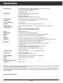
Specification .................................................... 30
Switching the Remote Control Level ........................ 26
Pin Assignment of EURO-AV Sockets
Universal Remote Control Handset
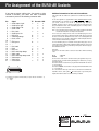
Pin Assignment of EURO-AV Sockets ....................... 31
Universal Remote Control Handset.......................... 27
Installation and Safety Precautions
POWER
STORE/CLEAR
EDIT/COPY
TUNING
DSR/FM
10 cm
+40
ATS
POWER
POWER
STORE/CLEAR
EDIT/COPY
TUNING
DSR/FM
ATS
POWER
STORE/CLEAR
EDIT/COPY
TUNING
DSR/FM
ATS
STORE/CLEAR
EDIT/COPY
TUNING
DSR/FM
ATS
+5
POWER
STORE/CLEAR
EDIT/COPY
TUNING
DSR/FM
ATS
0
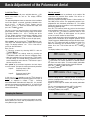
This satellite receiver is intended for reception of picture and
sound signals. Any other application is expressly prohibited.
Protect Your Environment!
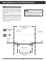
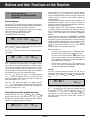
Make absolutely sure that your receiver is not exposed to dripping or splashing water. Protect the receiver from moisture.
Attention!
In addition, ensure that the ventilation openings are never
obstructed.
Do not place your receiver near sources of heat.
Do not throw used batteries from the remote control handset
in the household waste. Dispose of the batteries at a special
collecting point.
Heat build-up in the receiver is a source of danger and reduces the receiver´s operating life.
These operating instructions are printed on chlorine-free
paper which helps to protect the environment.
When operating the receiver in a wall unit (or in a camper, for
example), maintain distances of at least 10 cm – see illustration.
For reasons of ecology, always switch off the receiver with its
mains switch when it is not used for a longer time.
Always keep in mind: Even with the low standby power consumption of 10 W, you will consume 70 kWh within one year.
Even when switched off, the unit may be damaged by lightning striking the mains and/or aerial lead.
During a thunderstorm, you should therefore always disconnect the mains and aerial plugs.
ķ3
Connection Examples
Magn. polarizer
45° skew (± current)
z
LN
GH
2,5
1
C
LN
B
C
LN
A
C
z
} Input
GH
11
OMT
MAG. POL.
or
Mot
Control lines for magnetic polarizer
L
ON
OFF
DC OUT
15V 0,8A
AUDIO OUT
See also the system presentations in the chapter "Basic Adjustment of the Polarmount Aerial".
ķ4
6
7
8
9
10
36V/2.5A
j
EURO AV VCR
POL.
GAW 8951
5
M1
EURO AV DECODER
93
4
M2
EURO AV TV
705
KU00
3
GND
É
B
R
B
Z
T
2
MAGN.
910 . . .2050MHz
14/19V 0.5A
220-240V~ 50/60Hz
1
5V/0.2A
STR 400 AP
xxxxxxxxxxxxxxxxxxx
n e
GND
ǵ
REM. CONTR. VCR
0/12V/0.1A
ɯ
INPUT-SAT
A
AGC
alternatively for motor-driven polarizer
220-240V~
50-60Hz
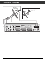
Connection Examples
Remote Control (Timer)
VCR
Decoder
STR 400 AP
Ant.
Control
ASTRA
TV
TV
Decoder
VCR
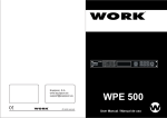
EURO-AV sockets for 1 VCR, 1 decoder, and TV
Radio
1) Terr. TV reception/SAT VCR recording.
terr. HF-Signal
L
2) SAT TV reception/terr. VCR recording.
R
HiFi-Amplifier
ŀ
ŀ
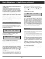
Two aerial systems can be connected to the aerial inputs of
the SAT receiver, for example:
3) Terr. TV reception/terr. VCR recording/SAT radio hifi reception.
4) For VCR playback, the signal path is automatically switched via the SAT receiver to the TV receiver (also in standby).
To 1) and 2)
Input A:
Rotary system. Control takes place via the
"Ant. Control." connections.
If a decoder is connected, this is automatically switched on
(evaluation of the switching voltage).
Input B:
Fixed aerial being directed at the Astra satellite.
On decoders without switching voltage, this can be activated
with respect to the programme position when programming
the receiver.
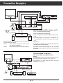
TV set with 1 EURO-AV- or 1 DIN socket /
video recorder (VCR) with 2 EURO-AV sockets /
decoder
EURO AV
DIN AV
AV 2
VCR
AV 1
This configuration is necessary if you wish to visualize info tables
from the video recorder on the picture screen of the TV set.
The required cable is a special Y-Scart cable. Please consult your
GRUNDIG after-sales service.
Y-Scart
Remote control (Timer)
STR 400 AP
Ant.
Control
ASTRA
TV
Decoder
VCR
terr. HF-Signal
TV
Radio
ŀ
L
R
HiFi-Amplifier
ŀ
Decoder
ķ5
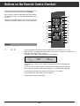
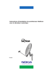
Buttons on the Remote Control Handset
Important operating functions and basic settings can be carried out with the universal remote control TP 720 SAT.
Please insert the battery included observing correct polarity.
The marking for this is on the compartment bottom. Close
the cover.
Change the exhausted battery in time. We cannot be held
reponsible for damages resulting from an exhausted battery.
1
2
3
4
5
6
7
8
Buttons
1
0…9
1
2
3
4
5
6
7
8
9
TV
0
AV
ATS
ķ A/B
AUX
RADIO
P+
+
AUDIO
OK
P-
F
TV
SAT
VIDEO
9
ßI
ß?
ß`
ßQ
ßW
ßE
ßR
ßT
ßZ
– The desired programme position is directly selected with the numeric buttons, e.g. 123.
When selecting a multi-digit programme position, the numbers are entered in sequence from
left to right. For example, enter 1, 2, and 3.
When you enter the digit 1, the following appears in the display:
I _ _ XXARDXXX
TIMER o p ü +
STEREO
SIGNAL IIIIIIIIIIIII
If no further entry is made, the unit switches automatically to the one-digit programme
position 1.
You can select up to 199 TV programme positions and 199 radio programme positions.
– Direct entry of the satellite’s transmission frequency, e.g. 11325 MHz (MHz indication).
– In audio mode, direct entry of the sound carrier frequency, e.g. 7.02 MHz.
– Timer programming: Entry of date, start and stop time.
– Switching the receiver on from standby.
ķ6
2
¢
3
4
.
-
Opens the Timer menu and switches back to the current programme.
5
] ¢
– Step-by-step programme position selection and switching on from standby.
– In Timer menu: Selection of menu points.
TV
Certain TV sets select automatically the AV mode when switching on the SAT receiver.
You can switch back to terrestrial reception mode by pressing the TV button.
¢
Shift button for switching to the second remote control level for a 2nd SAT receiver.**
“
¢
|
6
O
Confirms and saves certain values (e.g. in the Timer menu).
7
]
– In Timer menu: Selection of Timer positions.
x
“c
– In TV mode: Setting the volume level of the TV set.
|
– After pressing the
8
9
ßI
ß?
ß`
ßQ
ßW
ßE
ßR
ßT
ßZ
¢
F
button: Manual motor control for the Polarmount aerial.
¢
Shift button for switching the remote control between SAT receiver and TV control mode.
(This universal remote control handset can also be used for important functions of units of other
manufacturers).**
b
®
™
,
Switches the receiver to standby. Only possible via the remote control handset.
¢
¢
¢Ȅ
¢
RADIO
Switches between SAT-TV and SAT-radio mode.
AUDIO
Without function (Teletext function on certain TV sets).
TV
SAT
A/B
F
¢ʀ
¢
VIDEO
8 **button: For setting the brightness of the TV set.
Press together with the 8 **button: For setting the colour contrast of the TV set.
Press together with the
Without function (Teletext function on certain TV sets).
Without function (Teletext function on certain TV sets).
Activates manual motor run for the Polarmount aerial (motor control by means of the
buttons).
Press together with the
xc
8 **button: For muting the sound of the TV set.
Shift button for switching the remote control between SAT receiver and video recorder mode.
(This universal remote control handset can also be used for important functions of units of other
manufacturers).**
** See also chapter "Universal Remote Control Handset".
ķ7
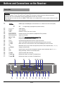
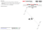
Buttons and Connections on the Receiver
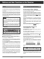
Front of Unit
Attention!
q? qQ
qE
</ > ( and ), and
Except of the buttons
Radio ( ), all buttons are locked to prevent inadvertent operation.
To clear the lock, press and hold down one of the locked buttons for more than 3 seconds.
¢
¢
When switching the receiver off with the POWER
activated again.
ßU
´?
´`
´Q
´W
´E
´R
´T
´Z
´U
qI
q?
q`
qQ
qW
qE
qR
qT
PANDA
¢ I Ǽ switch, or to standby with the remote control handset, the lock is
PANDA logo of Panda/Wegener Communications Inc.. Award for excellent sound quality.
´I
I99
21/2-digit display (for programme position number).
XXXXXXXX
8-digit display
STEREO
Stereo indication
TIMER
Indication; lit when Timer menu is active.
““““
Indication of active Timer position or programmed Timer positions.
SIGNAL IIIIIIIIIIIIIII
Signal level indication.
POWER
On/off switch. No disconnection from mains supply!
1
2
3
4
¢IǼ
¢ P/F
¢ V/H
¢ VIDEO
¢ AUDIO
¢<
¢ MEMORY
¢>
¢ʐ
¢ RADIO
¢ MODE ʺ
¢ MODE ɶ
Programme position/frequency selection.
Vertical/horizontal polarization and tuner input selection A/B.
16/22.5 and 25 MHz video frequency deviation and signal inversion selection.
Mono main carrier, mono subcarrier, and stereo Panda/Wegener carrier selection.
Downward step-by-step selection of programme positions and all adjustable data (... 3, 2, 1).
Storage of all preset data.
Upward step-by-step selection of programme positions and all adjustable data (1, 2, 3 ...).
Aerial positioning; submenu for aerial adjustment.
SAT/TV and radio mode switching.
Multifunction button (see chapter "The Mode Menu").
Multifunction button (see chapter "The Mode Menu).
ßU
´I
8
´?
9
199
DSF
Ǽ
15
12
13
14
TIMER
1
STEREO
SIGNAL IIIIIIIIIII
STR 400 AP
P/F
´R
11
ǵ
PANDA
POWER
´` ´Q ´W ´E
10
V/H
VIDEO
AUDIO
ʐ
MEMORY
MODE
RADIO
´T ´Z ´U qI q? q` qQ qW qE qR qT
16
17
18
19
20
21
ķ8
22
23
24
25
26
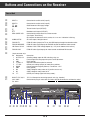
Buttons and Connections on the Receiver
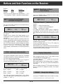
Rear of Unit
qZ
qU
wI
w?
w`
wQ
INPUT A
Connection for satellite aerial (input A).
INPUT B
Connection for satellite aerial (input B).
_
Ƕ
Ƕ _
On/Off button for LNC supply voltage.
É
Terrestrial aerial input (VHF/UHF).
ON...OFF
ɯ
wW
wE
wR
wT
wZ
wU
Modulator aerial output (VHF/UHF).
REM. CONTR. VCR
Connection for remote control via a video recorder
(see chapter "Timer Menu").
On reception of commands via this socket, the "VCR-REC" indication is flashing.
AUDIO OUT R/L
AF stereo output, left/right channel.
EURO AV TV
EURO-AV socket (output) for TV set, with RGB looping-through from decoder socket.
EURO AV DECODER
EURO-AV socket (input/output) for PAL/MAC decoder or additional video recorder.
LNC-Power 14/18 V
Individual 14/18 V LNC voltage adaption by ± 2 V (on the bottom of the receiver).
EURO AV VCR
EURO-AV socket (input/output) for video recorder or additional PAL decoder.
10-pin connector strip:
Pin
11
12
13
14
15
16
17
18
19
10
Connection
Switching voltage output for LNC switching, relay, etc.
Field strength measuring output for precise aerial adjustment.
Earth (ground)
Output for motor-driven polarizer, actuator.
Control pulse voltage (output) to motor-driven polarizer.
Current output for magnetic polarizer, ±70 mA/max. ±12 V
Earth (ground)
Supply voltage for rotary motor, 36 V (positive on east run).
Supply voltage for rotary motor, 36 V.
Control pulse voltage (input from rotary motor).
R
É
B
93
EURO AV DECODER
GAW 8951
j
EURO AV VCR
4
AUDIO OUT
OFF
qZ qU wI w? w` wQ wW
28
29
30
31
32
33
5
DC OUT
15V 0,8A
L
ON
27
EURO AV TV
705
KU00
3
wE
wR
34
35
ķ9
wT
40
wZ wU eI
36
37
38
6
7
8
9
10
36V/2.5A
910 . . .2050MHz
14/19V 0.5A
B
Z
T
2
M1
220-240V~ 50/60Hz
1
M2
STR 400 AP
n e
POL.
A
ǵ
REM. CONTR. VCR
GND
ɯ
INPUT-SAT
MAGN.
Connection for plug-in mains cable. Pull mains plug to disconnect the unit from the mains!
5V/0.2A
220 - 240 V ~
50 - 60 Hz
GND
15 V / 0.8 A output for connecting external units (e.g., decoder).
AGC
DC OUT 15 V / 0,8 A
0/12V/0.1A
eI
e?
Designation
0/12 V/0.1 A
AGC
GND
+5 V/0.2 A
–
–I I– POL.
MAGN.
GND
M2
M1
–
–I I–
220-240V~
50-60Hz
e?
39
Important Information
General
Selecting the Aerial Input
For the description of the unit´s functions, it is assumed that
the aerial has correctly been installed and that the receiver
has correctly been connected.
The receiver is provided with two aerial inputs. Preprogramming in the factory has been made for the standard solution,
comprising one LNC with frequency switching by means of a
14/18 V supply voltage, and polarization switching by means
of a magnetic or mechanic polarizer.
If you wish to implement different solutions, such as, for
example, two-cable distribution in the first IF level (separate
H/V), several aerials, or multi-feed mode, it is necessary to
activate the second aerial input with respect to the programme position.
Button Lock
Attention!
</ > buttons
Press the
V/H button twice, then use the
to select input A
or B . The display indicates, for example:
¢
</ > and
Except of the
Radio buttons, all buttons
are locked to prevent inadvertent operation.
To clear the lock, press one of the locked buttons for more
than 3 seconds.
¢
¢
qU
I99 INPUTXAX
When switching the receiver off by means of the POWER
I switch, or with the remote control handset to standby,
the lock is activated again.
¢
qZ
Ǽ
¢
TIMER o p ü +
STEREO
SIGNAL IIIIIIIIIIIII
¢
MEMORY button.
Store the setting with the
The display indicates again the current programme position.
Connecting the SAT Receiver to the Television
See also section "Adapting the Polarizer, Installation Menu".
If there should be interferences visible in the form of spikes
(short black or white lines), these can be eliminated by optimizing the input frequency setting. For this, press the
P/F
button and adjust the value giving the best picture on the TV
</ > buttons.
screen by means of the
Store the corrected value in memory by pressing the
MEMORY button.
Best picture quality is obtained when the receiver and the
television are connected by means of a EURO-AV cable (see
connection example). If you possess a television without
EURO-AV socket, make the connection via the built-in modulator with a coaxial cable. The modulator is preset to
channel 36.
¢
¢
¢
If this channel should already be occupied by your video
recorder or a terrestrial station, it is possible to change the
channel (see paragraphe "Modulat. – Adjusting the Modulator
Channel"). You have the choice between channel 25 and
channel 60. The televison must also be tuned to this channel.
Hint
The receiver is already preprogrammed to all current programmes from a number of satellites.
See the yellow pages: "Station Table of the Satellite Stations".
16:9 Switching
If you wish a different programme order, it is very easy to
change the existing order.
If a switching voltage (6 V) for the 16:9 picture format is present on the EURO-AV DECODER or VCR socket, this will be
evaluated and passed to the EURO-AV TV socket. Correspondingly equipped TV sets then are automatically switched to
the 16:9 format.
For detailed information, see the corresponding explanation
(SORT function in the chapter "The Mode Menu").
ķ 10
Basic Adjustment of the Polarmount Aerial
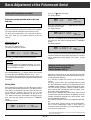
General
A polarmount aerial is constructed so that the imaginary line,
on which the satellites are orbiting at a distance of 36000 km
above the equator, can be followed by a single control function of the motor.
There are a number of different motor types and motor
fixings.
The action radius of the aerial (max. deflection to the east and
the west) can be restricted by limit switches inside the motor,
or by mechanical end stops. This is especially necessary to
protect the aerial from running against obstructions (walls,
trees, etc).
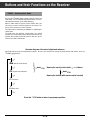
In addition, the receiver is provided with electronic limit switches (similar to tab stops on a typewriter) for restricting the
action radius of the aerial.
Attention!
It is not allowed to use these limits to protect the aerial
from running against obstructions. If a test run should be
necessary for adjustments at a later date, these limits
would be overridden and the aerial thus could be damaged. The following illustration shows the relations.
mech. action radius of aerial
Maximum stroke
restricted by electrical limit switches
or mechanical end stops.
mechanical or electrical
end stop (East)
Motor
mechanical or electrical
end stop (West)
Motor
Position 0000
= zero point
Limit 1
e.g. 0020
set limits
L 2
L 1
(restricted action radius)
Different satellite positions
within the set limits.
63°
23°
19°
16°
In programme mode, the aerial runs
only to these positions,
not to the limits.
ķ 11
Limit 2
e.g. 0650
Basic Adjustment of the Polarmount Aerial
ʐ button once again.
Press the
The display indicates:
Setting the Zero Position and Limits
¢
I99 XL2XXX20
Driving the exactly mounted aerial to the east
end stop
It is absolutely necessary to execute this step.
Press and hold down the
reached its west end stop.
The display indicates:
Before setting the limits L1 (East) and L2 (West), it is absolutely necessary that the aerial has been driven to its mechanical east end stop for setting the internal counter to zero.
¢ > button until the aerial has
I99 WESTXEND
The aerial must be mounted in such a way that no obstructions (trees, walls, etc.) can hinder its travel to its east end
position.
TIMER o p ü +
STEREO
SIGNAL IIIIIIIIIIIII
TIMER o p ü +
STEREO
SIGNAL IIIIIIIIIIIII
< button to let run the aerial approx. 20 impulPress the
ses to the east, then store the setting with the
MEMORY
button.
The display indicates:
¢
¢
Follow these steps:
Switch the unit on.
Press the
ʐ button 3 times.
The display indicates, for example:
¢
I99 XL1XX414
Press the
I99 XLIMITX2
TIMER o p ü +
STEREO
SIGNAL IIIIIIIIIIIII
TIMER o p ü +
STEREO
SIGNAL IIIIIIIIIIIII
You can connect to the receiver motors delivering max. 7999
impulses between the east and west end stops. The impulses
can be generated by Reed contacts, Hall sensors, or opto
couplers.
¢ < button to drive the aerial to the east.
Attention:
If the aerial should run in opposite direction, it is necessary to exchange the connections M1 and M2 on the terminal strip
of the receiver.
Adapting the Receiver to Different
Aerial Systems with Different
Feed-in Systems (LNC´s).
wU
< button until the east end stop
Press and hold down the
is reached, giving the following indication: "EAST END ".
This represents the zero position of the internal counter and
is the reference point for all satellite positions programmed at
a later date.
¢
Today, there exist a variety of very different LNC types with
different local oscillators and control commands for frequency and polarization switching.
It is necessary to adapt the receiver to the used feed-in
system.
For rotary systems, LNC´s with switchable frequency range
are used. Polarization switching can be effected by means of
a 14/18V* supply voltage or magnetic/motor-driven polarizers. You can also use feed-in systems (reception systems)
with 2 separate LNC´s for different frequency ranges (including a wave-guide separating filter).
Your receiver is provided with 2 aerial inputs (Input A, Input
B) which make it possible to connect an additional aerial (for
example, permanently pointing at the Astra satellite, which
then is permanently available).
The following illustrations show several application possibilities.
The receiver offers a choice of three system configurations.
These system configurations enable a large number of
connection variants and make it very easy to adapt the receiver to the aerial system used.
Setting limits
When searching new satellites at a later date with the help of
the manual aerial positioning function, it may happen that the
limit switches or mechanical end stops (crash) are often run
to. To avoid this, electronic limits can be set at a short
distance in front of these end positions. For this, press the
> button to let run the aerial approx. 20 impulses to the
west, then store the setting by pressing the
MEMORY
button.
The display indicates:
¢
¢
I99 XLIMITX1
TIMER o p ü +
STEREO
SIGNAL IIIIIIIIIIIII
ķ 12
* 14/18 V LNC individually adaptable by ± 2 V (see
Connections / Rear of unit).
wT in section "Receiver Buttons and
Basic Adjustment of the Polarmount Aerial
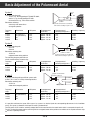
System 1
14/18 V
12/0 V
0/22 kHz
Frequency switching with
14/18 V, e.g., Grundig package STP 400/STP 300 A,
or 0/12 V, e.g., Grundig package STP 300,
or with 0/22 kHz, e.g., future Astra solution.
A
magnetic or motor-driven
polarizer
Polarization switching:
exclusively with motor-driven
or magnetic polarizer.
Frequency
range
11 GHz
11 GHz
12 GHz
12 GHZ
INPUT-SAT
11/12
GHz
910 . . .2050MHz
14/19V 0.5A
possible connection for second aerial
with control according to sytem 1 or 2.
Polarization
LNC power
V1 (vertical 1)
H1 (horizontal 1)
V2
H2
14 V
14 V
18 V
18 V
Preprogrammed
skew value
approx. +30 mA
approx. –30 mA
approx. +18 mA
approx. –18 mA
Preprogrammed
switching voltage value
12 V
12 V
10 V
10 V
System 2
B
ON
Switching frequency
10 kHz
10 kHz
22 kHz
22 kHz
12/0 V
0/22 kHz
Frequency switching with
0/12 V or
0/22 kHz
INPUT-SAT
11/12
GHz
A
magnetic or motor-driven
polarizer or 14/18 V
Polarization switching with
14/18 V or
magnetic/motor-driven polarizer.
possible connection for second aerial
with control according to sytem 1 or 2.
910 . . .2050MHz
14/19V 0.5A
B
ON
The switching frequency 0/22 kHz can
also be used for driving a coaxial relay.
Frequency
range
11 GHz
11 GHz
12 GHz
12 GHZ
Polarization
LNC power
V1 (vertikal 1)
H1 (horizontal 1)
V2
H2
14 V
18 V
14 V
18 V
Preprogrammed
skew value
approx. +30 mA
approx. –30 mA
approx. +18 mA
approx. –18 mA
Preprogrammed
switching voltage value
12 V
12 V
10 V
10 V
Switching frequency
10 kHz
10 kHz
22 kHz
22 kHz
magnetic or motor-driven
polarizer or 14/18 V
System 3
INPUT-SAT
Frequency switching with input A/B for systems with
2 LNC´s (A: 11 GHz, B: 12 GHz) and waveguide filter.
11 GHz
910 . . .2050MHz
14/19V 0.5A
Polarization switching with
14/18 V or
motor-driven/magnetic polarizer.
Frequency
range
11 GHz
11 GHz
12 GHz
12 GHZ
A
12 GHz
B
waveguide filter
Polarization
LNC power
V1 (vertikal 1)
H1 (horizontal 1)
V2
H2
14 V
18 V
14 V
18 V
Preprogrammed
skew value
approx. +30 mA
approx. –30 mA
approx. +18 mA
approx. –18 mA
Preprogrammed
switching voltage value
12 V
12 V
10 V
10 V
ON
Switching frequency
10 kHz
10 kHz
22 kHz
22 kHz
It is possible to allocate the inputs A/B to sytem 1 or system 2 as desired (make the corresponding adjustments in the installation
menu). For system 3, allocation of the inputs A and B is predetermined.
The LNC power 14/18 V and the switching voltage 0/22 kHz are transferred via the coaxial cable which is connected to input A or B.
The 0/12 V switching voltage and the control signals for a magnetic/motor-driven polarizer are available at the 10-pole connector strip
and must separately be wired.
wU
ķ 13
Basic Adjustment of the Polarmount Aerial
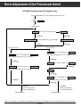
STR 400 AP installation mode (LNC frequency entry)
Press and hold down the
¢ V/H button and switch the unit on.
Indication INSTALL
after 3 seconds.
INPUT A with
INPUT B
¢ </ > buttons switch to
¢ MODE ɶ
SYSTEM 1, 2 or 3
¢ MODE ɶ
system selection with
¢ </ > buttons
¢ MODE ɶ
with system 1 or 2
SYSTEM 1, 2 or 3
¢ MODE ɶ
with system 3
LOC OSC1 with
LOC OSC1 with
¢ </ > buttons, e.g. 9750 MHz
then change frequency with ¢ </ > buttons
¢ MODE ɶ
¢ </ > buttons, e.g. 9750 MHz
then change frequency with ¢ </ > buttons
¢ MODE ɶ
INPUT A with
LOC OSC2 with
¢ </ > buttons, e.g. 10750 MHz
then change frequency with ¢ </ > buttons
¢ </ > buttons, e.g. INPUT B
¢ MODE ɶ
SYSTEM 3
¢ MODE ɶ
LOC OSC1 with
¢ MODE ɶ
¢ MEMORY
¢ </ > buttons, e.g. 10750 MHz
then change frequency with ¢ </ > buttons
¢ MODE ɶ
¢ MEMORY
store in memory and
close installation menu
Main programme
With the
store in memory and
close installation menu
Main programme
¢ P/F button, you can abort the installation menu from any menu option. In this case, the changed settings are not stored in
ķ 14
Basic Adjustment of the Polarmount Aerial
How to proceed:
Installation Menu
At first, the aerial must be positioned at the satellite. We
recommend the powerful Astra satellite. This will be explained in the following example.
Select the programme position number 1 (Astra satellite, 19°
East, ARD) on the receiver. This programme position is preprogrammed with horizontal polarization H1. The default
impressed current for the polarizer is to be optimized by performing the following steps:
Press the
ʐ button to switch the receiver into the manual
< button to run to limit
aerial positioning mode. Press the
> button to search the Astra 19° East
1, then press the
satellite. If the picture of ARD appears on the picture
screen, the correct satellite has been found.
If you should not be able to find this programme, change the
polarity of the connections of the magnetic polarizer on the
10-pole connector (MAGN:/GND) and repeat the above steps.
Press the
ʐ button once again to display the signal level.
< or
>
Adjust the maximum level by means of the
button. Press the
V/H button and then the
MODE ɶ
button.
The display indicates, for example:
¢
With the unit switched off, press and hold down the
V/H
button and switch the unit on. The display indicates
"INSTALL".
The preceding diagram shows an overview of the installation
menu. After approx. 3 seconds, the display indication chan</ > buttons, you can
ges to "INPUT A". With the
switch to "INPUT B". Select the desired aerial input, then
press the
MODE ɶ button.
¢
¢
¢
You pass to the next menu item where the frequency of the
local oscillator 1 (lower LNC frequency range) will be asked.
The display indicates "LOC OSC 1". Pressing one of the
</ > buttons switches to the frequency indication. Select
</ > buttons (hold down the
the desired value with the
corresponding button to let scroll the values at high speed).
¢
¢
¢
¢
With system 1 or 2, pressing the
MODE ɶ button switches to the 2nd oscillator frequency (upper LNC frequency
range). The display indicates "LOC OSC 2". Enter the frequency as described above.
¢
¢
¢ ¢
¢
¢
Next, you can...
– if necessary, proceed by selecting INPUT B with the
MODE ɶ button.
– store in memory the settings made by pressing the
MEMORY button (this will close the installation menu).
– abort the installation menu by pressing the
P/F button.
The old settings are restored and the installation menu is
closed. Aborting the menu with the
P/F button is possible from any menu item.
¢
¢
I99 SKEWXX72
TIMER o p ü +
STEREO
SIGNAL IIIIIIIIIIIII
¢
The polarizer current can be adjusted by pressing the
</ > button. The correct adjustment is situated between
the black and white spikes. To avoid multiple polarization
rotations, the smallest required value should be adjusted.
Press the
MODE ɶ button once again.
The display indicates:
¢
¢
With system 3, the oscillator frequencies for both inputs
must be entered. The inputs A and B a permanently allocated:
Input A:
Frequency band 11 GHz.
Polarizations V1, H1.
Input B:
Frequency band 12 GHz.
Polarizations V2, H2.
¢
I99 SKEWXALL
¢
In this case, it is not possible to use the
V/H button to
directly switch during normal operation between the inputs A
and B, as explained in chapter " V/H – Selecting
Vertical/Horizontal Polarization and Input A/B". It is possible
to freely select between the polarizations V1, H1 (input A) and
V2, H2 (input B). Switching between the inputs then is performed automatically.
TIMER o p ü +
STEREO
SIGNAL IIIIIIIIIIIII
¢
Memory button. All programme
Store the setting with the
positions preprogrammed with H1 now will successively be
set to this optimum value.
Repeat the same steps for stations with vertical polarization
V1.
For this, select programme position 3 (RTL in Germany).
Press the
V/H and then the
MODE ɶ button.
The display indicates, for example:
¢
¢
¢
I99 SKEWXX23
Adapting the Polarizer
If you should have selected a system with magnetic or motordriven polarizer, this must also be preadjusted, as there are
many different types available.
ķ 15
TIMER o p ü +
STEREO
SIGNAL IIIIIIIIIIIII
Basic Adjustment of the Polarmount Aerial
Adjust the optimum skew value as explained above, press the
MODE ɶ button once again, and store the setting with the
MEMORY button.
From this point on, all programme positions preset with vertical polarization are automatically set to this optimum value.
Manual motor control with the remote control
¢
¢
¢
ßR
After pressing the
) button, you have 8 seconds for
F (
manually controlling the motor with the
buttons.
Pressing the
button stores the new aerial position in
memory.
x c
O
As a number of satellites are not fixed exactly according to
the polarmount method, it may happen that certain programmes need an individual correction. To do this, use the SKEW
menu option and not the SKEW ALL menu option.
The display indicates, for example:
I99 XMANX132
To adjust the optimum skew value for the upper frequency
range (12.5 GHz), it is necessary to search a further satellite
(e.g., Kopernikus) and to adjust a station with V2 respectively
H2 following the already explained adjustment method.
TIMER o p ü +
STEREO
SIGNAL IIIIIIIIIIIII
Neutral adjustment
It is possible to connect in addition to the rotary aerial a fixed
aerial to your receiver. For example, the rotary system to
input A and an aerial which is permanently directed at the
Astra satellite to input B (see chapter "Connection Examples").
The skew values V2 and H2 have no influence on the values
of H1 and V1. The SKEW ALL function can be used again and
greatly facilitates programming.
The position of the rotary system should not change when
switching to a programme position used with the fixed aerial.
Enter "0°" as position for the satellite whose programmes you
wish to receive by means of the fixed aerial. The display then
indicates "-- " instead of a value for the satellite position. The
rotary system then will keep its orientation (position).
Storing the Satellite Position in Memory
After having made the above explained adjustments, the position of the Astra satellite should be stored in memory. For
this, press the
ʐ button.
The display indicates, for example:
¢
Adjustment Run
I99 XMANX132
TIMER o p ü +
STEREO
SIGNAL IIIIIIIIIIIII
One of the outstanding features of your receiver is the precise
aerial run to the preset satellite positions.
MODE ɶ or
MODE ʺ button.
Then, press the
The display indicates, for example:
¢
If the receiver is inadvertently switched off during an aerial
run, the impulses from the idling aerial motor are no longer
counted, resulting in an erroneous positioning for all
satellites.
By means of an adjustment run which is automatically started
when switching the receiver on again, the aerial is first driven
to its east end stop for correcting the bad positioning, then
the aerial is exactly positioned to the previously selected
satellite.
¢
I99 EASTX19 °
TIMER o p ü +
STEREO
SIGNAL IIIIIIIIIIIII
¢
MEMORY button to conclude storing.
Press the
All programmes of the Astra satellite with the pulse number
indicated in the MAN menu option (manual aerial adjustment)
are now stored with the position 19° East.
An adjustment run might also be necessary for other reasons, for example, if a position offset is caused by strong and
lasting external impulses.
To start the adjustment run, keep pressed the
ʐ button
while switching on the unit. Automatic correction of the position is effected as described above.
¢
Following this method, you can store all satellites from east
to west:
Select a programme position for the satellite concerned,
search the satellite using the MAN menu option, and optimize
the signal level in the LEV menu option (to get the signal
strength indication, press the
ʐ button). Then call up the
satellite position menu function (press the
MODE ɶ or
ʺ
MODE button) and store the setting by pressing the
MEMORY button.
If the motor drive should inadvertently start running when
calling up the programme position of a satellite which is not
yet stored in memory, motor run can be stopped by pressing
It is possible to abort an adjustment run by pressing the
¢ P/F button.
¢
¢
¢
¢
ķ 16
Buttons and their Functions on the Receiver
¢ P/F – Selecting Programme/Frequency
General
As already stated, the receiver has been preprogrammed at
the factory for the main programmes from the most important satellites.
If you wish a different programme order or intend to correct
adjustments, this can easily be done by means of the buttons
on the front of the receiver and, in certain cases, with the buttons on the remote control handset. However, this should
only be done after having carried out the basic adjustment of
the polarmount aerial.
Ku-Band reception (10700 to 13000 MHz)
¢
Use the
P/F button to switch between programme position mode and frequency entry mode.
The display indicates the programme positions 1 to 199 or, in
frequency entry mode, 10700 to 13000 MHz. Real reception,
however, is only possible in the frequency range for which the
used LNC has been designed. In this mode, direct frequency
entry with the numeric buttons of the remote control handset
is possible.
> button will change the
Pressing and holding down the
frequency in steps of 10 MHz in upward direction, and hol< button in steps of 3 MHz in downward
ding down the
direction.
This allows you to scan the entire frequency range at high
speed in forward direction, and at lower speed in reverse
direction.
With single step tuning, the frequency is changed in steps of
0.5MHz, which corresponds to the finetuning function.
¢
Attention!
¢
The buttons on the front of the receiver, except the
</ > and
RADIO buttons, are electronically locked
to prevent that the receiver programming be changed by
inadvertent operation of the buttons (for example, when
wiping off dust).
To clear the electronic lock, press on any of the locked
buttons for more than 3 seconds. When switching the unit
off or to standby, the electronic lock is activated again.
¢
¢
Generally applies:
Particularities when receiving S- and
C-band satellites (2.5 ... 4 GHz)
199
POWER
For receiving the 2.5 … 4 GHz frequency bands, special aerials and LNC´s are necessary.
ǵ
PANDA
Ǽ
DSF
TIMER
1
STEREO
SIGNAL IIIIIIIIIII
For receiving stations on these frequency bands with your
unit, you must observe the following:
STR 400 AP
P/F
V/H
VIDEO
AUDIO
MEMORY
ʐ
RADIO
MODE
The value 10000 MHz must generally be entered in the installation menu as local oscillator frequency for the LNC, not the
actual value of the LNC.
● Certain functions can be called up by pressing these buttons once or several times.
ǵ Preset functions can be modified with these buttons.
X Settings and corrections made are stored in memory by
ǵ
pressing the
MEMORY button.
¢
When adjusting the frequency for the programme position
concerned ( P/F button), do not enter the transmission frequency of the satellite, but the output frequency of the LNC
(first intermediate frequency = IF 1).
You can calculate the IF 1 by subtracting the transmission
frequency of the satellite from the actual local oscillator frequency.
¢
´R
When switching the receiver on with the power switch , it
switches automatically to the last selected programme position (Last Station Memory).
The desired programme positions are selected by means of
</ > buttons on the receiver or the programme select
the
buttons ] | or numeric buttons on the remote control
handset.
¢
E.g.
The display indicates the number of the selected programme
position and the associated station name. If the new station
belongs to a different satellite, the aerial will be positioned to
this satellite and the new satellite position is briefly indicated
in the display.
Local oscillator frequency:
– Satellite transmission frequency:
= Result (IF 1):
5100 MHz
– 3900 MHz
= 1200 MHz
To enter this value, first press the "0" button. The display indicates:
I99 X1____Mz
To switch the receiver on from standby, press one of the programme select buttons ]| or of the numeric buttons on
</ > buttons on the
the remote control handset, or of the
receiver. In this case too, the last selected programme position will be selected again (Last Station Memory).
TIMER o p ü +
STEREO
SIGNAL IIIIIIIIIIIII
In this case (S- and C-band reception), the first figure "1" has
no physical meaning. Then, enter the value for the IF 1. For a
three-digit value, an additional "0" must be entered at the first
position.
¢
ķ 17
Buttons and their Functions on the Receiver
Examples:
IF 1:
1200 MHz
950 MHz
Entry:
01200
00950
¢ AUDIO – Mono/Stereo and Sound
Indication:
11200 Mz
10950 Mz
Carrier Switching
Please also observe setting of the video deviation –1, –2 or
–3 (see paragraphe " Video – Adjusting the Video Deviation").
¢
Press the
AUDIO button to indicate the current audio
mode in the display, for example:
¢
I99 MONOX <X >
¢ V/H – Selecting Vertical/Horizontal
Polarization and Input A/B
By repeatedly pressing the
between:
¢
Press the
V/H button to indicate the current polarization in
the display, e.g., (H1 18 V)
I99 H1X18VX-
TIMER o p ü +
STEREO
SIGNAL IIIIIIIIIIIII
On STEREO, the indication "STEREO" appears in addition on
< or
> butthe display
of the receiver. Press the
ton to indicate the actual value of the set frequency, for example:
´`
¢
¢ </ > – Down/Up Setting Buttons
The frequency-modulated satellite signals are transmitted
with different deviations. To obtain a good picture, the receiver must be adjusted correspondingly.
</ > buttons to select
When in programme mode, use the
the next programme position down or up.
</ > buttons are used for chanIn the other modes, the
ging the entered data.
When holding down the corresponding button, the programme positions or data values are selected and displayed at
high speed.
¢
¢
¢
Press the
VIDEO button to indicate on the display the
video deviation and video polarity, e.g., (DEV. 3).
TIMER o p ü +
STEREO
SIGNAL IIIIIIIIIIIII
</ > buttons will switch to
When in standby, pressing the
the last selected SAT programme position (Last Station
Memory).
¢
¢ </ > buttons:
DEV. –2 = 22.5 MHz,
DEV. 3 = 16 MHz,
DEV. –3 = 16 MHz.
¢
Direct frequency entry is possible with the numeric buttons of
the remote control handset. Tuning will be effected only after
having entered the third frequency digit.
¢ VIDEO – Adjusting the Video Deviation
DEV. 2 = 22.5 MHz,
TIMER o p ü +
STEREO
SIGNAL IIIIIIIIIIIII
¢
¢
DEV. –1 = 25 MHz,
¢
You can adjust the frequency between 5.00 MHz and
9.99 MHz in steps of 10 k Hz.
< or
> button will
Pressing and holding down the
scan the frequencies at high speed.
¢
DEV. 1 = 25 MHz,
¢
I99 X7 . 02MH z
Press the
V/H button once again to indicate on the display
</ > buttons
the input which is to be selected with the
("INPUT A" or "INPUT B"). See also the sections "Adapting the Polarizer, Installation Menu", and "Selecting the Aerial
Input".
The video deviation is selected with the
¢ AUDIO button, you can select
MONO < > = Main carrier, Mono wide,
MONO > < = Subcarrier, Mono Panda Wegener,
STEREO
= Panda carrier*, Stereo.
</ > buttons, you can select between V1, H1,
With the
V2, and H 2.
Allocation of the respective LNC voltage depends on the
selected LNC system (see paragraphe "Setting Zero Position
and Limits").
For LNC´s with magnetic polarizer, the optimum skew value
must be adjusted after having selected the polarization (see
also paragraphe "SKEW ALL – Transferring the Skew Value").
I99 DEV. X3XX
TIMER o p ü +
STEREO
SIGNAL IIIIIIIIIIIII
¢ MEMORY – Storing Data in Memory
For C-band and S-band reception with 4- resp. 2.5GHz
LNC´s, the video signal must be inverted by selecting the setting DEV. –1 … DEV. –3.
Pressing the
¢ MEMORY button stores all data in memory.
*Panda/Wegener Communications Inc.. Award for highest tone quality.
ķ 18
Buttons and their Functions on the Receiver
¢ ʐ – Aerial positioning /
You can allocate a value between 99° East and 99° West by
< or
> button. In this way, you can allomeans of the
cate the satellite position the number of degrees at which the
satellite stands in the orbit (see also section “Storing the
satellite position“).
This allocation has already been done at the factory for the
preprogrammed satellites. Prior to storing a position in
memory, the aerial must be directed exactly at the corresponding satellite (as described further up).
The degree number of the satellite position is allocated the
actual pulse number of the motor. This makes sure that the
aerial is automatically driven into the correct position (pulse
number of the aerial motor) when selecting a programme
position.
If you press twice on one of the
MODE ɶ or
MODE ʺ
buttons when in the MAN (manual aerial adjustment) or LEV
menu option, you can change or allocate a new name with the
help of the remote control handset. You can change the flashing character on the display with the cursor buttons ] |
on the remote control handset. Use the cursor buttons
to displace the flashing entry position.
¢
designating the satellite position
and station
Aerial positioning
Pressing the
ʐ button calls up a submenu with functions
for adjusting the aerial and naming the stations and satellites.
The diagram below provides you with an overview.
These functions have already been explained in the chapter
"Basic Adjustment of the Polarmount Aerial".
Press the
ʐ button (for the first time).
The display indicates, for example:
¢
¢
¢
¢
I99 XMANX290
TIMER o p ü +
STEREO
SIGNAL IIIIIIIIIIIII
In this menu option, it is possible to manually drive the aerial
between two set limits L1 (East) and L2 (West) by pressing
< and
> button, respectively.
the
¢
xc
¢
Now it is possible to:
¢ ʐ button a second time. The display indicates,
Press the
for example:
I99 XLEVXX74
¢
¢
Save the current setting with the O button on the
remote control handset. You pass automatically to the
Save the current setting with the
MEMORY button
on the receiver. You return to the programme mode.
TIMER o p ü +
STEREO
SIGNAL IIIIIIIIIIIII
next programme position the station designation of
which now can also be changed.
When in this menu option, the numeric value of the reception
level is indicated. The resolution of this indication is much
higher than the bar display following the "SIGNAL" lettering
(at the right in the display). With the help of the level indicati</ >
on, it is possible to adjust the aerial by means of the
buttons to optimum reception fieldstrength. (In the vicinity of
the maximum value, press the buttons only briefly).
¢
Quit the menu by pressing the
P/F button on the
receiver. You return to the programme mode without
saving the changed station designation.
¢
Example:
You have selected programme position 184 and wish to
change the station name. For this, press one after the other
the buttons
ʐ MODE ɶ MODE ʺ . The display indicates:
Press the
ʐ button once again. The display indicates
"L1 ...". In this menu option, you can set the east limit with
</ > buttons. When the east end stop is reached, the
the
display will indicate "EAST END".
¢
¢ ¢
¢
¢
I84Xfl
ARDXX
Press the
ʐ button once again. The display indicates
"L2 ...". In this menu option, you can set the west limit with
</ > buttons. When the west end stop is reached, the
the
display will indicate "WEST END".
¢
¢
The letter "A" of "ARD" is flashing (for stations without name,
"fl
" will appear). You can change this character with the
cursor buttons ] | (character sequence: A, B, C, … X,
Y, Z, blank, 0, 1, … 8, 9, A, B, C ...). When pressing
, the
second place "R" will flash and can be changed in the same
way. After having entered the desired name, continue as
described above.
c
Designating the satellite position and station
Through pressing one of the
MODE ɶ and
MODE ʺ
buttons when you are in the aerial menu ( ʐ), you can
designate the satellite position: in degrees of EAST or WEST
direction. The display indicates, for example:
¢
¢
¢
I99 EASTX19 °
TIMER o p ü +
STEREO
SIGNAL IIIIIIIIIIIII
TIMER o p ü +
STEREO
SIGNAL IIIIIIIIIIIII
ķ 19
Buttons and their Functions on the Receiver
¢ RADIO – Selecting Radio Mode
¢
Pressing the
RADIO button toggles between SAT/TV and
radio mode. The unit automatically switches to the last selected programme position (Last Station Memory).
When in radio mode, the picture screen remains dark. You
can correct set values with the buttons on the receiver. The
picture screen shows the current TV picture.
The radio mode is indicated by an additional "R" following the
station name.
To benefit from the optimum sound quality, you should
connect the L and R phono (Cinch) sockets of the receiver via
a phono (Cinch) cable to your hifi system. In this case, the TV
receiver can remain switched off.
Overview diagram of the aerial adjustment submenu
Button for calling up the aerial adjustment functions. To access the submenu for naming the aerial position and stations, press the
MODE ɶ / ʺ buttons.
¢
¢ʐ
MAN (Manual aerial control)
¢ʐ
LEV (Signal level indication)
¢ʐ
¢
MODE ɶ / ʺ
Naming the aerial position (with
¢ </> buttons)
¢ MODE ɶ/ ʺ
Naming the station (with remote control handset)
L1 (East limit)
¢ʐ
L2 (West limit)
¢ʐ
Press the
¢ P/F button to return to programme position.
ķ 20
The MODE Menu
Overview
Normal case (e.g. programme mode)
¢ V/H (e.g. "H 1 18 V")
¢ P/F (e.g. "11494 MHz")
¢ VIDEO (e.g. "DEV 1")
¢ AUDIO (only with "MONO < >")
¢ MODE ɶ ¢ MODE ɶ
➞
COPY (copy programme)
¢ MODE ɶ
¢ MODE ɶ
¢ MODE ɶ
ɶ
➞ ¢ MODE
¢ MODE ɶ
¢ MODE ɶ
ɶ
➞ ¢ MODE
MODE ɶ
¢
ɶ
➞ ¢ MODE
¢ MODE ɶ
¢ MODE ɶ
¢ MODE ɶ
ɶ
➞ ¢ MODE
¢ MODE ɶ
¢ MODE ɶ
¢ MODE ɶ
¢ MODE ɶ
¢ MODE ɶ
¢ MODE ɶ
¢ MODE ɶ
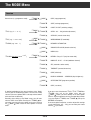
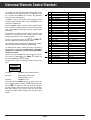
A detailed explanation of the menu functions of the "Mode"
menu is given in the following sections. The menu has a loop
structure (the menu options COPY at the top and the bottom
of the overview are identical).
SORT (exchange programme)
O VOLT/12 VOLT (switching voltage)
SKEW: –99 … 128 (polarizer adjustment)
SKEW ALL (transfer skew value)
WIDE/NARROW (IF bandwidth)
DECODER: AUTOMAT./0N
VID ONLY/VID & AUD (decoder selection)
NORM 1/2/3
DEEMPH.: 50 µs/J 17 (only for mono wide)
MODULAT.: CH 25 … CH 60 (modulator channel)
ATS (automatic station search)
TIME/DATE (summer/winter time)
CODE (child lock)
DISPLAY: MINIMUM … MAXIMUM (displ. brightness)
ACTIVE/INACTIVE (programme position)
COPY (see above)
¢
¢ ¢
If you press one of the buttons
V/H,
P/F,
VIDEO or
AUDIO, then call up the "Mode" menu with the
MODE ɶ button, you arrive directly at the menu option
which is of great importance for the corresponding function
(e.g., pressing first
VIDEO, then
MODE ɶ , calls up the
DECODER menu option).
¢
¢
¢
Normally, when calling up the "Mode" menu, you will start
with the COPY menu option. Pressing the
MODE ɶ button brings you from one menu option to the next. Pressing
the
MODE ʺ button selects the menu options in reverse
order.
¢
¢
If one menu option comprises a number of possible settings
(e.g. 0 Volt/12 Volt, –99 ... 128), you can make your choice
</ > buttons.
with the
¢
¢
ķ 21
The MODE Menu
Use the
MODE ɶ / ʺ buttons to select the individual setting functions. Changing the settings in the respective mode
</ > buttons or with the
then is carried out with the
numeric buttons on the remote control handset.
SORT
¢
¢
"SORT " is indicated on the display. With this function, the
programme positions are exchanged.
Select the programme position you wish to exchange by
</ > buttons on the receiver or the numeric
pressing the
or programme select buttons ] | on the remote control
handset. The programme position number will flash.
Pressing the
MEMORY button executes the sort function
and the programme positions are exchanged.
Repeated pressures on the ¢ MODE ɶ / ʺ buttons will bring
you to the menu options (functions) of the "Mode" menu.
These menu options are explained in the following.
¢
¢
COPY
By repeatedly applying the "SORT" function, the programme
positions can be brought into a new order.
With this menu function, you can copy all parameters belonging to one programme position into another programme
position.
The data of the original programme position (source) is retained, the data of the "target" programme position is overwritten.
The display indicates, for example:
0/12 VOLT – External Switching Voltage
"0 VOLT" or "12 VOLT" is indicated on the display.
</ > buttons, it is possible to select a programWith the
me-position-related switching voltage of 0 or 12 V. This switching voltage is available at the terminal strip
and can be
used for a variety of external applications (e.g., control of a
coaxial relay, multifeed system).
¢
I99 COPYXXXX
TIMER o p ü +
STEREO
SIGNAL IIIIIIIIIIIII
wU
Select the programme position into which you wish to copy
</ > buttons or with the numeric buttons
the data with the
on the remote control handset. The programme position number flashes.
Now, press the
MEMORY button and copying is executed.
¢
SKEW – Polarizer Adjustment
¢
"SKEW " (polarizer) is indicated on the display.
</ > buttons, it is possible to set a numeric
With the
value between –99 and +128. This value range corresponds
to a constant current between approx. –70 mA and approx.
+90 mA for a magnetic polarizer.
Determine the optimum value and store it in memory by pressing the
MEMORY button (see also section "Adapting the
Polarizer").
COPY for radio programmes
¢
The copy function is especially useful for storing new radio
programmes (which are not yet preprogrammed) which are
broadcast on a sound subcarrier along with TV programmes.
To do this, first copy the corresponding TV programme position into a free RADIO programme position.
Next, press the
MODE ɶ button; the display indicates
"C O P Y ".
Next, press the
RADIO button and select a free program</ > buttons or with the numeric or
me position with the
programme select buttons ] | on the remote control
handset. Press the
MEMORY button to store this setting
in memory.
¢
¢
¢
Along with this voltage, an impulse signal for a motor-driven
polarizer is available at the –I–I– POL. output of the 10-pole
connector strip. This is adjusted by means of the same commands.
¢
¢
¢
Then, use the
AUDIO button to select MONO > < or STEREO and enter the desired sound carrier frequency with the
</ > buttons or the numeric buttons on the remote control handset.
Conclude by storing the setting with the
MEMORY button.
¢
¢
For stereo reception, only the lower sound carrier for the left
channel is entered; the right channel is automatically stored
in memory.
ķ 22
The MODE Menu
SKEW ALL – Transferring the Skew Value
VID & AUD – Decoder Selection
</ > buttons, it is possible to select whether picWith the
ture and sound signals (indication. "VID& AUD") or only
video signals (indication: "VID ONLY") are to be passed
through the decoder for decoding ("descrambling").
¢
After having adjusted the optimum value for a polarization
plane, e.g., horizontal, in the "SKEW" menu option (polarizer
adjustment),
press the
MODE ɶ button once again.
The display indicates "SKEW ALL".
Store with the
MEMORY button.
The optimum skew value set before is automatically transferred into all horizontally preprogrammed programme positions of the same group (H1 or H2).
¢
¢
NORM – Norm 1, 2 or 3
Next, select a station with vertical polarization, optimize the
skew value in the "SKEW" menu option, call up the menu option "SKEW ALL" with the
MODE ɶ button, and press the
MEMORY button to store in memory. All vertically preprogrammed stations of the same group (V1 or V2) are automatically optimized.
In this menu option, you can select the norm in which the
signals are to be available at the decoder socket.
</ > buttons, it is possible to switch the signal at
With the
pin 19 of the decoder socket between
NORM 1 = clamped video signal (e.g., 2nd VCR, Première),
NORM 2 = baseband with PAL deemphasis (e.g., Video
Crypt), and
NORM 3 = baseband with linear deemphasis (e.g., MAC).
The selected norm (1, 2 or 3) is indicated in the display.
¢
¢
¢
WIDE/NARROW – IF Bandwidth
The display indicates "W I D E " or "NARROW ".
If the aerial signals are very weak, or to suppress possible
interference signals, it is recommended to switch the IF
</ > buttons.
bandwidth to "NARROW " by pressing the
This will improve the picture quality.
</ >
Then, press the
P/F button once again, use the
buttons to correct the frequency in single steps to get a minimum number of spikes, and store with the
MEMORY button.
DEEMPH. – with MONO < >
¢
¢
This menu option is only called up if you have selected the
sound mode "Main carrier Mono < >" in audio mode. If so,
you can switch the audio deemphasis between J17 and
</ > buttons. This selects the
50µsec by means of the
signal filter characteristic for the sound signal.
For "MONO > <" and "STEREO", this menu option is not required and therefore skipped.
¢
¢
¢
DECODER
"DECODER " is indicated in the display.
It is possible to switch the decoder into the signal path and to
select between "AUTOMAT. " and "O N" by means of the
</ > buttons.
Select "AUTOMAT. " for decoders which deliver a switching
voltage when a decoded (scrambled) programme is received,
for example, Premiere.
Select "O N" for decoders which do not evaluate the switching
voltage.
The receiver is preset to "AUTOMAT. ".
¢
ķ 23
The MODE Menu
If the clock is running, the colon between the hours and
minutes indication is flashing.
MODULAT. – Adjusting the Modulator Channel
> button, you can switch between time and date
With the
indication.
¢
The display indicates "MODULAT." .
</ > buttons, it is possible to select an HF chanWith the
nel between CH 25 and CH 60 of the PLL modulator. The factory-presetting is 36 (CH 36).
¢
With the numeric buttons on the remote control handset, it is
possible to set (correct) the time and date (summer time/winter time).
The TV receiver needs to be connected via the HF output of
the SAT receiver if it has no EURO-AV socket.
After having entered the last digit, time setting is concluded.
Invalid values (e.g. 31.2.) are ignored. To ensure that ulterior
Timer functions are correctly started, the clock should precisely be set.
It is also possible to connect an additional TV receiver (e.g.,
in the sleeping room) to this socket. In this case, the TV
receiver can be controlled via an additional infrared receiver
and a 3-pole telephone cable which is connected with the
remote control socket of the SAT receiver (see connection
example on page 4).
CODE – Child Lock
It is possible to protect your receiver against unauthorized
use (child lock).
Enter your 4-digit personal security code, for example, 2537,
with the numeric buttons on the remote control handset.
The display indicates:
ATS – Automatic Tuning System
It is possible to effect an automatic search for the stations (programmes) of a new satellite and store the desired stations in
memory.
To do this, first manually direct the aerial with the help of the
aerial menu at the "new" satellite (see chapter "Basic Adjustment
of the Polarmount Aerial"). Next, select the ATS menu option
> button.
and start the automatic search by pressing the
Stations are searched in direction of increasing frequencies.
If a station has been found, this is automatically finetuned.
It is possible to store the found station in memory by pressing the
MEMORY button, or to restart the search with the
> button. After each storage function, the programme position is incremented by one. If the whole frequency range has
been run through, use the
H/V button to select the other
polarity and start the search function again.
Existing station designations will be erased.
I99 CODE2537
TIMER o p ü +
STEREO
SIGNAL IIIIIIIIIIIII
¢
The child lock is activated by pressing the
The display indicates for approx. 3 seconds "SET".
Then, the display automatically indicates the current programme position number.
Now, when switching off the unit, it will be locked.
When switching the unit on again with the power switch or,
from standby, with the remote control handset, the display
indicates "CODE".
This message prompts you to enter your personal security
code. When entering the code, this will be hidden:
¢
¢
¢
The search function is infinite. When the highest frequency
(13000 MHz) has been reached, the search is automatically
restarted at 10700 MHz. The frequency band which can
actually be received depends on the used LNC.
I99 CODE----
Necessary picture and sound corrections such as, for example, sorting, copying, sound carrier and mono/stereo changes, must be carried out now, not during the ATS search function.
TIMER o p ü +
STEREO
SIGNAL IIIIIIIIIIIII
If the correct code number is entered, the receiver will be
unlocked and switched to the programme position selected
before.
When the search is concluded, it is very easy to determine
the desired programme order with the "SORT" menu option.
However, the child lock remains active, i.e. the receiver is
locked again when switching it off the next time.
20:15 – Time and Date
The display indicates the time, for example:
I99 X20 : 14XX
O button.
TIMER o p ü +
STEREO
SIGNAL IIIIIIIIIIIII
ķ 24
The MODE Menu
Clearing the child lock
DISPLAY – Display Brightness
Call up the "CODE" menu function and enter your personal
code number (2537 in the above example). In this case, the
entry is visible. Press the
button and the child lock is
cleared.
The display indicates for approx. 3 seconds:
O
I99 CODEXCLR
</ > butYou can adjust the display brightness with the
tons. When the limits of the control range are reached, the
display indicates for approx. 3 seconds "MINIMUM " and
"MAXIMUM " , respectively.
¢
TIMER o p ü +
STEREO
SIGNAL IIIIIIIIIIIII
ACTIVE/INACTIVE Programme Position
The receiver is unlocked and the security code cleared.
At the factory, the receiver has been preprogrammed for all
satellite stations, including those with coded ("scrambled")
programmes.
It is possible to deactivate programme positions with the
</ > buttons. When in programme mode, inactive programme positions will be skipped when they are selected
with the ] | buttons on the remote control handset.
Inactive programme positions can be called up by entering
their number directly with the numeric buttons or with the
</ > buttons on the receiver.
With this menu option, inactive programme positions can be
reactivated in the same way.
Remember your personal code number!
If you should forget your personal code number, the key É
on the last page (cover) will help you. With this combination
of button pressures, you will unlock the receiver and clear the
code number.
¢
¢
Datalink – Data Transmission
Datalink – Data Transmission
All memory data can be transmitted via the VCR socket
from a transmitting to a receiving Sat receiver.
wQ
Follow these steps:
Switch off both units and connect them with a phono (Cinch)
cable (sockets ).
Switch on the receiving unit.
> button and
On the transmitting unit, hold down the
switch on. Now, the unit sends the programme data to the
receiving unit. While transmitting, the display indicates
"SEND " (send data). If the receiving unit recognizes the
transmitted data, the display of the receiving unit changes the
programme number indication to "RECEIVE " (receive
data).
Transmission takes approx. 3 minutes. If transmission was
succesful, the display of both units will indicate "I " for programme position 1.
If an error should occur during transmission, the message
"ERROR" appears in the display of the receiving unit. In this
case, data transmission must be repeated.
wQ
¢
ķ 25
Remote Control Functions
Direct Programme Selection
b Standby
0 9
b
Use the numeric buttons
…
to directly select the desired programme (position).
If you enter more than one digit within approx. 3 seconds,
you can call up 2- or 3-digit programme positions.
If no second or third entry is made within this time, the entry
cursor jumps to the units position.
With the
button, the receiver is switched to standby. The
display indicates "Ǽ ". LNC, switching- and AV voltages are
switched off.
When in standby, pressing one of the numeric buttons
…
switches on the corresponding programme. When
using the ] | buttons, the receiver switches to the last
selected TV programme (Last Station Memory).
0 9
You can select 199 programme positions for TV and radio
each.
Further functions of the numeric buttons are explained in
chapter "Buttons on the Remote Control Handset".
¢ Button
TV
¢
When using a suited TV receiver, the TV button allows you to
toggle between satellite and terrestrial reception.
Radio/TV Switching
0 ¢
Use the
or RADIO button to switch between TV and radio
mode.
In radio mode, the picture screen remains dark and an “R“
appears after the station name in the display. When switching, the display indicates for approx. 2 seconds “RADIO“
or “TV“.
. Button
.
Pressing the
button opens the Timer menu (see chapter
"Timer Menu").
A further pressure on the
button closes the Timer menu.
.
]| Programme Select Buttons
O
Step-by-step programme selection is effected with the
] | buttons. Holding down these buttons automatically
selects the programme positions at high speed. Inactive programme positions are skipped.
xc
Button
Pressing the
button indicates for approx. 3 seconds the
satellite position, e.g., "10° EAST".
In addition, this button is used for a variety of other functions
(e.g., storing the Timer programme in memory, see chapter
"Timer Menu").
O
Buttons
Switching the Remote Control Level
In the Timer menu (see chapter "Timer Menue"), you can
select one of the 4 Timer positions with the
buttons.
So that you can independently control two SAT receivers
being operated at a time (e.g., one for TV reception and the
other for video recording), it is possible to switch the remote
control level.
xc
After pressing the ¢ button, you can control the motor for
positioning the aerial by pressing the x c buttons.
F
If you press and hold down the
volume of your TV set with the
¢
TV
SAT
button, you can set the
buttons.
When switching the receiver on while holding down the
P/F button on the receiver, the current level "REMOTE 1 "
respectively "REMOTE
2" is indicated for approx. 3
seconds. At the factory, level 1 (Remote 1) has been preset.
When holding down the
P/F button a longer time when
switching on, the receiver will switch to the other level.
xc
¢
¢
-8
Through simultaneously pressing the
( ) button on the
remote control handset and one of its other command buttons, you can switch to the second command level of the
remote control so that you can control a second receiver
independently of the first one.
ķ 26
Universal Remote Control Handset
The Telepilot TP 720 SAT supplied with the receiver can be
used not only for the satellite receiver STR 400 AP but also
for a number of GRUNDIG SAT receivers and equivalent
receivers of other manufacturers.
In addition, it can be used for the remote control of a large
number of video recorders and TV sets of GRUNDIG as well
as of other manufacturers.
Certain GRUNDIG satellite receivers have 2 remote control
levels to enable a separate control of 2 receivers in the same
room. Your Telepilot also operates with this second remote
control level.
At the factory, the Telepilot has been preset so that its main
function is the control of the SAT receiver, and its second
function the control of TV sets or video recorders.
¢8
ßZ)
TV
For this, it is necessary to press the SAT
( ) or VIDEO (
button in addition to the desired function button.
In the following table you will find the infrared code numbers
which are necessary for changing the programming.
The factory-preset mode is marked by arrows in the table. If
the batteries are removed for a longer time or if the battery
change takes a longer time, this basic setting will automatically be recovered!
ßZ
You can call up the programmed code numbers on the picture screen by holding down the VIDEO ( ) button and
pressing in addition the
( ) button.
.3
Example: Basic setting. The display indicates one after the
other:
IR-CODE
30 00 90
30 means:
GRUNDIG video recorder IR level 1.
00 means:
Main function: SAT receiver.
Second function: TV set.
90 means:
GRUNDIG TV sets.
ßZ
If you hold down the VIDEO button ( ), you can enter different IR code numbers with the numeric keypad and store
( ) button. For this, the on-screen display of
with the
the code numbers needs not to be on. As there are no redundant code numbers, you need not enter the entire code
sequence but only the code number for the unit you wish to
control.
O6
ķ 27
Nr.
30
33
34
35
36
39
40
43
44
45
46
49
50
53
54
55
56
59
60
63
64
65
VCR transmission mode
Grundig 10 Bit, VCR 1
Grundig 10 Bit, VCR 2
RCS-16, VCR 1
RCS-16, VCR 2
RC-5, VCR 1
RC-5, VCR 2
AEHA, VCR 1
AEHA, VCR 2
Matsushita, VCR 1
Matsushita, VCR 2
Thomson-new, VCR 1
Thomson-new, VCR 2
Thomson-old, Model 1
Thomson-old, Model 2
Thomson-old, Model 3
JVC, VCR 1
JVC, VCR 2
Nokia
Löwe
Sony, VCR 1
Sony, VCR 2
Sony, VCR 3
Nr.
00
09
Basic level for Sat/TV units
SAT
TV
Nr.
90
93
94
95
TV transmission mode
Grundig 10 Bit
RC-5
SGS
Sony
Manufacturer (incomplete)
Grundig, …
Grundig, …
others
others
Philips
Philips
Blaupunkt, …
Blaupunkt, …
Blaupunkt, …
Blaupunkt, …
Saba, Nordmende, …
Saba, Nordmende, …
JVC, Telefunken, …
JVC, Telefunken, …
Nokia
Löwe
Sony
Sony
Sony
Manufacturer (incomplete)
Grundig...
Philips, …
Telefunken
Sony
TIMER Menu
Entering a programme
Timer and Video Recorder
Enter the number of the desired programme directly with the
numeric buttons on the remote control handset, for example,
182.
The display indicates:
In the Timer menu, it is possible to programme the SAT receiver
so that it automatically switches on and off on a certain programme position at certain times for recording with a video
recorder which is programmed with the same times. It is possible to switch on and off four different programmes at times and
dates of your choice.
I82 XXARDXXX
TIMER o p ü +
STEREO
SIGNAL IIIIIIIIIIIII
If you wish to preprogramme a radio recording, the receiver
must be switched from TV to radio with the RADIO button or
the
button on the remote control handset before entering
the programme position number.
0
Calling Up the Menu
¢
Press the ] button to go to the date entry position.
.
Press the
button on the remote control handset to open
the Timer menu. If there is no Timer programme stored in
memory yet, the display indicates:
I _ _ PROGRAMX
Entering the date
Enter the desired date, for example, 31.05.95, with the numeric buttons on the remote control handset.
The display indicates:
TIMER o p ü +
STEREO
SIGNAL IIIIIIIIIIIII
I99 31 . 05. 95
While in the Timer menu, the indication "TIMER" is visible in
the top right corner of the display.
Press the
TIMER o p ü +
STEREO
SIGNAL IIIIIIIIIIIII
. buton again to exit the Timer menu.
Press the ] button to go to the start time entry position.
Timer Programming
Entering the start time
Enter the start time directly with the numeric buttons on the
remote control handset, for example, start time 20:14 hours.
The display indicates:
Selecting/checking Timer positions
xc
With the
buttons on the remote contro handset, you
can select one of the four Timer positions.
I99 ONX20 :1 4
The display indicates the number of the selected Timer position, e.g., for Timer 3:
I _ _ PROGRAMX
TIMER o p ü +
STEREO
SIGNAL IIIIIIIIIIIII
Observe the change of the date when entering a start time
after 0 hours.
TIMER o p ü +
STEREO
SIGNAL IIIIIIIIIIIII
Press the ] button to go to the stop time entry position.
Timer programming is very easy. While viewing a TV programme, you can programme a Timer position for a different
TV programme without interrupting the current one. A running VCR recording is not disturbed.
Entering the stop time
Enter the stop time directly with the numeric buttons on the
remote control handset, for example, stop time 21:46 hours.
The display indicates:
I99 OFF21 : 46
O
TIMER o p ü +
STEREO
SIGNAL IIIIIIIIIIIII
button to store the entries into memory and go
Press the
to the next Timer position. Press the
button to return to
the TV programme.
.
ķ 28
TIMER Menu
You can only store when in the stop time menu option.
If you exit the Timer menu by pressing the
storing, the old setting is retained.
Clearing a Timer position
. button without
It is possible to clear a programmed Timer position in the following way:
Press the
button to open the Timer menu.
Select the desired Timer position with the
buttons.
(The above steps are not necessary if you are already in the
Timer menu and the desired Timer position is selected).
Press the | button.
The display indicates:
.
Attention!
xc
The entered Timer times must make a sense (start time
before stop time). They are not allowed to overlap each
other (start time of next Timer position before stop time of
preceding Timer position).
I99 XCLEARXX
TIMER o p ü +
STEREO
SIGNAL IIIIIIIIIIIII
If the stop time lies before the start time, Timer operation will
be terminated only next day (for example, with 15.40 ... 13.20
hours. However, for recording a programme broadcast between 23.40 and 0.40 hours, this entry makes sense and is
necessary).
button, the selected Timer position
Now, if you press the
is cleared and the Timer menu is automatically exited.
Timer operation
If you press the ] button instead, the Timer position will
not be cleared and you can change the set values.
O
As soon as the start time is reached, the corresponding programme is switched on. The symbol for the active Timer is
flashing (e.g. 1 with Timer 1).
Indicating the Timer functions
“
During normal operation, the symbols of all programmed
Timer positions are illuminated in the receiver´s display.
When the Timer menu is active, the indication "TIMER" and
the symbol of the selected Timer are visible in the display.
During Timer operation, the symbols of the programmed
Timer positions are illuminated and the symbol of the active
Timer is flashing.
At the same time, a switching voltage is output on the EUROAV VCR socket. Correspondingly equipped video recorders
switch immediately to "AV recording".
When the stop time is reached, the receiver switches to
standby and the Timer concerned is automatically cleared.
The switching voltage on the EURO-AV VCR socket is
switched off. Correspondingly equipped video recorders
switch to "STOP".
During timer operation (flashing Timer symbol), it is not allowed to make any adjustments on the recorder or by means of
the remote control handset. This would interfere with Timer
recording.
Remote control via a video recorder
If you possess a correspondingly equipped GRUNDIG video
recorder, the receiver can remotely be controlled in a very
convenient way via the recorder. In this case, preprogramming of up to 8 Timer positions is possible.
The necessary remote control cable can be obtained as
GRUNDIG accessory.
The cable must be connected to the video recorder and to the
socket
(REM. CONTR. VCR) on the receiver (see "Rear of
Receiver"). Then, the receiver can be switched to standby.
When a programme is recorded, the indication "VCR-REC".
is flashing in the display of the receiver. During a video recording, it is not allowed to make any adjustments on the receiver (or with the remote control handset of the receiver). This
would interfere with the recording.
q`
ķ 29
Specification
Reception range:
Satellite signals of 10700 ... 13000 MHz, according to used LNC, (Ku-band)
C- and S-band frequencies: 2500 ... 4000 MHz
IF input of tuner: 910 ... 2050 MHz,
two signal inputs (A, B)
Tuning system:
Frequency synthesizer with direct frequency entry.
Forward in 10 MHz steps.
Reverse in 3 MHz steps.
Single steps of 0.5 MHz; corresponds to finetuning.
Frequency search:
ATS (Automatic Tuning System) for horizontal and vertical polarisation.
Programmes:
199 TV programmes, 199 radio programmes.
Last station memory:
For TV and radio
Sound IF:
Direct frequency entry of 5.00 … 9.99 MHz, in 10 kHz steps.
Audio deemphasis:
With main carrier, Mono, MONO < >, selection possible between J 17 and 50 µsec.
Video deemphasis:
FBAS
Baseband: non-clamped PAL-deemphasis 10 MHz
Baseband: non-clamped non-deemphasis 10 MHz
Stereo:
PANDA-Wegener-Licence
Remote control:
Display:
TP 720 SAT universal remote control handset.
VF display: 21/2-position 7-segment display, 8-position dot matrix, labels.
Timer:
4-position Timer for switching on/off TV or radio programmes.
Modulator:
Frequency synthesizer: UHF CH 25 … CH 60, CH 36 factory-preset.
LNC feed-in:
14/18 V, max. 800 mA, LNC voltage with superimposed 22 kHz switching signal selectable.
If necessary, the LNC voltage can be switched off with switch .
Connections:
10-pole connector strip for controlling the external unit.
3 EURO-AV sockets (TV, decoder, and video recorder) with full-automatic
socket switching.
3 Cinch (phono) sockets (AF-Audio L and R, and remote control)
2 IEC coax sockets 75 Ω (terr. aerial input/output)
2 IEC coax sockets 75 Ω (SAT aerial input/output "A" and "B")
1socket 15 V/0.8 A =
Temperature range:
Ambient temperature 0 ˚C … + 40 ˚C, according to VDE 0860
Mains voltage:
220 … 240 V~, 50/60 Hz
(control range of mains unit 190 … 264 V)
Power consumption:
25 W during operation (without motor run); 13 W in standby
Cabinet:
(WxHxD) approx. 360x84x 285 mm3
Weight:
approx. 2.1 kg
German Federal Post Office
certification:
BZT KU 00705
wI
This device is interference suppressed in accordance with applicable european standards. It complies with safety directive VDE 0860
and thus with the international safety regulation IEC 65.
This device must only be operated with the cable supplied. This prevents disturbances from the mains and is an integral component of the
device. If a replacement is required, order only the mains cable set with the designation GWN 9.22 / Number 8290.991-316, from a customer service agency.
Subject to change without notice
ķ 30
Pin Assignment of the EURO-AV Sockets
If you want to connect auxiliary units (for example, a video
recorder or decoder), your dealer can make a standard
connection by means of the following connection table:
Pin
1
2
3
4
5
6
7
8
9
10
11
12
13
14
15
16
17
18
19
20
21
Signal
=
=
=
=
=
=
=
=
=
=
=
=
=
=
=
=
=
=
=
=
=
20
21 19
TV
Audio output, right
Audio input, right
Audio output, left
Audio, earth
Blue, earth
Audio input, left
RGB, blue
Switching voltage
Green, earth
–
RGB, green
–
Red, earth
Earth
RGB, red
RGB, switching voltage
Video, earth
RGB, switching voltage earth
Video output
Video input
Screen/earth
x
Decoder VCR
O
O
x
x
x
x
x
x
x
I
I
x
O
I
x
x
O
O
x
x
x
x
x
I
I
x
x
x1)
x
x
x
x
x
x
x
x
x
x
x
I
x
x
x
x
x
2
1
Additional Information for Units sold in Great Britain
Units sold in GB are suitable for operation from a 240 V AC, 50 Hz mains
supply.
In case this appliance is supplied with a Safety Standard Approved mains
lead fitted with a non-rewireable 13 Amp mains plug which, if unsuitable for
your socket, should be cut off and an appropriate plug fitted by a
qualified electrician. The fuse and fuse holder must be removed from the
plug as accidental insertion of the redundant plug into a 13 Amp socket is
likely to cause an electrical hazard.
Note: The severed plug must be destroyed to avoid a possible shock hazard
should it be inserted into a 13 Amp socket elsewhere.
If it is necessary to change the fuse in the non-rewireable plug, the correct
type and rating (5 Amp ASTA or BSI approved BS 1362) must be used and
the fuse cover must be refitted. If the fuse cover is lost or damaged the lead
and plug must not be used until a replacement is obtained. Replacement fuse
covers should be obtained from your dealer.
If a non-rewireable plug or a rewireable 13 Amp (BS 1363) plug is used, it
must be fitted with a 5 Amp ASTA or BSI approved BS 1362 fuse. If any other
type of plug is used it must be protected by a 5 Amp fuse either in the plug or
at the distribution board.
Important:
The wires in the mains lead are coloured in accordance with the following
code:
BLUE
BROWN
– NEUTRAL
– LIVE
As the colours of the wires in the mains lead of your appliance may not correspond with the coloured marking identifying the terminals in your plug,
proceed as follows:
Connect the BLUE coloured wire to plug terminal marked with the letter "N"
or coloured black.
Connect the BROWN coloured wire to the plug terminal marked with a letter
"L" or coloured red.
In no circumstance must any of the wires be connected to the terminal marked with a letter "E", earth symbol
, coloured green or green and yellow.
Replacement mains lead can be obtained from your dealer.
1) Assignable per programme with baseband (see chapter "Decoder" and "Norm 1...3).
O = Output
I = Input
É
✁
c+ x-
P
|
P
]
GRUNDIG AG • D - 90762 FÜRTH
ķ
Printed in Germany . 4/10 Mü
1
2
3
4
21107-941.63
5
6
7
8
9