1
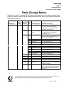
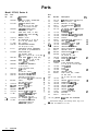
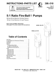
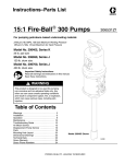
Parts
3X8–448
Rev. F
Supersedes Rev. C
Includes Rev. D and E changes
Parts Change Notice
Some parts in Rev. C of manual 308–448 have changed but have not yet been changed in the
instruction manual. Please note the changes below and mark them in your manual or keep this
sheet with your manual.
Assembly No.
Series
Letter
Change
Part That
Changed
Ref
No.
Part Description
Description of Change
Model 237–410
–
235–230
1
Husky 307 Pump
Replaced by Part No. D31–331 Husky
307 Pump, acetal with PTFE diaphragm and sst balls and seats. See
manual 308–553 for parts.
217–752
2
G700N Air Spray
Gun
Replaced by Part No. 239–542 Delta
Air Spray Gun, .055” orifice. See
manual 308–742.
224–044
17
Cart
Replaced by Part No. 238–938 Cart,
which includes replaceable items 17a
through 17j, listed below.
17a
Front Bracket
Part No. 191–902. Qty: 1.
17b
Capscrew
Part No. 108–768. Qty: 2.
17c
Flat Washer
Part No. 108–788. Qty: 2.
17d
Keps Nut
Part No. 113–761. Qty: 2.
17e
Warning Label
Part No. 290–331. Qty: 1.
17f
Wheel
Part No. 106–062. Qty: 2.
17g
Hub
Part No. 104–811. Qty: 2.
17h
Retaining Ring
Part No. 101–242. Qty: 2.
17j
Tube Plug
Part No. 112–853. Qty: 2.
100–021
36
Capscrew
Change quantity to 4.
100–015
37
Nut
Change quantity to 4.
100–016
38
Lockwasher
Change quantity to 4.
208–536
42
Quick Disconnect
Change to Part No. 114–558.
169–797
56
Nipple
Replaced by Part No. 191–872 Nipple,
1/4 npsm x 1/8 npt.
Added
67
Swivel
Add Part No. 157–705 Swivel, 1/4
npt(m) x 3/8 npsm(f), located between
the fluid whip hose and the gun fluid
inlet. Qty: 1.
All written and visual data contained in this document reflects the latest product information available at the
time of publication. Graco reserves the right to make changes at any time without notice.
June 10, 1998
Table of Contents
Warnings . . . . . . . . . . . . . . . . . . . . . . . . . . . . . . . . . . . . . .
Setup.. . . . . . . . . . . . . . . . . . . . . . . . . . . . . . . . . . . . . . . .
System Component Information . . . . . . . . . . . . . . . . . .
Operation . . . . . . . . . . . . . . . . . . . . . . . . . . . . . . . . . . . . .
Flushing . . . . . . . . . . . . . . . . . . . . . . . . . . . . . . . . . . . . .
Parts . . . . . . . . . . . . . . . . . . . . . . . . . . . . . . . . . . . . . . . .
Technical Data . . . . . . . . . . . . . . . . . . . . . . . . . . . . . . . .
Warranty.. . . . . . . . . . . . . . . . . . . . . . . . . . . . . . . . . . . .
Grace Phone Number . . . . . . . . . . . . . . . . . . . . . . . . . .
Symbols
2
4
6
8
IO
12
16
16
16
Warning
Symbol
This symbol alerts you to the possibility of serious
injury or death if you do not follow the instructions.
Caution Symbol
A
CAUTION
This symbol alerts you to the possibility of damage to
or destruction of equipment if you do not follow the
instructions.
PRESSURIZED FLUID HAZARD
Spray from the gun, hose leaks, or ruptured components can splash fluid in the eyes or on the skin
and cause serious injury.
l
Do not stop or deflect fluid leaks with your hand, body, glove, or rag.
l
Follow the Pressure relief procedure on page 8 before cleaning, checking, or servicing the
equipment.
l
Tighten ail fluid connections before each use.
l
Check the hoses, tubes, and couplings daily. Replace parts immediately if worn, damaged or
loose. Permanently coupled hoses cannot be repaired.
l
Handle and route hoses and tubes carefully. Keep the hoses and tubes away from moving parts
and hot surfaces. Do not use the hoses to pull equipment. Do not expose Grace hoses to temperatures above 18Q°F
(82°C) or below -40°F (-40°C).
m
FiRE AND EXPLOSION HAZARD
Improper grounding, poor air ventilation, open flames, or sparks can cause a hazardous condition
and result in a fire or explosion and serious injury.
2
l
Ground the equipment and the object being sprayed. See Grounding the System on page 5.
l
If there is any static sparking while using the equipment, stop spraying immediately. Identify
and correct the problem.
l
Provide fresh air ventilation to avoid the buildup of flammable vapors from the solvent or the fluid
being sprayed.
l
Do not smoke in the spray area.
l
Extinguish all open flames or pilot lights in the spray area.
l
Do not turn on or off any light switch in the spray area.
l
Electrically disconnect ail equtpment in the spray area.
l
Keep the spray area free of debris, including soivent, rags, and gasoline.
l
Do not operate a gasoline engine in the spray area.
308-448
.
EQUIPMENT MISUSE HAZARD
Equipment misuse can cause the equipment to rupture, malfunction, or start unexpectedly and result
in serious injury.
0
This equipment is for professional use only.
0
Read all instruction manuals, tags, and labels before operating the equipment.
l
Use the equipment only for its intended purpose. If you are in doubt about this, call your Grace
distributor.
0
Do not alter or modify this equipment. Use only genuine Grace parts and accessories.
0
Check equipment daily. Repair or replace worn or damaged parts immediately.
0
Do not exceed the 100 psi (6.9 bar) maximum working pressure at 100 psi (6.9 bar) maximum incoming air pressure of the package or the maximum working pressure of any accessory used with it.
0
Do not move or lift pressurized equipment.
0
Use fluids or solvents that are compatible with equipment wetted parts. See the Technical Data
section of all equipment manuals. Read the fluid and solvent manufacturer’s warnings.
0
Fluid hoses must have spring guards on both ends to protect them from rupture caused by kinks
or bends at or close to the couplings.
0
Comply with all applicable local, state, and national fire, electrical, and other safety regulations.
TOXIC FLUID HAZARD
Improper handling of hazardous fluids or inhaling toxic fumes can cause extremely serious injury or
death from splashing in the eyes, ingestion, or bodily contamination.
l
Know the specific hazards of the fluid you are using.
l
Store hazardous fluid in an approved container. Dispose hazardous fluid according to all local,
state, and-national guidelines.
l
Wear appropriate clothing, gloves, eyewear, and respirator.
l
If the pump diaphragm fails, hazardous fluid may be exhausted along with the air. See your separate pump manual for further information.
.
308-448
3
A
CAUTION
This equipment is compatible with most water
based materials. See the wetted parts in the Technical Data section and your fluid and solvent
manufacturer’s compatibility information.
2.
Clear obstacles and debris that could cause an
unsafe operating environment.
3.
Bring an air line from your compressed air supply
to the pump location. Be sure the air is dry and
filtered. Install a bleed-type master air valve
upstream from the pump. When it is closed and
the pump air regulator (6a) is opened, the bleedtype master air valve relieves all air pressure to the
system components.
4.
Ventilate the spray booth.
Do not use catalyzed materials in heated applications.
I.
Preparing the Operator
All persons who operate the system should be trained
in the safe, efficient operation of all system components as well as the proper handling of the chemical
coating. At a minimum, all operators should thoroughly
read the safety, installation, and operation sections of
this manual and the component manuals.
II.
1.
Preparing the Site
Use at least a 5 HP (3.7 Kw) air compressor for
efficient operation.
To prevent hazardous concentrations of toxic and/
or flammable vapors, spray only in a properly ventilated spray booth. Never operate the spray gun
~unless ventilation fans are operating.
Check and follow all of the national, state, and local
codes regarding air exhaust velocity requirements.
KEY
Components you must supply:
A
B
C
D
E
Bleed-type master air valve
Required for pump; order part no.
11 O-223, l/4” nptQ
Air filter.
Order part no. 11 O-l 46, l/4 npt(f)
Air supply line
Grounded 5 gallon metal pail
Air line moisture trap
/’
--
Components supplied with package:
1
2
3
6a
6b
10
13
42
.
43
44
45
48
54a
54b
58
Husky 307 pump
G700N air spray gun
Fluid heater
Pump air regulator
Gun air regulator
Whip hose
Drain hose
l/4” female quick
disconnect coupler
Pump ground wire
Fluid regulator
Fluid filter
Filter drain valve
Gun fluid hoses
Gun air hose
Tie strap
Fig. 1
4
308-448
I-
III.
Unpacking the System
In addition to the assembled unit, these components
are packed loosely or separately: suction assembly,
hose set, gun, instruction manuals. These are the
manuals you should receive:
308-I 94
307-452
308-325
307-805
307-273
IV.
Husky 307 pump
Air spray gun
Fluid regulator
Fluid heater
Fluid filter
3.
Connect the whip hose (10) to the fluid inlet of the
spray gun (2).
4.
Verify that all fittings throughout the system are
tightened securely.
5.
Use a tie strap (58) to secure the hose set to the
leg of the cart. This provides strain relief so that
tugs on the heavy hoses don’t damage the hose
connections.
v.
Connecting the Hose Set and Gun to
the System See Fig. I.
1
To fluid filter (45) outlet
A
2
A
To gun air regulator (6b) outlet
3
A
To needle valve (5) adapter (25)
To reduce the risk of static sparking, ground the
pump and all other equipment used or located in
the spray area. Check your local electrical code for
detailed grounding instructions for your area and
type of equipment. Ground all of this equipment.
Also read FIRE OR EXPLOSION HAZARD on
page 2.
1.
Pump: One end of the ground wire (43) is already
connected to the pump grounding strip. Connect
the clamp end of the ground wire to a true earth
ground.
2.
Heater: Plug into a properly grounded electrical
outlet. If you use an extension cord, be sure it is a
3-wire grounded cord that is properly sized for the
heater.
3.
Air compressor. Follow manufacturer’s
recommendations.
Fig. 2
1.
2.
Grounding the System
Connect the air hose (54b) between the gun air
regulator (6b) and the air inlet of the spray gun (2).
This is a WI-18 swivel fitting.
Connect one fluid hose (54b) to the fluid filter (45)
outlet. Connect the other fluid hose (54b) to the
needle valve (5) adapter (25). The hose has a
1/4-l 8 swivel fitting.
.
4.
Object being sprayed: Follow local code.
5.
Fluid supply container: Follow local code.
6.
All solvent pails: Follow local code. Use only metal
pails, which are conductive. Do not place the pail
on a non-conductive surface, such as paper or
cardboard, which interrupts the grounding continuity.
308-448
5
System Component Information
VI.
Using the G700N Air Spray Gun
Refer to Fig. 3.
1.
Make initial fluid and air adjustments at the pump
for maximum efficiency.
2.
If you make adjustments at the gun, take noted of
what you do. Then, if the results are not satisfactory, you can easily return the gun to its previous
adjustment. Steps 3 and 4 explain the gun adjustments.
3.
Fan pattern adjusting valve (E). Normal adjustment is the valve turned out fully clockwise and
then turned IN two full turns.
4.
5.
counterclockwise to widen spray pattern.
a.
Turn
b.
Turn clockwise to narrow spray pattern.
Fluid adjusting valve (F). This valve is used in systems that do not have a fluid regulator. For this
system, use the fluid regulator to adjust fluid flow.
The gun has a built-in lead and lag operation.
When triggered, the gun emits air before the fluid
is discharged. When the trigger is released, the
fluid stops before the air flow stops. This helps assure the spray is atomized and prevents fluid buildup on the air cap.
Fig. 3
Air cap horns shown horizonta
which produces a vertical
spray pattern
Air cap horns shown vertical
which produces a horizontal
spray pattern
Fig. 4
6.
7.
6
Loosen the air cap retaining ring (G), and rotate
the horns of the air cap to obtain the desired spray
position. Tighten the retaining ring snugly, but do
not over-tighten. See Fig. 4 for how to obtain a vertical or horizontal spray pattern.
Clean and lubricate the gun as instructed in the
separate gun manual, 307-452.
308-448
VII. Using the Fluid Heater
See Fig. 6.
The heater (3) used in this system is a high mass
heater. Always circulate the fluid when the heater is
operating to prevent overheating and damaging the
fluid. Do not use catalyzed material in this heater.
System Component Information
VIII. Using the Air Regulators and Needle
Always open air and fluid regulators slowly to prevent surging during startup.
The air regulator (6a) on the right side of the pump
controls air to the pump, and the regulator (6b) on
the left side controls air to the gun.
2.
To open the air regulator, pull out the adjusting
knob. Turn the knob IN (clockwise) to open, and
turn the knob fully OUT (counterclockwise) to
close. You may push the adjusting knob in to lock
the adjustment.
3.
The fluid regulator (44) controls fluid from the
pump to the gun. For an accurate setting, adjust
the fluid regulator only when the gun is triggered,
and fluid is flowing through the regulator. Be sure
the jam nut (H) under the T-handle does not interfere with your adjustments. Tighten the jam nut to
lock in the setting, if desired.
4.
To open the fluid regulator, which allows fluid to
flow, turn the T-handle IN (clockwise).
5.
The needle valve (5), located on the fluid return
side of the circulating system, acts as a flow control. Use it to balance the pressure of the circulating fluid so that the pump circulates a sufficient
volume of fluid without running too fast or too slow.
Trigger the gun while adjusting the needle valve.
Turn the needle valve handle IN (clockwise) to
restrict fluid and slow down the pump. Turn the
needle valve handle OUT (counterclockwise) to
allow more flow, which. speeds up the pump.
-
A
Using the 3-Way Valve
See Fig. 6.
valve See Fig. 5.
1.
IX.
Heated systems require that the fluid circulate
constantly when the heater is turned on. The 3-way
valve (9) supplied with this system enables you to
drain or circulate the fluid. The words Drain and Circulate are marked on the valve.
In the Drain position, and with the gun untriggered,
the fluid returns from the gun, to the needle valve
(5), to the hose (12), and to the 3-way valve, which
directs the fluid out the drain hose (13). This position is used when flushing the system and when
relieving system pressure.
In the Circulate position, with the gun untriggered,
fluid returns from the gun, to the needle valve (5),
to the hose (12), and to the 3-way valve, which
directs the fluid back into the pump intake. This
position is used during normal operation, and it
helps keep the fluid at a constant temperature.
CAUTION
Never close the needle valve completely. Doing so
prevents circulation, which can cause the fluid to
overheat, damaging the fluid and the heater.
.6b
A
1
Not visible in this view
Fig. 5
308-448
7
Operation
I.
Pressure Relief Procedure
The system remains pressurized until pressure is
manually relieved. To reduce the risk of serious
injury from pressurized fluid, accidental spray from
the gun, or splashing of any fluid, follow this procedure whenever you
Are instructed to relieve pressure
Stop spraying
Check or service any system equipment
Install, clean, or change spray nozzles
l
l
l
l
1.
Be sure the pump air regulator (6a) is still open.
Close the master air valve (A) to relieve pump air
.
pressure.
2.
Close both air regulators (6a,6b).
3.
Turn the 3-way valve (9) to Drain.
4.
Trigger the spray gun into a waste pail to relieve
fluid pressure.
5.
Turn off and unplug the heater (3).
Flush the Pump Before First Use
II.
Flush with a solvent compatible to your fluid. Consult
the fluid manufacturer’s literature for recommendations. See Flushing on page IO.
Priming the System
III.
See Fig. 7.
1.
Put the suction tube (15) in the prepared fluid.
2.
Hook the drain hose (13) on the waste pail.
3.
Close the filter drain valve (48).
4.
Turn the 3-way valve (9) to Drain.
5.
Open the fluid pressure regulator (44) (fully
clockwise).
6.
Turn the needle valve (5) ail the way out
(counterclockwise)
7.
Close the gun and pump air regulators (6a,6b) (full
counterclockwise).
8.
Connect the air line (C) to the pump.
9.
Open the master air valves (A).
10. Slowly raise the pump air regulator (6a) pressure
to 20 to 30 psi (1.4 to 2.1 bar). The pump will cycle
quickly until is it primed. When it is primed, the
pump will stall against pressure. Now set the pump
air pressure to 40 psi (2.8 bar). When fluid flows
from the drain hose, turn the 3-way valve to Circulate.
11. Hold the gun against and aimed into a grounded
metal waste pail. Trigger the gun, and slowly open
the fluid regulator (44). The gun will emit air until
the fluid arrives. When fluid flows freely, release
the gun trigger.
KEY
A
C
3
6a
6b
9
13
44’
48
Bleed-type master air valve
Air line
fluid heater
Pump air regulator
Gun air regulator
3-way valve
Drain hose
Fluid regulator
Filter drain valve
Fig. 7
308-448
a
-
04015
.
Operation
12. Adjust the needle valve to set the pump cycle rate
at 1 stroke every 15 seconds.
13. Turn the heater dial to 3. Whenever the heater setting is changed, allow the fluid to circulate and stabilize before checking the temperature (about IO
minutes) .
A
Fluid Viscosity
Fluid Droop A
Measured with #2 Zahn cup
Light (18-25 seconds)
Medium (25-40 seconds)
Heavy (40-60 seconds)
8-10” (200-250 mm)
6-8” (150-200 mm)
4-6” (100-l 50 mm)
CAUTION
Be sure the fluid is circulating whenever the heater
is on to reduce the risk of damage to the fluid or
the heater.
03998
3.
Be sure the gun’s fan pattern adjusting valve (E)
has been turned OUT fully clockwise and then
turned IN two full turns. See Fig. 9.
4.
Release the trigger. Install the air cap.
5.
Partially trigger the gun so only air is emitted. Set the
gun air regulator (6b) pressure to 60 psi (4.2 bar)70
psi (4.9 bar).
.
6.
Spray a stationary test pattern on scrap paper.
Hold the gun 10 to 12 in. (250 to 300 mm) from the
paper, and spray for 2 or 3 seconds. If the spray
pattern is poorly atomized, you may need to adjust
the air or fluid pressure.
14. Follow the fluid manufacturer’s recommendations
for temperature, and adjust the heater accordingly.
If unknown, set the temperature to 110°F (43°C)
at the outlet thermometer. Do not proceed until the
temperature has stabilized. Do not allow the fluid
to exceed 140°F (60°C) unless your fluid
manufacturer recommends higher temperatures.
15. Spray fluid into a waste pail for about 10 seconds
to bring heated material to the gun.
16. Hook the drain hose (13) on the fluid supply pail.
IV.
1.
.
2.
Setting Fiuid and Air Pressure
With the system primed, the gun regulator (6b)
closed, and the pump air regulator (6a) set as
instructed in Step 10 on page 8, adjust the fluid
pressure regulator (44) to the fluid manufacturer’s
specifications, if available. Otherwise, follow Step
2 to determine the fluid pressure setting.
To determine the fluid pressure setting, hold the
gun parallel to the floor. (Be sure to catch the fluid
in a container.) With the gun air pressure turned
OFF, trigger the gun. Adjust the fluid pressure regulator (4) until the straight fluid stream is within the
range indicated for the viscosity of your fluid before
it drops off. See Fig. 8. Make note of the pressure
on the fluid gauge it is your optimal fluid pressure
setting.
If the spray pattern atomization is not fine enough,
increase the gun air pressure. If the spray pattern
atomization is too fine, decrease the gun air pressure. If the atomization is still not good enough, try
lowering the fluid pressure in increments of 2 or 3
psi to achieve the desired finish quality.
NOTE: For the most efficient paint usage, use the
lowest air pressure needed to obtain a good finish.
Higher air pressures create more overspray and
uses more fluid.
7.
Adjust the fan pattern adjusting valve (E) to fine
tune the spray pattern. Turn counterclockwise to
widen spray pattern. Turn clockwise to narrow
spray pattern. See Fig. 9.
308-448
9
Operation
v.
Production
Spraying
VI.
You are now ready for production spraying. If you stop
spraying for more than 30 minutes, turn off the heater
to prevent overheating the fluid.
Shutting Down the System
Shut down the system at the end of the work shift and
before checking, adjusting, cleaning, or repairing the
system. Always follow the Pressure Reiief Procedure
on page 8.
Flushing
When to Flush
Before the first use
When changing colors
4.
Hook the drain hose (13) on the waste pail.
5.
Turn the 3-way valve (9) to Drain.
6.
Turn the needle valve (5) all the way out
(counterclockwise).
7.
Put the suction tube (15) in a grounded pail with
about 1 gallon (4 liter) of a compatible solvent.
8.
Make sure the air regulators (6a,6b) and master air
valves (A) are closed.
Before fluid can dry or settle out in a dormant
system
Before storing the system
II.
How to Flush
See Fig. 10.
NOTE: The gun air regulator (6b) always stays closed
during flushing.
you flush, be sure the heater is turned off
and the fluid has cooled. This is to reduce the risk
of a fire or explosion and serious injury.
9.
Make sure the fluid regulator (44) is open (turned
in) to allow fluid flow.
10. Connect the air line (C) to the pump.
1.
Turn off the heater (3), and allow the system to
cool.
2.
Remove the air cap from the gun, and clean separately. Do not reinstall at this time.
3.
10
Open the filter drain valve (48). Unscrew the fluid
filter (45) bowl. Remove the screen. See manual
‘307-273. Reinstall the bowl without the screen.
308-448
11. Open the master air valves (A).
12. Slowly open the pump air regulator (6b) until the
pump starts.
13. Hold the gun against a grounded metal waste pail.
Trigger the gun slowly. The gun will emit air until
the fluid arrives. When solvent appears, release
the trigger.
.
Flushina+a
14. For a first-time flush, trigger the gun, and circulate
the solvent for 20 seconds.
For flushina after soravina fluid, turn the 3-way
valve to Circulate. Trigger the gun periodically
whiie circulating the solvent. Periodically turn the
3-way valve to Drain to flush out some dirty solvent. Flush until the system is clean. Repeat with
clean solvent, if necessary.
15. Raise the suction tube out of the solvent, trigger
the gun, and run the pump until air comes from the
gun. Turn the 3-way valve to Drain, and run the
pump until all air is expelled.
16. Release the trigger, and close the fluid regulator
(44) and the air regulators (6a,6b).
17. Clean the filter screen, air cap, and fluid nozzle
separately.
18. Open the filter drain valve (48). Remove the filter
bowl, and reinstall the filter screen.
19. Thoroughly clean the inside and outside of the
suction tube.
20. You are now ready to prime the system with
another fluid or to store the system.
KEY
A
C
3
6a
6b
9
13
44
45
48
Bleed-type master air valve
Air line
Fluid heater
Pump air regulator
Gun air regulator
3-way valve
Drain hose
Fluid regulator
Fluid filter
Filter drain valve
Fig. 10
c --
308-448 1 1
Parts
Model 237410, Series A
Ref
No.
Part
No.
1
235-230
2
217-752
3
220-522
4
110-160
5
6
108-233
111-804
7
8
11 O-209
108-l 90
9
214-711
10
214-699
11
205-l 69
12
206-966
13
206-965
14
188-l 73
15
16
165-767
188-l 07
17
224-044
18
19
156-849
188-077
20
21
22
803-088
162-453
111-807
23 _
24
158-683
112-408
12
308-448
Description
QW
HUSKY 307 PUMP, Acetal/PTFE
See 308-l 94 for parts
G700N AIR SPRAY GUN
with 106-706 air cap and O/ON
needle, see manual 307-452
VISCON2 HEATER (120V)
See 307-805 for parts
CORD ASSY, heater, 12 AWG,
SOOV, 20 AMP, 105°C (221 OF),
6.5’ (2 m) long
NEEDLE VALVE
AIR REGULATOR, 0 to 125 psi
(0 to 8.5 bar) pressure range
NUT, regulator
AIR PRESSURE GAUGE,
0 to 100 psi (0 to 7 bar)
3-WAY BALL VALVE, l/4 npt(m),
See 306-861 for parts
WHIP HOSE,cpld
l/4 npsm(fbe) swivel,
3/l 6” ID x 6’ (4.8 mm ID x 1.8 m) long
FLUID HOSE, 3/8” npt, spring (fbe)
guards both ends, 3’ (0.9 m) long
HOSE, l/4-1 8 npsm(fbe)
1.5’ (.45 m) long
DRAIN HOSE ASSEMBLY
3’ (0.9 m) long
FLUID SUCTION HOSE,
3/4” ID x 3.5’
(19 mm ID x 1.06 m)
SUCTION TUBE, 3/4 npt(f)
AIR INLET TUBE,
0.25” OD x 0.170” ID x 6”
(6.3 mm OD x 4.3-mm ID x 152 mm)
CART
See 308-l 36 for parts
NIPPLE, 3/8-18 npt
NIPPLE, l/4-18 npt x
l/4-8.6 sf, cst
TEE
NIPPLE, l/4 npt x l/4 npsm
90” TUBE Fll-TlNG ELBOW,
l/4 npt(m) x ferrule nut for
0.25” (6.3 mm) OD tube
9 0 ” ELBOW, l/2 npt (m x f)
90” CORD GRIP ELBOW,
l/2 npt(m), includes nut,
washer, and grommet
1
1
Ref.
No.
Part No.
Description
25
26
28
29
30
31
100-840
111-805
188-093
169-971
103-473
155-494
32
33
34
35
36
37
38
4u
41
42
43
44
45
101-754
107-219
100-639
108-290
100-021
100-015
100-016
187-732
188-l 74
208-536
222-011
236-216
218-029
46
47
48
49
100-l 76
11 O-249
210-658
176455
50
51
52
53
54
54a
54b
55
56
57
58
60
61
62
63
64
66
104-984
156-953
100-509
223-324
237494
90” ELBOW, street, l/4 npt (m x f)
BLOCK, diverter
BRACKET, air regulator
AIR LINE FITTING, 3/8 npt(m)
STRAP
90” SWIVEL UNION, 3/8 npsm(f) x
3/8 npt(m) swivel
PLUG, pipe, 3/8 npt
BUSHING, 3/4 npt(m) x l/2 npt(f)
WASHER, wrought, l/4”
SCREW
CAPSCREW, l/4-20 uric-2a x 1”
NUT, l/4-20 uric-2a
LOCKWASHER, spring, l/4”
WARNING LABEL
IDENTIFICATION LABEL
QUICK DISCONNECT, femaleGROUND WIRE
REGULATOR; l/4 n npt x 3
FLUID FILTER
see 307-273 for parts
BUSHING, 3/8 to l/4 npt
ELBOW, l/4 npt mbe
BALL VALVE
FLUID PRESSURE GAUGE
0 to 100 psi (0 to 6.9 bar) range
TEE, l/4 npt(f)
STUD
PLUG, l/4”
GROUND WIRE
FLUID HOSE SET, includes:
two fluid hoses,
one air hose and hose insulator
NUT
NIPPLE, l/4 npsm x l/8 npt
MANIFOLD, l/8 npt(f)
PLUG, hex socket, l/8 npt
NIPPLE; 3/8” x l/2”
SCREW
NIPPLE; l/4” x 3/8”
CONNECTOR, male .
BUSHING
NIPPLE, short
1
1
1
2
2
2
1
1
1
1
1
1
1
1
100-307
169-797
169-795
100-l 39
159-239
102-790
165-l 98
111-864
100-505
156-971
Use only genuine Grace
parts and accessories.
A Replacement Danger and Warning labels, tags, and
cards are available at no cost.
my.
Parts
16’
Model 237410, Series A
25
60
23
/
308-448 13
Notes
.
14
308-448
Notes
c
308-448
15
Manual Change Summary
Technical Data
Maximum fluid working pressure . . . . . . . . . . 100 psi (6.9 bar)
Maximum incoming air pressure . . . . . . . . . . 100 psi (6.9 bar)
Gun air consumption1 6 scfm at 50 psi (0.45 m3/min at 3.5 bar)
Pump air consumption . . . . . . . . at I/Z gpm: 1 scfm at 60 psi
(0.028 m3/min at 4.2 bar)
at free flow: 5.5 scfm (0.15 m3/min)
Heater electrical requirement . . . . . . . . . . 2000 Watts, 110 V,
16.7 Amp
Wetted parts
Pump* . acetal with conductive SST fibers, acetal, PTFE
Spray gun . . . . . . . . . . . . . . . . . . . . . 303/420 stainless steel
Fluid heater. . . . . . . . . . . . . . . . . . . . . . . . 304 stainless steel
Fluid hose and tubing . . . . . , . . . . . . . . . . . . . . . . , . . . . nylon
Fluid fittings . acetal, 304/316
stainless steel, carbon steel
Fluid regulator . . . . acetal resins, PTFE, tungsten carbide,
304/316/l 7-4 pH stainless steel
Fluid filter . . . . . . . . . . . . . . aluminum, carbon steel, PTFE,
304/316
stainless steel, polyethylene
l
The current revision of this manual includes the
following changes:
Page 12, Parts List:
l
The quantity of item 25 (elbow) is changed to 3.
l
The quantity of item 47 (elbow) is changed to 1.
Page 13, Parts Drawing:
l
Item 60 is changed to 62, and item 62 is changed
to 60.
l
The l/4-in. male elbow (47) under the regulator (44)
is replaced with a l/4-in. m x f street elbow (25) and
a short nipple (66).
Acetal is not recommended for use with acid-catalyzed materials.
All 304, 316, and 17-4 pH stainless steels are electropolished
passivated.
Teflofl
and/or
is a registered trademark of the DuPont Co.
The -Grace Warranty and Disclaimers
WARRANTY
Grace warrants all equipment manufactured by it and bearing its name to be free from defects in
the date of sale by an authorized Grace distributor to the original purchaser for use. As purchaser’s
warranty, Grace will, for a period of twelve months from the date of sale, repair or replace any part
defective. This warranty applies only when the equipment is installed, operated and maintained in
written recommendations.
material and workmanship on
sole remedy for breach of this
of the equipment proven
accordance with Grace’s
This warranty does not cover, and Grace shall not be liable for, any malfunction, damage or wear caused by faulty installation,
misapplication, abrasion, corrosion, inadequate or improper maintenance, negligence, accident, tamperfng, or substitution of
non-Grace component parts. Nor shall Grace be liable for malfunction, damage or wear caused by the incompatibility with Grace
equipment of structures, accessories, equipment or materiais not supplied by Grace, or the improper design, manufacture,
installation, operation or maintenance of structures, accessories, equipment or materials not supplied by Grace.
This warranty is conditioned upon the prepaid return of the equipment claimed to be defective to an authorized Grace distributor
for verification of the claim. If the claimed defect is verified, Grace will repair or replace free of charge any defective parts. The
equipment will be returned to the original.purchaser
transportation prepaid. If inspection of the equipment does not disclose any
defect in material or workmanship, repai’rs will be made at a reasonable charge, which charges may include the costs of parts,
labor and transportation.
DISCLAIMERS AND LIMITATIONS
The terms of this warranty constitute purchaser’s sole and exclusive remedy and are in lieu of any other warranties (express or
implied), including warranty of merchantability or warranty of fitness for a particular purpose, and of any non-contractual
liabilities, including product liabilities, based on negligence or strict liability. Every form of liability for direct, special or
consequential damages or loss is expressly excluded and denied. In no case shall Grace’s liability exceed the amount of the
purchase price. Any action for breach of warranty must be brought within two (2) years of the date of sale.
EQUIPMENT NOT COVERED BY GRACO WARRANTY
Grace makes no warranty, and disclaims all implied warranties of merchantability and fitness for a particular purpose, with
respect to accessories, equipment, materials, or components sold but not manufactured by Grace. These items sold, but not
manufactured by Grace (such as electric motor, switches, hose, etc.) are subject to the warranty, if any, of their manufacturer.
Grace will provide purchaser with reasonable assistance in making any claim for breach of these warranties.
Grace Phone Number
TO PLACE AN ORDER, contact your Grace
l-800-367-4023 Toll Free
Foreign
Offices:
Belgium,
distributor, or call this number to identify the distributor closest to you:
Sales Offices: Atlanta, Chicago, Detroit, Los Angeles
Canada, England, Korea, Switzerland, France, Germany,
Hong
Kong,
GRACO INC. P.O. BOX 1441 MINNEAPOLIS, MN 55440-1441
PRINTED IN U.S.A.
16
308-448
308-448 September 1994, Revised December 1995
Japan
I