1
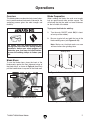
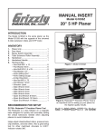
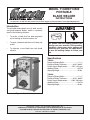
MODEL T10499/T10500
PORTABLE
BLADE WELDER
INSTRUCTIONS
For questions or help with this product contact Tech Support at (570) 546-9663 or [email protected]
Introduction
This portable blade welder can cut, weld, anneal,
and grind bandsaw blades, which is commonly
done in the following situations:
•To re-join a blade that has been purposely
cut for making an internal contour cut.
•To repair a broken blade that is still sharp and
useful.
•To fabricate a new blade from bulk blade
material.
Hot sparks from the welding process can
damage your eyes and skin. During welding
operations, always wear safety goggles and
protective gear, and keep the spark deflector over the welding clamps to reduce your
risk.
Specifications
T10499:
Range of Blade Widths............................. 1⁄ 8" –1⁄ 2"
Range of Blade Thickness...............0.02"–0.035"
Power Supply Requirement...........115V, 15 Amps
Welding Power........................................ 1.2 KVA
Shipping Weight.........................................50 lbs.
T10500:
Range of Blade Widths............................. 3 ⁄ 8" –3 ⁄4"
Range of Blade Thickness...............0.02"–0.035"
Power Supply Requirement..........230V, 20 Amps
Welding Power........................................ 4.2 KVA
Shipping Weight.........................................69 lbs.
Figure 1. Blade Welder.
Copyright © APRIL, 2012 By Grizzly Industrial, Inc.
Warning: No portion of this manual may be reproduced in any shape
Or form without the written approval of Grizzly Industrial, inc.
#TS14909 printed in TAIWAN
Identification
Welding
Button
Anneal
Button
Anneal
Strength
Switch
Clamp
Pressure
Switch
Main
ON/OFF
Switch
Blade
Shear
Carrying
Handle
(1 of 2)
Clamping
Jaws
Spark
Deflector
Grinder
Switch
Grinding
Wheel
Figure 2. Identification.
To reduce the risk of
serious injury when using
this machine, read and
understand this entire
manual before beginning
any operations.
-2-
T10499/T10500 Blade Welder
Safety for Blade Welders
WELDING FUMES. Breathing welding fumes can
cause respiratory damage. Maintain adequate ventilation during and after welding operations.
PREVENT FIRES. Welding work zones must be
kept clear of flammable liquids or gases, such as
gasoline or solvents, and combustible solids, such
as paper or wood. Provide approved fire extinguishing equipment for the welding zone. Stay
alert for sparks and spatter thrown into cracks and
crevices that can start a smoldering fire.
PERSONAL PROTECTIVE EQUIPMENT. Wear
eye and body protection approved for welding
operations, such as safety goggles, clean and
oil-free protective clothing, leather gloves, long
sleeves, and cuffless pants. Protect other people
and property in the welding work zone from exposure to sparks and hot spatter.
ABRASION INJURIES. The grinding wheel can
remove skin very quickly. Always keep your fingers
and hands away from the spinning grinding wheel
to reduce this risk.
ELECTRIC & MAGNETIC FIELDS (EMF). Welding
operations create EMF around the welding equipment and workpieces. Workers who have pacemakers must consult with their physician before
using this equipment or stay at least 50 feet from
welding operations.
EQUIPMENT MAINTENANCE. Make sure equipment inspections and maintenance are performed
by a qualified person. Stop the welding operation
and disconnect the welder from power if the equipment is damaged or malfunctions.
STABLE WORK SURFACE. If the welder unexpectedly moves during operation, burn, laceration,
or abrasion injuries could occur. Always make sure
the welder is mounted on a stable and lever surface before operations.
BLADE BREAKAGE. Blades that are not welded
correctly can break under the stresses of using
them on the bandsaw. Have only one weld on a
blade. Always inspect the weld as instructed. Make
sure the annealing and grinding process does not
compromise the integrity of the weld. If you have
any doubt about weld quality, start again.
If you have never used this type of welder before, We strongly recommend that you read
books, trade magazines, or get formal training before beginning any projects. Regardless of the
content in this section, Grizzly Industrial will not be held liable for accidents caused by lack of
training.
T10499/T10500 Blade Welder
-3-
Power Supply
Full-Load Current Rating
The full-load current rating is the amperage a
machine draws at 100% of the rated output power.
On machines with multiple motors, this is the
amperage drawn by the largest motor or sum of all
motors and electrical devices that might operate
at one time during normal operations.
T10499 Full-Load Current Rating......... 8 Amps
T10500 Full-Load Current Rating...... 20 Amps
The full-load current is not the maximum amount
of amps that the machine will draw. If the machine
is overloaded, it will draw additional amps beyond
the full-load rating.
If the machine is overloaded for a sufficient length
of time, damage, overheating, or fire may result—
especially if connected to an undersized circuit.
To reduce the risk of these hazards, avoid overloading the machine during operation and make
sure it is connected to a power supply circuit that
meets the requirements in the following section.
Electrocution, fire, or
equipment damage may
occur if machine is not
correctly grounded and
connected to the power
supply.
Circuit Information
A power supply circuit includes all electrical
equipment between the breaker box or fuse panel
in the building and the machine. The power supply circuit used for this machine must be sized to
safely handle the full-load current drawn from the
machine for an extended period of time. (If this
machine is connected to a circuit protected by
fuses, use a time delay fuse marked D.)
-4-
Note: The circuit requirements listed in this manual apply to a dedicated circuit—where only one
machine will be running at a time. If this machine
will be connected to a shared circuit where multiple machines will be running at the same time,
consult a qualified electrician to ensure that the
circuit is properly sized for safe operation.
Grounding Requirements
This machine MUST be grounded. In the event
of certain malfunctions or breakdowns, grounding
reduces the risk of electric shock by providing a
path of least resistance for electric current.
Improper connection of the equipment-grounding
wire can result in a risk of electric shock. The
wire with green insulation (with or without yellow
stripes) is the equipment-grounding wire. If repair
or replacement of the power cord or plug is necessary, do not connect the equipment-grounding
wire to a live (current carrying) terminal.
Check with a qualified electrician or service personnel if you do not understand these grounding
requirements, or if you are in doubt about whether
the tool is properly grounded. If you ever notice
that a cord or plug is damaged or worn, disconnect it from power, and immediately replace it with
a new one.
For your own safety and protection of
property, consult an electrician if you are
unsure about wiring practices or electrical
codes in your area.
T10499/T10500 Blade Welder
T10499 Circuit Requirements
T10500 Circuit Requirements
This machine is prewired to operate on a 115V
power supply circuit that has a verified ground and
meets the following requirements:
This machine is prewired to operate on a 230V
power supply circuit that has a verified ground and
meets the following requirements:
Nominal Voltage......................................... 115V
Cycle...........................................................60 Hz
Phase............................................ Single-Phase
Power Supply Circuit.......................... 15 Amps
Plug/Receptacle.............................. NEMA 5-15
Nominal Voltage.........................................230V
Cycle...........................................................60 Hz
Phase............................................ Single-Phase
Power Supply Circuit.......................... 20 Amps
Plug/Receptacle.............................. NEMA 6-20
This machine is equipped with a power cord
and plug that have an equipment-grounding wire
and a grounding prong (see Figure 3). The plug
must only be inserted into a matching receptacle
(outlet) that is properly installed and grounded in
accordance with all local codes and ordinances.
The provided power cord and the plug specified
above have an equipment-grounding wire and a
grounding prong. The plug must only be inserted
into a matching receptacle (outlet) that is properly installed and grounded in accordance with all
local codes and ordinances (see Figure 4).
GROUNDED
6-20 RECEPTACLE
GROUNDED
5-15 RECEPTACLE
Current Carrying Prongs
Grounding Prong
5-15 PLUG
Neutral Hot
6-20 PLUG
Grounding Prong
Figure 3. Typical 5-15 plug and receptacle.
Figure 4. Typical 6-20 plug and receptacle.
SHOCK HAZARD!
Two-prong outlets do not meet the grounding
requirements for this machine. Do not modify
or use an adapter on the plug provided—if
it will not fit the outlet, have a qualified
electrician install the proper outlet with a
verified ground.
No adapter should be used with the
required plug. If the plug does not fit the
available receptacle, or the machine must
be reconnected for use on a different type
of circuit, the reconnection must be made
by a qualified electrician and comply with all
local codes and ordinances.
T10499/T10500 Blade Welder
-5-
Extension Cords
We do not recommend using an extension cord
with this machine. If you must use an extension
cord, only use it if absolutely necessary and only
on a temporary basis.
Extension cords cause voltage drop, which may
damage electrical components and shorten motor
life. Voltage drop increases as the extension cord
size gets longer and the gauge size gets smaller
(higher gauge numbers indicate smaller sizes).
Any extension cord used with this machine must
contain a ground wire, match the required plug
and receptacle, and meet the following requirements:
The alignment wings keep the blade straight when
cutting with the shear.
Tools Needed
Qty
Phillips Screwdriver #2....................................... 1
Wrench or Socket 10mm.................................... 1
To attach the blade shear wings:
1.Remove the two Phillips head screws shown
in Figure 6, and the attached hex nuts, and
flat washers.
Note: Keep the spacers that separate the two
plates in place.
T10499 Minimum Gauge Size...............14 AWG
T10500 Minimum Gauge Size...............12 AWG
Maximum Length (Shorter is Better).......25 ft.
Remove these
Screws
Assembly
Except for the blade shear alignment wings (see
Figure 5), the welder is shipped fully assembled.
Figure 6. Phillips head screws to be removed.
2.Use the fasteners removed in Step 1 to
attach the alignment wings in the positions
shown in Figure 7.
Alignment Wings
Figure 5. Blade shear alignment wings.
Figure 7. Alignment wings installed.
-6-
T10499/T10500 Blade Welder
Operations
Overview
This blade welder uses electrical resistance (induction) to weld bandsaw blade ends. Afterwards, the
annealing process gives the weld strength and
flexibility.
Blade Preparation
When welding the blade, the ends must evenly
butt up against each other and be square. This
will ensure the that the weld is of even thickness
for the full width of the blade.
To prepare the blade for welding:
1.Turn the main ON/OFF switch ON (it is located on top of the welder).
2. Be sure to grind off any teeth that are in the
blade welding zone (see Figures 9–10).
Hot sparks from the welding process can
damage your eyes and skin. During welding
operations, always wear safety goggles and
protective gear, and keep the spark deflector over the welding clamps to reduce your
risk.
Note: Make sure the blade ends are even
with each other after grinding them.
Welding Zone
Blade Shear
To use the blade shear, place the back of the
blade evenly against the front alignment wings of
the blade shear, as shown in Figure 8, then firmly
pull the handle down to square off the blade end.
Grind Off
Figure 9. Blade ends and welding zone.
Handle
Blade Shear
Wing
Figure 8. Using the blade shear.
Figure 10. Using the grinder.
T10499/T10500 Blade Welder
-7-
Note: You can make sure that the blade
ends are even with each other by stacking
them together with the teeth facing in opposite directions (see Figure 11), then grinding
them. Regardless of the grinding angle, the
blade ends will match evenly for welding.
3.Rotate the clamp pressure switch
(see Figure 12) to zero. This spreads the
clamps apart to allow proper positioning of
the blade ends.
Welding Clamps
Clamp
Pressure
Switch
Clamp Levers
Figure 12. Clamping controls.
Figure 11. Blade ends stacked with teeth facing
opposite directions.
3. Use 120-grit emery cloth or an equivalent
to lightly sand the part of the blade that will
contact the welder clamps. This helps ensure
a good electrical contact with the blade for
welding.
Note: To prevent dulling the teeth, keep the
emery cloth away from them when sanding
the blade surface.
4. Pull the spark deflector up and loosen the
welding clamps by pulling the clamp levers
down.
5.Position the back of one blade end evenly
against the back of the right welding clamp
so that the end is midway between the two
clamps, as shown in Figure 13.
Blade
End
Welding
1.Turn the main ON/OFF switch OFF, then
DISCONNECT WELDER FROM POWER!
2.Thoroughly clean the welding clamps to
remove debris, oily substances, or flash from
previous welding operations. If necessary,
lightly sand them with 120-grit emery cloth.
Figure 13. Blade end properly position in
welding clamp and locked in place.
6.Rotate the right clamp lever up to secure the
blade end in place.
-8-
T10499/T10500 Blade Welder
7.Place the other blade end in the left welding
clamp and position it so that it evenly butts up
against the opposing blade end, then clamp
it in place by rotating the left clamp lever up
(see Figure 14).
8.Use the tables below to set the clamp pressure switch and the anneal strength (see
Figure 16).
• For T10499:
Blade Width
Clamp
Pressure
Anneal
Strength
⁄ 8"–1⁄4"
1–2
Low
⁄ 8"– ⁄ 2"
3–4+
High
Blade Width
Clamp
Pressure
Anneal
Strength
3
⁄ 8"–1⁄ 2"
1–2
Low
1
⁄ 2"–3 ⁄4"
3–4+
High
1
3
1
• For T10500:
Blade Ends
Figure 14. Blade ends in correct position for
welding.
Note: To ensure a good blade weld, it is
critical that the blade ends are secured in the
welding clamps evenly and with no overlap
(see Figure 15).
Note: As you rotate the clamp pressure
switch, the left clamp will move and apply
pressure toward the right. This pressure is
necessary to maintain contact between the
blade ends as the metal melts during the
welding operation.
Anneal
Strength Switch
Clamp
Pressure Switch
Blade Ends Flat w/No Overlap
Welding
Button
Blade Ends Butt Evenly
Figure 16. Welding controls.
9. Lower the spark deflector over the clamps.
Figure 15. Blade ends correctly secured in
welding clamps.
10.Put on safety goggles and heavy leather
gloves.
11. Connect the welder to power and turn the
main ON/OFF switch ON.
T10499/T10500 Blade Welder
-9-
Hot sparks from the blade welding operation could be thrown in all directions and
cause burns or fire.
When using the blade welder, always keep
the spark deflector over the clamps and
protect yourself from the flying sparks.
Have fire extinguishing equipment readily
available.
16.Inspect the weld. The welded joint should be
even across the width of the blade with no
gaps (see Figure 17).
Correct
Not Correct
DO NOT weld near flammables.
NOTICE
For good metal-to-metal contact between
the welding clamps and the blade, make
sure the blades and the clamps are free
from any debris, coatings, or flash before
and after each use of the welding station.
Before welding a blade back together to perform an internal cut, insulate the entire blade
from the metal surfaces of the bandsaw to
ensure a good flow of current through the
blade.
Not Correct
Figure 17. Blade welding joint examples.
—If the weld is satisfactory, anneal the weld
as instructed in the next subsection.
—If the weld is NOT satisfactory, use the
blade shear to completely remove the weld
and perform the Blade Preparation and
Correct
Welding procedures
again that begin on
Page 7.
12.Press and release—DO NOT hold—the weld
button.
Note: A limit switch senses the electrical
resistance between the blade ends. If there
is an adequate amount of welded material,
the limit switch will not allow the weld button
to activate the operation again.
Not Correct
13. Allow the blade to cool.
14.Rotate the clamp lever switch to zero to
release the clamp pressure.
15. Remove the blade.
-10-
T10499/T10500 Blade Welder
Annealing Weld
When the blade ends are welded, the metal
becomes hard and brittle, which is not suitable
for a bandsaw blade that must continuously bend
smoothly under stress.
To bring the weld strength and flexibility to acceptable levels for a bandsaw blade, the annealing
process re-heats the weld area, then allows it to
cool gradually.
To anneal the weld:
1.Place the blade in the clamps so that the
weld is centered between the clamps.
2.Secure the blade by moving both clamp
levers up.
3. Make sure the anneal strength switch is in
the proper position for the width of the blade
(refer to the charts in Step 8 on Page 9).
4. For Carbon Steel Blades: Rapidly press
and release—DO NOT hold—the anneal button (see Figure 18) until the weld zone turns
a dull red color. Continue pressing the anneal
button with decreasing frequency until the
weld no longer glows.
Anneal
Strength Switch
5. Allow the blade to completely cool.
6.Remove the blade from the clamps.
7.Grind the weld flatCorrect
on both sides so the blade
will run smoothly on the bandsaw wheels.
Note: Make sure not to grind the teeth or
blade body. Do notNot
overheat
the blade during
Correct
grinding—this will weaken the blade.
8. For Bi-Metal Blades Only: Repeat Steps
3–5 (not Step 6).
Not Correct
9.Test the strength and flexibility of the weld
by bending the blade in an arc (with the
weld at the top of the arc) similar in size and
shape of the bandsaw wheels. The blade
should bend smoothly without any angles
(see Figure 19).
Correct
Not Correct
Figure 19. Comparison of correct and incorrect
blade weld bends.
Anneal Button
Figure 18. Annealing controls.
For Bi-Metal Blades: Rapidly press and
release—DO NOT hold—the anneal button until the weld zone starts to glow, then
release the anneal button completely.
T10499/T10500 Blade Welder
—If the blade does show signs of bending or
breaking at the weld, use the blade shear
to completely remove the weld and perform
the Blade Preparation and Welding procedures again that begin on Page 7.
10.Turn the /OFF switch OFF, then DISCONNECT
WELDER FROM POWER!
11.Thoroughly clean the welding clamps to
remove debris, oily substances, or flash from
previous welding operations. If necessary,
lightly sand them with 120-grit emery cloth.
-11-
Troubleshooting
Review the troubleshooting and procedures in this section if a problem develops with your machine. If you
need replacement parts or additional help with a procedure, call our Technical Support at (570) 546-9663.
Note: Please gather the serial number and manufacture date of your machine before calling.
Symptom
Possible Cause
Machine does not
start or a breaker
trips.
1.Plug/receptacle is at fault or wired 1.Test for good contacts; correct the wiring.
incorrectly.
2.Ensure circuit size is suitable for this machine;
2. Wall fuse/circuit breaker is blown/tripped.
replace weak breaker.
3. Main ON/OFF switch turned OFF or is at 3.Ensure main ON/OFF switch is turned ON; replace
switch.
fault.
4. Check for broken wires or disconnected/corroded
4. Wiring is open/has high resistance.
connections, and repair/replace as necessary.
5.Replace weld button.
5. Weld button is at fault.
Weld is mis-aligned. 1.Debris or flash on weld clamps or blade.
2. Blade ends not cut off square.
3. Blade ends not evenly butted in clamps.
4. Clamp pressure not set correctly.
Weld not complete
(has blow-holes)
1. Blade ends not clamped properly.
2. Blade ends not even with each other.
Weld breaks or is
brittle.
1. Weld not correctly annealed.
2. Weld is ground too thin.
3.Debris or oil in weld.
4. Blade overheated during grinding.
-12-
Possible Solution
1.Remove debris, oily substances, or flash from weld
clamps and blade.
2.Use the blade shear to cut blades; grind ends
together (see Note on top of Page 8).
3. Make sure blade ends are evenly butted against each
other before securing with clamp levers (Page 8).
4.Set clamp pressure correctly according to tables on
Page 9.
1. Make sure blade ends are evenly butted against
each other in clamps; use the correct clamp pressure
(Page 8).
2.Use the blade shear to cut blades; grind ends
together (see Note on top of Page 8).
1. Correctly perform the annealing procedure on
Page 11.
2.Only grind flash even with blade body.
3. Make sure clamps and blade ends are clean of
debris, oily substances, and flash.
4.Use light passes with the grinding wheel.
T10499/T10500 Blade Welder
T10499 Wiring Diagram
Main
Power Switch
Anneal
Strength Switch
HY29G
20/15A 277V
Ground
Anneal
Button
Clamp
Pressure
Cam
COM
COM
Defond
Neutral
Welding
Button
Defond
Hot
ENEC
T120/55
NO NC
NO NC
115VAC
NEMA 5-15 Plug/Receptacle
(As Recommended)
Welding
Unit
Defond
NC NO
COM
Ground
1
E
2
3
4
5
6
Transformer
2M 250V
1
T10499/T10500 Blade Welder
3
5
115V
Grinder
Motor
ON
OFF
Run
Capacitor
CS R1328F
Grinder ON/OFF
Switch
A174-0001 1.2KVA 120V
4
6
2
-13-
T10500 Wiring Diagram
Main
Power Switch
Anneal
Strength Switch
HY29G
20/15A 277V
Ground
Anneal
Button
Clamp
Pressure
Cam
COM
COM
Defond
Hot
Welding
Button
Defond
Hot
ENEC
T120/55
NO NC
NO NC
G
230VAC
NEMA 6-20 Plug/Receptacle
(As Recommended)
Welding
Unit
Defond
NC NO
COM
Ground
1
E
2
3
4
5
6
Transformer
2M 250V
2
-14-
3
5
230V
Grinder
Motor
ON
OFF
Run
Capacitor
CS R1328F
Grinder ON/OFF
Switch
A174-0023 4.2KVA 240V
4
6
T10499/T10500 Blade Welder
Cabinet Parts
4
37
1
5
6
3
2
28
32
10
13
15
7
13
11
34
14
30
9
29
14
24
11
31
13
21
24
8
33
36
22
12
16
17 18
19
26
9
18
35
27
20
17
11 6 25 11 6 23 15
REF PART #
DESCRIPTION
REF PART #
DESCRIPTION
1
2
3
4
4
5
6
7
8
9
10
11
12
13
14
15
16
17
18
CABINET
HEX BOLT M6-1 X 15
HANDLE
POWER CORD 14G 3W 5-15 (T10499)
POWER CORD 14G 3W (T10500)
STRAIN RELIEF LT, STRAIGHT
HEX NUT M6-1
PHLP HD SCR M6-1 X 35
LEFT ALIGNMENT BRACKET
E-CLIP 6MM
CAP SCREW M6-1 X 25
FLAT WASHER 6MM
PHLP HD SCR M6-1 X 40
PHLP HD SCR M5-.8 X 8
LOCK WASHER 5MM
EXT RETAINING RING 25MM
LEFT SHEAR BRACKET
SPACER
LOWER SHEAR BLADE
19
20
21
22
23
24
25
26
27
28
29
30
31
32
33
34
35
36
37
UPPER SHEAR BLADE
RIGHT SHEAR BRACKET
HANDLE KNOB 3/8-16
STUD-DE 3/8-16 X 4-3/8 3/8, 3/4
BLADE CAM
SPACER
RIGHT ALIGNMENT BRACKET
CAPTIVE PIN
SPACER
LEFT SPARK DEFLECTOR BRACKET
SPARK DEFLECTOR
RIGHT SPARK DEFLECTOR BRACKET
HEX NUT M4-.7
PHLP HD SCR M4-.7 X 12
PHLP HD SCR M6-1 X 14
HEX BOLT 3/8-16 X 6
LOCK WASHER 3/8
HEX NUT 3/8-16
MASTER POWER SWITCH
PT10499001
PB18M
PT10499003
PT10499004
PT10500004
PT10499005
PN01M
PS31M
PT10499008
PEC09M
PCAP06M
PW03M
PS81M
PS05M
PLW01M
PR11M
PT10499016
PT10499017
PT10499018
T10499/T10500 Blade Welder
PT10499019
PT10499020
PT10499021
PT10499022
PT10499023
PT10499024
PT10499025
PT10499026
PT10499027
PT10499028
PT10499029
PT10499030
PN04M
PS02M
PS15M
PB70
PLW04
PN08
PT10499037
-15-
-16-
60
61
59
78
108
89
77
67
79
117
68
57
63
64
80
54
56
55
83
82
60
61
59
67
52
58
78
53
73
62
89
64
63
69
70
51
66
68
83
84
71
72
95
64
75
88
74
87
65
96
95
101
103
94
54
86
91
92
105
102
64
111
81
112
106
104
93
113
99
108
114
64
109
108
104
98
110
97
85
76
100
115
116
107
85
90
Controls & Electrical
T10499/T10500 Blade Welder
Controls & Electrical Parts List
REF PART #
DESCRIPTION
REF PART #
DESCRIPTION
51
52
53
54
55
56
57
58
59
60
61
62
63
64
65
66
67
68
69
70
71
72
73
74
75
75
76
76
77
78
79
80
81
82
83
FRONT CABINET COVER
SPACER
GRINDING WHEEL 65 X 16 X 7MM A60
FLAT WASHER 6MM
HEX NUT M6-1
GRINDING WHEEL GUARD
GRINDING WHEEL COVER
FLAT HD SCR 10-24 X 1/2
E-CLIP 6MM
ROUND KNOB M6-1
RIGHT CLAMPING LEVER
FLAT HD SCR M5-.8 X 8
PHLP HD SCR M6-1 X 14
LOCK WASHER 5MM
PHLP HD SCR 10-24 X 1/4
RIGHT CLAMP
ECCENTRIC SHAFT
SET SCREW M6-1 X 6
STATIONARY CLAMPING JAW
JAW INSULATOR
INSULATING SLEEVE 5MM
INSULATING FLAT WASHER 5MM
FLAT HD SCR M5-.8 X 12
CAP SCREW M5-.8 X 15
MOTOR 1/8HP 115V 1-PH (T10499)
MOTOR 1/8HP 230V 1-PH (T10500)
TRANSFORMER A174-0001 1.2KVA 120V (T10499)
TRANSFORMER A174-0023 4.2KVA 240V (T10500)
LEFT CLAMP
LEFT CLAMPING LEVER
MOVABLE CLAMPING JAW
GRINDER ON/OFF SWITCH CS-R1328F
TRANSFORMER BRACKET
CLAMPING PRESSURE KNOB
ANNEAL BUTTON ASSEMBLY
84
85
86
87
88
89
90
91
92
93
94
95
96
97
98
99
100
101
102
103
104
105
106
107
108
109
110
111
112
113
114
115
116
117
WELDING BUTTON
FLAT WASHER 4MM
LOCK WASHER 6MM
CLAMPING PRESSURE SHAFT
CAM
PHLP HD SCR M5-.8 X 6
PHLP HD SCR M4-.7 X 65
HEX NUT M6-1
GUIDE BLOCK
HEX NUT M3-.5
CAPACITOR AID ELECT 2M 250V
LIMIT SWITCH DEFOND 125/250V
GUIDE CASTING
HEX NUT 10-24
PHLP HD SCR M3-.5 X 16
FLAT WASHER 1/4
FLAT WASHER 5MM BRASS
GUIDE BLOCK INSULATOR
PHLP HD SCR M3-.5 X 20
HEX NUT M5-.8
CAP SCREW M5-.8 X 15
LONG EXTENSION SPRING
SPRING BRACKET
PHLP HD SCR M5-.8 X 10 BRASS
PHLP HD SCR M5-.8 X 8
SHORT EXTENSION SPRING
PHLP HD SCR 1/4-20 X 5/8
CLAMPING PRESSURE LEVER
BUSHING
HEX NUT 1/4-20
HEX BOLT 1/4-20 X 2-1/2
TERMINAL BLOCK BRACKET
TERMINAL BLOCK 6P
TOGGLE SWITCH HY29G 20/15A 125/277V
PT10499051
PT10499052
PT10499053
PW03M
PN01M
PT10499056
PT10499057
PFH08
PEC09M
PT10499060
PT10499061
PFH30M
PS15M
PLW01M
PS18
PT10499066
PT10499067
PSS02M
PT10499069
PT10499070
PT10499071
PT10499072
PFH05M
PCAP10M
PT10499075
PT10500075
PT10499076
PT10500076
PT10499077
PT10499078
PT10499079
PT10499080
PT10499081
PT10499082
PT10499083
T10499/T10500 Blade Welder
PT10499084
PW05M
PLW03M
PT10499087
PT10499088
PS19M
PS64M
PN01M
PT10499092
PN07M
PT10499094
PT10499095
PT10499096
PN07
PS98M
PW06
PT10499100
PT10499101
PS13M
PN06M
PCAP10M
PT10499105
PT10499106
PT10499107
PS05M
PT10499109
PS12
PT10499111
PT10499112
PN05
PB98
PT10499115
PT10499116
PT10499117
-17-
Machine Labels
126
119
118
120
125
121
122
123
127
124
REF PART #
DESCRIPTION
REF PART #
DESCRIPTION
118
118
119
120
121
121
MACHINE ID LABEL (T10499)
MACHINE ID LABEL (T10500)
POWER ON/OFF LABEL
EYE/SKIN HAZARD LABEL
SETTINGS LABEL (T10499)
SETTINGS LABEL (T10500)
122
123
124
125
126
127
GRINDER WHEEL ROTATION LABEL
GRINDER ON/OFF LABEL
GRIZZLY GREEN TOUCH-UP PAINT
READ MANUAL LABEL
CONTROL PANEL LABEL
GRIZZLY PUTTY TOUCH-UP PAINT
PT10499118
PT10500118
PT10499119
PT10499120
PT10499121
PT10500121
PT10499122
PT10499123
PPAINT-01
PLABEL-12A
PT10499126
PPAINT-11
Safety labels help reduce the risk of serious injury caused by machine hazards. If any label comes
off or becomes unreadable, the owner of this machine MUST replace it in the original location
before resuming operations. For replacements, contact (800) 523-4777 or www.grizzly.com.
-18-
T10499/T10500 Blade Welder
WARRANTY & RETURNS
Grizzly Industrial, Inc. warrants every product it sells for a period of 1 year to the original purchaser from
the date of purchase. This warranty does not apply to defects due directly or indirectly to misuse, abuse,
negligence, accidents, repairs or alterations or lack of maintenance. This is Grizzly’s sole written warranty
and any and all warranties that may be implied by law, including any merchantability or fitness, for any particular purpose, are hereby limited to the duration of this written warranty. We do not warrant or represent
that the merchandise complies with the provisions of any law or acts unless the manufacturer so warrants.
In no event shall Grizzly’s liability under this warranty exceed the purchase price paid for the product and
any legal actions brought against Grizzly shall be tried in the State of Washington, County of Whatcom.
We shall in no event be liable for death, injuries to persons or property or for incidental, contingent, special,
or consequential damages arising from the use of our products.
To take advantage of this warranty, contact us by mail or phone and give us all the details. We will then issue
you a “Return Number,’’ which must be clearly posted on the outside as well as the inside of the carton. We
will not accept any item back without this number. Proof of purchase must accompany the merchandise.
The manufacturers reserve the right to change specifications at any time because they constantly strive to
achieve better quality equipment. We make every effort to ensure that our products meet high quality and
durability standards and we hope you never need to use this warranty.
Please feel free to write or call us if you have any questions about the machine or the manual.
Thank you again for your business and continued support. We hope to serve you again soon.
Buy Direct and Save with Grizzly ® – Trusted, Proven and a Great Value!
~Since 1983~
Visit Our Website Today For
Current Specials!
ORDER
24 HOURS A DAY!
1-800-523-4777