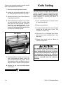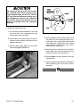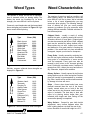
1
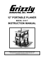
12'' PORTABLE PLANER
MODEL G1017
INSTRUCTION MANUAL
COPYRIGHT © 1991 BY GRIZZLY INDUSTRIAL, INC.
WARNING: NO PORTION OF THIS MANUAL MAY BE REPRODUCED IN ANY SHAPE
OR FORM WITHOUT THE WRITTEN APPROVAL OF GRIZZLY INDUSTRIAL, INC.
REVISED APRIL, 1999 PRINTED IN U.S.A.
Table Of Contents
PAGE
1.
2.
3.
4.
5.
6.
7.
8.
9.
-2-
SAFETY
SAFETY INSTRUCTIONS FOR POWER TOOLS..................................................3-4
ADDITIONAL SAFETY INSTRUCTIONS FOR PORTABLE PLANERS ....................5
CIRCUIT REQUIREMENTS
110V OPERATION ....................................................................................................6
GROUNDING ............................................................................................................6
GENERAL INFORMATION
COMMENTARY ........................................................................................................ 7
UNPACKING ..............................................................................................................8
PIECE INVENTORY ..................................................................................................8
CLEAN UP ................................................................................................................9
SITE CONSIDERATIONS ..........................................................................................9
ASSEMBLY
CHIP DEFLECTOR..................................................................................................10
HANDLE ASSEMBLY ..............................................................................................10
WOOD BASE ..........................................................................................................10
CONTROLS
ON/OFF SWITCH ....................................................................................................11
RESET BUTTON ....................................................................................................11
DEPTH OF CUT ......................................................................................................11
ADJUSTMENTS
EXTENSION WINGS ..............................................................................................12
FEED ROLLERS......................................................................................................12
PARALLELISM....................................................................................................13-14
KNIFE SETTING ................................................................................................14-15
OPERATIONS
TEST RUN ..............................................................................................................16
PLANING TIPS ........................................................................................................16
WOOD TYPES ........................................................................................................17
WOOD CHARACTERISTICS ............................................................................17-18
MAINTENANCE
GENERAL................................................................................................................19
LUBRICATION ........................................................................................................19
KNIFE SHARPENING ............................................................................................19
MOTOR....................................................................................................................20
V-BELT ....................................................................................................................20
FEED ROLLERS......................................................................................................21
CLOSURE ....................................................................................................................22
G1017 12'' Portable Planer
SECTION 1: SAFETY
For Your Own Safety Read Instruction
Manual Before Operating This Equipment
The purpose of safety symbols is to attract your attention to possible hazardous conditions. This
manual uses a series of symbols and signal words which are intended to convey the level of
importance of the safety messages. The progression of symbols is described below. Remember
that safety messages by themselves do not eliminate danger and are not a substitute for proper accident prevention measures.
Indicates an imminently hazardous situation which, if not
avoided, WILL result in death or serious injury.
Indicates a potentially hazardous situation which, if not avoided, COULD result in death or serious injury.
Indicates a potentially hazardous situation which, if not avoided, MAY result in minor or moderate injury. It may also be
used to alert against unsafe practices.
NOTICE
This symbol is used to alert the user to useful information
about proper operation of the equipment.
Safety Instructions For Power Tools
1.
KEEP GUARDS IN PLACE and in working
order.
2.
REMOVE ADJUSTING KEYS AND
WRENCHES. Form habit of checking to
see that keys and adjusting wrenches are
removed from tool before turning on.
3.
KEEP WORK AREA CLEAN. Cluttered
areas and benches invite accidents.
4.
DON’T USE IN DANGEROUS ENVIRONMENT. Don’t use power tools in damp or
wet locations, or where any flammable or
noxious fumes may exist. Keep work area
well lighted.
G1017 12'' Portable Planer
5.
KEEP CHILDREN AND VISITORS AWAY.
All children and visitors should be kept a
safe distance from work area.
6.
MAKE WORK SHOP CHILD PROOF with
padlocks, master switches, or by removing
starter keys.
7.
DON’T FORCE TOOL. It will do the job
better and safer at the rate for which it was
designed.
8.
USE RIGHT TOOL. Don’t force tool or
attachment to do a job for which it was not
designed.
-3-
Safety Instructions For Power Tools
9.
USE PROPER EXTENSION CORD. Make
sure your extension cord is in good condition. Conductor size should be in accordance with the chart below. The amperage
rating should be listed on the motor or tool
nameplate. An undersized cord will cause a
drop in line voltage resulting in loss of
power and overheating.Your extension cord
must also contain a ground wire and plug
pin. Always repair or replace extension
cords if they become damaged.
Minimum Gauge for Extension Cords
AMP RATING
0-6
7-10
11-12
13-16
17-20
21-30
LENGTH
25ft 50ft 100ft
18
16
16
18
16
14
16
16
14
14
12
12
12
12
10
10
10
No
10. WEAR PROPER APPAREL. Do not wear
loose clothing, gloves, neckties, rings,
bracelets, or other jewelry which may get
caught in moving parts. Non-slip footwear
is recommended. Wear protective hair covering to contain long hair.
11. ALWAYS USE SAFETY GLASSES. Also
use face or dust mask if cutting operation is
dusty. Everyday eyeglasses only have
impact resistant lenses, they are NOT safety glasses.
13. DON’T OVERREACH. Keep proper footing
and balance at all times.
14. MAINTAIN TOOLS WITH CARE. Keep
tools sharp and clean for best and safest
performance. Follow instructions for lubricating and changing accessories.
15. DISCONNECT TOOLS before servicing
and changing accessories, such as blades,
bits, cutters, and the like.
16. REDUCE THE RISK OF UNINTENTIONAL STARTING. Make sure switch is in off
position before plugging in.
17. USE RECOMMENDED ACCESSORIES.
Consult the owner’s manual for recommended accessories. The use of improper
accessories may cause risk of injury.
18. CHECK DAMAGED PARTS. Before further use of the tool, a guard or other part
that is damaged should be carefully
checked to determine that it will operate
properly and perform its intended function.
Check for alignment of moving parts, binding of moving parts, breakage of parts,
mounting, and any other conditions that
may affect its operation. A guard or other
part that is damaged should be properly
repaired or replaced.
19. NEVER LEAVE TOOL RUNNING UNATTENDED. TURN POWER OFF. Don’t leave
tool until it comes to a complete stop.
12. SECURE WORK. Use clamps or a vise to
hold work when practical. It’s safer than
using your hand and frees both hands to
operate tool.
-4-
G1017 12'' Portable Planer
Additional Safety Instructions For The
Portable Planer
1.
Ensure that the machine is firmly secured
to a bench or the floor before use.
2.
Always be aware of the condition of the
wood you are planing. Pay particular attention to knots, splits, and other potential
areas where the grain may be getting
ready to separate.
3.
Perform machine inspection and maintenance services promptly when called for.
4.
Make sure the planer knives are sharp,
balanced, and set correctly and securely.
Operate planer only with both knives in the
cutterhead.
5.
Do not plane any man-made composites
such as plywood, hardboard, particle
board, fiber board, flake board, fiberglass
and/or any other material other than solid,
natural wood fiber.
Like all power tools, there is danger associated with the Model G1017 Portable Planer.
Accidents are frequently caused by lack of
familiarity or failure to pay attention. Use
this tool with respect and caution to lessen
the possibility of operator injury. If normal
safety precautions are overlooked or
ignored, serious personal injury may occur.
G1017 12'' Portable Planer
6.
Position yourself so as not to get caught
(pinned) between the lumber and another
obstruction during the planing operation.
Also, ensure that there is sufficient clearance for the material being fed.
7.
Keep hands and fingers away from moving
parts and away from the infeed and outfeed
section of the planer. Do not reach into the
machine at any time for any reason without
first turning the switch off, pulling the electrical plug and after the machine has come
to a full stop.
8.
Any glued-up stock must be completely set
up and dry before planing.
9.
Never leave the planer running unattended.
10. Habits – good and bad – are hard to break.
Develop good habits in your shop and safety will become second-nature to you.
Operating this equipment has the potential
to propel debris into the air which can
cause eye injury. Always wear safety glasses or goggles when operating equipment.
Everyday glasses or reading glasses only
have impact resistant lenses, they are not
safety glasses. Be certain the safety glasses you wear meet the appropriate standards of the American National Standards
Institute (ANSI).
-5-
SECTION 2: CIRCUIT REQUIREMENTS
110V Operation
The G1017 planer operates on 110 volts. Under
normal use, the motor draws approximately 16
amps at 110V. We recommend a 20 amp circuit
breaker for 110V. This should be satisfactory for
normal use, while providing enough protection
against motor damage caused by power surges.
Grizzly recommends that the circuit you use
should be dedicated, (i.e., the G1017 should provide the only draw from that circuit). If frequent
circuit failures occur when using the planer, contact our service department or your local electrical contractor.
is necessary, do not connect the equipment
grounding conductor to a live terminal.
Under no circumstances should the grounding pin
from any three-pronged plug be removed. If it will
not fit the outlet, have the proper outlet installed
by a qualified electrician.
Check with a qualified electrician or one of our
service personnel if the grounding instructions
are not completely understood, or if in doubt as to
whether the tool is properly grounded. Use only 3wire extension cords that have 3-prong grounding
type plugs and 3-hole receptacles that accept the
tool’s plug. See FIgure 1.
Repair or replace damaged or worn cord immediately.
Be sure that your particular electrical configuration complies with local and state
codes. The best way to ensure compliance
is to check with your local municipality or
licensed electrician. Serious personal injury
may occur.
Grounding
In the event of a malfunction or breakdown,
grounding provides a path of least resistance for
electric current to reduce the risk of electric
shock. This tool is equipped with an electric cord
having an equipment-grounding conductor and a
grounding plug. The plug must be plugged into a
matching outlet that is properly installed and
grounded in accordance with all local codes and
ordinances.
Improper connections of the electrical-grounding
conductor can result in risk of electric shock. The
conductor with green or green and yellow striped
insulation is the electrical-grounding conductor. If
repair or replacement of the electric cord or plug
G1017 12'' Portable Planer
Figure 1. Typical 3-prong plug and outlet.
This equipment must be grounded. Verify
that any existing electrical outlet and circuit
you intend to plug into is actually grounded.
If it is not, it will be necessary to run a separate 12 A.W.G. copper grounding wire from
the outlet to a known ground. Under no circumstances should the grounding pin from
any three-pronged plug be removed.
Serious personal injury may occur.
G1017 12'' Portable Planer
SECTION 3: GENERAL INFORMATION
Commentary
Grizzly Industrial, Inc. is proud to offer the Model
G1017 12" Portable Planer. This planer is a part
of Grizzly’s growing family of fine machinery.
When used according to the guidelines described
in this manual, you can expect years of troublefree, enjoyable operation and proof of Grizzly’s
commitment to customer satisfaction.
The Model G1017 is a wood planer designed for
portable or small shop use. This planer features a
2 HP motor, four steel column supports for
increased strength, chain-driven feed rollers,
extension wings, and a direct reading thickness
gauge.
We are also pleased to provide this manual with
the G1017. It was written to guide you through
assembly, review safety considerations, and
cover general operating procedures. It represents
our latest effort to produce the best documentation possible. If you have any criticisms that you
feel we should pay attention to in our next printing, please write to us at the address below:
The specifications, drawings, and photographs
illustrated in this manual represent the Model
G1017 as supplied when the manual was prepared. However, owing to Grizzly’s policy of continuous improvement, changes may be made at
any time with no obligation on the part of Grizzly.
Whenever possible, though, we send manual
updates to all owners of a particular tool or
machine. Should you receive one, we urge you to
insert the new information with the old and keep
it for reference.
To operate this, or any power tool, safely and
efficiently, it is essential to become as familiar
with its characteristics as possible. The time
you invest before you begin to use your Model
G1017 will be time well spent. DO NOT operate
this machine until you are completely familiar
with the contents of this manual. Make sure you
read and understand all of the safety procedures. If you do not understand something, DO
NOT operate the machine.
Grizzly Industrial, Inc.
/O Technical Documentation
P.O. Box 2069
Bellingham, WA 98227-2069
C
Most importantly, we stand behind our machines.
We have excellent regional service departments
at your disposal, should the need arise. If, after
reviewing this manual carefully, you have any service questions or parts requests, please call or
write us at the location listed below.
Grizzly Industrial, Inc.
2406 Reach Road
Williamsport, PA 17701
Phone: 1-570-326-3806
FAX: 1-800-438-5901
E-Mail: [email protected]
Web Site:http://www.grizzlyindustrial.com
G1017 12'' Portable Planer
-7-
Unpacking
Piece Inventory
The Model G1017 12'' Planer is shipped from the
manufacturer in a carefully packed carton. If you
discover the machine is damaged after you’ve
signed for delivery, please call Customer Service
immediately for advice.
After all the parts have been removed from the
carton, you should have:
Save the containers and all packing materials for
possible inspection by the carrier or its agent.
Otherwise filing a freight claim can be difficult.
The G1017 is a heavy machine (85 lbs. shipping weight). DO NOT over-exert yourself
while unpacking or moving your machine –
get assistance. In the event that your planer
must be moved up or down a flight of stairs,
be sure that the stairs are capable of supporting the combined weight of people and
the machine. Serious personal injury may
occur.
•
•
•
•
•
•
•
•
•
•
Manual
Planer
Chip Deflector
Handle
8-10 mm Wrench
12-14 mm Wrench
Allen® Wrenches 3, 4, 5 & 6mm
Combination Screw Driver
Knife Gauge
Hardware
Lag Bolts 5⁄16" x 13⁄4"
4
3
Washers
⁄8"
4
In the event that any non-proprietary parts are
missing (e.g. a nut or a washer), we would be glad
to replace them, or, for the sake of expediency,
replacements can be obtained at your local hardware store.
When you are completely satisfied with the condition of your shipment, you should inventory its
parts.
-8-
G1017 12'' Portable Planer
Clean up
Site Considerations
The unpainted surfaces are coated with a waxy
oil to protect it from corrosion during shipment.
Remove this protective coating with a solvent
cleaner or citrus-based degreaser. Avoid chlorine-based solvents as they may damage painted
surfaces should they come in contact. Always follow the usage instructions on the product you
choose for clean up.
The Model G1017 is designed to be portable.
There are handles on both sides of the planer to
aid in lifting and moving. Before moving the planer, fold the depth control handle down, the extension wings up and ensure that the power cord is
disconnected.
Many of the solvents commonly used to
clean machinery can be highly flammable,
and toxic when inhaled or ingested. Always
work in well-ventilated areas far from potential ignition sources when dealing with solvents. Use care when disposing of waste
rags and towels to be sure they do not create fire or environmental hazards. Keep
children and animals safely away when
cleaning and assembling this machine.
1. Working Clearances: Consider existing
and anticipated needs, size of material to
be processed through each machine, and
space for auxiliary stands, work tables or
other machinery when establishing a location for your planer.
2. Lighting and Outlets: Lighting should be
bright enough to eliminate shadow and prevent eye strain. Electrical circuits should be
dedicated or large enough to handle
amperage requirements. Outlets should be
located near each machine so power or
extension cords are clear of high-traffic
areas. Observe local electrical codes for
proper installation of new lighting, outlets,
or circuits.
Do not use gasoline or other petroleumbased solvents to remove this protective
coating. These products generally have low
flash points which makes them extremely
flammable. A risk of explosion and burning
exists if these products are used. Serious
personal injury may occur.
The cutterhead knives on the G1017 planer
are extremely sharp. Merely brushing your
finger along the edge can result in a severe
cut. Take extreme caution when doing any of
the adjustments involving the cutterhead
knives. Wear thick gloves anytime it is necessary to manually rotate the cutterhead
assembly.
G1017 12'' Portable Planer
-9-
SECTION 4: ASSEMBLY
Chip Deflector
Wooden Base
For your safety and proper machine operation,
ensure that the chip deflector is secured before
use. The chip deflector directs wood chips away
from the cutterhead during operation and covers
the cutterhead and feed rollers for operator safety. To secure the chip deflector:
The wooden base yields greater stability and
enables the planer to be fastened to a sturdy
bench or floor when planing long stock. To construct the wooden base pieces:
1. Remove the two socket head cap screws at
the rear of the planer.
1. Mill two pieces of wood 17'' (L) x 2'' (W) x 2''
(H). Do not use planer for constructing base
pieces until it is checked out and adjustments have been made as required.
2. Set chip deflector in place and replace the
two socket head cap screws. See Figure 2.
2. Layout the two planer mounting hole locations on each piece.
3. Predrill mounting holes and mount the planer using four 5⁄16'' lag bolts and washers provided. See Figure 3.
Alternatively, the planer can be directly mounted
to a bench or table top, or to a Shop Fox® Deluxe
Tool Table utilizing these same mounting holes,
using the appropriate fasteners.
Figure 2. Chip deflector mounting screws.
Handle Assembly
Attach the handle assembly to the shaft protruding out of the top of the planer. Align the handle
with the notch, and tighten the M6-1 x 10mm cap
screw. Do not over tighten.
-10-
Figure 3. Mounting planer to wooden base.
G1017 12'' Portable Planer
SECTION 5: CONTROLS
On-Off Switch
Depth Of Cut
The on-off switch is located on the front of the
planer. See Figure 4. The switch has a key which,
when removed, allows the switch to be locked in
the “off” position. To access the locking feature,
push the switch to the “off” position and pull the
switch key out.
The planing depth is controlled by the crank handle on top of the planer. To extend the handle up
for operation, pull out on the handle while folding
it up. Turning the handle clockwise raises the cutterhead and counter-clockwise lowers the cutterhead. See Figure 5. Depth of cut is read directly
from the inch/millimeter scale located on the top,
right side of the planer. The minimum reading is
1
⁄16'' (1 mm). One complete turn of the handle raises or lowers the cutterhead approximately 1⁄16''
(1mm). The range of material thickness that can
be planed is 1⁄4'' - 5'' (5mm - 127mm).
Reset Button
Figure 4. Location of switch and reset button.
Reset Button
Figure 5. Depth of cut adjustment handle.
The G1017 Planer comes equipped with a thermal overload protection switch inside the motor.
To reset the switch, turn off the on-off switch, wait
a few seconds and then depress the reset button.
See Figure 4. If the reset button does not stay
depressed, wait longer before resetting.
G1017 12'' Portable Planer
-11-
SECTION 6: ADJUSTMENTS
Extension Wings
Your planer is equipped with front and rear extension wings. Each wing folds up for machine mobility and down for machine operation. To check
alignment, lay a straightedge across the bed and
wings. See Figure 6.
3. Move the straightedge to the other side of
the bed and repeat step two. Re-check to
ensure consistency from side to side.
Without turning the set bolts, tighten the
lock nuts.
4. To adjust the second wing, repeat steps
one through three above.
If adjustment is necessary, proceed as follows:
1. Use the 10mm wrench and loosen the locking nuts and set bolts underneath each
extension wing.
Feed Rollers
2. Hold a straightedge across the bed and
wing and turn the setscrews so the end of
the wing moves back into the same plane
as the planer bed.
The infeed and outfeed rollers are made of high
quality rubber and provide effective gripping pressure during operation. The delivery speed is 26
FPM (8 MPM). The infeed and outfeed roller pressure was pre-set at the factory and requires no
adjustment.
The cutterhead knives on the G1017 planer
are extremely sharp. Merely brushing your
finger along the edge can result in a severe
cut. Take extreme caution when doing any of
the adjustments involving the cutterhead
knives. Wear thick gloves anytime it is necessary to manually rotate the cutterhead
assembly.
Figure 6. Aligning extension wings.
Make sure the G1017 is unplugged or disconnected from the power source and moving parts have come to a complete stop
before investigating any problems or performing any maintenance or adjustments.
Serious personal injury may occur.
-12-
G1017 12'' Portable Planer
Parallelism
Before leaving the factory, the planer cutterhead
was set parallel to the planer bed for even cutting.
However, periodic inspections should be done to
ensure accuracy, especially if the planer is jostled
during transport. To check parallelism between
the cutterhead and bed, switch planer off, wait for
moving parts to stop and proceed as follows:
1. Construct a hardwood gauge as shown in
Figure 7.
2. Raise the cutterhead so that the wood
gauge fits between the edge of the knife in
the cutterhead and the planer bed. Place
the gauge to one end of the cutterhead.
Adjust the crank handle so the knife edge
just makes contact with the gauge at its
lowest point. See Figure 8.
3. Shift the hardwood gauge to the other end
of the cutterhead without changing the
position of the cutterhead. If the block
begins to bind against the cutterhead as
you move to the opposite end, lower the
table and go back to step 2, starting at this
end instead.
4. Check to see if there is any gap between
the knife edge and the block at the other
end. The knife edge should just touch the
block all the way along the length of the
knife.
45˚
.5''
3''
1⁄8''
30˚
13⁄8''
23⁄8''
1⁄2''
11⁄2''
Figure 7. Hardwood gauge dimensions.
The cutterhead knives on the G1017 planer
are extremely sharp. Merely brushing your
finger along the edge can result in a severe
cut. Take extreme caution when doing any of
the adjustments involving the cutterhead
knives. Wear thick gloves anytime it is necessary to manually rotate the cutterhead
assembly.
G1017 12'' Portable Planer
Figure 8. Using gauge to check cutterhead.
-13-
If there is any variation between one side and the
other, make adjustments as follows:
Knife Setting
1. Remove the depth adjustment handle.
2. Loosen the six screws beneath the edge of
the head piece and remove the top cover.
3. Release the tension on the idler bracket by
loosening the Hex Bolt.
4. While maintaining the position of one of the
two end sprockets (A), lift the drive chain
and rotate the other sprocket to raise or
lower the cutterhead assembly in the
desired direction. See Figure 9. It is important that the designated fixed sprocket does
not move for consistent results.
Idler Bracket
A
The G1017 Planer is equipped with a 2 blade cutterhead. The blades are set by adjustable screws
and are locked in position by wedge type gibs.
Disconnect the power cord from the power source
before adjusting or removing the knives. To
remove the knives:
1. Lower cutterhead down to provide access
to knives from the top.
2. Remove chip deflector.
3. Use open-ended wrench to loosen the bolts
locking the gib and knife in place. Turn
clockwise to loosen knife.
4. Slide knife out of cutterhead and remove
gib. Use care when handling knives - they
are sharp!
5. Repeat steps three and four above to
remove second knife.
Figure 9. Chain and sprocket adjustment.
5. Check parallelism between the knives and
bed. If both sides are parallel, secure the
chain and idler bracket into position. Set the
idler bracket so there is sufficient tension to
keep the chain in position on all sprockets.
The cutterhead knives on the G1017 planer
are extremely sharp. Merely brushing your
finger along the edge can result in a severe
cut. Take extreme caution when doing any of
the adjustments involving the cutterhead
knives. Wear thick gloves anytime it is necessary to manually rotate the cutterhead
assembly.
6. Replace the top cover and depth adjustment handle.
-14-
G1017 12'' Portable Planer
The cutterhead knives on the G1017 planer
are extremely sharp. Merely brushing your
finger along the edge can result in a severe
cut. Take extreme caution when doing any of
the adjustments involving the cutterhead
knives. Wear thick gloves anytime it is necessary to manually rotate the cutterhead
assembly.
To install and adjust the knives:
1. Turn leveling screws clockwise so the knife
will be set low in the cutterhead using the
socket head wrench provided.
2. Insert knife and loosened gib into the cutterhead. Ensure that the knife bevel side is
against cutterhead.
3. Position knife setting gauge on the cutterhead. See Figures 10 and 11.
Figure 11. Side view of cutterhead and gauge.
4. While holding the knife setting gauge with
one hand, turn the leveling screw(s) counterclockwise, thus, raising the knife until the
knife edge just contacts the knife setting
gauge. Do this on both sides of the cutterhead. Repeat if necessary.
5. When the knife is correctly set in the cutterhead, tighten the gib bolts against the cutterhead using the open end wrench.
6. Repeat Steps 1 through 5 above to set the
second knife.
7. Check all gib bolts for tightness. Remember,
when tightening gibs, turn bolts counterclockwise.
Figure 10. Knife gauge on cutterhead.
G1017 12'' Portable Planer
-15-
SECTION 7: OPERATIONS
Test Run
Planing Tips
Once assembly is complete and adjustments are
done to your satisfaction, you are ready to test the
machine. Make certain you have removed any
tools or gauges used in the adjustment or assembly process from the bed of the planer.
•
Inspect your lumber for twist or cup and surface one face on a jointer if necessary.
•
Scrape all glue off when planing laminated
stock.
Turn on the power supply at the main panel.
Press the ON button. Make sure that your finger
is poised on the OFF button, just in case there’s
a problem. The planer should run smoothly, with
little or no vibration or rubbing noises. Strange or
unnatural noises should be investigated and corrected before operating the machine further.
•
Plane boards of equal thicknesses when
planing multiples.
•
Remove only 1⁄32'' to 1⁄16'' (.8mm to 1.6mm) of
material on each pass. Remove less material in each pass when planing wide or dense
stock.
If you cannot easily locate the source of an
unusual noise or vibration, feel free to contact our
service department for help.
•
Support lumber on both ends. Get assistance
if planing long lumber, or use roller stands.
•
Measure workpiece with calipers to get exact
results.
•
Check surface of workpiece for any irregularities.
•
Plane equal amounts on each side of the
board to reduce the chance of warpage.
•
Use entire width of planer to wear knives
evenly.
•
Surface wood with the grain. Never feed any
end cut or end grained wood through the
machine.
Make sure the G1017 is unplugged or disconnected from the power source and moving parts have come to a complete stop
before investigating any problems or performing any maintenance or adjustments.
Serious personal injury may occur.
-16-
G1017 12'' Portable Planer
Wood Types
Wood Characteristics
The species of wood, as well as its condition,
have a dramatic effect on planing ability. The
harder the wood (as illustrated by its shear
strength), the more difficult it will be to plane.
The species of wood, as well as condition, will
affect planing ability. The harder the wood, the
more difficult it will be to plane. We’ve included
below, a list of wood characteristics you may
encounter when planing. The following descriptions of defects will give you some possible
answers to problems you may encounter while
planing different materials. Possible solutions follow the descriptions.
Commonly used hardwoods and their associated
shear strengths are illustrated in Figure 12. High
shear means difficult planing.
Increasing
Difficulty
Type
Shear (PSI)
Black Locust
Sugar Maple
Pecan Hickory
White Oak
White Ash
Black Cherry
American Elm
Black Walnut
Red Alder
Basswood
Cottonwood
2,480
2,330
2,080
2,000
1,950
1,700
1,510
1,370
1,080
980
930
Figure 12. Common hardwood shear strengths.
Similarly, common softwood shear strengths are
displayed in Figure 13.
Increasing
Difficulty
Type
Shear (PSI)
Western Larch
Tamarack
Douglas Fir
Alaska Cedar
Sitka Spruce
Sugar Pine
Cypress
Redwood (OG)
Red Cedar
White Pine
Balsam Fir
1,410
1,280
1,160
1,130
1,150
1,050
1,000
940
860
850
710
Figure 13. Common softwood shear strengths.
G1017 12'' Portable Planer
Chipped Grain - usually a result of cutting
against the grain, or planing wood with knots or
excessive amount of cross grain. Chipped grain
can also be caused by dull knives. Often, chipped
grain can be avoided by taking shallow cuts. If
those options do not work, inspect your lumber
and determine if its grain pattern is causing the
problem. If the wood does not show substantial
crossgrain, inspect your knives for sharpness.
Fuzzy Grain - Usually caused by surfacing lumber with too high a moisture content. Sometimes
fuzzy grain is a characteristic of some woods,
such as basswood. Fuzzy grain can also be
caused by dull knives or an incorrect grinding
bevel. Check with a moisture meter. If moisture is
greater than 20%, sticker the wood and allow to
dry. Otherwise, inspect knife condition.
Glossy Surface - Usually caused by dull knives
taking shallow cuts at a slow feed speed. Surface
gloss will usually be accompanied by overheating. Often, lumber will be scorched and eventually, damage to knives will occur.
Snipe - Occurs when board ends have more
material removed than the rest of the board.
Usually caused when one or both of the bed
rollers are set too low. However, small amount of
snipe is inevitable. The best way to deal with
snipe is by planing lumber longer than your
intended work length and then cutting off the
excess after planing is completed.
Wavy Surface - Caused by poor knife height
adjustment, wavy surface appears when one
knife is taking deeper cuts than the rest of the
knives. Recheck or reset knife height to ±.001''.
-17-
Pitch & Glue Build-up - Glue and resin build-up
on the rollers and cutterhead will cause overheating by decreasing cutting sharpness while
increasing drag in the feed mechanism. The
result can include scorched lumber as well as
uneven knife marks and chatter.
Notes
Chip Marks or Indentations- Chip indentation or
chip bruising is the result of wood chips not being
thrown away from the cutterhead and out of the
dust chute. Instead they are carried around the
cutterhead, deposited on the planed surface and
crushed by the outfeed roller. Chip indentations
can be caused by a number of reasons, some of
which are:
1. The type of lumber being planed. Certain
species have a tendency to chip bruise.
2. A high moisture content (over 15%) and/or
surface moisture. Typically found in airdried stock where the surface is dry but the
inside needs a longer time to season.
3. An inefficient dust collection system without
enough suction capacity or an incorrectly
engineered and assembled system.
4. Dull knives.
5. Too much material being removed in one
pass.
6. Improper knife cutting angle.
Possible Solutions:
1. Lumber must be completely dry, preferably
kiln-dried (KD). Air-dried (AD) lumber must
be seasoned properly and have no surface moisture. Do not surface partially-airdried (PAD) lumber.
2. Make sure planer knives are sharp.
3. Use an adequate dust collection system,
one that uses relatively few turns and is as
air tight as possible.
4. Remove less material per pass.
5. Use a smaller cutting angle or a double
bevel grind (consult a reputable knife
grinder).
-18-
G1017 12'' Portable Planer
SECTION 8: MAINTENANCE
General
Knife Sharpening
Regular periodic maintenance on your Model
G1017 Planer will ensure its optimum performance. Make a habit of inspecting your planer
each time you use it. Check for the following conditions and repair or replace when necessary.
Knife sharpness is one of the most important factors in getting good results with the planer. Knives
can be made to last a long time if care is taken in
checking the condition of the wood which is put
into the machine. The biggest problem will come
from wood with nails or other metal embedded.
This will nick or chip the knives and can require a
complete regrinding. Another wear factor is sand,
grit, or other dirt on the surface of the wood which
the knives have to cut through. At the speed the
cutterhead is rotating, these types of surface contamination can have a very abrasive effect.
Routinely check the condition of the following items and repair or replace as necessary:
• Loose mounting bolts, extension
wings, or handles, or excessive play
in the depth of cut adjustment.
• Worn switch.
• Worn or damaged cords or plugs.
• Dull or damaged cutterhead knives.
• Any condition that could hamper the
safe operation of the machine.
Serious personal injury may occur.
This planer has knives with a grind angle of 50˚
which is a configuration which should suit most
general planing needs. The optimal grind or bevel
angle is a compromise between effective cutting
(the smaller the angle the better the cutting
action) and edge life where the larger the angle
the more the edge is supported, thus the longer it
will last.
Since all bearings are shielded and permanently
lubricated, simply leave them alone until they
need to be replaced. Do not lubricate them.
For the best results it is best to have planer knives
sharpened by a professional sharpening service
which has the grinding and measurement equipment to assure that the knife cutting geometry is
maintained at optimum levels. It is a procedure
which requires some care and precision, otherwise a set of blades can be easily ruined. Knives
should always be ground as a set so they can be
properly matched. Unequal material removal can
result in an unbalanced cutterhead which can
affect not only planing surface quality but ultimately the life of the cutterhead bearings.
As for other items on this machine, such as the
depth adjusting screw-threads, an occasional
“shot” of light oil is all that is necessary.
Please refer to Section 6 Adjustments - Knife
Setting for complete detail on the removal and
reinstallation of planer knives.
Lubrication
G1017 12'' Portable Planer
-19-
Motor
V-Belt
Keep the motor as clean as possible. Prevent any
water, oil or wood chips from penetrating inside
the motor. Be sure to clean the machine after
every use. Do not use compressed air to remove
saw dust. Dust may be forced into normally protected parts which may cause damage to the
machine.
The cutterhead is driven by a rubber V-belt located on the left side of the motor and cutterhead
assembly. The feed rollers are driven by a chain
on the right side of the motor and cutterhead
assembly. To inspect or remove the V-belt:
The bearings inside the motor are also shielded
and lubricated for the life of the bearing and
require no routine maintenance.
1. Lower the cutterhead assembly and leave a
gap along the front edge of 11⁄2'' to the table.
2. Remove the Belt Guard Cover.
3. ''Roll off'' the old belt toward the side of the
elevation screw.
4. Loop the new belt so that it completely surrounds the motor pulley but with only half
the "vees" engaged. Start the lower portion
on the underside of the cutterhead pulley
and slowly rotate the motor pulley with your
free hand.
5. By pushing on the edge of the belt and
slowly turning the pulleys by hand, you can
force the belt over until all the "vees" of the
belt are in alignment with the "vees" on the
pulley.
Figure 14. Brush holder location.
6. Replace the belt guard.
This motor is equipped with long life carbon
brushes. However, brush life expectancy is affected by motor loading. Planing very wide, dense
boards or cutting too deep will reduce brush life.
Check brushes after every ten to fifteen hours of
operation. See Figure 14. When the brushes are
worn down to 1⁄4'' (6mm), it is time for replacement. When checking brushes, be sure to replace
each brush in the same position and the same
location that it came from. When replacing old
brushes, be sure to replace both brushes at the
same time.
-20-
G1017 12'' Portable Planer
Feed Rollers
The feed rollers rotate in bushing blocks that are
spring-loaded. The feed rollers ride up on the
board so roller pressure is maintained. If chips or
sawdust build up between the bracket and bushing block, the amount of roller vertical travel will
be reduced. See Figure 15.
Routinely check and clean chips and sawdust
from between the bushing blocks and brackets. To
depress the rollers so that chips and sawdust can
be easily removed:
1. Place a 5'' block of wood between one of
the feed rollers and the planer bed. Ensure
that the block of wood is not under the cutterhead.
2. Lower the cutterhead assembly down just
enough so that the roller pressure is off of
the two brackets.
3. Remove any trapped material from
between the roller assembly and bracket.
4. Raise the cutterhead assembly and remove
the block of wood.
Repeat Steps 1 through 4 above to clean chips
and sawdust from the second feed roller.
Remove trapped sawdust from between
the bushing block and the bracket
Figure 15. Location of potential trapped sawdust.
G1017 12'' Portable Planer
-21-
SECTION 9: CLOSURE
The following pages contain parts diagrams / lists,
general machine data and Warranty/Return information for your Model G1017 12'' Planer.
If you need parts or help in assembling your
machine, or if you need operational information,
we encourage you to call our Service
Department. Our trained service technicians will
be glad to help you.
If you have comments dealing specifically with
this manual, please write to our Bellingham,
Washington location using the address in the
General Information section. The specifications,
drawings, and photographs illustrated in this manual represent the Model G1017 as supplied when
the manual was prepared. However, due to
Grizzly’s policy of continuous improvement,
changes may be made at any time with no obligation on the part of Grizzly. Whenever possible,
though, we send manual updates to all owners of
a particular tool or machine. Should you receive
one, add the new information to this manual and
keep it for reference.
We have included some important safety measures that are essential to this machine’s operation. While most safety measures are generally
universal, Grizzly reminds you that each workshop is different and safety rules should be considered as they apply to your specific situation.
-22-
We recommend you keep a copy of our current
catalog for complete information regarding
Grizzly's warranty and return policy. If you need
additional technical information relating to this
machine, or if you need general assistance or
replacement parts, please contact the Service
Department listed in Section 3: General
Information.
Additional information sources are necessary to
realize the full potential of this machine. Trade
journals, woodworking magazines, and your local
library are good places to start.
As with all power tools, there is danger
associated with the Model G1017 12"
Portable Planer. Use the tool with respect
and caution to lessen the possibility of
mechanical damage or operator injury. If
normal safety precautions are overlooked
or ignored, serious personal injury may
occur.
The Model G1017 was specifically designed for
planing operations. DO NOT MODIFY AND/OR
USE THIS PLANER FOR ANY OTHER PURPOSE. Modifications or improper use of this
tool will void the warranty. If you are confused
about any aspect of this machine, DO NOT use
it until you have answered all your
questions.Serious injury may occur.
G1017 12'' Portable Planer