1
®
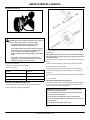
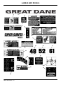
Super Surfer Series II
GSKH1848S, GSKH2352S, GSKH2561S
GSKW1948S, GSKW2352S, GSKA1948S
OPERATOR’S MANUAL
200036 REV. 04/11/2007
North American Version
Introduction
Using Your Operator’s Manual
This manual is an important part of your machine and should remain with
the machine when you sell it.
Use the safety and operating information in the machine operator’s
manual to operate and service the machine safely and correctly.
An engine manufacturer’s owner’s manual has been provided with your
machine. This will provide maintenance and troubleshooting information
for the engine installed in your machine.
Specifications and design are subject to change without notice.
WARNING: The Engine Exhaust
from this product contains chemicals known
to the State of California to cause cancer,
birth defects or other reproductive harm.
California Proposition 65 Warning
Special Messages
Your manual contains special messages to bring attention to potential
safety concerns, machine damage as well as helpful operating and
servicing information. Please read all the information carefully to avoid
injury and machine damage.
c
CAUTION: Avoid injury! This symbol and text highlight
potential hazards or death to the operator or
bystanders that may occur if the hazards or
procedures are ignored.
IMPORTANT: Avoid Damage! This text is used to tell the operator
of actions or conditions that might result in damage to the
machine.
NOTE: General information is given throughout the manual that may
help the operator in the operation or service of the machine.
Product Identification
Record Identification Numbers
Super Surfer
GSKH18-48S Serial Number (636510001-)
GSKH23-52S Serial Number (636610001-)
GSKH25-61S Serial Number (636710001-)
GSKW1948S Serial Number (636410001-)
GSKW2352S Serial Number (637010001-)
GSKA1948S Serial Number (6373010001-)
All information, illustrations and
specifications in this manual are based on
the latest information at the time of
publication. The right is reserved to make
changes at any time without notice.
COPYRIGHT© 2007
Auburn Consolidated Industries, Inc.
All rights reserved
Previous Editions
COPYRIGHT© 2002
If you need to contact an Authorized Service Center for information on
servicing, always provide the product model and serial numbers.
You will need to locate the model and serial numbers for the machine and
for the engine of your machine and record the information in the spaces
provided.
DATE OF PURCHASE:
_________________________________________
DEALER NAME:
_________________________________________
DEALER PHONE:
_________________________________________
PRODUCT IDENTIFICATION NUMBER:
Model Number
_________________________________________
Serial Number
_________________________________________
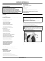
SAFETY LABELS
Safety Labels
ENGINE MODEL, SPECIFICATION, AND SERIAL NUMBER:
c
Model Number
_________________________________________
Specification
_________________________________________
Serial Number
_________________________________________
Safety Labels
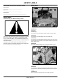
Understanding The Machine Safety Labels
c
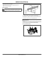
MX20097
WARNING (A)
Hot Surface.
WARNING (B)
To avoid injury from rotating belts, keep all shields and guards in place.
Safety-Alert Symbol
The machine safety labels shown in this section are placed in important
areas on your machine to draw attention to potential safety hazards.
On your machine safety labels, the words DANGER, WARNING, and
CAUTION are used with this safety-alert symbol. DANGER identifies the
most serious hazards.
The operator’s manual also explains any potential safety hazards
whenever necessary in special safety messages that are identified with
the word, CAUTION, and the safety-alert symbol.
DANGER (C)
To avoid injury from rotating blades, stay clear of deck edge.
DANGER (D)
To avoid injury from rotating blades and thrown objects, stay clear of deck
edge and keep others away. Do not mow without discharge chute or entire
grass catcher in place.
DANGER (E)
Do not mow without discharge chute or entire grass catcher in place.
c
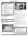
MX20138
DANGER (F)
To avoid injury to children, stop mower when children are near. Do not
mow in reverse. Look behind when backing. Never carry riders, especially
children.
CAUTION: (G)
Before operating read operators manual and safety instructions.
Safety Labels - 2
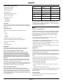
SAFETY
CAUTION: HELP AVOID INJURY (H)
• Operator training required
Agency
Category
Hours
• Read operator’s manual
EPA
C
250
EPA
B
500
EPA
A
1000
CARB
Moderate
125
CARB
Intermediate
250
CARB
Extended
500
• Keep shields in place
• Never carry riders
• Keep people a safe distance away
• Maintain all safety devices
• Before leaving machine:
• Stop engine
• Set park brake
Certification
• Remove key
CAUTION (I)
Be safe! To avoid a fire hazard remove all leaves, grass and debris from
engine, hydro pumps and motors, pulleys, belts, hoses, engine deck and
cutter deck.
Your product has been tested and evaluated by the manufacturer and
conforms with American National Standard B-71.4, “Safety Specifications”
for commercial turf care equipment.
Safety
DANGER/POISON (J)
Operator Training Required
• Shield Eyes: Explosive gases can cause blindness or injury.
• Read the operator’s manual and other training material. If the operator or
mechanic cannot read English, it is the owner’s responsibility to explain
this material to them. This publication is available in other languages.
• NO
• Sparks
• Become familiar with the safe operation of the equipment, operator
controls, and safety signs.
• Flames
• Smoking
• All operators and mechanics should be trained. The owner of the
machine is responsible for training the users.
• Sulfuric acid can cause blindness or severe burns.
• Flush eyes immediately with water. Get medical help fast.
• Never let children or untrained people operate or service the equipment.
Local regulations may restrict the age of the operator.
• Keep out of reach of children.
• The owner/user can prevent and is responsible for accidents or injuries
occurring to themselves, other people, or property.
• Do not tip.
• Do not open battery.
• Operate the machine in an open, unobstructed area under the direction
of an experienced operator.
WARNING (K)
To avoid injury from tipover, drive across slopes, not up and down. If
machine stops going uphill, stop blades and back down slowly.
Preparation
Emission Control System Certification Label
• Evaluate the terrain to determine what accessories and attachments are
needed to properly and safely perform the job. Only use accessories and
attachments approved by the manufacturer.
NOTE: Tampering with emission controls and components by
unauthorized personnel may result in severe fines or penalties.
Emission controls and components can only be adjusted by EPA
and/or CARB authorized service centers. Contact your Great Dane
Equipment Retailer concerning emission controls and component
questions.
The presence of an emissions label signifies that the engine has been
certified with the United States Environmental Protection Agency (EPA)
and/or California Air Resources Board (CARB).
The emissions warranty applies only to those engines marketed by Great
Dane that have been certified by the EPA and/or CARB; and used in the
United States and Canada in off-road mobile equipment.
Emission Compliance Period
• Wear appropriate clothing including hard hat, safety glasses and hearing
protection. Long hair, loose clothing or jewelry may get tangled in moving
parts.
• Inspect the area where the equipment is to be used and remove all
objects such as rocks, toys and wire which can be thrown by the machine.
• Use extra care when handling gasoline and other fuels. They are
flammable and vapors are explosive.
a. Use only an approved container.
b. Never remove gas cap or add fuel when engine is running. Do not
smoke.
c. Never refuel or drain the machine indoors.
If your engine has the emission compliance category listed on the
emission control system certification or air index label, this indicates the
number of operating hours for which the engine has been certified to meet
EPA and/or CARB emission requirements. The following table provides
the engine compliance period in hours associated with the category found
on the certification label.
• Check that the operator’s presence controls, safety switches and shields
are attached and functioning properly. Do not operate unless they are
functioning properly.
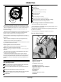
Operating Safely
• Never run an engine in an enclosed area where dangerous carbon
monoxide fumes can collect.
Safety - 3
SAFETY
Using a Spark Arrestor
• Only operate in good light, keeping away from holes and hidden
hazards.
• Be sure all drives are in neutral and parking brake is engaged before
starting engine. Only start engine from the operator’s position. Use seat
belts if provided.
• Slow down and use extra care on hillsides. Be sure to travel in the
recommended direction on hillsides. For this machine, drive across
hillsides, not up and down. Turf conditions can affect the machine’s
stability. Use caution while operating near drop-offs.
The engine in this machine is not equipped with a spark arrestor muffler. It
is a violation of California Public Resource Code Section 4442 to use or
operate this engine on or near any forest-covered, brush-covered or
grass-covered land unless the exhaust system is equipped with a spark
arrestor meeting any applicable local or state laws. Other states or federal
areas may have similar laws.
A spark arrestor for your machine may be available from your authorized
dealer. An installed spark arrestor must be maintained in good working
order by the operator.
• Slow down and use caution when making turns and when changing
directions on slopes.
Checking Mowing Area
• Never raise deck with the blades running.
• Evaluate the terrain to determine what accessories and attachments are
needed to properly and safely perform the job.
• Never operate with the PTO shield, or other guards, not securely in
place. Be sure all interlocks are attached, adjusted properly, and
functioning properly.
• Clear mowing area of objects that might be thrown. Keep people and
pets out of mowing area.
• Never operate with the discharge deflector raised, removed or altered,
unless using a grasscatcher. Do not operate mower without discharge
chute or entire grasscatcher in place.
• Do not change the engine governor setting or overspeed the engine.
Operating the engine at excessive speed can increase the hazard of
personal injury.
• Study mowing area. Set up a safe mowing pattern. Do not mow where
traction or stability is doubtful.
• Test drive area with mower lowered but not running. Slow down when
you travel over rough ground.
Parking Safely
• Stop on level ground, lower implements, disengage drives, engage
parking brake, and shut off engine before leaving the operator’s position
for any reason including emptying the grasscatchers or unclogging the
chute.
1. Stop machine on a level surface, not on a slope.
• Stop equipment and inspect blades after striking objects or if an
abnormal vibration occurs. Make necessary repairs before resuming
operations.
4. Stop the engine.
2. Disengage mower blades.
3. Lock the park brake.
5. Remove the key.
6. Wait for engine and all moving parts to stop before you leave the
operator’s station.
• Keep hands and feet away from the cutting units.
• Look behind and down before backing up to be sure of a clear path.
7. Close fuel shut-off valve, if your machine is equipped.
• Never carry passengers and keep pets and bystanders away.
• Slow down and use caution when making turns and crossing roads and
sidewalks. Stop blades if not mowing. Watch for traffic when operating
near or crossing roadways.
• Be aware of the mower discharge direction and do not point it at anyone.
8. Disconnect the negative battery cable or remove the spark plug wire
(for gasoline engines) before servicing the machine.
Rotating Blades are Dangerous
HELP PREVENT SERIOUS OR FATAL ACCIDENTS:
c
• Do not operate the machine while under the influence of alcohol or
drugs.
• Use care when loading or unloading the machine into or off of a trailer or
truck.
• Use care when approaching blind corners, shrubs, trees, or other objects
that may obscure vision.
• Inspect machine before you operate. Be sure hardware is tight. Repair or
replace damaged, badly worn, or missing parts. Be sure guards and
shields are in good condition and fastened in place. Make any necessary
adjustments before you operate.
• Before using, always visually inspect to see that the blades, blade bolts
and the mower assembly are not worn and damaged. Replace worn and
damaged blades and bolts in sets to preserve balance.
• Keep safety labels visible when installing accessories and attachments.
• Do not wear radio or music headphones. Safe service and operation
require your full attention.
• When machine is left unattended, stored, or parked, lower the mower
deck unless a positive mechanical lock is used.
• Rotating blades can cut off arms and legs, and throw objects. Failure to
observe safety instructions could result in serious injury or death.
• Keep hands, feet and clothing away from mower deck when engine is
running.
• Be alert at all times, drive forward carefully. People, especially children
can move quickly into the mowing area before you know it.
Safety - 4
SAFETY
• Tires may lose traction on slopes even though the brakes are functioning
properly.
• Do not mow in reverse.
• Shut off blades when you are not mowing.
• • Park machine safely before leaving the operator station for any reason
including emptying the catchers or unplugging the chute.
• Avoid starting, stopping or turning on a slope. If the tires lose traction,
disengage the blades and proceed slowly, straight down the slope.
• Keep all movement on slopes slow and gradual. Do not make sudden
changes in speed or direction, which could cause the machine to roll over.
Protect Children
c
• Use extra care while operating machine with grasscatchers or other
attachments, they can affect stability of the machine. Do not use on steep
slopes.
• Do not mow near drop-offs, ditches, embankments, or bodies of water.
The machine could suddenly roll over if a wheel goes over the edge or the
edge caves in.
• Follow the manufacturer’s recommendations for wheel weights or
counterweights for added stability when operating on slopes or using front
or rear mounted attachments. Remove weights when not required.
• Drive machine very slowly and avoid quick stops when attachment is
removed.
• Transport machine with decks lowered to improve stability.
MX18014
• Death or serious injury can occur when young children associate having
fun with a lawn mowing machine simply because someone has given
them a ride on a machine.
• Children are attracted to lawn mowing machines and mowing activities.
They don’t understand the dangers of rotating blades or the fact that the
operator is unaware of their presence.
• Children who have been given rides in the past may suddenly appear in
the mowing area for another ride and be run over or backed over by the
machine.
• Tragic accidents with children can occur if the operator is not alert to the
presence of children, especially when a child approaches a machine from
behind. Before and while backing up, stop mower blades and look down
and behind the machine carefully, especially for children.
Keep Riders Off
• Only allow the operator on the machine. Keep riders off.
• Riders on the machine or attachment may be struck by foreign objects or
thrown off the machine causing serious injury.
• Riders obstruct the operator’s view resulting in the machine being
operated in an unsafe manner.
Avoid High Pressure Fluids
• Hydraulic hoses and lines can fail due to physical damage, kinks, age,
and exposure. Check hoses and lines regularly. Replace damaged hoses
and lines.
• Hydraulic fluid connections can loosen due to physical damage and
vibration. Check connections regularly. Tighten loose connections.
• Never carry children on a machine or attachment, even with the blades
off. Do not tow children in a cart or trailer. They can fall off and be
seriously injured or interfere with safe machine operation.
• Escaping fluid under pressure can penetrate the skin causing serious
injury. Avoid the hazard by relieving pressure before disconnecting
hydraulic or other lines. Tighten all connections before applying pressure.
• Never use the machine as a recreational vehicle or to entertain children.
• Search for leaks with a piece of cardboard. Protect hands and body from
high pressure fluids.
• Never allow children or an untrained person operate the machine.
Instruct all operators not to give children a ride on the machine or in an
attachment.
• Keep children indoors, out of the mowing area, and in the watchful eye of
a responsible adult, other than the operator, when a mower is being
operated.
• Stay alert to the presence of children. Never assume that children will
remain where you last saw them. Turn the machine off if a child enters the
work area.
• If an accident occurs, see a doctor immediately. Any fluid injected into
the skin must be surgically removed within a few hours or gangrene may
result. Doctors unfamiliar with this type of injury should reference a
knowledgeable medical source. Such information is available from Deere
& Company Medical Department in Moline, Illinois, U.S.A. Information
may be obtained in the United States and Canada only by calling 1-800822-8262.
Checking Wheel Hardware
Avoid Tipping
• A serious accident could occur causing serious injury if wheel hardware
is not tight.
• Slopes are a major factor related to loss-of-control and tip-over
accidents, which can result in severe injury or death. Operation on all
slopes requires extra caution. Never mow on inclines exceeding 15°.
• Check wheel hardware tightness often during the first 100 hours of
operation.
• Mow across slopes, not up and down.
• Wheel hardware must be tightened to specified torque using the proper
procedure anytime it is loosened.
• Watch for holes, ruts, bumps, rocks, or other hidden objects. Uneven
terrain could overturn the machine. Tall grass can hide obstacles.
Wear Appropriate Clothing
• Choose a low ground speed so you will not have to stop or shift while on
a slope.
• Always wear safety goggles, or safety glasses with side shields, and a
hard hat when operating the machine.
• Do not mow or operate machine on wet grass. Tires may lose traction. • •
c
Safety - 5
SAFETY
• Wear close fitting clothing and safety equipment appropriate for the job.
• Empty the grasscatcher completely before storing.
• While mowing, always wear substantial footwear and long trousers. Do
not operate the equipment when barefoot or wearing open sandals.
• Always shut off fuel when storing or transporting machine, if the machine
has a fuel shutoff.
• Wear a suitable protective device such as earplugs. Loud noise can
cause impairment or loss of hearing.
• Do not store machine near an open flame or source of ignition, such as a
water heater or furnace.
c
• Check fuel lines, tank, cap, and fittings frequently for cracks or leaks.
Replace if necessary.
Maintenance and Storage
Tire Safety
• Never operate machine in a closed area where dangerous carbon
monoxide fumes can collect.
• Disengage drives, lower implement, lock parking brake, stop engine and
remove key or disconnect spark plug (for gas engines). Wait for all
movement to stop before adjusting, cleaning or repairing.
• Clean grass and debris from cutting units, drives, mufflers, and engine to
help prevent fires. Clean up oil or fuel spillage.
• Let engine cool before storing and do not store near flame.
• Shut off fuel while storing or transporting. Do not store fuel near flames
or drain indoors.
• Park machine on level ground. Never allow untrained personnel to
service machine. Understand service procedure before doing work.
• Use jack stands or lock service latches to support components when
required. Securely support any machine elements that must be raised for
service work.
Explosive separation of a tire and rim parts can cause serious injury or
death:
• Do not attempt to mount a tire without the proper equipment and
experience to perform the job.
• Always maintain the correct tire pressure. Do not inflate the tires above
the recommended pressure. Never weld or heat a wheel and tire
assembly. The heat can cause an increase in air pressure resulting in a
tire explosion. Welding can structurally weaken or deform the wheel.
• When inflating tires, use a clip-on chuck and extension hose long
enough to allow you to stand to one side and NOT in front of or over the
tire assembly.
• Check tires for low pressure, cuts, bubbles, damaged rims or missing lug
bolts and nuts.
Handling Fuel Safely
• Before servicing machine or attachment, carefully release pressure from
any components with stored energy, such as hydraulic components or
springs.
To avoid personal injury or property damage, use extreme care in
handling fuel. Fuel is extremely flammable and fuel vapors are
explosive:
• Release hydraulic pressure by lowering attachment or cutting units to the
ground or to a mechanical stop and move hydraulic control levers back
and forth.
• Extinguish all cigarettes, cigars, pipes, and other sources of ignition.
• Disconnect battery or remove spark plug (for gas engines) before
making any repairs. Disconnect the negative terminal first and the positive
last. Reconnect positive first and negative last.
• Use care when checking blades. Wrap the blades or wear gloves, and
use caution when servicing them. Only replace blades. Never straighten
or weld them.
• Keep hands, feet, clothing, jewelry and long hair away from moving
parts. If possible, do not make adjustments with the engine running.
• Charge batteries in an open well ventilated area, away from spark and
flames. Unplug charger before connecting or disconnecting from battery. •
Wear protective clothing and use insulated tools.
• Keep all parts in good working condition and all hardware tightened.
Replace all worn or damaged decals.
• Use only an approved fuel container. Use only non-metal, portable fuel
containers approved by the Underwriter’s Laboratory (U.L.) or the
American Society for Testing & Materials (ASTM). If using a funnel, make
sure it is plastic and has no screen or filter.
• Never remove the fuel tank cap or add fuel with the engine running.
Allow engine to cool before refueling.
• Never add fuel to or drain fuel from the machine indoors. Move machine
outdoors and provide adequate ventilation.
• Clean up spilled fuel immediately. If fuel is spilled on clothing, change
clothing immediately. If fuel is spilled near machine, do not attempt to start
the engine but move the machine away from the area of spillage. Avoid
creating any source of ignition until fuel vapors have dissipated.
• Never store the machine or fuel container where there is an open flame,
spark, or pilot light such as on a water heater or other appliance.
c
• Check grasscatcher components and the discharge guard frequently and
replace with manufacturer’s recommended parts, when necessary.
Grasscatcher components are subject to wear, damage, and deterioration
which could expose moving parts or allow objects to be thrown.
• Keep all nuts and bolts tight, especially blade attachment bolts, to be
sure the equipment is in safe working condition.
• Check brake operation frequently. Adjust and service as required.
• On multi-bladed machines, take care as rotating one blade can cause
other blades to rotate.
Prevent Fires
• Remove grass and debris from engine compartment and muffler area,
before and after operating machine, especially after mowing or mulching
in dry conditions.
Safety - 6
OPERATING
Test safety systems.
c
Check battery.
Check for oil leaks.
Check engine oil and hydraulic oil levels.
Check all belts for damage or cracking.
Check engine air filter.
Check mower level.
Adjust cutting height if necessary.
Check wheel bolt torque. Tighten if necessary.
Check tire air pressure. Check tires for damage or cracking.
Check and adjust speed control linkages and lock.
Avoid Damage to Plastic and Painted Surfaces
• Do not wipe plastic parts unless rinsed first.
• Prevent fire and explosion caused by static electric discharge. Static
electric discharge can ignite fuel vapors in an ungrounded fuel container.
• Never fill containers inside a vehicle or on a truck or trailer bed with a
plastic liner. Always place containers on the ground away from your
vehicle before fueling.
• Remove fuel-powered equipment from the truck or trailer and refuel it on
the ground. If this is not possible, then refuel such equipment with a
portable container, rather than from a fuel dispenser nozzle.
• Insect repellent spray may damage plastic and painted surfaces. Do not
spray insect repellent near machine.
• Be careful not to spill fuel on machine. Fuel may damage surface. Wipe
up spilled fuel immediately.
• Prolonged exposure to sunlight will damage the hood surface.
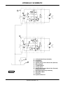
Operator Station Controls
c
• Keep the nozzle in contact with the rim of the fuel tank or container
opening at all times until the fueling is complete. Do not use a nozzle lockopen device.
• Never overfill fuel tank. Replace fuel tank cap and tighten securely.
• Replace all fuel container caps securely after use.
• For gasoline engines, do not use gas with methanol. Methanol is harmful
to your health and to the environment.
Handling Waste Product and Chemicals
• Waste products, such as, used oil, fuel, coolant, brake fluid, and
batteries, can harm the environment and people:
• Do not use beverage containers for waste fluids - someone may drink
from them.
• See your local Recycling Center or authorized dealer to learn how to
recycle or get rid of waste products.
• A Material Safety Data Sheet (MSDS) provides specific details on
chemical products: physical and health hazards, safety procedures, and
emergency response techniques. The seller of the chemical products
used with your machine is responsible for providing the MSDS for that
product.
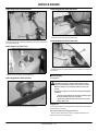
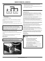
MX20138
Picture Note:
A-Speed Control Bar Lock
Operating
B-Speed Control Bar
Daily Operating Checklist
C-Left Motion Control Lever
Make sure all necessary guards and shields are safely and securely
attached. Check for loose, missing, or damaged parts.
Remove mower deck belt shields. Clean grass and debris from belt
area.
E-Hydrostatic Oil Reservoir Cap and Dipstick
F-Ignition Key Switch
G-Fuel Tank Cap
Remove grass and debris from machine and mower deck.
Remove grass and debris from operator station foot plate, pump drive
belt compartment, hydraulic pump and pump mounting plate.
Test park brake.
D-Right Motion Control Lever
H-PTO Switch
I-Optional Light Switch Location
J-Hourmeter
Operating - 7
OPERATING
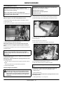
Mounting and Dismounting Machine Safely
K-Choke
c
L-Throttle Lever
M-Park Brake Lever
Mower Deck Controls
c
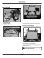
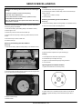
MX20095
1. Step on operator’s platform (A) at the rear of machine to mount the
machine.
2. Park machine safely. (See Parking Safely in the SAFETY section.)
MX20093
A-Mower Deck Lift Levers
3. Step off operator’s platform to dismount machine.
4. Keep operator’s platform and suspension springs clean and free of
debris.
B-Height-of-Cut (HOC) Pin
Miscellaneous Controls
Raising and Lowering Thigh Pad
c
1. Park machine safely. (See Parking Safely in the SAFETY section.)
c
MX20094
A-Free-Wheeling Valves
MX20096
2. Raise and lower thigh pad (A) as required.
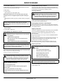
Adjusting Mower Deck Cutting Height
The mower deck height adjustment consists of seven different cutting
heights. The cutting heights range from 38-114 mm (1-1/2-4-1/2 in.) in 13
mm (1/2 in.) increments.
c
CAUTION: Avoid injury! Before adjusting cutting height,
stop engine and lock the park brake.
1. Park machine safely. (See Parking Safely in the SAFETY section.)
2. Disengage PTO.
Operating - 8
OPERATING
3. Stop engine and lock park brake.
NOTE: Discharge chute raised for clarity.
c
c
MX20139
MX20099
2. Position right mower blade (A) (discharge side) perpendicular to
direction of travel.
4. Remove retaining ring (A) from HOC pin (B).
5. Push down on deck lift lever (C).
6. Remove HOC pin.
NOTE: Use a short ruler or a leveling gauge to check the mower
blade level.
7. Place HOC pin in desired height hole (D).
3. Measure distance (B) from outside blade tip to the ground.
8. Release deck lift lever (C).
4. Position left mower blade perpendicular to direction of travel.
9. Install retaining ring (A) in HOC pin (B).
5. Measure from outside blade tip to the ground.
• The difference between both measurements should be no greater than
3 mm (1/8 in.).
10. Repeat procedure for opposite side.
Leveling Mower Deck
6. If side-to-side level is not within the tolerance, an adjustment is
necessary.
c
CAUTION: Avoid injury! Rotating blades are dangerous.
Before adjusting or servicing mower:
Disconnect spark plug wire(s) or battery negative (-) cable
to prevent engine from starting accidently.
Adjusting Level (Side-to-Side)
NOTE: When adjusting U-bolts, maintain a minimum clearance of 3
mm (1/8 in.) between mower deck and stop pads.
c
Always wear gloves when handling mower blades or
working near blades.
NOTE: Mower deck anti-scalp wheels should not contact the ground.
1. Park machine safely. (See Parking Safely in the SAFETY section.)
2. Inflate tires to the correct pressure.
3. Inspect mower blades for:
• Blade sharpness.
• Blade damage.
• Bent blades.
Checking Level (Side-to-Side)
MX20099
NOTE: Mower deck anti-scalp wheels should not contact the ground.
1. Adjust mower deck to 76 mm (3 in.) cutting height position.
Adjust four U-bolts (C) (two on each side of deck) until deck is within 3 mm
(1/8 in.) of level from side-to-side.
Operating - 9
OPERATING
c
c
MX20100
a. Loosen jam nuts (D) and adjust nuts (E) on each U-bolt until side-to
side level is reached.
MX20099
1. Loosen jam nut (H) on both deck lift assist rods.
2. Adjust front-to-rear mower level:
b. Tighten jam nuts (D).
• Turn nut (I) on both sides clockwise to raise front of mower deck, or
counterclockwise to lower front of mower deck.
Checking Level (Front-to-Rear)
1. Set height-of-cut (HOC) to the 76 mm (3 in.) cutting height position.
3. Verify that the adjustment on right and left sides is equal.
NOTE: The height of the rear blade tip should be between 3-6 mm (1/
8-1/4 in.) higher than the front blade tip.
4. Tighten jam nuts (H).
c
5. Check front-to-rear mower level.
Checking and Adjusting Cutting Height
c
CAUTION: Avoid injury! Rotating blades are dangerous.
Before adjusting or servicing mower:
•Disconnect spark plug wire(s) or battery negative (-)
cable to prevent engine from starting accidentally.
•Always wear gloves when handling mower blades or
working near blades.
Checking Overall Cutting Height
1. Inflate tires to correct pressure.
MX20122
2. Position right mower blade (F) (discharge side) parallel to the direction
of travel.
3. Measure distance (G) from front blade tip to the ground.
2. Lower mower deck to the 76 mm (3 in.) cutting height.
3. Position right mower blade (discharge side) parallel to the direction of
travel.
4. Measure from the front of the blade tip to the ground.
4. Turn blade 180° and measure from rear blade tip to the ground.
5. If the front-to-rear level is not within the tolerance, an adjustment is
necessary.
5. If blade tip height is not within 73-79 mm (2-7/8-3-1/8 in.), an
adjustment is needed.
Adjusting Level (Front-to-Rear)
c
IMPORTANT: Avoid damage: Adjust the left and right deck lift
assist rods equally.
NOTE: Adjust side-to-side mower level before adjusting front-to-rear
level.
Adjust both sides of the mower deck equally.
All lift chains must remain taut.
Operating - 10
OPERATING
Testing Safety Systems
Adjusting Overall Cutting Height
c
NOTE: When adjusting U-bolts, maintain a minimum clearance of 3
mm (1/8 in.) between mower deck and stop pads.
CAUTION: Avoid injury! Engine exhaust fumes contain
carbon monoxide and can cause serious illness or death.
Adjust both sides of the mower deck equally.
Move the machine to an outside area before running the
engine.
All lift chains must remain taut.
c
Do not run an engine in an enclosed area without adequate
ventilation.
• Connect a pipe extension to the engine exhaust pipe to
direct the exhaust fumes out of the area.
• Allow fresh outside air into the work area to clear the
exhaust fumes out.
The safety systems installed on your machine should be checked before
each machine use. Be sure you have read the machine operator manual
and are completely familiar with the operation of the machine before
performing these safety system checks.
MX20099
1. Adjust four U-bolts (A) (two on each side of deck) until blade tip height is
within 73-79 mm (2-7/8-3-1/8 in.) of the 76 mm (3 in.) setting.
Use the following checkout procedures to check for normal operation of
machine.
cIf there is a malfunction during one of these procedures, do not operate
machine. See your authorized dealer for service.
Perform these tests in a clear open area. Keep bystanders away.
Adjusting Mower Deck Anti-Scalp Wheels
NOTE: The flattest cut can be achieved by having all anti-scalp
wheels adjusted off the ground. Check anti-scalp wheel adjustments
each time the mower deck cutting height is changed.
It is recommended that all anti-scalp wheels be kept off the ground to
minimize scuffing.
1. Inflate tires to correct pressure.
Testing PTO Switch
1. Stand on operator’s platform with motion control levers in the neutral
position.
2. Lock park brake.
3. Pull PTO switch up to engage.
4. Turn key switch to the start position.
2. Adjust mower deck to desired cutting height.
Result: The engine must not crank.
c
Testing Park Brake Switch
1. Push PTO switch down to disengage.
2. Unlock park brake.
3. Turn key switch to the start position.
Result: The engine must not crank.
Testing Neutral Switch (Start)
1. Lock park brake.
2. Push PTO switch down to disengage.
3. Push one motion control lever forward.
MX15658
4. Turn key switch to the start position.
Result: The engine must not crank.
3. Adjust anti-scalp wheel (A) to one of three positions (D).
• Remove screw (E), nut (C) and washer (B).
Testing Neutral Switch (Run)
• Adjust wheel up or down so it is approximately 6–13 mm (1/4–1/2 in.)
above mowing surface.
1. Lock park brake.
2. Push PTO switch down to disengage.
4. Install wheel with attaching hardware.
3. Start engine.
5. Adjust all wheels to the same height.
4. Push one motion control lever forward.
5. Repeat procedure using the other lever.
6. Repeat procedure pushing each motion control lever rearward.
Result: The engine must stop when either lever is moved from neutral
position.
c
c
Operating - 11
OPERATING
Testing Operator Presence Switch
Using Park Brake
NOTE: Ensure OPC switch bracket is depressed when standing on
operator’s station.
Locking Park Brake
c
1. Stand on operator’s platform with motion control levers in the NEUTRAL
position.
2. Start engine.
3. Unlock park brake.
4. Step completely off operator’s platform.
Result: The engine must stop.
NOTE: Ensure OPC switch bracket is depressed when standing on
operator’s station.
5. Stand on operator’s platform with motion control levers in the NEUTRAL
position and start engine.
c
MX20102
CAUTION: Avoid injury! Thrown objects can be dangerous.
Before operating the attachment:
Clear area of bystanders, especially children.
Raise park brake lever (A) to lock park brake.
Unlocking Park Brake:
Lower park brake lever (A) to unlock park brake.
Pick up objects which may be thrown by the attachment.
Using the PTO
6. Pull PTO switch up to engage.
Engage PTO:
7. Step completely off operator’s platform.
1. Stand on operator’s platform with motion control levers in the neutral
position.
Result: The engine must stop.
2. Start engine.
Testing the Park Brake
3. Release park brake.
c
4. Move throttle lever to the 1/2 to 3/4 fast position.
c
MIF
1. Stop machine on a 17° slope (30% grade) facing downhill. Stop the
engine and lock the park brake.
MX12854
2. Repeat procedure with machine facing uphill.
5. Pull PTO knob (A) up to engage mower deck.
Result: Park brake must hold the machine stationary. (Machine should
move no more that 61cm (24 in.) in one hour.) If machine moves more
than that, brakes need to be adjusted. See your authorized dealer or refer
to Adjusting Park Brake in the SERVICE STEERING AND BRAKES
section.
6. Move throttle lever forward to the fast position for mowing.
Disengage PTO:
1. Push PTO knob (A) down.
2. Set park brake.
Operating - 12
OPERATING
Using the Throttle
Neutral Position
c
c
MX12847
MX20091
• Push throttle lever (A) forward to the fast position (B) when mowing.
• Move throttle lever (A) to the half fast position (C) when starting and
warming the engine.
• Pull throttle lever (A) backward to the slow position (D) to idle engine. Do
not run engine at slow idle any longer than necessary for cooldown after
mowing.
Using the Hourmeter
Picture Note: Motion control levers (A) shown in the neutral
position.
• Machine speed, motion and direction can be controlled when the engine
is running and park brake is unlocked.
• Operator can exit the mower with the engine running when the park
brake is locked and the PTO switch is disengaged.
Forward and Reverse Motion:
NOTE: The machine is equipped with an electric start. The hourmeter
will continue to run with the key switch in the run position.
c
CAUTION: Avoid injury! Children or bystanders may be
injured by runover and rotating blades. Before traveling
forward or rearward:
c
• Carefully check the area around the machine.
• Disengage the mower before backing up.
1. Move throttle lever to the fast position.
2. Unlock park brake.
3. Push motion control levers forward to begin forward motion. The further
forward the control levers are moved, the faster the machine will travel.
• Forward speed range: 0–14.8 km/h (0–9.2 mph)
MX20091
• Hourmeter (A) shows number of hours the machine has been operated.
4. Pull both motion control levers rearward at the same time to begin
reverse motion.
•Reverse speed range: 0–6.4 km/h (0–4 mph)
• Use hourmeter and SERVICE INTERVAL section to determine when
machine needs service.
5. To stop motion, move both motion control levers forward or rearward
until the machine comes to a stop.
Using the Motion Control Levers
NOTE: The motion control linkages are adjustable. If adjustment is
required, see Checking and Adjusting Motion Control Linkages in
the SERVICE TRANSMISSION section.
The functions of the motion control levers are:
c
CAUTION: Avoid injury! Learn use of the motion control
levers and practice at half throttle until becoming proficient
and comfortable with the operation of the machine.
Do not move motion control levers from forward to reverse or
reverse to forward position rapidly. Sudden direction
changes could cause loss of control or damage the machine.
• Steering.
• Acceleration.
• Deceleration.
c
Operating - 13
OPERATING
Forward:
Gentle Right Turn:
c
c
MX12791
MX12788
• Push both motion control levers forward at the same time.
• Push left motion control lever further forward than the right motion control
lever.
Reverse:
Sharp Left Turn:
c
c
MX12792
MX12789
• Pull both motion control levers past center rearward at the same time.
• Push right motion control lever forward and pull left motion control lever
rearward at the same time.
Gentle Left Turn:
Sharp Right Turn:
c
c
MX12790
• Push right motion control lever further forward than the left motion control
lever.
MX12793
• Push left motion control lever forward and pull right motion control lever
rearward at the same time.
Operating - 14
OPERATING
Starting Engine
Engaging Mower
c
c
CAUTION: Avoid injury! Engine exhaust fumes contain
carbon monoxide and can cause serious illness or death.
CAUTION: Avoid injury! Clear mowing area of all bystanders
when operating this machine. Thrown objects could cause
serious injury or death.
Move the machine to an outside area before running the
engine.
Keep hands and feet away from blades and discharge
opening.
Do not run an engine in an enclosed area without adequate
ventilation.
Do not mow in reverse unless absolutely necessary.
• Connect a pipe extension to the engine exhaust pipe to
direct the exhaust fumes out of the area.
IMPORTANT: Avoid damage! To help prevent damage to PTO
clutch:
• Allow fresh outside air into the work area to clear the
exhaust fumes out.
• Do not engage PTO with throttle in the fast position.
1. Stand on operator’s platform.
1. Adjust mower deck to desired cutting height.
2. Lock park brake.
2. Start engine.
c
c
MX20091
MX20091
3. Put motion control levers (A) in the NEUTRAL position.
3. Move throttle lever (A) to the 1/2 to 3/4 fast position.
4. Push PTO switch knob (B) down to disengage PTO.
4. Unlock park brake.
5. Move throttle lever (C) to set engine speed at the 1/2 to 3/4 fast
position.
NOTE: In cold weather or with a new machine, allow engine to reach
operating temperature before engaging PTO to prevent engine from
stalling.
6. Position choke knob (D):
• Cold engine: Pull knob up to the CHOKE position.
5. Pull PTO knob (B) up to engage mower deck.
• Warm/Hot engine: If necessary, pull knob up to the CHOKE position.
6. Move throttle lever to the fast position (C).
7. Turn key switch (E) to the START position.
8. Release key to the RUN position when engine starts.
9. With engine started:
• Push choke knob to the OFF position.
• Move throttle lever to the FAST position.
NOTE: The travel speed and turn rate will vary with the amount that
the motion control levers are moved.
7. Push motion control levers (D) forward slowly. Mow at a safe travel
speed.
Stopping the Engine
c
• Unlock park brake.
IMPORTANT: Avoid damage! To help prevent engine backfiring,
throttle lever should be set at the half-speed position prior to
stopping the engine.
Do not stop engine when mower is on a slope of more than 30
degrees for an extended period of time. Oil may run through valve
train into carburetor and muffler.
1. Lock park brake.
2. Reduce engine speed to half-throttle.
3. Turn key switch to STOP position (C).
4. Remove key.
Operating - 15
OPERATING
Using Pump Free-Wheel Valves
3. Stop engine and lock park brake.
c
4. Remove key.
CAUTION: Avoid injury! With the free-wheeling valve open,
the machine will have unrestricted motion.
• The machine may free-wheel out of control if the freewheeling valve is opened with the machine on an incline.
• Park the machine on a level surface before opening the
free-wheeling valve.
5. Fasten machine to trailer with heavy-duty straps, chains or cables. Both
front and rear straps must be directed downward and outward from
machine.
Mowing Tips
• Mow grass with throttle lever in the full fast position.
• Cut grass when it is dry.
• Keep mower deck and discharge chute clean.
IMPORTANT: Avoid Damage! Transmission damage may occur if
the machine is towed or moved incorrectly:
• Mow with sharp blades.
• Properly level mower deck for a smooth cut.
• Move machine by hand only.
• Mow grass high and often.
• Do not use another vehicle to move machine.
• Use a travel speed that fits the conditions:
• Do not tow machine.
• Mow tall or wet grass twice. Cut grass at half desired height – then cut
at desired height.
NOTE: The pump free-wheel valves must be turned fully clockwise
(closed) during normal machine operation.
• Travel slow when mowing tall, thick or wet grass.
When the machine needs to be moved without starting the engine, use the
pump free-wheel valves:
• Avoid damaging grass by slipping or skidding machine drive wheels.
Practice smooth control lever movements.
1. Lock park brake.
• When performing sharp turns, do not allow inside machine drive wheel
to stop and twist on grass.
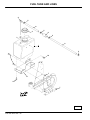
NOTE: The pumps (A) are located in the back of the machine, behind
the rear shield (B).
c
Mowing Travel Speeds
Use slow travel speeds for:
• Slopes.
• Trimming.
• Close quarters.
• Tall grass.
Use faster travel speeds for:
• Normal mowing on level ground.
Dismounting to Inspect Mower
c
MX20094
CAUTION: Avoid injury! Help prevent serious injury. Keep
hands and feet away from blades and the discharge opening.
2. Turn both pump free-wheel valves (C) counterclockwise approximately
one full turn (open position).
• Do not step on either side of the mower deck when
mounting and dismounting the machine. Mount and
dismount the machine using the front foot plate.
3. Unlock park brake.
4. Push machine to desired location. Due to hydraulic system drag,
machine will move slowly.
1. Park machine on a hard, level surface.
5. Turn pump free-wheel valves (C) on both pumps one full turn clockwise
(closed position). Tighten valves to 11 N•m (100 lb-in.).
2. Disengage PTO.
3. Move motion control levers to the neutral position.
6. Lock park brake.
4. Lock park brake.
Transporting Machine on a Trailer
Use a heavy-duty trailer to transport your machine. Trailer must have
signs and lights required by law.
5. Stop engine and remove key. Wait for mower blades to stop turning
before leaving operator’s position.
c
CAUTION: Avoid injury! Use extra care when loading or
unloading the machine into a trailer or truck.
• Close fuel shut-off valve, if your machine is equipped.
1. Raise mower deck to the transport position.
2. Drive machine onto a trailer.
Operating - 16
SERVICE INTERVALS
Every 500 Hours
Service Intervals
• Change hydraulic oil and filter.
Servicing Your Machine
Yearly
c
IMPORTANT: Avoid Damage! Operating in extreme conditions
may require more frequent service intervals:
• Change fuel filter.
• Engine components may become dirty or plugged when
operating in extreme heat, dust or other severe conditions.
• Change engine oil and filter at least once per season.
• Engine oil may lose efficiency if vehicle is operated constantly at
slow or low engine speeds or with frequent short trips.
Please use the following timetables to perform routine maintenance on
your machine.
Servicing Engine
• Clean battery.
• Change hydraulic oil and filter at least once per season.
• Replace spark plugs.
Service Lubrication
Grease
See engine manufacturer’s owner’s manual provided with your machine
for engine service information.
c
IMPORTANT: Avoid Damage! The recommended grease is
effective within an average air temperature range of -29 to 135
degrees C (-20 to 275 degrees F).
Break-In (After First 10 Hours)
• If operating outside that temperature range, contact your
servicing dealer for a special-use grease.
• Check air pressure in tires.
• Check wheel bolt torque.
• Check and adjust park brake.
Use a general all-purpose grease with an NLGI grade No.2 rating.
• Change engine oil and filter.
Wet or high speed conditions may require use of a special-use grease.
Contact your Servicing dealer for information.
• Check mower deck drive belt tension.
• Check hydraulic pump drive belt.
Lubricating Front Caster Spindles and Wheels
c
• Check transmission neutral adjustment.
CAUTION: Avoid injury! Fingers or loose clothing can get
caught in rotating parts. Stop engine and wait for all moving
parts to stop before servicing.
Every 40 Hours
• Check air pressure in tires.
• Check wheel bolt torque.
c
• Check and adjust park brake.
• Change engine oil and filter.
• Check foam and paper air cleaner elements.
• Clean engine shrouds as needed.
• Lubricate front caster spindles and wheels.
• Lubricate mower deck lift pivot tubes.
• Lubricate mower deck idler pivot.
• Lubricate mower deck push arms.
• Check mower deck drive belt tension.
MX15286
• Lubricate hydraulic pump idler pivot.
• Check hydraulic pump drive belt.
• Lubricate two spindle grease fittings (A) and two wheel grease fittings
(B).
• Check hydraulic fluid level.
• If operating machine in extremely dusty or dirty conditions:
• Clean behind engine shrouds and exposed fins.
• Remove screws on blower fan screen and clean behind.
Every 100 Hours
• Lubricate mower deck spindles.
• Clean and gap spark plugs.
• Check hydraulic pump drive belt.
• Clean behind engine shrouds and exposed fins.
• Remove screws on blower fan screen and clean behind.
Service Intervals - 17
SERVICE ENGINE
Lubricating Deck Lift Pivot Points
Lubricating Mower Deck Idler Pivot
c
c
MX20106
• Lubricate one deck idler pivot grease fitting (A).
MX20104
• Lubricate two front deck lift pivot grease fittings (A) and two rear deck lift
pivot grease fittings (B).
Lubricating Mower Deck Push Arms
c
Lubricating Pump Idler Pivot
c
MX20107
• Lubricate two push arm grease fittings (A), one located on each side of
the machine.
MX15095
• Lubricate one pump idler pivot grease fitting (A).
Service Engine
Lubricating Mower Deck Spindles
Avoid Fumes
c
c
CAUTION: Avoid injury! Engine exhaust fumes contain
carbon monoxide and can cause serious illness or death.
Move the machine to an outside area before running the
engine.
Do not run an engine in an enclosed area without adequate
ventilation.
• Connect a pipe extension to the engine exhaust pipe to
direct the exhaust fumes out of the area.
• Allow fresh outside air into the work area to clear the
exhaust fumes out.
MX15287
• Lubricate three mower deck spindle grease fittings (A).
Engine Oil
Use oil viscosity based on the expected air temperature range during the
period between oil changes.
Use oil that meets the following specification:
• See the engine manufacturer’s owner’s manual provided with your
machine for the correct specifications.
Service Engine - 18
SERVICE ENGINE
Checking Engine Oil Level
c
IMPORTANT: Avoid Damage! Change the oil more often if the
machine is used in extreme conditions:
IMPORTANT: Avoid Damage! Failure to check the oil level
regularly could lead to serious engine problems if oil level is low:
Extremely dusty conditions.
Check oil level before operating.
Frequent slow or low-speed operation.
Keep oil level between the FULL and the ADD marks.
Check oil level when engine is stopped, level, and is cooled so oil
has had time to drain into the sump.
Frequent short trips.
1. Clean area around dipstick cap and filter.
NOTE: Check oil twice a day if you run engine over 4 hours in a day.
2. Start engine and run until it reaches normal operating temperature.
Make sure engine is cool when checking engine oil level.
3. Park machine safely. (See Parking Safely in the SAFETY section.)
1. Park machine safely. (See Parking Safely in the SAFETY section.)
c
2. Allow engine to cool.
3. Clean area around dipstick to prevent debris from falling into crankcase.
c
MX201858
4. Put oil drain pan under drain tube.
5. Remove plug (A).
MX20155
4. Remove dipstick (A). Wipe with a clean cloth.
6. Allow oil to drain into an oil drain pan.
7. After oil drains, install and securely tighten drain plug (A).
NOTE: Allow dipstick cap to rest on threads of filler tube when
checking oil level. Do not tighten dipstick cap when checking oil
level.
c
5. Install dipstick and allow the cap to rest on the threads of the tube. Do
not tighten the cap.
c
IMPORTANT: Avoid Damage! To prevent extensive engine wear or
damage, always maintain the proper engine oil level. Never
operate the engine with the oil level below the add mark or over
the full mark.
6. Remove dipstick and check oil level on dipstick. Oil must be between
the ADD and FULL marks.
NOTE: Refer to engine manufacturers operating manual for correct
type and grade of oil.
• If oil is low, add oil to bring oil level no higher than the FULL mark on
dipstick.
• If oil level is above the FULL mark, drain to proper level.
MX20149
8. Turn oil filter (B) counterclockwise to remove.
9. Apply a film of clean engine oil to gasket of new filter.
c
IMPORTANT: Avoid Damage! Do not use wrench to tighten oil
filter.
7. Install and tighten dipstick.
Changing Engine Oil and Filter
10. Install filter. Turn filter clockwise until gasket makes contact with
mounting surface. Tighten 1/2 to 3/4 turn after gasket contact.
c
CAUTION: Avoid injury! Touching hot surfaces can burn
skin. The engine, components, and fluids will be hot if the
engine has been running. Be cautious and wear protective
clothing when servicing or working near a hot engine and
components.
11. Raise thigh pad.
12. Remove dipstick cap.
NOTE: Refer to engine manufacturers operating manual for correct
type and grade of oil.
13. Add approximately 1.7 L (1.75 qt) of oil.
Service Engine - 19
SERVICE ENGINE
14. Insert dipstick. Tighten cap.
operating machine in dusty conditions.
15. Start engine and run at slow throttle for approximately two minutes.
Check for leaks around filter and drain valve.
Check and clean air filter elements at the intervals recommended in the
Service Intervals section. See the engine manufacturer’s owner’s manual
provided with your machine for the complete procedure.
16. Stop engine.
Checking Spark Plug
17. Check oil level:
c
• Remove dipstick cap. Wipe dipstick clean.
CAUTION: Avoid injury! Touching hot surfaces can burn
skin. The engine, components, and fluids will be hot if the
engine has been running. Allow the engine to cool before
servicing or working near the engine and components.
NOTE: Allow dipstick cap to rest on threads of filler tube when
checking oil level. Do not tighten dipstick cap when checking oil
level.
• Insert dipstick and allow cap to rest on threads of filler. Do not tighten
cap.
c
IMPORTANT: Avoid Damage! To prevent extensive engine wear or
damage, always maintain the proper engine oil level. Never
operate the engine with the oil level below the add mark or over
the full mark.
• Remove dipstick. Add oil as needed to bring level to the full mark
without overfilling.
18. Insert dipstick. Tighten cap.
Check spark plugs at the intervals recommended in the Service Intervals
section. See the engine manufacturer’s owner’s manual provided with
your machine for the complete procedure.
Cleaning Engine Oil Cooler - Kohler Engines
Keep engine oil cooler fins clear of debris to ensure proper cooling. See
the engine manufacturer’s owner’s manual provided with your machine for
the complete procedure.
Adjusting Carburetor
Carburetor is calibrated by the engine manufacturer and is not adjustable.
Cleaning Engine Air Intake Screen and Fan
c
CAUTION: Avoid injury! Compressed air can cause debris to
fly a long distance.
Clear work area of bystanders.
Wear eye protection when using compressed air for
cleaning purposes.
Reduce compressed air pressure to 210 kPa (30 psi).
If engine is operated at altitudes above 1829 m (6,000 ft), some
carburetors may require a special high altitude main jet. See your
authorized dealer.
If engine is hard to start or runs rough, check the TROUBLESHOOTING
section of this manual.
Possible engine surging will occur at high throttle with transmission in “N”
neutral and mower engagement lever disengaged. This is a normal
condition due to the emission control system.
After performing the checks in the troubleshooting section and your
engine is still not performing correctly, contact your authorized dealer.
c
IMPORTANT: Avoid damage! An obstructed air intake screen can
cause engine damage due to overheating. Keep air intake screen
and other external surfaces of the engine, including cooling fins,
clean at all times to allow adequate air intake.
Replacing Fuel Filter
c
CAUTION: Avoid injury! Fuel vapors are explosive and
flammable:
Keep air intake screens and engine cooling fins clear of debris to ensure
proper cooling. See the engine manufacturer’s owner’s manual provided
with your machine for the complete procedure.
• Do not smoke while handling fuel.
• Keep fuel away from flames or sparks.
• Shut off engine before servicing.
Checking and Cleaning Air Filter Elements
c
• Cool engine before servicing.
• Work in a well-ventilated area.
CAUTION: Avoid injury! Touching hot surfaces can burn
skin. The engine, components, and fluids will be hot if the
engine has been running. Allow the engine to cool before
servicing or working near the engine and components.
c
IMPORTANT: Avoid damage! Dirt and debris can enter the engine
through a damaged filter element:
• Clean up spilled fuel immediately.
IMPORTANT: Avoid Damage! When installing a new fuel filter, the
filter arrow must be pointed in the direction of the fuel flow.
1. Park machine safely. (See Parking Safely in the SAFETY section.)
• Do not wash paper element.
• Do not attempt to clean paper element by tapping against
another object.
2. Allow engine to cool.
• Do not use pressurized air to clean element.
• Replace element only if it is very dirty, damaged or the seal is
cracked.
NOTE: It may be necessary to check the air filter more frequently if
Service Engine - 20
SERVICE TRANSMISSION
NOTE: Do not tighten dipstick cap when checking oil level.
c
4. Insert dipstick into reservoir filler neck (B). Do not tighten cap.
5. Remove dipstick. Check oil level on dipstick. Oil level should be in
crosshatch area between ADD and FULL marks.
• If oil is low, add oil to bring oil level no higher than FULL mark on
dipstick.
• If oil is above FULL mark, drain oil to proper level.
6. Insert dipstick. Tighten cap.
Changing Hydraulic Oil and Filter
c
CAUTION: Avoid injury! Escaping fluid under pressure can
penetrate the skin causing serious injury. Avoid the hazard
by relieving pressure before disconnecting hydraulic or other
lines. Tighten all connections before applying pressure.
Search for leaks with a piece of cardboard. Protect hands and
body from high pressure fluids.
MX20149
3. Slide hose clamps (A) away from fuel filter (B).
4. Place drain pan under hoses to catch any fuel that may be left in the
hoses.
5. Disconnect hoses from fuel filter (B).
Use caution when filling and draining hydraulic oil. During
periods of machine operation the hydraulic oil reservoir can
get hot. Allow engine and oil reservoir to cool before
servicing.
6. Install new fuel filter (B).
• Make sure fuel filter (B) is installed with arrow pointing in direction of
fuel flow.
7. Connect hoses to new fuel filter (B).
IMPORTANT: Avoid Damage! Contamination of hydraulic fluid
could cause transmission damage or failure. Do not open oil
reservoir cap unless absolutely necessary.
8. Install hose clamps (A).
9. Start engine and check for fuel leaks.
Severe or unusual conditions may require a more frequent
service interval.
Service Transmission
Hydraulic Oil
1. Park machine safely. (Refer to Parking Safely in the SAFETY section.)
Use only 5W-50 or 15W-50 all synthetic oil.
2. Allow engine and hydraulic oil reservoir to cool.
c
Checking Hydraulic Oil Level
c
IMPORTANT: Avoid Damage! Check oil level in reservoir tank
when oil is cold.
Do not overfill oil reservoir tank. Oil will expand during operation
and could overflow.
1. Park machine safely. (Refer to Parking Safely in SAFETY section.)
c
MX13362
3. Clean area around reservoir dipstick cap and oil filter.
4. Turn metal cap (A) on bottom of hydraulic reservoir counterclockwise to
remove.
5. Allow hydraulic oil to drain into a drain pan with a capacity of at least
3.8L (1.0 gal).
6. Turn oil filter (B) counterclockwise to remove.
MX20114
2. Clean area around reservoir dipstick cap (A).
3. Remove dipstick cap (A). Wipe dipstick clean.
7. Apply a film of clean hydraulic oil to gasket of new filter.
8. Install new filter. Turn filter clockwise until gasket makes contact with
mounting surface. Tighten 1/2 to 3/4 turn after gasket contact.
9. Remove dipstick cap from hydraulic reservoir filler neck.
Service Transmission - 21
SERVICE TRANSMISSION
Checking and Replacing Pump Traction Drive Belt
c
IMPORTANT: Avoid Damage! Do not add oil beyond FULL mark.
Oil capacity after draining may be less than dry fill capacity.
Check oil level before filling completely.
c
CAUTION: Avoid injury! Fingers or loose clothing can get
caught in rotating parts. Stop engine and wait for all moving
parts to stop before servicing.
NOTE: Dry fill capacity for hydraulic system is 3.1L (3.3 qt).
10. Fill oil reservoir with approximately 1.9L (2 qt) of oil.
NOTE: The traction drive belt will not require a tension adjustment.
Belt is self-adjusted using a spring tensioner.
11. Insert dipstick. Tighten cap.
12. Start engine.
Checking Traction Drive Belt:
13. Move throttle lever to 1/2 to 2/3 position.
1. Park machine safely. (See Parking Safely in the SAFETY section.)
14. Unlock park brake.
c
c
CAUTION: Avoid injury! Help prevent serious bodily injury.
Remain alert to other people and the surroundings when
operating the machine.
15. Cycle motion control levers forward and rearward several times.
Check for leaks around filter.
16. Stop engine. Check oil level. Add oil as necessary to bring oil level to
FULL mark on dipstick.
Cleaning Hydraulic Oil Pump Cooling Fins
c
CAUTION: Avoid injury! Compressed air can cause debris to
fly a long distance.
• Clear work area of bystanders.
MX20126
2. Remove four cap screws (A).
3. Remove rear shield (B).
• Wear eye protection when using compressed air for
cleaning purposes.
c
• Reduce compressed air pressure to 210 kPa (30 psi).
IMPORTANT: Avoid Damage! To ensure proper cooling, keep the
cooling fins clean at all times. Operating the machine with
obstructed cooling fins could cause damage due to overheating.
1. Park machine safely. (See Parking Safely in the SAFETY section.)
c
MX20111
4. Inspect belt (C) through frame openings (D) for excessive wear,
damage or stretching.
Removing Traction Drive Belt:
1. Park machine safely. (See Parking Safely in the SAFETY section.)
2. Remove mower deck drive belt. (See Replacing Mower Deck Drive Belt
in the SERVICE MOWER section.)
MX20126
2. Remove four cap screws (A).
3. Remove rear shield (B) to access hydraulic pumps (C).
4. Clean hydraulic oil cooling fins on each hydraulic pump with a rag,
brush or compressed air.
5. Clean area around hydraulic pumps and frame.
Service Transmission - 22
SERVICE TRANSMISSION
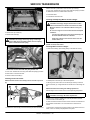
traction drive belt is positioned in front of anchor cap screw (F).
c
2. Insert 1/2 in. breaker bar into hole (C) and rotate idler pulley (D) forward
for additional clearance to install traction drive belt.
3. Install rear shield.
4. Install mower deck drive belt.
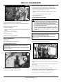
Checking and Adjusting Motion Control Linkages
c
CAUTION: Avoid injury! Engine exhaust fumes contain
carbon monoxide and can cause serious illness or death.
Move the machine to an outside area before running the
engine.
MX20126
Do not run an engine in an enclosed area without adequate
ventilation.
3. Remove four cap screws (A).
Connect a pipe extension to the engine exhaust pipe to
direct the exhaust fumes out of the area.
4. Remove rear shield (B).
c
CAUTION: Avoid injury! Tensioning spring is under high
tension. Wear gloves and safety glasses, and use a spring
puller to install and remove spring.
Allow fresh outside air into the work area to clear the
exhaust fumes out.
NOTE: Check and adjust motion control linkages with the machine
parked on a hard, level surface.
c
Checking Motion Control Linkages:
1. Park machine safely. (See Parking Safely in the SAFETY section.)
c
MX20167
Picture Note: Traction drive belt idler pulley bottom view.
5. Insert 1/2 in. breaker bar into hole (C) and rotate idler pulley (D) forward
to ease tension on traction drive belt.
6. Remove traction drive belt (E).
Installing Traction Drive Belt:
MX20109
NOTE: Install the traction drive belt (E) in front of anchor cap screw
(F).
c
D
G
2. Rotate speed control bar (A) to full forward position.
3. With engine off, move motion control levers (B) until they contact the
speed control bar (A). A slight deflection should be seen in the linkage rod
(C).
NOTE: Check machine tracking after making adjustments.
Start the engine and run until it reaches normal operating temperature.
c
CAUTION: Avoid injury! Be aware of bystanders.
C
F
5. Stand on the operator’s platform and, with the park brake released,
move the motion control levers (B).
G
6. Observe wheel movement as motion control levers are moved back and
forth. Wheels should travel in the correct direction as the levers are
moved.
MX20168
1. Install traction drive belt (E) on drive sheaves (G) as shown. Ensure that
7. Move motion control levers to neutral position. If rear wheels continue to
rotate, a return to neutral (RTN) adjustment is required.
Service Transmission - 23
SERVICE TRANSMISSION
Adjusting Motion Control Return to Neutral (RTN) Linkages:
c
CAUTION: Avoid injury! Fingers or loose clothing can get
caught in rotating parts. Stop engine and wait for all moving
parts to stop before servicing.
NOTE: Check and adjust transmission tracking on a hard, level
surface.
Checking Transmission Tracking:
1. Check and adjust motion control linkages. See Checking and Adjusting
Motion Control Linkages in the SERVICE TRANSMISSION section.
1. Stop engine.
2. Start engine and run until it reaches normal operating temperature.
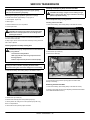
2. Lock park brake.
3. Move machine to an open, level area for operation.
3. Lift machine with a safe lifting device centered under rear tire support
frame.
c
4. Start the machine with motion control levers in neutral.
5. Stand on the operator’s platform and release park brake.
6. If rear wheels rotate when motion control levers are in neutral, a neutral
adjustment is required.
7. Stop engine.
c
MX20109
4. Drive machine forward, pushing both control levers (A) all the way to
speed control bar (B).
5. If machine does not drive in a straight line, an adjustment is required.
Adjusting Transmission Tracking:
MX20161
Picture Note: Side frame removed for picture clarity.
8. Slightly loosen cap screw (A) to allow rotation of neutral return plate.
• If wheel is rotating forward, rotate neutral return plate counterclockwise
until wheel rotation stops.
• If wheel is rotating in reverse, rotate neutral return plate clockwise until
wheel rotation stops.
1. Adjust appropriate control rod swivel (C) located on each side of
machine.
• If machine tracks to the right, remove spring pin (D) and rotate left
control rod swivel one turn clockwise. Install spring pin (D).
• If machine tracks to the left, remove spring pin (D) and rotate right
control rod swivel one turn clockwise. Install spring pin (D).
9. Tighten cap screw (A).
2. Check transmission tracking again and adjust as required until machine
drives in a straight line.
10. Recheck neutral. If wheels continue to rotate, readjust.
Adjusting Forward and Reverse Speeds
11. With the engine running, operate the motion control levers to verify
adjustment.
Adjusting Forward Speed:
Park machine safely. (See Parking Safely in the SAFETY section.)
• If engine will not crank over after adjustments are made, adjust the
neutral switch.
Checking and Adjusting Transmission Tracking
c
CAUTION: Avoid injury! Engine exhaust fumes contain
carbon monoxide and can cause serious illness or death.
Move the machine to an outside area before running the
engine.
Do not run an engine in an enclosed area without adequate
ventilation.
• Connect a pipe extension to the engine exhaust pipe to
direct the exhaust fumes out of the area.
• Allow fresh outside air into the work area to clear the
exhaust fumes out.
Service Transmission - 24
SERVICE STEERING & BRAKES
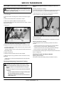
4. Tighten nuts (A).
c
Service Steering & Brakes
Adjusting Park Brake
Testing Park Brake:
1. Inflate tires to correct pressures.
c
MX20115
Picture Note: Arrow shows direction of speed control bar (A)
movement when decreasing forward speed.
2. Loosen lock lever (B) on speed control bar (A).
• To decrease forward speed, pull speed control bar (A) toward the
operator’s station.
• To increase forward speed, push speed control bar (A) forward (away
from operator’s station).
MX12874
2. Stop machine on a maximum 17° slope.
3. Lock park brake.
3. Tighten lock lever (B).
• A properly adjusted park brake must prevent the drive wheels from
turning.
Adjusting Reverse Speed:
• If the drive wheels turn, a brake adjustment will be necessary.
1. Park machine safely. (See Parking Safely in the SAFETY section.)
2. Loosen jam nut (C) on cap screw (D) on each side of machine.
Adjusting Park Brake:
• To decrease reverse speed, turn cap screw (D) counterclockwise.
1. Park machine safely. (Refer to Parking Safely in the SAFETY section.)
• To increase reverse speed, turn cap screw (D) clockwise.
2. Unlock park brake.
c
3. Tighten jam nut (C) on cap screw (D) on each side of machine.
Adjust Neutral Switch
c
MX20116
3. Loosen jam nut (A).
MX20161
Picture Note: Side frame removed for picture clarity.
1. Park machine safely. (See Parking Safely in the SAFETY section.)
4. Remove hair pin and washer (B).
5. Turn brake linkage rod (C) in one-turn increments clockwise to increase
braking force; counterclockwise to decrease braking force.
6. Install hair pin and washer (B).
2. Loosen nuts (A).
7. Tighten jam nut (A).
3. Adjust neutral switch (B).
• If neutral switch sensitivity needs to be increased, adjust switch (B)
down in slots.
8. Test park brake. Adjust again, if required.
c
• If neutral switch sensitivity needs to be decreased, adjust switch (B) up
in slots.
Service Steering & Brakes - 25
SERVICE MOWER
MX20117
Service Mower
2. Remove belt shield locking knobs (A).
Removing and Installing Mower Deck Shield
3. Remove belt shields (B) by sliding shield from mower deck stud.
c
Installing Belt Shields:
CAUTION: Avoid injury! Help prevent serious personal injury.
Do not operate the mower without the mower deck shield
installed.
1. Install belt shields (B) by sliding shield over mower deck stud.
2. Install belt shield locking knobs (A).
Removing Mower Deck Shield:
Adjusting Drive Belt Tension
1. Park machine safely. (See Parking Safely in the SAFETY section.)
1. Park machine safely.
2. Adjust mower deck to the 76 mm (3 in.) cutting height position.
c
3. Remove mower deck shield.
c
MX20105
2. Remove two knobs (A).
3. Lift shield (B) and pull forward to disengage from under tabs (C) on the
frame.
4. Remove mower deck shield (B).
MX20118
4. Measure length (C) of tension spring from inside of hook to inside of
hook. The spring should meaure 21.6 to 22.6 cm (8-1/2 in. to 8-7/8 in.).
• To add tension to spring: Loosen jam nut (B). Turn nut (A) clockwise.
Tighten jam nut (B).
Installing Mower Deck Shield:
1. Insert rear of shield (B) under tabs on frame and lower shield into
position.
2. Secure with knobs (A).
• To release tension from spring: Loosen jam nut (B). Turn nut (A)
counterclockwise. Tighten jam nut (B).
Replacing Mower Deck Drive Belt
Removing and Installing Mower Deck Drive Belt Shields
c
Removing Mower Deck Drive Belt:
1. Park machine safely. (See Parking Safely in the SAFETY section.)
CAUTION: Avoid injury! Help prevent serious personal injury.
Do not operate the mower without the belt shields installed.
2. Lower mower deck to the lowest cutting height position.
3. Remove mower deck shield.
Removing Belt Shields:
4. Remove both mower deck belt shields.
1. Park machine safely. (See Parking Safely in the SAFETY section.)
c
c
CAUTION: Avoid injury! Tensioning spring is under high
tension. Wear gloves and safety glasses, and use a spring
puller to install and remove spring.
Service Mower - 26
SERVICE MOWER
Installing Mower Deck Drive Belt:
c
NOTE: If necessary, see drive belt installation label on mower deck.
c
MX20118
5. Release mower deck drive belt tension by turning adjuster nut (A)
counterclockwise until two threads remain protruding through adjuster nut
(A).
MX20160
6. Disconnect idler spring (B) from idler arm (C) using a spring puller tool.
1. Install replacement drive belt (A) as shown on mower deck drive belt
label. Make sure drive belt is installed properly on PTO clutch sheave,
spindle sheaves and idler pulleys.
c
2. Tighten idler pulley retaining bolt to 34 N•m (25 lb-ft) ensuring idler
pulley belt is captured between idler pulley flange and belt guide.
c
MX20120
7. Loosen idler pulley retaining nut (D) just enough to allow idler pulley (E)
to tilt, allowing belt (F) to clear fixed belt guide (G).
8. Remove mower deck drive belt (F).
MX20118
3. Connect idler tension spring and adjust tension. The length (B) of the
tension spring should measure 21.6 to 22.6 cm (8-1/2 in. to 8-7/8 in.) from
inside of hook to inside of hook.
4. Install both mower deck belt shields.
5. Install mower deck shield.
6. Adjust mower deck to desired cutting height.
Checking for Bent Mower Blades
c
CAUTION: Avoid injury! Mower blades are sharp. Always
wear gloves when handling mower blades or working near
blades.
Replace blades if defective. Never straighten or weld them.
1. Park machine safely. (See Parking Safely in the SAFETY section.)
2. Raise mower to highest position to access blades.
Service Mower - 27
SERVICE MOWER
c
c
&
%
MX20122
Picture Note: Mower deck with side discharge used for illustration.
3. Measure distance (A) between blade tip and flat ground surface.
$
4. Rotate blade 180° and measure distance between other blade tip and
flat ground surface.
5. Install new blade if the difference between the two measurements is
more than 3 mm (1/8 in.).
1. Remove blade bolt (A), three 1/4 in. washers (B) and blade (C).
2. Install replacement blade:
6. Repeat for all blades.
• Blade wing must face toward top of mower deck.
Checking and Replacing Mower Blades
c
c
IMPORTANT: Avoid Damage! When installing the blade:
• Make sure the blade is properly seated on the spindle.
CAUTION: Avoid injury! Do not work near raised mower deck
unless it is safely supported.
• Make sure the concave side of the large washer faces towards
the blade.
Mower blades are sharp. Wrap blades or wear gloves when
servicing.
• Install blade bolt (A), blade (B) and three 1/4 in. washers (C).
Before performing any service function, wait for all moving
parts to stop turning.
Disconnect battery or remove spark plug wire before making
repairs.
• Tighten blade bolt to 163 N•m (120 lb-ft).
3. Lower machine.
4. Adjust mower deck to a desirable cutting height.
Sharpening Blades
IMPORTANT: Avoid Damage! When replacing mower blades,
always use genuine Great Dane Service Parts.
c
CAUTION: Avoid injury! Mower blades are dangerous!
NOTE: Only replace blades. Never straighten or weld them.
Always wear gloves while working on blades.
Checking Mower Blades
Always wear safety eye protection when grinding.
1. Park machine safely. (See Parking Safely in the Safety Section).
2. Raise the mower deck to the transport position (also the 12.7 cm [5 in.]
cutting height position).
• Sharpen blades with grinder, hand file, or electric blade sharpener.
c
3. Raise front of machine with a safe lifting device.
A
• Support with jack stands and/or wooden blocks.
4. Check mower blades:
• Mower blades should be sharp and free of any damage.
• Inspect blades; sharpen/balance or replace as necessary.
Replacing Mower Blades
B
MIF
Service Mower - 28
SERVICE ELECTRICAL
• Keep original bevel (A) when grinding.
c
• Blade should have 0.40 mm (1/64 in.) cutting edge (B) or less.
• Balance blades before installing.
Balancing Blades
c
CAUTION: Avoid injury! Mower blades are sharp. Always wear
gloves when handling mower blades or working near blades.
1. Clean blade.
c
c
2. Put blade on nail in a vise. Turn blade to horizontal position.
3. Check balance. If blade is not balanced, heavy end of blade will drop.
c
4. Grind bevel of heavy end. Do not change blade bevel.
c
Service Electrical
c
WARNING: Battery posts, terminals and related accessories contain lead
and lead components, chemicals known to the State of California to cause
cancer and reproductive harm. Wash hands after handling.
c
c
Service the Battery Safely
c
c
Service Electrical - 29
SERVICE ELECTRICAL
c
CAUTION: Avoid injury! Battery electrolyte contains sulfuric
acid. It is poisonous and can cause serious burns:
• Wear eye protection and gloves.
• Keep skin protected.
• If electrolyte is swallowed, get medical attention
immediately.
• If electrolyte is splashed into eyes, flush immediately
with water for 15-30 minutes and get medical attention.
• If electrolyte is splashed onto skin, flush immediately
with water and get medical attention if necessary.
The battery produces a flammable and explosive gas. The
battery may explode:
4. Loosen nut on front long carriage bolt (E).
5. Remove rear long carriage bolt (F) and nut.
• Do not smoke near battery.
6. Lift and slide battery (G) out from back of battery tray (H).
• Wear eye protection and gloves.
7. Inspect isolator pad (I). Replace as needed.
• Do not allow direct metal contact across battery posts.
Installing:
• Remove negative cable first when disconnecting.
1. Place isolator pad (I) in battery tray (H). Ensure that isolator pad is on
the bottom and sides of battery tray.
• Install negative cable last when connecting.
2. Install battery (G) in battery tray (H) with positive terminal in rear.
Checking the Battery (Sealed Batteries)
3. Install rear long carriage bolt (F) and nut. Do not overtighten.
NOTE: Do not attempt to open, add fluid or service battery. Any
attempt to do so will void warranty.
• Keep battery and terminals clean.
4. Tighten nut on long carriage bolt (E) to secure battery (G) in battery tray
(H). Do not overtighten.
5. Apply dielectric grease to terminals to prevent corrosion.
• Keep battery bolts tight.
6. Connect the positive (+) battery cable (D) and install cover (C).
• Keep small vent holes open.
7. Connect negative (-) battery cable (B) and install cover (A).
c
IMPORTANT: Avoid Damage! The battery comes fully charged. If
the machine is not used by the service expiration date indicated
on the battery, charge the battery.
Cleaning Battery and Terminals
1. Park machine safely. (See Parking Safely in the SAFETY section.)
2. Disconnect and remove battery.
Recharge, if necessary, at 6–10 amperes for 1 hour.
Removing and Installing Battery
3. Wash battery with solution of four tablespoons of baking soda to one
gallon of water. Be careful not to get the soda solution into the cells.
Removing:
4. Rinse the battery with plain water and dry.
1. Park machine safely. (See Parking Safely in the SAFETY section.)
5. Clean terminals and battery cable ends with wire brush until bright.
6. Apply general purpose grease or silicone spray to terminal to prevent
corrosion.
c
7. Install battery.
Using Booster Battery
c
CAUTION: Avoid injury! The battery produces a flammable
and explosive gas. The battery may explode:
Do not smoke or have open flame near battery.
Wear eye protection and gloves.
Do not jump start or charge a frozen battery. Warm
battery to 16°C (60°F).
2. Slide back black cover (A) and disconnect negative (-) battery cable (B).
3. Slide back red cover (C) and disconnect positive (+) battery cable (D).
Service Electrical - 30
Do not connect the negative (-) booster cable to the
negative (-) terminal of the discharged battery. Connect at
a good ground location away from the discharged battery.
SERVICE MISCELLANEOUS
• Check metal clip in fuse window. Discard fuse if clip is broken.
c
• Install new 20 Amp fuse in socket.
• Install socket with fuse in cover. Ensure that plastic tab of fuse holder is
securely fastened to fuse socket.
c
Service Miscellaneous
Using Proper Fuel
Use regular grade unleaded fuel with an octane rating of 87 octane or
higher. Fuel blends containing up to 10% ethanol or up to 15% MTBE
reformulated fuel are acceptable. Do not use fuel or additives containing
methanol as engine damage can occur.
Always use fresh, clean fuel that is purchased in a quantity that can be
used within approximately 30 days, or add fuel stabilizer.
A - Booster Battery
B - Disabled Vehicle Battery
1. Connect positive (+) booster cable to booster battery (A) positive (+)
post (C).
2. Connect the other end of positive (+) booster cable to the disabled
vehicle battery (B) positive (+) post (D).
3. Connect negative (–) booster cable to booster battery negative (–) post
(E).
c
IMPORTANT: Avoid Damage! Electric charge from booster battery
can damage machine components. Do not install negative
booster cable to machine frame. Install only to the engine block.
Install negative booster cable away from moving parts in the
engine compartment, such as belts and fan blades.
4. Connect the other end (F) of negative (–) booster cable to a metal part
of the disabled machine engine block away from battery.
5. Start the engine of the disabled machine and run machine for several
minutes.
6. Carefully disconnect the booster cables in the exact reverse order:
negative cable first and then the positive cable.
Fuel is blended to give best seasonal performance. To avoid engine
performance problems such as hard starting or vapor lock, use in-season
fuel. Use fuel during warm weather that was purchased during that
season, and use fuel during cold weather that was purchased during that
season.
Fuel can become stale in machines with engines that are used seasonally
or infrequently during a season. Stale fuel can produce varnish and plug
carburetor components which can affect engine performance.
Keep fuel storage container tightly covered and in a cool area out of direct
sunlight. Fuel can break down and degrade if not sealed properly or
exposed to sun and heat.
Condensation may collect in the fuel tank because of a variety of
operating or environmental conditions and, over time, may affect your
machine’s operation. Fill fuel tank at the end of daily use and store fuel in
plastic containers to reduce condensation.
For best year-round performance and fuel-handling, add stabilizer to fuel
immediately after fuel purchase. Such practice helps prevent engine
performance problems and allows fuel storage in the machine all year
without draining.
Filling Fuel Tank
c
CAUTION: Avoid injury! Fuel vapors are explosive and
flammable:
Replacing Fuse
The electric start circuit is protected by one 20 Amp fuse.
• Shut engine off before filling fuel tank.
c
IMPORTANT: Avoid Damage! Help prevent machine circuit
damage. Make sure replacement fuse is the correct size.
• Do not smoke while handling fuel.
• Keep fuel away from flames or sparks.
1. Locate electric start fuse holder under console on right side of machine.
• Fill fuel tank outdoors or in well ventilated area.
c
• Clean up spilled fuel immediately.
• Use clean approved non-metal container to prevent
static electric discharge.
• Use clean approved plastic funnel without screen or
filter to prevent static electric discharge.
• Open fuse holder (A) and remove socket with fuse.
Service Miscellaneous - 31
SERVICE MISCELLANEOUS
Installing:
Important: Avoid damage! Dirt and water in fuel can cause engine
damage:
• Clean dirt and debris from the fuel tank opening.
1. Install wheel with valve stem (C) facing out.
2. Install and tighten wheel nuts alternately until recommended torque
value is reached.
• Use clean, fresh, stabilized fuel.
• Tighten nuts to 102 N•m (75 lb-ft).
• Fill the fuel tank at the end of each day’s operation to keep
condensation out of the fuel tank.
Use a non-metallic funnel with a plastic mesh strainer when filling
the fuel tank or container.
3. Lower machine.
Removing and Installing Front Caster Wheels
Removing:
1. Park machine safely. (Refer to Parking Safely in the SAFETY section.)
c
Fill fuel tank at the end of each day’s operation to prevent condensation
and freezing during cold weather.
2. Lift front of machine with a safe lifting device.
c
1. Park machine safely. (See Parking Safely in the SAFETY section.)
2. Allow engine to cool.
3. Remove any trash from area around fuel tank cap.
4. Remove fuel tank cap slowly to allow any pressure built up in tank to
escape.
5. Fill fuel tank only to bottom of filler neck.
6. Install fuel tank cap.
Removing and Installing Rear Drive Wheels
Removing:
1. Park machine safely. (Refer to Parking Safely in the SAFETY section.)
c
3. Remove nut (A) and wheel cap screw (B).
4. Remove wheel and spacers from yoke assembly (C).
Installing:
1. Install replacement wheel and original spacers.
2. Install wheel cap screw (B) and nut (A).
3. Tighten nut until wheel develops slight rolling resistance.
4. Lower machine.
Tightening Rear Drive Wheel Hardware
1. Tighten rear wheel nuts to 102 N•m (75 lb-ft).
c
2. Lift machine with a safe lifting device centered under tire support frame
(A) on the side where tire is being removed.
c
2. Tighten wheel nuts in numbered sequence shown for safe wheel
installation. Tighten alternately until recommended torque value is
reached.
3. Remove wheel nuts (B).
4. Remove wheel.
Service Miscellaneous - 32
SERVICE MISCELLANEOUS
Checking Tire Pressure
c
c
CAUTION: Avoid injury! Explosive separation of tire and rim
parts is possible when they are serviced incorrectly:
Do not attempt to mount a tire without the proper
equipment and experience to perform the job.
Do not inflate the tires above the recommended pressure.
Do not weld or heat a wheel and tire assembly. Heat can
cause an increase in air pressure resulting in an
explosion. Welding can structurally weaken or deform the
wheel.
Do not stand in front or over the tire assembly when
inflating. Use a clip-on chuck and extension hose long
enough to allow you to stand to one side.
1. Check tires for damage.
3. Remove locknut (A), cap screw (B), two seal spacers (C) and wheel
assembly (D).
NOTE: Bearing races (G) are pressed in place and will be damaged
when removed. Do not remove bearing races (G) unless they need to
be replaced with new.
4. Remove seals (E), bearings (F) and if needed, bearing races (G) from
wheel.
5. Clean and inspect bearings (F) and races (G). Replace as needed.
2. Check tire pressure with an accurate gauge.
6. Repack bearings with clean grease.
3. Add air, if necessary:
7. Install bearings (F) and races (G) (if removed), and new seals (E).
c
Tire Size
Pressure
8. Install wheel assembly (D), two seal spacers (C), cap screw (B) and
locknut (A).
Front: 13 x 5-6
110–138 kPa (16–20 psi)
Rear: 20 x 10-8
69–97 kPa (10–14 psi)
9. Use a grease gun to fill hub until grease just appears at one of the seals
(E).
Rear: 20 x5.3C
69–97 kPa (10–14 psi)
10. Lower machine.
Cleaning and Repairing Plastic Surfaces
Servicing Caster Wheel Roller Bearings
1. Park machine safely. (See Parking Safely in the SAFETY section.)
2. Raise and securely support front of machine.
Your authorized dealer has the professional materials needed to properly
remove surface scratches from any plastic surfaces, do not attempt to
paint over marks or scratches in plastic parts.
c
IMPORTANT: Avoid Damage! Improper care of machine plastic
surfaces can damage that surface:
Do not wipe plastic surfaces when they are dry. Dry wiping will
result in minor surface scratches.
Use a soft, clean cloth (bath towel, diaper, automotive mitt).
Do not use abrasive materials, such as polishing compounds, on
plastic surfaces.
Do not spray insect repellent near machine.
1. Wash surface with clean water and a mild liquid automotive washing
soap.
Service Miscellaneous - 33
TROUBLESHOOTING
2. Dry thoroughly to avoid water spots.
Cleaning and Repairing Metal Surfaces
Cleaning:
If
Check
Engine Will Not Start Or Is
Hard To Start
• Park brake lever not in the proper
position.
Follow automotive practices to care for your vehicle painted metal
surfaces. Use a high-quality automotive wax regularly to maintain the
factory look of your vehicle’s painted surfaces.
• Check that motion control levers are in
neutral and neutral switches are
correctly adjusted.
Repairing Minor Scratches (surface scratch):
• PTO engaged.
1. Clean area to be repaired thoroughly.
• Stale or improper fuel/fuel level.
c
• Plugged fuel filter.
IMPORTANT: Avoid damage! Do not use rubbing compound on
painted surfaces.
• Plugged air intake filter.
• Spark plug wires loose or
disconnected.
2. Use automotive polishing compound to remove surface scratches.
3. Apply wax to entire surface.
• Spark plugs not gapped correctly.
Repairing Deep Scratches (bare metal or primer showing):
• Blown fuse.
1. Clean area to be repaired with rubbing alcohol or mineral spirits.
• Electrical problem – dead battery.
2. Use paint stick with factory-matched colors available from your
authorized dealer to fill scratches. Follow directions included on paint stick
for use and for drying.
• Choke adjusted incorrectly. See your
authorized dealer.
3. Smooth out surface using an automotive polishing compound. Do not
use power buffer.
Engine Will Not Slow Idle
• Carburetion problems. See your
authorized dealer.
• Bent or kinked throttle cable.
4. Apply wax to surface.
• Bent governor control.
• Incorrect governor idle control.
Troubleshooting
Engine Runs Rough or Stalls
Using Troubleshooting Chart
• Plugged fuel filter.
• Plugged air intake system.
If you are experiencing a problem that is not listed in this chart, see your
authorized dealer for service.
Fuel cap vent dirty.
When you have checked all the possible causes listed and you are still
experiencing the problem, see your authorized dealer.
• Stale or improper fuel/fuel level.
• Spark plugs not gapped correctly.
Engine
• Replace spark plugs.
If
Check
Poor Engine Performance
Fuel:
• Choke adjusted incorrectly. See your
authorized dealer.
• Dirt in fuel system or fuel is old.
Replace fuel with fresh stabilized fuel.
Obtain fuel from another supplier
before suspecting machine problems.
Suppliers blend fuels differently and
changing suppliers will generally solve
any performance problems.
Engine Knocks
• Engine oil level low.
• Reduce load. (Slower ground speed.)
• Fuel is bad. Fill tank with fresh fuel,
correct octane.
• Idle speed too slow.
Engine Overheats
• Fuel blended with alcohol or ether
may contribute to performance
problems by causing gum and varnish
deposits, especially if fuel is stored for
several weeks or more. Obtain fresh
fuel.
• Clean cooling fins.
• Low oil level.
• Do not operate at slow idle. Operate
at fast idle.
• Cooling air intake screen is dirty.
• Plugged carburetor air intake filter.
• Plugged air intake filter.
• Operating at too fast ground speed for
conditions.
Troubleshooting - 34
TROUBLESHOOTING
If
Check
If
Check
Engine Lacks Power
• Reduce load.
Starter Turns Slowly
• Loose or corroded battery
connections.
• Plugged air intake system.
• Low battery power-charge battery.
• Plugged fuel filter.
• Engine oil viscosity too heavy.
• Improper type of fuel. Drain tank and
fill with correct fuel.
• Clean cooling fins to help prevent
overheating.
• Hydraulic pump linkage out of
adjustment-pumps engaged.
Machine
• Replace spark plugs.
Engine Uses Too Much Oil
• Find and correct oil leaks.
If
Check
• Incorrect engine oil.
Excessive Machine Vibration
• Engine speed too slow.
• Plugged oil filter.
• Plugged air intake filter.
• Deck drive belt not tensioned
correctly.
• Worn engine components.
• Mower blades not balanced.
Machine Will Not Move With
Engine Running
• Park brake locked.
Engine Backfires Through
Muffler
• Throttle lever should be at low idle for
thirty seconds before turning off
machine.
High Fuel Consumption
• Improper type of fuel.
• Transmission oil cold – allow engine to
warm up.
• Plugged air intake system.
• Pump drive belt slipping or broken.
• Operating at too fast ground speed for
conditions.
• Pump drive belt spring broken.
• Improper valve clearance. See your
authorized dealer.
• Transmission problems. See your
authorized dealer.
• Restricted air intake system.
Other Symptoms
• See engine manufacturer’s owner’s
manual provided with your machine for
additional information.
• Transmission oil level low.
• Pump free-wheel valves open.
Machine Creeps With Engine
Running and Motion Control
Levers in a Neutral Position
• Needs motion control linkage
adjustment.
• Needs ? Adjustment.
Park Brake
Electrical System
If
Check
Starter Will Not Work
• Blown fuse.
If
Check
Park Brake Not Working
Correctly
• Park brake out of adjustment – adjust
linkage.
• Park brake switch is faulty.
Steering
• Loose or corroded battery
connections.
• Neutral switches faulty or not adjusted
properly. See your authorized dealer.
If
Check
Steering Not Working
• Pump free-wheel valves partially
open.
• Key switch or starter faulty. See your •
authorized dealer.
• PTO engaged.
• Hydrostatic transmission oil level low.
• Motion control levers and park brake
lever not in proper position.
Battery Will Not Charge
• Loose or corroded connections.
• Blown fuse or fusible link. See your
authorized dealer.
PTO Switch Does Not Work
• Improper tire inflation.
• Blown fuse.
• PTO switch faulty.
Troubleshooting - 35
• Traction drive loose or broken.
• Hydraulic pump or wheel motor faulty.
STORAGE
Mower Deck
Storage
If
Check
Discharge Chute Plugged
• Grass is wet-mow grass only when
dry.
Storing Safety
c
CAUTION: Avoid injury! Fuel vapors are explosive and
flammable. Engine exhaust fumes contain carbon monoxide
and can cause serious illness or death:
• Raise cutting height.
• Mow with engine at full fast throttle.
Run the engine only long enough to move the machine to
or from storage.
• Ground speed too fast for conditions.
• Correct installation of deck drive belt.
Mower Deck Vibrates
Do not store vehicle with fuel in the tank inside a building
where fumes may reach an open flame or spark.
• Run engine at fast throttle.
Allow the engine to cool before storing the machine in
any enclosure.
• Loose hardware.
• Check/replace deck drive belt.
Preparing Machine for Storage
• Blade bolts are loose.
1. Repair any worn or damaged parts. Replace parts if necessary. Tighten
loose hardware.
• Blades are bent or worn.
• Sharpen and balance blades.
2. Repair scratched or chipped metal surfaces to prevent rust.
• Remove belt shields and clean
debris from sheaves.
3. Remove grass and debris from machine.
• Check sheaves for proper alignment
or damage. See authorized dealer.
4. Clean under the deck and remove grass and debris from inside chute
and bagger.
5. Wash the machine and apply wax to metal and plastic surfaces.
Mower Blades Do Not
Engage
Mower Mows Unevenly
• Deck drive belt slipping or broken.
6. Run machine for five minutes to dry belts and pulleys.
• Deck belt tension spring not installed
or broken.
7. Apply light coat of engine oil to pivot and wear points to prevent rust.
• PTO switch faulty.
8. Lubricate grease points and check tire pressure.
• Fuse blown.
Preparing Fuel and Engine For Storage
• Loose electrical connections.
Fuel:
• PTO clutch faulty.
If you have been using “Stabilized Fuel,” add stabilized fuel to tank until
the tank is full.
• Mower deck not properly leveled.
• Ground speed too fast for conditions.
NOTE: Filling the fuel tank reduces the amount of air in the fuel tank
and helps reduce deterioration of fuel.
• Run engine at fast throttle.
If you are not using “Stabilized Fuel:”
• Reduce ground speed when making
turns.
1. Park machine safely in a well-ventilated area. (See Parking Safely in
the SAFETY section.)
• Sharpen or replace blades.
NOTE: Try to anticipate the last time the machine will be used for the
season so very little fuel is left in the fuel tank.
• Change mowing pattern.
• Check air pressure in all traction unit
tires.
• Anti-scalp rollers not adjusted
correctly.
2. Turn on engine and allow to run until it runs out of fuel.
3. For machines equipped with key switch, turn key to off position.
c
IMPORTANT: Avoid Damage! Stale fuel can produce varnish and
plug carburetor or injector components and affect engine
performance.
• Add fuel conditioner or stabilizer to fresh fuel before filling tank.
4. Mix fresh fuel and fuel stabilizer in separate container. Follow stabilizer
instructions for mixing.
5. Fill fuel tank with stabilized fuel.
6. Run engine for a few minutes to allow fuel mixture to circulate through
carburetor on gas engine or fuel injectors on diesel engine.
Engine:
Engine storage procedure should be used when vehicle is not to be used
for longer than 60 days.
Storage - 36
ASSEMBLY
1. Change engine oil and filter while engine is warm.
2. Service air filter if necessary.
Assembly
3. Clean debris from engine air intake screen.
Check Hydraulic Oil Level
c
4. On gas engines:
• Remove spark plugs. Put 30 mL (1 oz) of clean engine oil in cylinders.
• Install spark plugs, but do not connect spark plug wires.
• Crank the engine five or six times to allow oil to be distributed.
5. Clean the engine and engine compartment.
6. Remove battery.
7. Clean the battery and battery posts. Check the electrolyte level, if your
battery is not maintenance free.
8. Close fuel shut-off valve, if your machine is equipped.
9. Store the battery in a cool, dry place where it will not freeze.
NOTE: The stored battery should be recharged every 90 days.
1. Clean area around dipstick cap (A).
10. Charge the battery.
2. Remove dipstick cap (A). Wipe dipstick clean.
c
IMPORTANT: Avoid Damage! Prolonged exposure to sunlight
could damage the hood surface. Store machine inside or use a
cover if stored outside.
11. Store the vehicle in a dry, protected place. If vehicle is stored outside,
put a waterproof cover over it.
NOTE: Do not tighten dipstick cap when checking oil level.
3. Insert dipstick in filler neck (B). Do not tighten cap.
4. Remove dipstick. Check oil level on dipstick. Oil level should be
between the ADD and FULL marks on dipstick.
• If oil is level is below ADD mark, fill to proper level.
Removing Machine From Storage
• If oil level is above FULL mark, drain to proper level.
1. Check tire pressure.
5. Insert dipstick. Tighten cap.
2. Check engine oil level.
3. Check battery electrolyte level, if your battery is not maintenance free.
Charge battery if necessary.
Check Engine Oil Level
1. Lift thigh pad.
c
4. Install battery.
5. On gas engines: Check spark plug gap. Install and tighten plugs to
specified torque.
6. Lubricate all grease points.
7. Open fuel shut-off valve, if your machine is equipped.
8. Run the engine 5 minutes without the mower or any attachments
running to allow oil to be distributed throughout engine.
9. Be sure all shields and guards or deflectors are in place.
2. Clean area around dipstick cap (A).
3. Remove dipstick cap (A) from tube. Wipe dipstick clean.
NOTE: Do not tighten dipstick cap when checking oil level.
4. Insert dipstick in tube. Do not tighten cap.
5. Remove dipstick. Check oil level on dipstick. Oil level should be
between the ADD and FULL marks.
• If oil is level is below ADD mark, fill to proper level.
• If oil level is above the FULL mark, drain to proper level.
6. Insert dipstick. Tighten cap.
Assembly - 37
SPECIFICATIONS
Connect Battery
Starter . . . . . . . . . . . . . . . . . . . . . . . . . . . . . . . . . . . . . . . . . Solenoid Shift
c
Fuel System
CAUTION: Avoid injury! Prevent Battery Explosions:
Fuel Type . . . . . . . . . . . . . . . . . . . . . . . . . . . . Gasoline, Regular Unleaded
• Keep sparks, lighted matches, and open flame away
from the top of battery. Battery gas can explode.
• Never check battery charge by placing a metal object
across the posts. Use a volt-meter or hydrometer.
• Do not charge a frozen battery; it may explode. Warm
battery to 16 degrees C (60 degrees F).
Fuel Tank Location. . . . . . . . . . . . . . . . . . . . . . . On Right Side of Operator
Fuel Capacity . . . . . . . . . . . . . . . . . . . . . . . . . . . . . . . . . . 22.7 L (6.0 gal)
Steering and Brakes
Steering . . . . . . . . . . . . . . . . . . . . . . . . . . . . . . . . . . . .Dual Control Levers
Steering . . . . . . . . . . . . . . . . . . . . . . . . . . . . . . . . . . . . . . . . . . . . Hydraulic
Park Brake . . . . . . . . . . . . . . . . . . . . . . . . . . . . . . . . . . . . . . . Tire Contact
c
Tires
Rear (Model 647). . . . . . . . . . . . . . . . . . . . . . . . 20 x 8-8 (with 48 in. deck)
Front . . . . . . . . . . . . . . . . . . . . . . . . . . . . . . . . . . . . . . . . . . . . . . . 13 x 5-6
Rear (Models 657, 667) . . . . . . . . . .20 x 10-8 (with 54 in. and 60 in. deck)
Inflation Rear (Maximum)
. . . . . . . . . . . . . . . . . . 69–97 kPa (10–14 psi)
Inflation Front (Maximum) . . . . . . . . . . . . . . . . . .110–138 kPa (16–20 psi)
Battery
Voltage. . . . . . . . . . . . . . . . . . . . . . . . . . . . . . . . . . . . . . . . . . . . . . . 12-volt
CCA . . . . . . . . . . . . . . . . . . . . . . . . . . . . . . . . . . . . . . . . . . . . . . . 340-amp
Reserve Capacity . . . . . . . . . . . . . . . . . . . . . . . . . . . . . . . . . . . 67 minutes
BCI Group Size . . . . . . . . . . . . . . . . . . . . . . . . . . . . . . . . . . . . . . . . . . U1L
Capacities
1. Connect positive (red) cable to battery positive (+) terminal. Install red
terminal cover (A).
Fuel Tank . . . . . . . . . . . . . . . . . . . . . . . . . . . . . . . . . . . . . . . 22.7 L (6 gal)
2. Connect negative (black) cable to battery negative (-) terminal. Install
black terminal cover (B).
Engine Oil (With Filter) . . . . . . . . . . . . . . . . . . . . . . . . . . . . . 1.9 L (2.0 qt)
Hydraulic Oil (With Filter). . . . . . . . . . . . . . . . . . . . . . . . . . .
3.1 L (3.3 qt)
Travel Speeds at Full Engine RPM
Check Mower Deck Level
Forward . . . . . . . . . . . . . . . . . . . . . . . . . . . . . . . 0–14.8 km/h (0–9.2 mph)
The mower deck is assembled and adjusted at the factory. After machine
is completely assembled, check the mower front-to-rear and side-to-side
deck level.
Reverse . . . . . . . . . . . . . . . . . . . . . . . . . . . . . . . . 0–6.4 km/h (0–4 mph)
Dimensions
Check Machine Safety Systems
Wheel Base . . . . . . . . . . . . . . . . . . . . . . . . . . . . . . . . . . . . 1.32 m (52 in.)
Perform safety system check to make sure the electronic safety interlock
circuit is functioning properly.
Overall Height . . . . . . . . . . . . . . . . . . . . . . . . . . . . . . . . . . . 1.14 m (45 in.)
Overall Length (Model 647) . . . . . . . . . . . . . . . . . . . . . . . . 1.6 m (65.5 in.)
Overall Length (Model 657 and Model 667) . . . . . . . . . . . 1.7 m (68.5 in.)
Overall Width (48 inch deck with chute up) . . . . . . . . . . 1.36 m (53.5 in.)
Specifications
Overall Width (48 inch deck with chute down) . . . . . . . . . . 1.57 m (62 in.)
Engine
Overall Width (54 inch deck with chute up) . . . . . . . . . . 1.46 m (57.5 in.)
Overall Width (54 inch deck with chute down) . . . . . . . . . . 1.73 m (68 in.)
Note: See engine manufacturer’s owner’s manual provided with your
machine for engine specifications.
Overall Width (60 inch deck with chute up) . . . . . . . . . . 1.61 m (63.5 in.)
Overall Width (60 inch deck with chute down) . . . . . . . . . . 1.88 m (74 in.)
Drivetrain
Type. . . . . . . . . . . . . . . . . . . . . . . . . . . . . . . . . . . . . . . . . .Dual Hydrostatic
Pumps . . . . . . . . . . . . . . . . . . . . . . . . . . . . . . . . . . . Hydro-Gear BDP-10A
Wheel Motors . . . . . . . . . . . . . . . . . . . . . . . . . . Hydro-Gear HGD-12-1792
Number of Speeds . . . . . . . . . . . . . . . . . . . . . . . . . . . . . Infinitely Variable
Recommended Lubricants
Engine Oil . . . . . . . . . . . . . . . . . . . . . . . . . See Applicable Engine Manual
Hydraulic Oil . . . . . . . . . . . . . . . . . . . . 5W-50 or 15W-50 All Synthetic Oil
Electrical System
Grease: (This may change for high-speed applications such as
cutting units)
Charging System. . . . . . . . . . . . . . . . . . . . . . . . . . . . . . . . . . . . . . .15 Amp
. . . . . . . . . . . . . . . . All-Purpose Grease with an NLGI Grade No. 2 Rating
Ignition. . . . . . . . . . . . . . . . . . . . . . . . . . . . . . . . . . . . . . . . . . . . . . Flywheel
(Specifications and design subject to change without notice.)
Specifications - 38
GETTING QUALITY SERVICE
Getting Quality Service
Service Literature
If you would like to order a copy of the Parts Catalog or Operator Manual
for this machine, contact your Great Dane Dealer. Parts catalogs and
operator manuals are also available online at GreatDaneMowers.com.
Parts
We recommend Great Dane quality parts available at your Great Dane
dealer.
Part numbers may change, use part numbers listed below when you order.
If a number changes, your dealer will have the latest number.
When you order parts, your Great Dane dealer needs your machine serial
number and engine serial number. These are the numbers that you
recorded in the Product Identification section of this manual.
Great Dane Quality Continues with Quality Service
Great Dane provides a process to handle your questions or problems,
should they arise, to ensure that product quality continues with your
authorized Great Dane dealer’s parts and service support.
Follow the steps below to get answers to any questions you may have
about your product.
Refer to your attachment and machine operator manuals.
Contact your authorized Great Dane dealer with unanswered questions.
Part Numbers
Item
Part Number
Mower Blades:
48-Inch Deck
54-Inch Deck
60-Inch Deck
GDU10230
GDU10231
GDU10232
Hydraulic Oil Filter
GDU10137
Battery
TY25221
Fuse - 20 amp
57M7120
Belts:
Hydraulic Drive Belt
48-Inch Mower Deck Belt
54-Inch Mower Deck Belt
GDU10025
TCU18847
TCU18848
TCU18849
60-Inch Mower Deck Belt
(Part numbers are subject to change without notice. Part Numbers may be
different outside the U.S.A.)
Getting Quality Service - 39
SERVICE MISCELLANEOUS
Wiring Schematics
Service Miscellaneous
c
Service Miscellaneous - 40
SERVICE MISCELLANEOUS
Service Miscellaneous
Kawasaki Wiring Schematics
Service Miscellaneous - 41
SERVICE MISCELLANEOUS
Hydraulic Schematics
Service Miscellaneous
c
Left Hydrostatic Pump Assembly
Charge Relief Valve
Pump Block
Right Hydrostatic Pump Assembly
Charge Pump
Right Wheel Motor
System Charge Check Shock Valve (Reverse)
Inlet Filter
Manual Bypass
Hydraulic Reservoir
Left Wheel Motor
Cooling Orifice
System Charge Check Shock Valve (Forward)
Service Miscellaneous - 42
SERVICE MISCELLANEOUS
Service Miscellaneous - 43
MAIN FRAME, TRACTION DECK, CONSOLE AND OPC PLATFORM
9
16
8
15
24
13
11
32
23
18
21
22
24
30
29
26
14
24
28
17
27 12
25
19
2
6
3
1
7
4
20
5
31
Main Frame, Traction Deck, Console and OPC Platform - 44
MAIN FRAME, TRACTION DECK, CONSOLE AND OPC PLATFORM
Ref. No.
1
2
3
4
5
6
7
8
9
10
11
12
13
14
15
16
17
18
19
20
21
22
23
24
25
26
27
28
29
30
31
32
Part No.
TCA14936
TCA14946
D15356
D15355
200038
19M7270
19M7803
14M7396
JD7842
200218
TCA15350
M119352
14M7299
TCA14912
TCA14919
TCA14918
TCA15348
D15368
TCA15060
TCA15371
D15305
TCA14856
03M7191
14M7400
19H1948
12H302
19M7784
19M7785
14M7400
19M7784
T34037
19M7784
14M7400
19M7784
M115279
Description
Frame Frame Fender, Left
Fender, Right
Weight
Cap Screw
Cap Screw
Nut
Lubrication Fitting
Deck Shield Assembly
Deck Shield Assembly
Knob
Nut
Control Console
Side Bracket, Left
Side Bracket, Right
Handle Mount
Plate, Thigh Pad
Pad, Thigh
Shield
Plate
Engine/Traction Deck
Carriage Bolt
Flange Nut, Locking
Cap Screw
Lock Washer
Cap Screw, Flange Head
Cap Screw
Flange Nut, Locking
Cap Screw, Flange Head
Cap Screw
Cap Screw, Flange Head
Flange Nut, Locking
Cap Screw, Flange Head
Plug
Qty.
1
1
1
1
2
6
6
12
4
1
1
2
6
1
1
1
1
1
1
1
1
1
6
6
4
4
6
4
4
4
4
2
2
6
1
Remarks
W/ 48"-52" Deck
W/ 61" Deck
M8 x 1.25 x 65
M8 x 1.25 x 70
M8 x 1.25
48" and 52" deck
61" deck
M12 x 1.75
M10 x 1.5 x 25
M10 x 1.5
1/4" x 3/4"
1/4"
M10 x 1.5 x 20
M10 x 1.5 x 25
M10 x 1.5
M10 x 1.5 x 20
3/8"-16 x 3/4"
M10 x 1.5 x 20
M10 x 1.5
M10 x 1.5 x 20
Optional light switch hole
Main Frame, Traction Deck, Console and OPC Platform - 45
DRIVE CONTROLS AND LINKAGE
15
14
10
1
17
8
16
9
10
5
4
36
20
11
2
6
20
13
12
3
24
21
7
25
35
19
28
29
26
33
31
32
23
22
34
30
Drive Controls and Linkage - 46
32
33
18
27
DRIVE CONTROLS AND LINKAGE
Ref. No.
1
2
3
4
5
6
7
8
9
10
11
12
13
14
15
16
17
18
19
20
21
22
23
24
25*
26*
27*
28*
29*
30*
31*
32*
33*
34*
35*
36
Part No.
D18069
200080
200081
D13029
14M7303
J16913
D13028
D38157
D18093
19M7547
14M7400
D13308
D13309
34H60
TCA15195
19M7862
14M7397
19M7785
191256
19H1905
200116
14H650
19M7372
14M7360
D14081
TCU19201
TCU19202
TCU18929
TCU18931
TCU18932
TCU18930
TCU19203
TCU19204
TCU19209
TCU19205
TCU19206
TCU19207
TCU19208
24H1305
Description
Speed Limiter
Steering Controller, RH
Steering Controller, LH
Control Rod
Flange Nut
Spring Pin
Swivel
Rod End
Grip
Cap Screw, Reverse Stop
Flange Lock Nut
Base, Speed Control Lock
Handle
Spring Pin
Shaft, Pivot
Cap Screw
Lock Nut
Cap Screw
Switch, Neutral
Cap Screw
Bushing
Jam Nut
Cap Screw
Nut
Lock Nut
Arm, Control RTN
Arm, Return
Arm, RH Inner RTN
Arm, LH Inner RTN
Arm, LH Outer RTN
Arm, RH Outer RTN
Spacer
Spring
Screw
Washer
Washer, Nylon
Lock Nut
Spacer
Washer
Qty.
1
1
1
2
2
2
2
2
2
2
3
1
1
1
1
1
1
3
2
2
4
2
2
2
2
2
2
2
2
2
2
2
2
2
4
4
2
2
1
* Included with new Hydrostatic Pump.
NOTES
Drive Controls and Linkage - 47
Remarks
M6 x 1.0
M6 x 1.0 x 55
M10 x 1.5
5/32 x 1
M6 x 1.0 x 20
M6 x 1.0
M10 x 1.5 x 25
5/16-18 x 1
5/16-24
M5 x 0.8 x 16
M5 x 0.8
5/16-18
5/16 x 1 patch lock
5/16-24
.406 x .812 x .065 Flat
PARK BRAKE
4
1
8
3
11
22
6
23
11
5
9
19
18
2
7
17
10
20
13
14
16
15
21
16
12
MX20211
15
Park Brake - 48
PARK BRAKE
Ref. No.
1
2
3
4
5
6
7
8
9
10
11
12
13
14
15
16
17
18
19
20
21
22
23
Part No.
D18038
19M7373
14M7360
K40003
19H1801
TCU12713
GDU10037
AM105809
TCU20956
D12352
14H846
J16931
34H268
TCA15174
TCA15070
24H1413
D18079
24H1341
19M3804
14M7518
24H1305
M94087
TCU20955
Description
Switch
Cap Screw
Nut
Lock Nut
Cap Screw
Spacer
Bushing
Swivel
Rod
Lever
Nut
Spring Pin
Roll Pin
Arm
Shaft
Bushing
Grip
Washer
Cap Screw
Flange Lock Nut
Washer
Spacer Plate
Turn Buckle
Qty.
1
2
2
1
1
1
1
1
1
1
2
1
1
1
1
5
1
1
1
1
1
3
1
NOTES
Park Brake - 49
Remarks
M5 x 0.8 x 20
M5 x 0.8
3/8"-16"
3/8"-16 x 2"
3/8"
0.891" x 1.375" x 0.048"
17/32" x 15/16" x 0.060"
M10 x 1.5 x 40
M10 x 1.5
HYDROSTATIC PUMP DRIVE AND PTO
31
15
3
28
15
32
29
18
33
1
17
21
19
28
25
3
20
11
7
19
14
24
21
2
4
8
6
29
18
9
19
20
11
17
8
16
12
27
13
26
10
5
23
26
Hydrostatic Pump Drive and PTO - 50
22
HYDROSTATIC PUMP DRIVE AND PTO
Ref. No.
1
2
3
4
5
6
7
8
9
10
11
12
13
14
15
16
17
18
19
20
21
22
23
24
25
26
27
28
29
30
31
32
33
34
Part No.
GDU10025
TCA15316
D28091
GDA10017
GDA10006
D18314
GDA10004
D18403
GDA10005
D18071
D14213
E63526
403490
19H3031
14M7400
03M7191
D24022
D14252
D14208
22H907
D14160
D18067
19M7810
24H1305
03M7191
JD7842
K40003
D44003
D18145
D18056
200665
200666
960078
960022
967115
Description
V-Belt
Pulley, RH Pump
Pulley, Engine Drive
PTO Clutch
Bracket
Idler
Idler Post
Bushing
Idler Arm
Spring, Idler
Cap Screw
Flange Nut
Ring
Cap Screw
Lock Nut
Carriage Bolt
Cap Screw, PTO Clutch
Cap Screw, PTO Clutch
Washer, Split Lock
Set Screw
Washer
Key, Special
Cap Screw, Spring Anchor
Washer
Carriage Bolt
Grease Fitting
Lock Nut
Washer
Key, Special
Spacer, PTO Clutch
PTO Clutch
Clutch Dog Plate
Bolt, Hex
Bolt, Hex
Locknut
Qty.
1
2
1
1
1
1
1
2
1
1
2
1
1
1
3
1
1
1
1
4
2
2
1
1
2
1
2
1
1
1
1
1
2
2
2
NOTES
Hydrostatic Pump Drive and PTO - 51
Remarks
Set screws included
All Units Except KAI
All Units Except KAI
M10 x 1.5
3/8" x 2-1/2"
M10 x 1.5
M10 x 1.5 x 25
7/16" x 2.5" Kohler
7/16" x 3" Kawasaki
M5 x 28
M10 x 1.5 x 80
M10 x 1.5 x 25
7/16"-14 x .750
5/16"-18 x .750
5/16"-18
HYDROSTATIC COMPONENTS
1
3
14
13
15
3
2
18
3
19
12
3
18
15
3
18
11
3
29
10
4
22
20 23
20
21
3
16
17
3
17
3
7
16
16
20
20
9
8
4
5
20
25
27
5
5
20
6
21
20
23
22
24
26
28
MX20223
Hydrostatic Components - 52
HYDROSTATIC COMPONENTS
Ref. No.
1
2
3
4
5
6
7
8
9
10
11
12
13
14
15
16
17
18
19
20
21
22
23
24
25
26
27
28
—
29
Part No.
TCA15122
TCA15373
D18379
TCA15078
D14196
TCA14966
TCA14965
14M7518
03M7192
GDA10137
GDA10066
313270
14M7517
19M7784
M86863
D24028
D18394
TY22552
GDA10065
R26375
231647
231104
231046
D18206
200950
24M7158
11H237
TCU19166
M78480
D14280
Description
Qty.
Cap
Hydraulic Reservoir
Hose Clamp
Wheel Motor
Elbow Fitting, Pump End
Pump, LH
Pump, RH
Nut
Carriage Bolt, Pump Mounting
Oil Filter
Elbow Fitting
Elbow Fitting
Lock Nut, Reservoir Mounting
Cap Screw, Reservoir Mounting
Tee Fitting
Fitting
Hose, High Pressure
Hose, Return
Adapter
O-Ring
90° Fitting, Upper
Straight Adapter, Lower
90° Fitting, Lower
Key
Hub
Washer
Cotter Pin
Castle Nut
Tie Straps
Bolt
NOTES
Hydrostatic Components - 53
1
1
12
2
4
1
1
4
4
1
1
1
2
2
2
4
4
AR
1
8
2
2
2
2
2
2
2
2
AR
8
Remarks
Includes decals
Includes O-ring
Includes items 25-35 on page 5
Includes items 25-35 on page 5
M10 x 1.5
M10 x 1.5 x 30
M10 x 1.5
M10 x 1.5 x 20
25 ft bulk (cut to length)
Included with fitting
Includes O-ring
Includes O-ring
Not shown
3/8-16 x 1
HYDRAULIC SCHEMATIC
A
D
B
C
F
E
G
H
I
J
D
B
C
E
K
G
H
I
L
M
MX20151
A
B
C
D
E
F
G
H
I
J
K
L
M
- Left Hydrostatic Pump Assembly
- Pump Block
- Charge Pump
- System Charge Check Shock Valve (Reverse)
- Manual Bypass
- Left Wheel Motor
- Cooling Orifice
- System Charge Check Shock Valve (Forward)
- Charge Relief Valve
- Right Hydrostatic Pump Assembly
- Right Wheel Motor
- Inlet Filter
- Hydraulic Reservoir
Hydraulic Schematic - 54
PLATFORM COMPONENTS
Ref. No.
1
2
3
4
5
6
7
8
9
10
11
12
13
14
15
16
17
18
19
20
21
22
23
24
Part No.
D18038
D38128
200299
200618
200619
200655
200691
200693
200767
200770
200935
960001
963074
960046
960055
960502
960701
963019
963033
964013
964048
967115
967340
968087
Description
Park Brake Switch
Com. Spring 1.22x.162x2.5
Platform Weldment
Platform Plate
Platform Tab LH Plate
Miner GBR-6 Bumper
Platform Wedge
Platform Tab Plate
OPC Anchor
Spring Washer
OPC Cover
Bolt
Carriage Bolt
Bolt
Bolt
Nut
Washer
Carriage Bolt
Carriage Bolt
Locknut
Locknut
Locknut
Screw
Locknut
Platform Components - 55
Qty.
1
1
1
1
1
2
2
1
1
1
1
4
2
2
1
1
2
6
2
2
4
2
2
10
Remarks
1/4-20 x .750 Hex Gr. 5
5/16-18 x 1.00
3/8-16 x 1.00 Hex Gr. 5
3/8-16 x 3.25 Hex Gr. 5
3/8-16 Hex Gr. 5
3/8 Reg. Flat
3/8-16 x 1.00
3/8-16 x 3/4
10-24 Nylock
1/4-20 Nyloc
5/16-18 Nyloc
10-24 x .625 PAN PHL MAC
3/8-16 Nyloc
FUEL TANK AND LINES
4
5
6
5
2
8
5
3
6
1
5
10
9
7
11
10
7
MX20229
Fuel Tank and Lines - 56
FUEL TANK AND LINES
Ref. No.
1
2
3
4
5
6
7
8
9
10
11
Part No.
TCA15021
181251
D18144
TCA15048
M68342
M88753
14M7400
AM116304
03M7191
19M7865
TCU18489
Description
Fuel Tank
Cap, Fuel
Grommet
Fuel Pickup
Clamp
Hose, Fuel, 1/4 in. SAE 30-R7
Nut
Filter
Cap Screw
Cap Screw
Bracket
NOTES
Fuel Tank and Lines - 57
Qty.
1
1
1
1
5
AR
4
1
4
6
1
Remarks
No Lanyard
10 Ft. Hose
KOHLER ENGINE AND RELATED COMPONENTS
9
11
10
13
3
7
4
5
6
6
6
2
8
1
KOHLER Engine and Related Components - 58
12
KOHLER ENGINE AND RELATED COMPONENTS
Ref. No.
1
2
3
4
5
6
7
8
9
10
11
12
13
14
Part No.
D28121
*
TCA15389
X6PMTX-S
03M7188
19M8317
14M7396
14M7298
D18427
D18359
D24020
M63431
14H846
12M7032
Description
Qty.
Muffler
Gasket
Oil Drain Hose
Oil Drain Plug
Carriage Bolt, Engine Mounting
Cap Screw, Engine Mounting
Flange Lock Nut, Engine Mounting
Flange Nut, Muffler
Cable, Choke
Cable, Throttle
Bolt, Throttle Cable
Lock Nut, Throttle Cable
Nut, Choke Cable
Washer
1
1
1
1
1
3
4
4
1
1
2
2
1
1
Remarks
M8 x 1.25 x 40
M8 x 1.25 x 40
M8 x 1.25
M8 x 1.25
0.164" x 1/2"
0.164"
3/8"
* NOTE: See authorized KOHLER servicing engine dealer for engines and engine related service items. Always
reference the engine model number when ordering parts.
NOTES
KOHLER Engine and Related Components - 59
KAWASAKI ENGINE AND RELATED COMPONENTS
9
11
10
13
3
7
16
17
20
23
22
4
5
6
15
6
2
6
18
21
8
17
14
1
19
18
12
KAWASAKI ENGINE AND RELATED COMPONENTS
Ref. No.
1
2
3
4
5
6
7
8
9
10
11
12
13
14
15
16
17
18
19
20
21
22
23
Part No.
TCA15321
191601
TCA16240
TCU19288
03M7188
19M8317
14M7396
12M7065
D18427
TCA15051
D24020
M63431
14H846
TCU15761
TCU15762
12H303
14M7273
19M7139
19M7865
19M8040
191365
M146170
14M7298
Description
Qty.
Muffler
Gasket Kit,
Oil Drain Fitting
Shield, Muffler
Carriage Bolt, Engine Mounting
Cap Screw, Engine Mounting
Flange Lock Nut, Engine Mounting
Lock Washer
Cable, Choke
Cable, Throttle
Bolt, Throttle Cable
Lock Nut, Throttle Cable
Nut, Choke Cable
Bracket, Muffler Support Rh
Bracket, Muffler Support Lh
Washer, Helical Spring Lock
Nut
Screw, Hex, Iso4017
Screw, Hex, Fl
Screw, Flanged Metric
Shield, Heat
Spacer
Nut
1
2
1
1
1
3
4
4
1
1
2
2
1
1
1
4
4
4
2
2
1
2
1
Remarks
Includes Items 2, 8, & 17
M8 x 1.25 x 40
M8 x 1.25 x 40
M8 x 1.25
5/16"
0.164" x 1/2"
0.164"
3/8"
M8
M8 x 1.25 x 20
M8 x 1.25 x 16
M6 x 60 (HS, Head Marked 10.9)
M8 x 1.25 Flange
* NOTE: See authorized Kawsaki servicing engine dealer for engines and engine related service items. Always
reference the engine model number when ordering parts.
NOTES
KOHLER LOGIC SCHEMATIC
MX20146
KOHLER Logic Schematic - 62
NOTES
Kawasaki Logic Schematic - 63
%/.
+
$&
8
,*1,7,21
02'8/(
$'
326,7,21
2))
581
67$57
$)
63$5.
3/8*
$(
63$5.
3/8*
67$725
$$
$%
2))
5(/$<+(//$318
0(75,3$&.6(5,(6:%5$&.(7
9'&
12$03
1&$03
2+06&2,/5(6
*'31$0
5(*8/$725
5(&7,),(5
)86,%/(/,1.
6
:
',2'(92/7$03
*'31$0
&+$66,6+$51(6672(1*,1(&21
/
,*1,7,21
02'8/(
6
*
%/$&.:
%
0
,*1,7,216:,7&+
)
(
3
'
2
,*1,7,216:,7&+
,1'$.31$$
*'317&$
&,5&8,75$7,1*$03
&
$0363$'()86(
*'310
;
67$57
)8(/
62/(12,'
*51:
&,5&8,70$.(
121(0*
%/121(
%/66
5('
581
$+
(
$
*5$<
67$57(5
62/(12,'
<
0
$*
%$77(5<
9
%
JD
%/$&.
5('JD
)86(
$
25$1*(
5('JD
[
67$57(502725
)86(
$
23&3/$7)2506:,7&+
'(/7$6<67(0631
123/81*(56367
$03#9'&
*'31$0
0
7
1(875$/6+,)76:,7&+
'(/7$6<67(0631
121&3/81*(5'367
$03#9'&
*'31$0
3$5.%5$.(6:,7&+
'(/7$6<67(0631
123/81*(56367
$03#9'&
*'31'
N
/
M
+2850(7(5
&857,631
*'31$0
,
%/$&.JD
%
372&/87&+6:,7&+
'(/7$6<67(0631
123/81*(56367
$03#9'&
*'31$0
*
%
/
6
5('JD
JD
5('JD
JD
3853/(
5(*8/$725
5(&7,),(5
&20321(176
%/$&.JD
%52:1JD
25$1*(
0
372
&/87&+
2))
581
6
6
67$57
4
%/$&.:JD
3/$7)250
6:,7&+
0
%/$&.JD
%/$&.JD
%/$&.JD
%/$&.:JD
213/$7)250
3726:,7&+
JD
2))3/$7)250
%/8(JD
:+,7(
%/$&.:JD
%/$&.:JD
63/,&(&211(&7256
(1*,1(%$77(5<*5281'
127(3$572).$:$6$.,3,*7$,/
$'$37(5$66(0%/<
1
&
JD
,*1,7,216:,7&+
*5$<
$$
8
6<67(0%$77(5<*5281'
6
%$77(5<6(59,&('5<
&&$%&,8
*'317<
',2'(92/7$03
*(1,16731*
*'317&8
(/(&75,&372&/87&+
:$51(531,
&&0$*6723&/87&+%5$.(
92/7$036
%25()7/%6
*'31*'$
.$:$6$.,(1*,1(
<
7
5
9
4
1
%/8(JD
*
%/8(JD
67$57(562/(12,'
*
JD
5
/
)8(/
62/(12,'
3$5.%5$.(
,
$+
,1
EUDNHRQ
287
EUDNHRII
%52:1JD
3853/(JD
63$5.3/8*
31
67$57(502725
$(
$*
,*1,7,21
02'8/(
$)
$'
,*1,7,21
02'8/(
67$725
127(&20321(17/2&$7,21&2'(
+285
0(7(5
%52:1JD
2))LQ
21RXW
*5((1
$%
$&
7$1JD
8
%52:1JD
%/$&.:JD
<(//2:JD
7$1JD
%/8( JD
:
&2,/
D
.
5(/$<
2
D
<(//2:JD
'
%/$&.:JD
<(//2:JD
-
127(7(50,1$//2&$7,21&2'(
1(875$/6+,)7
6:,7&+
%/$&.:JD
,11(875$/
,11(875$/
2876+,)7
<(//2:JD
&2,/
+
*5$<
%/$&.JD
%/$&.JD
67$575(/$<
2876+,)7
5(/$<&2,/&,5&8,7
,66:,7&+&20021
D,6
1&
,6
12
127(&,5&8,7180%(5
1(875$/6+,)7
6:,7&+
D
%52:1JD
)
23&5(/$<
<(//2:JD
$
D
JD
<(//2:JD
3
KAWASAKI LOGIC SCHEMATIC
BATTERY, ELECTRICAL HARNESS AND COMPONENTS
11
12
10
7
13
8
6
9
3
2
2
5
4
3
4
1
25
16
26
27
17
19
14
19
30 31
18
29
24
23
20
32
15
21
22
Battery, Electrical Harness and Components - 64
28
BATTERY, ELECTRICAL HARNESS AND COMPONENTS
Ref. No.
1
Part No.
Description
2
3
4
5
6
7
8
9
10
11
12
13
14
15
16
17
18
19
20
21
22
23
24
25
26
27
28
29
30
31
TCA15061
200204
19M7372
14M7360
AM123716
57M7120
24H1283
AM129887
TCU13098
TCA15075
M110159
TCU17401
AM118802
M72685
D28159
200085
D18318
191227
14M7396
03M7184
03M7184
H110730
03H1832
14M7396
N/A
200074
200069
180640
180842
200924
960001
964040
Wiring Harness
Wiring Harness
Cap Screw
Nut
Relay
Fuse
Washer
Hour Meter
Clip
Key Switch
Nut
Ignition Key
Switch, PTO
Spacer
Isolator Pad
Battery Box
Cable, Positive
Cable, Negative
Flange Nut
Carriage Bolt
Carriage Bolt
Flange Nut
Cap Screw
Nut
Dry Charged Battery
Adapter Assy, Kawasaki
Solenoid Mounting Plate
Start Solenoid
Starter Cable
Fusible Link
Capscrew, 1/4 x .75
Locknut, 1/4" Whiz
—
M78480
Tie Strap
Qty.
1
1
2
2
2
2
1
1
1
1
1
1
1
1
1
1
1
1
2
2
4
2
2
4
1
1
1
1
1
1
2
2
AR
NOTES
Battery, Electrical Harness and Components - 65
Remarks
Main Kohler
Main Kawasaki
M5 x 0.8 x 16
M5 x 0.8
20A
Battery
M8 x 1.25
M8 x 1.25 x 20
M8 x 1.25 x 20
5/16"
5/16" x 6"
M8
12"
Not shown
CASTER WHEELS AND REAR WHEELS
7
18
5
6
4
16
13
8
10
15
14
3
4
17
2
3
1
10
12
17
9
11
MX20207
Caster Wheels and Rear Wheels - 66
CASTER WHEELS AND REAR WHEELS
Ref. No.
1
2
3
4
5
6
7
8
9
10
11
12
13
14
15
16
17
18
—
Part No.
TCU17863
E14625
D38035
D28051
11M7083
A12188
M135582
JD7844
D25004
D33007
D28097
D24008
D38009
TCA15086
19M7785
14M7518
D38065
TCA15147
TCA15148
JD26
Description
Spacer, Caster Bushing
Seal
Bearing Assembly, Caster Wheel
Bearing Assembly, Caster Yoke
Cotter Pin
Castle Nut
Cap, Bearing
Grease Fitting
Yoke
Spacer, Caster Wheel
Cap Screw
Nut
Caster Wheel and Tire Assembly
Caster Arm
Cap Screw
Nut
Seal
Wheel and Tire Assembly, Rear
Wheel and Tire Assembly, Rear
Lug Nut, Rear Wheel
Qty.
2
2
4
4
2
2
2
2
2
4
2
2
2
2
12
12
4
2
2
8
NOTES
Caster Wheels and Rear Wheels - 67
Remarks
Cup and cone
Cup and cone
1"-14
3/4"-16 x 8"
3/4"-16
Includes items 3 and 17
M10 x 1.5 x 25
M10 x 1.5
48" deck, 20 x 8-8 tire
52" & 61" deck, 20 x 10-8 tire
Not shown
MOWER DECK LIFT LINKAGE
23
21
19
24
25
18
27
26
22
20
6
2
1
17
28
18
6
4
3
5
4
5
16
15
8
5
9
10
2
9
7
16
5
8
12
10
7
14
7
12
13
7
7
12
12
14
MX20232
Mower Deck Lift Linkage - 68
MOWER DECK LIFT LINKAGE
Ref. No.
1
2
3
4
5
6
7
8
9
10
11
12
13
14
15
16
17
18
19
20
21
22
23
24
25
26
27
28
Part No.
Description
Qty.
D18225
E63526
GDA10010
GDA10009
P46402
24H1413
R27434
N10215
150749
19M8162
GDU10048
Grip
Nut
Lift Arm, LH Rear
Lift Arm, RH Rear
Snap Ring
Washer
Snap Ring
Nut
Chain, Deck Lift
Cap Screw
U-Bolt
2
4
1
1
4
16
4
8
4
4
4
14H1058
TCU15817
200075
GDA10008
GDA10007
E63526
TCA14877
TCA14876
TCA14879
TCA14878
TCA14881
TCA14880
M83541
JD8744
19H3280
D24008
TCA13292
03M7185
14M7396
M137523
TCU15892
H143731
M88183
Nut
Rod, Deck Lift
Swivel
Lift Arm, LH Front
Lift Arm, RH Front
Nut
Thrust Arm, LH, 48" Deck
Thrust Arm, RH, 48" Deck
Thrust Arm, LH, 52" Deck
Thrust Arm, RH, 52" Deck
Thrust Arm, LH, 61" Deck
Thrust Arm, RH, 61" Deck
Bushing
Grease Zerk
Bolt
Nut
Pivot Pin, Thrust Arm
Bolt
Nut
Pin, Clevis
Bushing
Nut, Push
Ring, Locking
8
2
4
1
1
4
1
1
1
1
1
1
4
3
2
2
2
2
2
2
2
2
2
NOTES
Mower Deck Lift Linkage - 69
Remarks
M10 Nut
3/8"
M10 x 1.5 x 40
3/4"
M10 x 1.5
3/4-16 x 3 HHCS
3/4-16 PTHN
1/4-20 x 1 CHCS
1/4-20
MOWER DECK
16
3
26
27
16
28
15
13
2
21
12
31
14
2
23
22
4
25
24
8
6
30
5
9
10
11
19
32
8
29
5
20
18
7
1
17
MX20240
Mower Deck - 70
MOWER DECK
Ref. No.
Description
Qty.
19
20
21
22
23
24
25
26
27
28
29
TCA15385
TCA15386
TCA15387
TCU14540
TCU18344
TCU18847
TCU18848
TCU18849
TCU18744
TCU18744
200082
TCU18413
200084
TCU18411
TCU18413
M119352
GDA10103
03H1729
H122207
TCA15346
D18032
03H1658
24H1305
K40003
03H1836
AM128170
AM128243
M132768
H141123
03H1809
D23058
N242189
14H1090
N10215
D28050
TCU18742
03H1480
03H1853
Mower Deck, 48" S/O
Mower Deck, 52" S/O
Mower Deck, 61" S/O
Bushing
Support Strap
Belt, Engine-to-Blades, 48" Deck
Belt, Engine-to-Blades, 52" Deck
Belt, Engine-to-Blades, 61" Deck
Roller, Anti-Scalp
Roller, Anti-Scalp
Belt Cover, LH
Belt Cover, LH
Belt Cover, RH
Belt Cover, RH
Belt Cover, RH
Knob, Belt Cover
Pivot, Anti-Scalp Roller
Bolt
Nut
Arm, Idler Engine-to-Blade
Pulley, Flat Tension Idler
Bolt
Washer
Nut
Bolt
Discharge Chute
Discharge Chute
Spring, Torsional Discharge Chute
Clip, Retainer
Bolt
J-Hook
Spring, Deck Belt Tension
Nut
Nut
Pulley, Flat Blade-to-Blade
Spacer, Blade-to-Blade Pulley
Bolt
Bolt
1
1
1
2
1
1
1
1
2
6
1
1
1
1
1
2
2
2
2
1
1
1
1
4
1
1
1
1
1
1
1
1
1
1
1
1
1
4
30
31
32
E62934
JD7844
200095
Flange Lock Nut
Grease Zerk
Bracket, Chute Support
4
1
1
1
2
3
4
5
6
7
8
9
10
11
12
13
14
15
16
17
18
Part No.
NOTES
Mower Deck - 71
Remarks
48" and 52" deck
61" deck
48" and 52" deck
61" deck
48" deck
52" deck
61" deck
1/4-20 x 1 CHCS
1/4-20 PTFHN
3/8-16 x 2-1/4 CHCS
3/8 SAE
3/8-16 PTHN
3/8-16 x 4.00 CHCS
48" deck
52" and 61" deck
3/8-16 x 3-3/4 CHCS
3/8-16 Nyloc
3/8-16 PTHN
3/8-16 x 1-1/4 CHCS
61" deck only, 1/2 x 4-1/2 x 13
CHCS
61" deck only, 1/2-13
48" Only
MOWER DECK SPINDLES
Mower Deck Spindles - 72
MOWER DECK SPINDLES
Ref. No.
1
2
3
4
5
6
7
8
9
10
11
12
13
14
Part No.
200262
200046
200042
200044
200196
200045
967333
D18209
D18084
D18211
D13024
967348
960502
D18055
GDU10230
GDU10231
GDU10232
959995
Description
Spindle Assembly
Ball Bearing
Housing
Spacer
Shaft, Spindle
Bolt
Nut, Pulley
Pulley, Cutter Housing, 48" Deck
Pulley, Cutter Housing, 52" Deck
Pulley, Cutter Housing, 61" Deck
Spacer, Pulley
Bolt, Blade
Nut
Spacer, Blade Bolt
16.5" Blade, 48" Deck
18.0" Blade, 52" Deck
21.0" Blade, 61" Deck
Zerk, Grease S/O
NOTES
Mower Deck Spindles - 73
Qty.
1
2
1
1
1
6
3
3
3
3
3
3
18
9
3
3
3
1
Remarks
Includes items 2, 3, 4, 5, 6, 14
1.000 x 1.250 x 2.772
3/8-16 x 1.25 Rib
3/4-16 Flange
5/8-11 x 2 Grade 8
3/8-16 Std Hex Gr5
LABELS AND DECALS
2
1
5
4
3
7
9
6
10
11
15
12
16
13
14
21
20
19
24
22
18
Labels and Decals - 74
23
17
LABELS AND DECALS
Ref. No.
1
2
3
4
5
6
7
8
9
10
11
12
13
14
15
16
17
18
19
20
21
22
23
24
Part No.
Description
Qty.
Remarks
GDU10257
M137637
D28181
1841115907
TCU15909
TCU19020
M134406
Decal
Decal
Decal
Decal
Decal
Decal
Decal
1
1
1
1
1
1
1
"Great Dane"
Danger-Rotating Blades
No Step (61" only)
Warning-Avoid Tipover
Patent
Super Surfer Series II
Warning-Hot Surface
TCU16323
TCU14840
TCU51051
M131739
D18372
M131748
GDU10267
GDU10268
GDU10269
TCU15910
TCU15911
TCU15912
D18021
D18023
M117554
M134406
TCU16481
TCU18852
Decal
Decal
Decal
Decal
Decal
Decal
Decal
Decal
Decal
Decal
Decal
Decal
Decal
Decal
Decal
Decal
Decal
Decal
1
1
2
2
1
1
1
1
1
1
1
1
1
1
2
1
1
1
Park Brake
General Caution
Danger-Rotating Belts
Danger-Blade Contact
Caution-Fire Hazard
Danger-Thrown Objects
48"
52"
61"
Directional Control
Cut Height, LH
Cut Height, RH
Throttle
Hydro Oil Reservoir
Warning-Hot Surface (Reservoir)
Warning-Hot Surface (Belt Cover)
PTO / Ignition
Belt Path
NOTES
Labels and Decals - 75