1
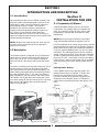
P
PECO
PTO
GRASS COLLECTION
SYSTEM
DESIGNED FOR:
MODEL 12031301, 12031302
GRAVELY 100 SERIES MOWERs
OPERATOR’S MANUAL
ASSEMBLY
MANUAL PART#: Q0322
OPERATION
$4.00
MAINTENANCE
REV: 0
PTO GRASS COLLECTION SYSTEM
TABLE OF CONTENTS
SECTION
PAGE SECTION
Safety - - - - - - - - - - - - - - - - - - - - - - - - - - - - - Safety Alert Symbols - - - - - - - - - - - - - - - - - - - - Warranty - - - - - - - - - - - - - - - - - - - - - - - - - - - I INTRODUCTION AND DESCRIPTION - - - - - - - - - - - - 1-1 Introduction - - - - - - - - - - - - - - - - - - - - - - - 1-2 Description - - - - - - - - - - - - - - - - - - - - - - - II INSTALLATION FOR USE - - - - - - - - - - - - - - - - - - - - 2-1 Preparation Of Mower - - - - - - - - - - - - - - - - 2-2 Attaching Muffler Guard - - - - - - - - - - - - - - - 2-3 Attaching Frame Mount Brackets - - - - - - - - - 2-4 Saftey Interlock Connection- - - - - - - - - - - - - 2-5 Belt Installation - - - - - - - - - - - - - - - - - - - - - 2-6 Cam Assembly Adjustment - - - - - - - - - - - - - 2-7 Attachment Of The Lower Frame To The Frame
Brackets - - - - - - - - - - - - - - - - - - - - - - - - - - - - 2-8 Attachment Of Upper Frame Assembly To The
Lower Frame - - - - - - - - - - - - - - - - - - - - - - - - - 2-9 Attachment Of The Top Assembly To The Upper
Frame Assembly - - - - - - - - - - - - - - - - - - - - - - 2-10 Attachment Of The Boot To The Mower Deck 2-11 Adjustment Of The Lengths Of Hoses - - - - - -
-
PAGE
2
2-12 Attachment Of The Upper Hose - - - - - - - - - 3
2-13 Attachment Of The Lower Hose To The Blower
4
Cone - - - - - - - - - - - - - - - - - - - - - - - - - - - - - - 5
2-14 Attachment Of The Lower Hose To The Boot - 5
2-15 Front Weight Assembly - - - - - - - - - - - - - - - 5
2-16 Installation/Removal Of Collection Bags - - - - 5
2-17 Final Checks - - - - - - - - - - - - - - - - - - - - - 5 III OPERATING INSTRUCTIONS - - - - - - - - - - - - - - - - - 6
3-1 General Safety - - - - - - - - - - - - - - - - - - - - - 6
3-2 Operation & Tips On Mowing - - - - - - - - - - - - 7
3-3 Disengagement Of The Blower - - - - - - - - - - 11
3-4 Unloading The Collection System - - - - - - - - - 11 IV MAINTENANCE - - - - - - - - - - - - - - - - - - - - - - - - - - 4-1 Maintenance Checklist - - - - - - - - - - - - - - - - 11
4-2 Lubrication- - - - - - - - - - - - - - - - - - - - - - - - V PARTS AND SERVICE - - - - - - - - - - - - - - - - - - - - - - 12
5-1 Parts And Service Information - - - - - - - - - - - Safety Decals - - - - - - - - - - - - - - - - - - - - - - - - 12
Torque Specifications - - - - - - - - - - - - - - - - - - - 12
Notes- - - - - - - - - - - - - - - - - - - - - - - - - - - - - - 13
- 13
-
13
13
13
14
15
15
15
15
15
15
15
15
16
16
16
17
18
19
Safety
1.
Read the operator’s manual carefully and familiarize yourself with the proper use of your attachment. Do not allow
anyone who is not acquainted with the Safety Instructions to use your attachment.
2. Know the controls and how to stop quickly. READ THE OPERATOR’S MANUAL!
3. Do not allow children to operate the vehicle. Do not allow adults to operate it without proper instruction.
4. Be especially watchful of children and pets darting into the area while operating.
5. Keep your eyes and mind on your unit while mowing or operating your attachment. Don’t let others distract you.
6. Do not attempt to operate your unit or mower when not in the driver’s seat.
7. Always stop unit when emptying the container.
8. Stop unit, shut off deck and attachment, set parking brake, shut off mower engine and remove spark plug wire
before removing clogs or removing or replacing hose, boot, blower cone, or performing any maintenance.
9. Mow up and down the face of slopes (not steeper than 10 degrees); never across the face of the slope.
10. It is recommended that the container be kept only half full when negotiating any slopes. Start mowing on slopes
when the container is empty.
11. Inspect your lawn and remove any foreign objects before mowing. Never deliberately run the mower across any
foreign object.
12. Wear ear protection if the noise level is offensive.
13. Wear eye protection to prevent debris from damaging your eyes.
14. Be alert for all other traffic when driving on public roads or highways.
15. Moisture content in most grasses can damage mower and grass collector components. Also, dry grass and leaves
left in the bags can be a fire hazard. Always make sure the bags are completely empty and the blower and hoses are
fully cleaned before storage.
2
SAFETY
WARNING!
NEVER operate the unit unless the discharge guard and either the deflector assembly or the
vacuum collector adapter are fastened securely in place.
WARNING! Do not work around the mower deck boot or the blower area until you are certain that the mower
blades and the blower impeller have stopped rotating.
WARNING! To avoid serious injury, perform maintenance on the vacuum collector; ONLY AFTER
STOPPING THE MOWER’S ENGINE AND WAITING FOR ALL MOVING PARTS TO COME TO A
COMPLETE STOP. Set the parking brake. Always remove the ignition key before beginning maintenance.
WARNING! For your own personal safety, ALWAYS mow UP and DOWN the face of slopes and NEVER
across the face. NEVER attempt to mow excessively steep slopes, and use caution when turning on any slope.
Safety Alert Symbol
!
This Safety Alert Symbol means: “ATTENTION! BECOME
ALERT! YOUR SAFETY IS INVOLVED!”
This symbol is used to call attention to safety precautions that
should be followed by the operator to avoid accidents. When
you see this symbol, carefully read the message that follows
and heed its advice. Failure to comply with safety precautions
could result in death or serious bodily injury.
Safety Signs
The signal words DANGER, WARNING, and CAUTION are used on the equipment safety signs. These words are
intended to alert the viewer to the existence and the degree of hazard seriousness.
! DANGER
This signal word indicates a potentially hazardous situation which, if not
avoided, will result in death or serious injury.
White letters on RED
! WARNING
Black letters on ORANGE
! CAUTION
Black letters on YELLOW
This signal word indicates a potentially hazardous situation which, if not
avoided, could result in death or serious injury.
It may also be used to alert against unsafe practices.
This signal word indicates a potentially hazardous situation exist which, if
not avoided, will result in minor or moderate injury.
It may also be used to alert against unsafe practices.
3
PECO LIMITED WARRANTY FOR NEW PRODUCTS
A. WHAT IS WARRANTED?
PECO extends the following warranties to the original purchaser of each new PECO consumer product subject
to the following limitations:
1. PRODUCT WARRANTY: Any part of any consumer product, which is defective in material or workmanship as
delivered to the purchaser will be repaired or replaced, as PECO elects, without charge for parts or labor, if the
defect appears within 12 months from the date of delivery of the product to the original purchaser. ALL
DEFECTIVE PARTS MUST BE RETURNED TO PECO FOR INSPECTION TO DETERMINE
VALIDITY OF WARRANTY CLAIMS. Freight and mailing will be borne by the customer.
2. PARTS REPLACED DURING WARRANTY: Any new PECO part which is furnished in performance of this
warranty and is defective in material or workmanship as delivered to the purchaser will be repaired or replaced,
as PECO elects, without charge if the defect appears within 90 days from the date of installation of such part or
before the expiration of the original warranty period, whichever is later.
B. SECURING WARRANTY ADJUSTMENTS.
Call PECO for Return Authorization. Damaged or broken parts, other than engines or batteries, must be
returned to PECO Inc., 100 Airport Road, Arden, NC 28704 before any warranty adjustment can be authorized.
At the time of requesting warranty adjustment, the purchaser must present evidence for date of delivery of the
product. The purchaser shall pay any charge for the product to and from Arden, NC.
C. ITEMS NOT COVERED BY PECO WARRANTY.
Engines and batteries attached to PECO products are covered under a separate warranty by the respective
manufacturer.
D. UNAPPROVED ALTERATION OR MODIFICATION.
All obligations of PECO Inc., under this warranty, shall be terminated if products are altered or modified in ways
not approved by PECO Inc..
E. ACCIDENTS AND NORMAL MAINTENANCE.
The warranty covers only defective material and workmanship. It does not cover depreciation or damage
caused by normal wear, accident, improper use or abuse of products. The cost of normal maintenance and
normal replacement of service items such as belts, cutting blades, hoses, etc., which are not defective shall be
paid for by the purchaser.
F. NO REPRESENTATIONS ADDITIONAL WARRANTIES, DISCLAIMER.
Neither PECO Inc. nor any company affiliated with it makes any warranties, representations or promises as to
the quality of performance of its products other than those set forth herein. Except as described above, PECO
Inc. makes no other warranties AND SPECIFICALLY DISCLAIMS ANY AND ALL IMPLIED
WARRANTIES OF FITNESS AND MERCHANTABILITY.
G. ANY MACHINE USED FOR RENTAL PURPOSES ARE GUARANTEED FOR 45 DAYS FROM DATE
OF ORIGINAL SALE ONLY.
H. REMEDIED EXCLUSIVE.
The only remedies the purchaser has in connection with the breach or performance of any warranty on PECO
Inc. consumer products are set forth above. In no event will PECO be liable for special incidental or
consequential damages.
1. NO SERVICE CENTER WARRANTY.
The selling Service Center makes no warranty on his own on any item warranted by PECO Inc. unless he
delivers to purchaser a separate written warranty certificate specifically warranting the item. The dealer has no
authority to make any representation or promise on behalf of PECO or to modify the terms of this warranty in
any way.
4
SECTION I
INTRODUCTION AND DESCRIPTION
1-1 Introduction
Section II
INSTALLATION FOR USE
We are pleased to have you as a PECO customer. Your
collection system has been designed to give you a low
maintenance, simple, and effective way to collect the
grass clippings from your mower. This manual is
provided to give you the necessary instructions to
properly mount and operate the collection system on
your mower. Please read this manual thoroughly.
Understand what each control is for and how to use it.
Observe all safety decal precautions on the machine and
noted throughout the manual.
2-1 Preparation Of Mower
Carefully dismantle shipping box from around the
components. Cut retaining straps and separate the
parts. The collection system will have various parts
located inside. Remove and sort all parts for easy
identification.
NOTE: Before each step of assembly it will help to
study the exploded drawings on pages 8,9 and 10.
NOTE: All references made to right, left, front, rear, top
or bottom are as viewed from the normal operator’s
position on the mower.
From the underside of the mower engine remove the bolt
and bushing from the electric clutch assembly. Replace
these parts with the engine pulley assembly P#(A0419),
7/16” lock washer P#(K0053) and 7/16”-20 x 4” HHCS
P#(K0359). The added pulley will power the collection
system. Note that the center of the hub that is extended
should be upward toward the engine (Figure 1). Torque
the bolt to 55 ft./lbs. Once pulley is secure, tie hydraulic
hoses (Figure 1) away from the pulley with (2) provided
zip ties to prevent pulley from making contact with the
hose.
1-2 Description
The collection system is designed for turf maintenance
where there is a need to collect the grass clippings as
the mower cuts the turf. It is also good for picking up
leaves and twigs in pre-season and post-season cleanup.
The blower, mounted on the right side of the unit, uses a
belt and gearbox system from the engine PTO shaft.
Drive train protection comes through belt slippage. The
blower draws grass clippings from the discharge area of
the cutter deck back to the 3 - 3.3 cubic foot collection
bags P#(G0002) at the rear portion of the mower frame.
The operator can engage the blower with a push of the
over-center linkage on the right side of the unit. Once the
bags are full with clippings, they can be released to
make for easy dumping.
Parking Brake Setting
For the added weight of the collection system, the
parking brake must be re-adjusted. To do this, first
Remove the rear wheels from the mower. Once
removed, reset the spring and the stop gap per the
dimensions in the diagram (Figure 2). Replace the
wheels when completed and torque each bolt to 51-72
ft./lbs.
Figure 2.
1.432”
Figure 1.
0.0” to 0.0625
Zip Tie Hose
Engine Pulley
7/16”-20 x 4” HHCS
5
.
Figure 4.
2-2 Attaching Muffler Guard
Locate the two exhaust diverters (P#J0251 w/ 1-1/4” ID,
P#J0250 w/ 1-3/8” ID) and clamp kit P#(X1046)
provided in the hardware bag. Fasten the correct size
exhaust deflector onto the mower’s exhaust and aim the
exhaust as shown in Figure 3. Next, fasten the exhaust
diverter by using the clamp kit.
Right
Left
Figure 3.
Mower’s Exhaust
Rear Of
Mower
3 Existing
Bolts Here
NOTE: Right and left views are as seen from drivers
perspective.
Figure 5.
Left Frame
Mount Brkt.
Exhaust Diverter
2-3 Attaching Frame Mount Brackets
To mount the frame brackets which support the bagger
unit, you must first remove the existing rear bumper.
This can be done by removing the three bolts and nuts
attaching the bumper to each side. Set the nuts and
bolts aside as they will be used to mount the frame
brackets. See Figure 4 for bracket orientation. Mount the
left frame mount bracket (Figure 5) by using three of the
existing bolts and three of the existing nuts. Tighten nuts
and bolts. The right frame mount bracket will mount
along with the PTO arm assembly (Figure 6). Align the
hole pattern on the side of the PTO arm assembly to the
hole pattern on the right frame mount bracket and
mower frame. Place each of the three remaining bolts
one at a time through the PTO Arm assembly, the right
frame bracket and through the existing holes of the
mower frame. Fasten the upper hole by using (1) 3/8”-16
x 1” HHCS P#(K1191) and (1) 3/8”-16 flange nut
P#(K1215). Tighten nuts and bolts.
Figure 6.
Right Frame
Mount Brkt.
Use 3 Existing Bolts To Mount
PTO Assy. Along With
Right Frame Mount Brkt.
To Tractor’s Frame.
6
Fasten Here With
3/8” x 1” HHCS
3/8” Flange Nut
PTO Arm Assembly
2-4 Safety Interlock Harness
Connection
Figure 9.
The safety interlock harness is located inside of the right
PTO arm assembly (Figure 7). To install the harness to
the mower, lift the hood of the mower for engine
compartment access. Route the harness as shown
towards the parking brake switch bracket on the mower
(Figure 8). Fasten the harness to the mower’s rear frame
by using (1) zip tie P#(J0245) to prevent the harness
from rubbing the mower’s tire. Next, remove the (2) bolts
(Figure 9) from the parking brake switch bracket for
access to the brown/yellow and red/violet wires. Remove
the brown/yellow wire from the parking brake switch and
connect to the brown/yellow wire of the harness.
Connect the red/violet wire to the parking brake switch,
where the brown/yellow wire was removed (Figure 10).
Replace the bolts removed from the parking brake
switch.
Figure 7.
Parking Brake
Switch Bolts
Figure 10.
Free End Of
Harness For
Routing
Harness
Connected
Here
Figure 8.
2-3 Attaching The Top Main Frame
Assembly
Place the top main frame assembly P#(00197800)
(Figure 9) onto the main frame legs and fasten each side
by using (1) 3/4”-10 x 1-1/2” HHCS P#(05959600), (1)
3/4”-10 nyloc nut P#(06540800), (1) ½”-13 x 1” HHCS
P#(05947100), and (1) pivot frame handle
P#(00194900). The handles are used to pivot the frame
to the rear for mower engine access. Be sure that the
handles are tight and the frame is in the upright position
before each use!
7
Figure 11.
Exploded View Of The
A0549 - Bagger Assembly
(2) K1144 - 5/16”-18 x 1”
CARRIAGE BOLT
(6) K1142 - 5/16”-18 x 3/4”
CARRIAGE BOLT
(4) K1010 - 1/4”-20 x 5/8”
CARRIAGE BOLT
(1) V0002 - PLASTIC TOP
(2) K1126 - 1/4”-20
FLANGE NUT
(1 LEFT, 1 RIGHT)
B0237 - PIVOT
BRACKET
(2) K0037 - 1/4” FLAT
WASHER
(1) V1054 - INLET
(1) C0048 LATCH MOUNT
BRACKET
(2) K1025 - 1/4”-20
x 1” CARRIAGE
BOLT
(1) B8002 - PLASTIC
SCREEN
(2) J4005 - FLEXIBLE
DRAW LATCH
(2) C0051 - LONG
SCREEN MOUNT
STRIP
(2) C0052 - SHORT
SCREEN MOUNT
STRIP
(2) C0047 - PIVOT
BRACE
(2) C0049 - SCREEN
BRACE
(1) V0005 - BAG RING SEAL
(8) K1178 - 5/16”-18
FLANGE NUT
(3) A0584 - BAG RING
ASSEMBLY
(6) J0274 - BAG RING END CAP
(2) K1180 - 5/16”-18
NYLOC NUT
(2) K0041 - 5/16”
FENDER WASHER
(2) K1153 - 5/16”-18
x 3/4” HHCS
(1) A0585 - UPPER FRAME
ASSEMBLY
8
Exploded Parts View
Figure 12.
Exploded View Of The Blower Assembly
2
1
3
4
5
2
6
7
9
12
11
13
8
10
24
21
33
Figure 13.
Exploded View Of The
A0506 - PTO Assembly
32
38
22
23
28
14
17
37
19
18
16
34
15
25
35
26
36
20
31
30
29
27
40
39
41
9
Parts View
46
55
54
42
47
56
44
50
43
57
53
48
58
52
45
51
49
Item
Part No.
Qty.
Description
1 - - - - E6009- - - - - - 1 - - - - Blower Cone 8”
2 - - - - K1159 - - - - - - 2 - - - - 5/16”-18 x 2” HHCS
3 - - - - A0914- - - - - - 1 - - - - 4 Blade Impeller
Assembly
4 - - - - K1193 - - - - - - 4 - - - - 3/8”-16 x 1-1/2” HHCS
5 - - - - E4004A - - - - - 1 - - - - Blower Housing
Assembly
6 - - - - A0306- - - - - - 1 - - - - PTO Shaft Assembly
7 - - - - K1215- - - - - - 4 - - - - 3/8”-16 Flange Nut
8 - - - - J0254 - - - - - - 1 - - - - 3/16” x 3/4” Key-way
9 - - - - M0228 - - - - - 1 - - - - Blower Pulley
10 - - - K1446- - - - - - 1 - - - - Washer
11 - - - K1190 - - - - - - 1 - - - - 3/8”-16 x 3/4” HHCS
12 - - - K1151 - - - - - - 1 - - - - 5/8” Black Handle Grip
13 - - - B0066- - - - - - 1 - - - - PTO Handle
14 - - - K0356- - - - - - 1 - - - - 3/8”-16 Set Screw
15 - - - A0422- - - - - - 1 - - - - Cam Bracket Assembly
16 - - - K0086- - - - - - 1 - - - - 1/8” x 2-3/8” Hair Pin
Clip
17 - - - K1178 - - - - - - 1 - - - - 5/16”-18 Flange Nut
18 - - - K1159 - - - - - - 1 - - - - 5/16”-18 x 2” HHCS
19 - - - WD0009 - - - - 1 - - - - Safety Interlock Harness
20 - - - A0510- - - - - - 1 - - - - PTO Arm Assembly
21 - - - K1197 - - - - - - 1 - - - - 3/8”-16 x 2-1/2” HHCS
22 - - - K1215- - - - - - 2 - - - - 3/8”-16 Flange Nut
23 - - - K1193 - - - - - - 2 - - - - 3/8”-16 x 1-1/2” HHCS
24 - - - B0076- - - - - - 1 - - - - Belt Guide Bracket
25 - - - A0429- - - - - - 1 - - - - Gear Box Assembly
26 - - - B0075- - - - - - 1 - - - - Pulley Guard
27 - - - K0353- - - - - - 2 - - - - 1/4”-20 x ½” HHSTS
28 - - - K1215- - - - - - 2 - - - - 3/8”-16 Flange Nut
29 - - - A0436- - - - - - 1 - - - - Belt Tension Bracket
Assembly
30 - - - K0047- - - - - - 1 - - - - 3/8” Flat Washer
Item
Part No.
Qty.
Description
31 - - - K0348- - - - - - 1 - - - - 3/8”-16 x 2” HHCS
32 - - - K0086- - - - - - 1 - - - - 1/8” x 2-3/8” Hair Pin
Clip
33 - - - B1755- - - - - - 1 - - - - Blower Pivot Rod
34 - - - K0130- - - - - - 1 - - - - 3/32” x 1-5/8” Hair Pin
Clip
35 - - - K0326- - - - - - 1 - - - - Belt Tension Rod 3/8”-16
36 - - - A0144- - - - - - 1 - - - - Blower Mount Brkt.
Assembly
37 - - - K0353- - - - - - 2 - - - - 1/4”-20 x ½” HHSTS
38 - - - B0121- - - - - - 1 - - - - Blower Belt Guard
39 - - - B0162- - - - - - 1 - - - - Skid Plate
40 - - - K1142 - - - - - - 4 - - - - 5/16”-18 x 3/4” CB
41 - - - K1178 - - - - - - 4 - - - - 5/16”-18 Flange Nut
42 - - - G0002 - - - - - 3 - - - - 3.3 Cu. Ft. Bag
43 - - - A0546- - - - - - 1 - - - - Lower Frame Assembly
44 - - - HB0204 - - - - - 1 - - - - Unit Hardware Bag
45 - - - B0174- - - - - - 1L,1R - Frame Mount Bracket
46 - - - - - - - - - - - - - 1 - - - - 6” x 20” Upper Hose
47 - - - - - - - - - - - - - 1 - - - - 8” x 31” Lower Hose
48 - - - P0145- - - - - - 1 - - - - Interlock Switch
49 - - - B0117 - - - - - - 1 - - - - Boot Hanger
50 - - - B0189- - - - - - 1 - - - - Boot Rod
51 - - - B0190- - - - - - 1 - - - - 44”, 48” & 52” Boot Plate
52 - - - HB0200 - - - - - 1 - - - - Boot Kit Hardware Bag
53 - - - B0188- - - - - - 1L,1R - Weight Bracket
54 - - - J6006 - - - - - - 2 - - - - Hose Clamp
55 - - - HB0186 - - - - - 1 - - - - Weight Kit Hardware
Bag
56 - - - B2220- - - - - - 1 - - - - Weight Bar
57 - - - B0204- - - - - - 1 - - - - 60” Boot Plate
58 - - - E1113 - - - - - - 1 - - - - 44”, 48” & 52” Boot
E1034- - - - - - 1 - - - - 60” Boot
- - - - - M0243 - - - - - 1 - - - - A49K Kevlar Cord Belt
- - - - - M0237 - - - - - 1 - - - - A33K Kevlar Cord Belt
10
2-5 Belt Installation
Loosen the (2) bolts that secure the gear box assembly
P#(A0429) to the PTO mount plate (Figure 14). Loosen
the adjustment bolt P#(K0348) until the gear box
assembly is at its far left adjustment (the gear box is
moved towards the mower’s engine pulley). Connect the
kevlar cord belt from the engine pulley to the lower gear
box pulley (Figure 15).
P#(K0326) and pull the “L” end of the rod out of its hole
in the cam assembly. The tension rod may then be
screwed out to tighten the belt or screwed in to loosen
the belt. Replace the “L” end into the top hole in the cam
and replace the hair pin clip. Adjust the cam stop bolt
P#(K1159) to allow the cam to rotate slightly over center
when the blower is disengaged (Figure 16).
Cam Assy.
Figure 16.
To tension the drive belt, turn the adjustment bolt
clockwise until there is 1” of deflection, with 10-11 lbs. of
pressure between the engine pulley and the gear box
pulley.
Once the correct tension of the belt is achieved, tighten
the (2) bolts that secure the gear box assembly.
Adjustment Bolt
Figure 14.
Cam Stop
Bolt
Tension Rod
2-7 Attachment Of Lower Frame To
The Frame Brackets.
PTO Mount Plate
Figure 15.
Gear Box Assy.
Using (2) ½”-13 u-bolts P#(K0288) and (2) ½”-13 nyloc
nuts P#(K1247) , attach lower frame to the left and right
frame mount brackets as shown in Figure 17. Make sure
the lower horizontal tube is centered in regards to the
lower frame mount brackets. The lower frame stiffening
bracket is to be positioned towards the engine mower’s
engine.
Figure 17.
Left Frame
Mount Bracket
Lower Frame
Right Frame
Mount Bracket
Engine Pulley
2-6 Cam Assembly Adjustment
The cam assembly P#(A0422), which controls the
blower belt tension, comes from the factory pre-adjusted.
If the belt is too tight or becomes too loose, remove the
hair pin clip P#(K0099) from the belt tension rod
Lower Frame Centered
In Regards To U-Bolts
Mounted To Frame Brackets
11
2-8 Attachment Of Upper Frame
Assembly To The Lower Frame
2-10 Attachment Of The Boot To The
Mower Deck
NOTE: During this step, it is suggested that two
people install the top frame to the lower frame.
Using two people to raise the top frame, lift the top frame
above the lower frame making sure the bag frames are
located away from the engine as shown in Figure 18.
Slide the top frame vertical tube into the lower Frame
vertical tube aligning the holes. Insert (1) ½” x 2-1/2”
clevis pin P#(K0133) through the holes and fasten with
(1) 5/32” x 2-5/8” hair pin clip P#(K0088).
Mounting The Boot Hanger
Remove the mower’s deflector shield mount (Figure 20).
Position the notch towards the front of unit and place the
boot hanger P#(B0117) in-between the deflector shield
mount and the mower deck. Fasten by using (3) 3/8”-16
x 1-1/4” HHCS P#(K1192) and the existing 3/8” nuts. The
boot hanger will allow you to switch from collection to
discharge in seconds.
Figure 18.
60” Boot Plate Mounting Instructions
To mount the boot plate P#(B0204) to the boot
P#(E1034) use (3) 3/8”-16 x 1” carriage bolts P#(K1182)
and (3) 3/8”-16 flange nuts P#(K1215).
Top Frame
44”, 48” & 52” Boot Plate Mounting Instructions
To mount the boot plate P#(B0190) to the boot
P#(E1113) use (2) 3/8”-16 x 3/4” carriage bolts
P#(K1181) and (2) 3/8”-16 flange nuts P#(K1215).
Note: When bolting the boot and boot plate together,
the head of the bolt is placed from the inside of the boot.
This will prevent grass from collecting on the bolts.
Lower Frame
For All Deck Sizes
Remove the bolts from that hold the deflector shield in
place so that the boot rod can fasten the boot and boot
plate to the mower deck. Align the holes in the boot plate
to the holes in the deflector shield mount and slide the
boot rod, P#(B2540) for the 60” Deck and P#(B0189) for
the 52” deck, through and fasten by using (1) hair pin
clip P#(K0099).
½” x 2-1/2” Clevis Pin
5/32” x 2-5/8”
Hair Pin Clip
2-9 Attachment of Top Assembly To
The Upper Frame Assembly
Note: The Mower’s Deflector Shield Has Been
Removed In The Following Photo For Clarity. Always
have the deflector shield mounted when mowing.
Align the pivot brackets of the top assembly P#(A0551)
to the pivot point on either side of the upper frame
assembly. Place (1) P#(K0041) fender washer between
each pivot point (Figure 19) and fasten each side by
using (1) P#(K1153) 5/16”-18 x 3/4” HHCS and (1)
P#(K1180) 5/16”-18 nyloc nut. When fastening leave nut
slightly loose so that the top can pivot freely.
Figure 19.
Figure 20.
Mower Deck
Deflector Shield Mount
Boot Hanger
Notch
Top Assembly Here
Fasten Here With
5/16” x 3/4” HHCS
5/16” Nyloc Nut
Fender Washer
Boot Plate
12
Boot Rod
Boot
2-11 Adjustment Of The Lengths Of
Hoses
2-13 Attachment Of The Lower Hose
To The Blower Cone
The hoses in steps 2-12 and 2-13 must be cut to fit your
machine. Follow steps 2-12 and 2-13. Do not cut the
hoses until you have tried to fit them on your machine.
Remember that the hoses have to be long enough to
allow for enough clamping surface between the inlet,
blower assembly, and the deck boot.
Fasten the blower cone P#(E6009) to the blower
housing by using (2) 5/16”-18 x 2-1/2” HHCS P#(K0125)
and (2) 5/16”-18 jam nuts P#(K0120). Slide a 7”-8” hose
clamp P#(J6006) over both ends of the lower hose. Then
proceed to slide the lower hose onto the blower cone.
Tighten the hose clamp. The assembly should look like
Figure 21.
2-12 Attachment Of The Upper Hose
2-14 Attachment Of The Lower Hose
To The Boot
Fasten the inlet to the plastic top by sliding the inlet from
the inside of the top to the outside and lock into place.
Slide a 5”-6” upper hose clamp P#(J6011) onto both
ends of the 6” upper hose (Figure 21). Then slide one
end of the 6” hose onto the inlet. Make sure there is
about a two-inch overlap between the hose end and the
container inlet. Proceed to slide the opposite end of the
6” hose onto the outlet of the blower assembly. See
Figure 21 for details. Make sure both ends of the hose
are clearly attached to the inlet and the blower assembly
inlet. Tighten the hose clamps.
Figure 21.
Inlet
5”-6”
Clamp
6” Upper
Hose
8” Lower
Hose
Take the unattached end of the lower hose and slide it
over the circular end of the boot. Use the lower hose
clamp to secure the hose to the boot (Figure 21). Tip:
Before securing clamp rotate hose counter-clockwise
(away from yourself) approximately 1” to add in retaining
boot to mower deck.
2-15 Front Weight Assembly
Attach each weight bracket P#(B0188) to the mower’s
front casters by using (1) 3/4”-10 x 1-1/2” HHCS
P#(K0364) and (1) 3/4”-10 nyloc nut P#(K1433) (Figure
22). When installing the 100 lb. weight you should have
another person help position the weight onto a floor jack.
Using the floor jack will make installing the weight much
easier. Lift the weight up to the top of the weight
brackets. Fasten the weight to the weight brackets by
using (1) ½”-13 X 4-1/4” U-Bolt P#(K0331) and (2) ½”-13
flange nuts P#(K1246) per bracket. Once the weight is
secure tighten all nuts. Be sure Weight is centered in
reference to the U-Bolts.
Figure 22.
3/4”-10 X 1-1/2” HHCS
3/4”-10 Nylock Nut
Blower
Boot
Blower Cone
7”-8”
Clamp
Right
Weight
Bracket
Left
Weight
Bracket
Weight
13
2-16 Installation/Removal Of
Collection Bags
Figure 24.
Plastic Top
To install the bag onto the bag ring, first make sure the
bag ring end caps are fastened to the bag ring. Place the
seam openings of the bag onto the bag ring openings
and turn the bag until the slot bracket in the bag ring is
protruding from the opening in the bag (Figure 23). Do
this for each of three bags.
Install the completed assemblies onto the support frame
and close the plastic top. Fasten both draw latches to
hold the plastic top closed (Figure 24).
To empty the bag, remove the bag and bag ring by lifting
and sliding rearward. Grasp the loop on the bottom of
the bag, turn it upside down and empty the collected
debris (Figure 25). Repeat for the other bags. Reinstall
all bags, line with plastic bags if desired, close the plastic
top and reattach the draw latches.
Draw Latches
Figure 25.
Plastic lawn and leaf bags, 33 gallon size, may be used
inside the cloth bags. Be sure to leave enough plastic
bag hanging over the frame so the plastic bags can be
twist tied before emptying (Figure 26).
Figure 23.
Bag Ring
Slot
Bracket
Grasp Bag
Here
Figure 26.
Plastic Bag
Bag Ring
End Caps
Cloth Bag
Cloth Bag
14
* Mow twice, at different height settings, (high, then low),
if grass is extra tall.
* Remember that horsepower requirements will vary with
the mowing conditions such as type and height of turf
grass, moisture content, amount of leaves, whether the
terrain is flat or hilly, etc.
2-17 Final Checks
To check the operation of the safety interlock harness
perform the following:
A. Start mower
B. While seated in the operator’s seat, rotate the
engagement handle of the collection system away
from the mower.
C. With the blower engaged, stand up from the
operator’s seat. This action will shut off the mower
which verifies proper installation of the harness.
D. Check the mower’s safety interlock, see mower’s
manual for more detail.
NOTE: If the mower does not shut off, turn off mower
and refer to page 7 to verify proper installation of the
harness. If problem persists contact your local dealer.
3-3 Disengagement Of The Blower
A. To disengage the blower, rotate the engagement
handle towards the mower.
WARNING: The blower will continue to spin. DO NOT
TOUCH the blower, pulleys, or the belt until the tractor is
turned off. DO NOT adjust the belt tension until the
mower is turned off. Refer to section 2-6 of the manual.
3-4 Unloading The Collection System
SECTION III
OPERATING INSTRUCTIONS
NOTE: To determine when the collection bags are full,
follow the following steps:
3-1 General Safety
A. Stop the forward movement of the mower.
B. Disengage the mower deck.
C. Disengage the blower.
D. Engage the parking brake.
E. Once the parking brake has been engaged, then and
only then, walk behind the mower and check the
collection bags by lifting the plastic hood. Load in
bags should not exceed the height of the installed
bag.
F. To release bags from frame, lift bag ring from tab on
bagger frame, slide bag out and turn bags over to
deposit clippings.
G. Follow steps on page 14 to re-attach bags back to the
bagger.
NOTE: Do not allow collection bags to become overfilled as potential damage may occur to your
equipment. Also, be sure to clean the hood screen as
needed.
Only qualified people familiar with this operator’s manual
and the mower’s operator’s manual should operate this
machine.
3-2 Operation And Tips On Mowing
A. Perform BEFORE EACH USE the maintenance list in
paragraph 4-1.
B. Start mower.
C. With the mower at high idle speed, engage the mower
deck.
D. While seated in the operator’s seat, rotate the
engagement handle of the collection system away
from the mower. Continue to rotate the handle until it
stops in an over center position. With the blower
engaged, you can proceed to operate the control
levers of the mower.
NOTE: If the collection system does not appear to be
collecting the grass clippings, disengage the deck
and blower, then, engage the parking brake and turn the
mower off. Proceed to section 3-3, and review the
section 2-6, in this manual.
SECTION IV
MAINTENANCE
To obtain the maximum effectiveness from your
collection system the tips listed below should be
followed:
4-1 Maintenance Checklist
Before each use:
1. Check blades and spindles to be sure that no foreign
objects, such as wire or steel strapping bands, are
wrapped around them.
2. Inspect blades for wear. Replace if necessary. If it is
necessary to sharpen the blades, remove the blades
from the spindles before sharpening. DO NOT
sharpen blades while still attached to the mower.
* Watch your speed- Normal conditions will allow a
speed of up to approximately 5 mph, but thick, heavy
damp conditions will require reduced ground speed.
* Mow with sharp blades- A sharp blade cuts cleaner.
* Wet grass and leaves will decrease effectiveness and
will increase horsepower requirements.
* Mow at higher cutting heights- Remove and mulch no
more than 2” of grass length with each mowing.
(Experts recommend not cutting off more than 1/3 of
the grass blade length at any given time.)
15
3. Make sure all shields are in place and in good
condition. Repair or replace any missing or damaged
shields.
4. Perform lubrication per paragraph 4-2.
5. Listen for abnormal sounds, which might indicate
loose parts, damaged bearings, or other damage.
Correct any deficiency before continuing operation.
6. With the engine off, engage the blower assembly.
Check the belt tension and inspect the pulley belt for
cracks or tears.
7. Check for wear or deterioration of the upper or lower
hoses. If there are any portions of the hose that have
been torn or worn through, replace with genuine
PECO parts.
SECTION V
PARTS AND SERVICE
5-1 Parts And Service Information
PECO collection system owners should record the name
and telephone number of their Service Center. Your
Service Center will be happy to supply replacement
parts, accessories, and do any service or repairs to your
collection system. If for any reason your Service Center
is unable to service your collection system or supply
replacement parts, contact PECO and include the
following information on the chart below.
After Each Use:
1. Clean all debris from machine especially from the
container, underneath the belt shields, and off of
safety decals. Replace any missing or illegible decals.
2. Inspect the unit for worn or damaged components.
Repair or replace before the next use. Any
replacement component installed during repair shall
include the component’s current safety decal specified
by the manufacturers to be affixed to the component.
3. Check belt for proper tension.
THE SERIAL NUMBER PLATE IS LOCATED ON THE
LOWER FRAME ASSEMBLY P#(A0546)
PECO
OUTDOOR POWER EQUIPMENT
Model Number
4-2 Lubrication
Serial Number
Arden, North Carolina 28704
NOTE: Use only white lithium based grease for
lubrication of the shaft on the blower assembly.
WRITE THE MODEL AND SERIAL NUMBER IN
THE BOX ABOVE FOR FUTURE REFERENCE.
1. On initial use: Grease the fitting on the blower shaft.
2. Every 25 hours of use: Re-grease the grease fitting.
3. Every 200 hours of use: Check oil levels in gear box.
Oil in gear box should cover the gears. If not, fill using
an EP90 weight oil. 6oz. will fill the gear box from
empty.
Unit Model Number: _____________________________
Unit Engine Size:
_____________________________
Unit Serial Number: _____________________________
Date of purchase: _____/_____/_________
Dealer/Distributor Name:
________________________________________
Dealer’s/Distributor’s: _______________________ State: __________ Zip: ___________
Phone Number: ____________________________
Address: PECO Inc.
P.O. Box 1197
Arden, NC 28704
Phone #: (828) 684-1234 or Toll Free: (800) 438-5823
Email: [email protected]
16
SAFETY DECALS
To promote safe operation, PECO supplies safety decals on all products manufactured. Damage can occur to
safety decals either through shipment, use or reconditioning. Contact your local Service Center for replacement decals.
Part #:R1051
Part #: R1054
Part #: R1057
Part #: R1065
Part #: R1050
Part #: R4037
Part #:R1083
Part #: R1052
Part #: R1090
17
18
NOTES
19
Turn any PECO Lawn Vac into a total
lawn grooming tool with the PECO
Wand Kit!
With your PECO Wand Attachment you will
double the ability of your PECO Lawn Vac.
Using the same powerful vacuum/blower that
makes your Lawn Vac work so well, you will be
able to get to all those hard-to-reach places
where you needed a rake or broom before.
Contact PECO Today!
P
PECO
P.O. BOX 1197
ARDEN, NORTH CAROLINA 28704
(800) 438-5823 OR (828) 684-1234 FAX: (828) 684-0858
EMAIL: [email protected]
WEBSITE: www.lawnvac.com