1
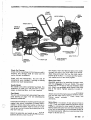
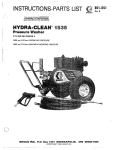
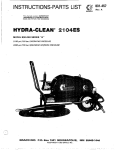
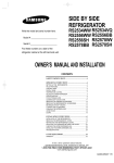
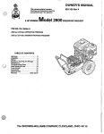
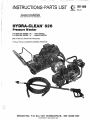
This manual contains IMPORTANT
WARNINGS and INSTRUCTIONS
READ AND RETAlN FOR REFERENCE
Q
P/N 800-093SERIES "A"
P/N 800-094SERIES "A"
- CART MODEL
- HANDLE MODEL
800 psi (55 bar) OPERATING PRESSURE
1 100 psi (76bar) M A X I M U M WORKING PRESSURE
UNJECTUON HAZARD
Fluids under high pressure from spray
or leaks can
penetrate the skin and cause extremely serious
injury. including the need for amputation.
NEVER point thespray gun at anyone
or any partof
Do not use chemicals or agents which are not
compatible with Viton andPVC or neoprene cover of
hose.
Do not leave apressurized unit unattended. Shut off
the unit and release pressure before
leaving.
the body.
FUWE
NEVER put hand or fingers over t h e spray tip.
Do not spray flammable liquids.Do not operate the
NEVER try tostop or deflect leaks with your hand or
body.
'
unit where combustible fumes or dust may be
present.
'
GENERAL
MEDICAL TREATMENT
If any fluid appears to penetrate your skin, get
E M E R G E N C Y MEDUCAL CARE AB ONCE.
DO NOT TREAT AS A SIMPLE CUR.
Tell the doctorexactly what fluid was injected.
For
treatment instructions have your doctor call the
NATUONAL POISON CENTER NETWORK
(rgt2)681-5569
AVOID COMPC3NENT RUPTURE
Even after you shut off the electric
motor, there is
high pressure in the pump, hose and gun
until you
release it by triggering the gun.So before removing
the spray tip
or servicing theunit, always shutoff the
unit and trigger thegun t o release pressure.
Observe detergent manufacturer's safety
precautions. Avoid getting detergent or other liquids
in your eyes. Follow the directions on the container
regarding contact with eyes. nose, and skin,
breathing fumes, etc. Always wear full goggles t o
protect your eyes from spray
the as well as anydebris
dislodged by thespray. If necessary. wear gloves or
other protective clothing. If antidotes
or treatment
are recommended, be prepared to use them.
D O N T spray toxic chemicals suchas insecticide or
weed killer.
This unit is supplied with an 8-foot power
cord made
up of three AWGNo. 14 wires. The green wire of the
electric cord is connected to theunit chassis and
motor frame. The othertwo wiresare connected to
the starter switch.
Be sure that all accessory items and system
developed.
components will withstand the pressure
NEVER exceed the pressure rating of any componentThe starter switch has a built-in ground fault
in system. NEVER alter or modify equipment-your
interrupter that will shut off the power to the
unit
personal safety. as well as the function of the
.
whenever an improper ground condition
exists.
equipment, is at stake.
Always check to be sure the switcho f is
fandthat the
Before each use, check hose for weak, worn or
hoses and electric cord areclear of moving parts
damaged conditions caused
by traffic, sharpcorners,
before pluggingin the powercord,
pinching or kinking. Tighten all fluid connections
securely before each use. Replace any damaged
hose.
,
IMPORTANT
United States Government safety standards have adopted
been under the Occupational
Safety and Health Act.
These standards-particularly the GeneralStandards, Part 1910,andthe ConstructionStandards, Part1926Should be consultedin connection with your useof airless spray equipment,
2
.
801-888
.
..
~.
. .
.
.
.. . . . ... .. .
.
..
~.
.. . .,
. .
.
.. .
. ..
~.
CART
MOTOR CONTROL
j
POWER COR0
HANDLE
MODEL
ADJUSTABLE NOZZLE
CONTROL RING
3/4" GARDEN
HOSE THREAD
4
PRESSURE
AOJUSTMENT
4
SPRAYTIP H6")
HIGH PRESSURE
HOSE I30 FT.)
KNOB
Check For Damage
Check unit for any
damage that may have occurredin
shipping. Any damage should be noted and the
carrier notified immediately.
Check unit' and accessories to be sure that all
components were included. If anything is. missing
contact your localrepresentative.
Handle Model
The handle unit comes completely assembled. The
installation of hose, gun and connection to water
supply. as described later, Is all that is required.
Cart Model
The c a n unit comes partiallyassembled. Refer to the
parts drawing on page 7 for aid when following
assembly procedures.
,.. .. . . .;,...
'5.
...>,:
',
.
Install axle and wheelsby inserting axle through
axle
'support tube which is attached chassis.
to
Place a
washer, a wheel, and another washer
on the axle on.
both sides of the chassis. Insert a cotter pin into the
hole ateach endpf theaxle. Bend cotter pinsover so
they won't fallout.
Attach leg assembly and handle
by putting the leg
assembly directly under the unit towards theof front
the chassis. Insert the flattened
tabs on the handle
through the slots in the front edge of the chassis.
Align holes and insert the four
hex head machine
Screws (3/8-16NC x 1-1 /4 inch) with flat washer,
lock washer and nut and firmly tighten,
Spray Gun/Hose
Assemble spray gun by attaching the spray wand
with its safety grip to the gun handle.
The wand
comes with PTFE tapeon the pipe threads at each
end. Attach the adjustablespray nozzle to the other
end of the wand. Tighten securely to avoid any
leaking.
Attach one end
of the high pressure
hose to thespray
gun and the other end to the high pressure outlet.
Tighten swivel connections firmly using two
wrenches..
Spray Hose
A 30 foot (9.1 m ) section of high pressure hose is
supplied with this
model. Additional sections may
be
ordered to increase the hose length.
Be aware that
adding additionalspray hose will lower the pressure
of the unit at thespray gun anddecrease suction of
the chemical injector. Maximum recommended hose
length is 90 feet (27 m).
801-888
3
NOPE:
Connect To Water Supply
-CAUTION
plumbing codes regarding cross-connection to
water supply. Optional backflowpreventorP/N
801-1 33 is available to prevent the back-up
of
~~
For a direct supply system, your wafer
source at the unit must have a flow
rate of at least 4 GPM (15 liter/min).
Electrical Service
an approved
Before plugging the sprayer into
electrical receptacle be sure that the electrical
service is singlephase, 115 V, 60 Hz AC. 15 Amp,
in the OFF position,
With the motor control switch
plug the power cord intoa grounded outlet. If an
extension cordis used, be sure thatit has a ground
and that the wiregage i s at least No. 14 gage wire.
The cord should not
be over 100feet (30m) long. See
the operation section for further characteristics on
the motor control switch,
Do not exceed 1 G O O F (70'C) water temperature to
pump ina direct supplysystem.
Connect a hose with at least
3/4 inch (19 mm) I.D.
from your city water supply to the units
3/d inch
garden hose threaded inlet.The supply hose should
not be longer than 5 0 feet (15 m) long.
OPERATION
startup
Before starting,be sure to read the safety warnings
and startup instructions.
.With the control ring turned completely counterall water pressurewill
clockwise (viewed from front)
be directed through the spray tip orifice. In this
position the normal spray patternof 15" will take
place.
Turn .on the water supply
Trigger the gunto release anyback pressure
To change the spray pattern simply turn
the control
ring clockwise. This will cause
a drop in pressure
which will activate the downstream chemical
DO NOT wire or tie the gun trigger into open
the
or triggered position.
~~~~~~~
CAUTION
injector.
When full strength sprayingis desired, turn control
ring counterclockwiseto closed position.
-
~A~~~~~~
Never run the cleaning unit dry.
Costly damage
to the pump will result. Always
be sure water
supply is completelyturned on before operating.
DO NOT attempt to adjustnozzle when spray
gun is in use. Be sure that the safety latch on
gun is in the ON position before adjusting.
Inspect all connections for any leaks. Tighten if
necessary.
Pressure Adjustment
The pressure washer has been factory adjusted to
Motor,Control Switch
deliver 800 k25 PSI (measured at the pump outlet).
As indicated earlierin this manual the motor control This is the maximum pressure that this unit is
switch hasa built in ground fault interrupter circuit. designed for. However, this pressure
can be
Due to this special protection feature
of the switch, if
decreased by turning the control knob locatedthe.
on
the switch "ON" button is pushed in while the
unit is
unloader valve on 'the outlet side of the pump.
unplugged, the unit will go into the "ON" mode.
Turning the control knob in a clockwise direction
When plugged in, unit will immediately start.The
(viewed fromabove the unit) will gradually
decrease
switch cannot be turned off untilit isenergized. Once
the output pressure and flow.
power is applied to unit,switch can be turned off.
Chemical Injector
A downstream chemical injector is provided with the
NOTE: Always use the motor control switch
when starting and stopping unit. Avoid
pressure washer. Insert chemical filter that is
inadvertently pushing "ON" button
to chemical injector into
attached with clear tubing
when unit is unplugged.
the top of the desired chemical container.
Cleaning
.
Start unit by lifting the cover on the motor control
switch and pushing the "START" button.
This button
is also marked"RESET". Pull trigger on gunand unit
should start spraying.
The chemicalsused must be compatible withsystem
components. The standard spray hose is made of
'Buna-N rubber, and the chemical injector brass.
is
WI&3N8M'G
Observe chemical manufacturer's safety precautions regarding use of goggles, protective
clothing or respirators.
The spray pattern can be changed by turning the
control ring on the adjustable
spray nozzle.
L
~
~-
Turn control ring on adjustable
nozzle clockwise to
cause a drop in pressure.
Start pressure washer unit and trigger spray gun. The.
injector may draw momentarily as system is filling but
pressure.To
normally will stop as system builds up to full
actuate injector, turn chemical adjustment knob out.
counterclockwise. until chemical begins to be drawn
from thecontainer. After the chemicalreaches injector,
flow rate may be adjusted by turning the adjustment
knob. At two full turns fromthe closed position of the
chemical adjustment knob, maximum chemical flow is
obtained. Do not exceed two turns.
nozzle
Check the distanceyou will need to hold spray
from surface by test spraying on
a scrap of similar
material. For soft surfaces, such as wood, hold nozzle
it
about 3 feet ( 1 m)from surface and gradually bring
closer, check. to see if the high pressurespray is
damaging the surface.
Mist-wet surface with cleaning solution. it
Let
soak
briefly, thenuse spray rinse to “chisel” off dirt.
Keep
nozzle at an angle tosurface, and at distance you
determined to be best for surface. If some dirt
remains, repeat procedure, letting. it soak a little
off better with a
longer. Stubborndirt can be cleaned
stronger, heated cleaning solution.
Protect surfaces that mightbe damaged by cleaning
solution or high pressure spray, and rinse solution
before it dries.
Shutdown And CareOf Unit
When unit is not
in use, turn off watersupply.
When shutting down for day
theorweekend, shut off
unit, shut off water supply
valve, and trigger gun to
unit with a damp rag.
release pressure. Wipe off the
Check the filterscreen in the water inlet connection
as often as necessary, a t least daily. Do not operate
the unitwith the inlet and filter screen removed.
PUMP MUST NOT BE RUN DRY and mustbe drained
of water prior to exposure to freezing temperatures.’
Use and store the unit where
it will not be subjected
to freezing temperatures. If water
does freeze in the
unit, thaw before trying to start.
A 50% anti-freeze
solution may be pumped prior to cold weather
storage.
to the unit to
Use only spray tips that are matched
avoid excessive cycling and wear of the unloader
valve.
CAUTION
pour hot water ona frozen pump. A sudden
temperature change may crack the ceramic
Do not pump caustic materials.
Before extended storage, flush the pump with light
oil.
Avoid dragging hoseoveranabrasivesurfacesuchas
cement. This causes excessive wear and shorter
hose life.
Clean the intake line strainer daily.
Lubrication and Care
Fill pump crankcase to
dot on oil gauge window with
1 0 . 2 0 ~(.0.3
.
liters) of crankcaseoil (part no. 801-144)
or equivalent SAE 20/30 weight hydraulic oil with
anti-wear and rust inhibitor additives.
Change initial
Change oil every 3
fill after 50 hour running period.
months or at 500 hour intervals.
This model runs with
very little noise due to size
the
Winter Maintenance
ofthemotorandpump.Besurethattheunitisturned
off when notin use. If unit is left running, when not 1. Turn off and disconnect water supply and
discharge lines.
actually using spray gun, the buildof up
temperature
in the, by-pass loop of the pump couldexceed the
manufacturer’s specifications of 1 6 B F (71OC)
2. Pump a 50% antifreeze solution through the
machine making sure all water has been
maximum. Thiswill cause shortened pump life.
displaced.
CAUTION
spraying, for longer pump life.The pump will
overheat if left running for over 10 minutes
3. When machine is needed, connect the water
supply and circulate the antifreeze from the
reuse. When the water
machine to containers for
flowing from the outlet becomes
clear, reconnect
discharge lines.
801-888
5
SERVICE
Troubleshooting
PROBLEM
CAUSE
SOLUTION
Low.Pressure
Worn nozzle.
Coupling slippage.
Air leak in inlet plumbing.
Relief valve stuck, partially
plugged or improperly
adjusted; valve seat worn.
Inlet suction strainer clogged
or improper size. :
Worn packing. Abrasives in
pumped fluid or severe cavita:
tion. Inadequate water supply.
Fouled or dirty inlet or discharge valves.
Worn inlet or discharge valves.
Leaky discharge hose.
Pressure adjustment set down.
Replace with nozzle of proper size.
Tighten or replace.
Disassemble, reseal, and reassemble.
Clean, and adjust reliefvalve; check for
worn and dirtyvalve seats. Kit available.
Restricted inlet or air
entering the inlet plumbing.
Inlet restrictions and/or air
leaks. Stuck inlet or discharge
valve.
Leaking high pressure seals.
'roper size inlet plumbing: check for air
:ight seal.
:lean out foreign material, replace worn
Ialves.
iNater leakagefrom under
:he manifold.
Worn packing.
nstall newpacking.
iNater in pump crankcase.
May be caused by humid air
condensing into waterinside
the crankcase.
:hange oil at 3 month or 500 hour intervals
)sing Crankcase Oil (other approved oil every
nonth or 200 hours) P.N. 801-144.
Zrequent or premature
'ailure of the packing.
Scored plungers.
leplace plungers
Over pressure to inlet manifold.
Damaged orworn plungers.
4brasive material in the fluid
3eing pumped.
Excessive pressure and/or
:emperatwe of fluid being
Jumped.
3ver pressure of pump.
7unning pump dry.
leduce inlet pressure.
leplace plungers.
nstall proper filtration on pump inlet
Ilumbing.
:heck pressures and fluid inlet
temperature;
le sure they are within specified range.
rump runs extremely
rough, pressure low.
jtrong surging at the inlet
Ind low pressure on the
lischarge side.
:oreign particles in the inlet or
lischarge valve, or worn inlet
and/or discharge valves.
h i t will notstart.
Jnit not plugged in.
j.F.1.C. activated.
ilectric motor overheated.
ilectric service off.
:hemica1 injection system
oesn't work.
pray gun doesn't work
r leaks.
6
801-888
:hemica1 injector clogged.
Clean. Use adequate size. Check more
frequently.
Install proper filter. Check flow available to
pump.
Clean inlet and discharge valve assemblies.
Replace worn valves, valve seats and/or
discharge hose.
rurn adjustment knob counter:lockwise to increase pressure.
7eplace seals.
I
leduce pressure.
Do not run pump without
water.
Check for smooth lap surfaces on inlet and
discharge valve seats. Discharge valve seats
and inlet valve seats may be lapped on a very
fine oilstone.,
Check power cord.
Check for proper grounding.
Push switch ON (RESET) button.
Let motor cool and push reset button
on rear of motor.
,
Check fuse/circuit breaker panel.
\djustable nozzle completely
losed.
.ow chemical level.
Disassemble chemical valve and clean.
Check and clean chemical hose and filter.
Turn control ringon nozzle clockwise
to cause drop in pressure.
Check level of chemical.
iun cartridge needs replace-
Replace cartridge (see gunparts drawing).
BARBS DRAWING
Pressure Washer A
33.
WIRING DIAGRAM
:
.
,
... .
..
.
.
801-888
7
PARTS LIST
Pressure Washer Assembly, 800-093.800-094
REF. PART
NO. NO.
800-093
800-094
i
2
3
4
5
6
7
8
9
10
11
12
13
14
15
16
17
18
19
20
21
22
23
24
25
26
27
28
29
8
800.154
800.157
801-859
801-931
801-929
801-966
801-930
801-893
801.884
801.884
801-226
801-304
801-221
801-894
801-605
801-606
801-875
801.876
801-882
*EO1 -883,
801-967
801.677
801-683
801-129
801-008
801,388
801-417
801.524
801-501
801-888
DESCRIPTION
QTY
PRESSURE WASHER ASSY..
Cart Model (Includes items
1-52, 61, 62
PRESSURE WASHER ASSY.,
Handle Model (Includes
items 1-35, 53-60
PUMP/MOTOR ASSY., see
parts drawing, pg.9
1
GUN ASSY., see parts
1
drawing, pg. 13
SWITCH MOUNTING BRACKET
1
1
CORD GRIP
CONNECTION, Conduit, 90°
2
CORD, with 15 Amp Plua
1
CONDUIT,. 3/8
18"
BOX, Switch
1
COVER, Switch
1
SWITCH/G.F.I.
1
WIRE NUT, Orange
7
2
CRIMP CONNECTOR, Blue
CRIMP CONNECTOR, YELLOW
1
SCREW, Self Tapping, #lo
1
BOLT, 10-24x 3/4
2
FLATWASHER. 3/16
4
2
LOCKWASHER, #10
NUT, 10-24
2
COUPUNG.3/8NPTMx1/4NPSF
1
TIP. 15065
1
HOSE. Hiah Pressure.30 ft.
1
TUBING. themica( 5/16 I.D.
8'
1
FILTER. Chemical
L A 8 E i Warning, High Pressure
1
2
LABEL Graco "G"
1
LABEL Warning, Ground.
1
LABEL, Relieve Pressure
1
LABEL Oil, Pump
LABEL Serial Number
1
REF. PART
NO. NO.
30 801.902
31 801-903
32 801-910
33 801-228
34 801-229
35 801-303
36 801-024
37 801-023
38 801.025
39 800-155
~ 4 0 801-858
4~1 801-853
42 801-541
43 801-539.
44 801-857
45 801.504
:46 801 -546
47 801-363
48 801-015
49 801-941
50 801-880
51 801-235
52 801-879
53 801-024
54 801-023
55 801-025
56 801-854
57 801.886
58 801-895
59 801-022
60 801-088
61 801-878
62 801-499
DESCRIPTION
LABEL, By-Pass
LABEL, Start-Stop
PLUG, Plastic
WIRE, Black
WIRE. White
WIRE; Green
NUT. 5/16-18
F L A ~ A S H E R .1/4
LOCKWASHER. 5/16
SUPPORT TUBE WELDMENT
LEG
CHASSIS
HANDLE
BUMPER
AXLE
FOOT, Rubber
BOLT, 3/8-16x1-1/4",
grade 5
LOCKWASHER. 3/8
FLATWASHER. 5/16
BOLT. 5/16-18 x 1 ", grade 5
COTTER PIN, 1 /8 0 x 1 - 114''
WASHER, 5/8
WHEEL
NUT. 5/16-18
FLATWASHER, 1/4
LOCKWASHER, 5/16
HANDLE, Carrying
BUMPER. Rubber
TUBE. Closure
BOLT. 5/16-18x 1 -3/4"
BOLT,5/16-18x 1-1/2"
NUT, 3/8-16
NUT, Lock, 3/8-16
QTY
1
1
1
24"
24"
24"
8
16
8
1
1
1
1
1
1
1
5
4
10
8
2
4
2
6
8
6
1
4
2
5
1
4
1
Order parts byname and series letter of the assembly for
which you are ordering.
*Recommended "tool box" spare parts.
PARTS DRAWING
Pump/Motcr Asse
PARTS LIST
Pump/Motor Assembly, 800-154
REF. PART
NO. NO.
1
2
3
4
5
6
. .... .
i . .~
.
. ..
.j..~.
7
8
9
10
11
12
13
14
15
801-862
801-864
DESCRIPTION
MOTOR, 1.5 hp,
" C Face
PUMP, T-9791, see parts
drawing, page 11
801-870
COUPLER HOUSING
801-871
COUPLER
801-866
HOSE, By-Pass
801-890
COUPLING,3/8NPTMx3/8NPSF
801.891
COUPLING,3/8NPTMx3/8NPSM
801-881 COUPLING,
3/8 NPTFx 1/4NPSF
801-178
ELBOW, Street, 1/2 NPT
801-709
PLUG, Sq. Hd., 1/4
801-865
UNLOAOER, ST260
801-112
SCREEN, Inlet
801-110
HOSE ADAPTOR
801-111
NUT, Hose Adaptor
801-872
BOLT, Hex Hd., M 6 x 20 mm
QTY
1
1
1
1
1
1
1
1
1'
1
1
1
1
1
4
REF. PART
.NO. NO.
16 801-023
17 801-139
18 801.546 BOLT,
19 801-015
20 801-363
21 801-138
DESCRIPTION
WASHER, Flat, 1/4
WASHER, Lock. 1/4
Hex Hd.,
3/8-16x 1-1/4
WASHER, Flat, 5/16
WASHER, Lock, 3/8
CHEMICAL INJECTOR,
CHEMJET #2. see parts
drawing, pg. 12
22 801-818
BOLT, Hex Hd.. 3/8-16 x 1
23 , 801-901
SUPPORT, Unloader
24 801-900
GROMMET
25 801.905 ADAPTOR,
3/8 NPT x G3/8 8
26 801-907
WASHER, Aluminum
'
QTY
4
4
2
4
4
1
2
1
1
1
1
Order parts by name and series letter ofthe assemblyfor
which you are ordering.
801-888
9
SERVICE
Pump (Refer to Parts Drawing, Page 11)
MOTE: Three sizes of metric wrenches
are
necessary for servicing the. pump; M30,
M17, andM6 Allen wrench.
Valves:
1. Remove the hex plug (5)from manifold (6) using
M30 wrench.
2. Examineo-ring(4)underplugandreplace'ifcutsor
distortion exist.
7. Install retaining screw assembly into plunger and
torque to 14.4ft. Ibs. (2 K/m).
8. Lubricate each plunger and carefully slide
manifold ontocrankcase.
9. Replace the six capscrews and snug themup.
Torque t o 16 ft. Ibs. (2.2 K/m).
NOTE: The six capscrews must be torqued
evenly to apply equal pressure on the
manifold so that it seats properly and
is best doneby
doesn't bind or jam. This
torquing bolts closest to the center
of the
manifold first and then working out from
those bolts,
'3. Remove valve~unit and O-ring (3) from
cavity.
NOTE: Valve unit may come apart during
removal.
4. Replace valve unit with P/.N 801-472.
ft. Ibs. (10
5. Replace hex plug and torque to 72.3
K/m).
'Servicing V-Packings:
NOTE: Use packing repairkit P/N 801 -662.
NOTE: Hex plug should be re-torqued after5
1. After removing thesixcapscrewsandthe manifold
hours operation. carefully pull packing retainer (12) from the
manifold. Examine O-ring (13) and replace if
Pumping Section:
necessary.
1. Remove the six Allen head cap screws (1)from the
manifold using the M6 Allen wrench.
2. Remove low pressure packing(10) and head ring
2. Carefully separate
crankcase.
the manifold from the
NOTE: It may be necessary to tap manifold
lightly with mallet toloosen.
CAUTION
Keep manifold properly alignedwith ceramic
plungers when removing to avoiddamage to
plungers orseals.
3. Carefully examine each plunger (19) for any
scoring andreplace if necessary,
Servicing Plungers:
1. Loosen plunger retainiw screw (15) 5-6 turns,
using "17
wrench. Push plunger towards
crankcase. This will separate plunger and
retaining screw.
2. Remove retaining screw from plunger and
examine O-ring (17). back-up ring(1 8), and copper
bearinglgasket washer(16). Replaceif necessary
using plunger repair kit P/N'801-474.
3. Remove plunger from plunger rod and remove
copper flinger (20). Clean or replace if necessary.
4. Lightly grease flinger and replace
it on plunger
rod.
5. Replace plunger.
6. Lightly grease retaining screw assembly to
avoid
cutting O-ring. Lightlygrease outer endof plunger.
10 801-888
3. Pull intermediate retainer ring
(1 1 ) f r o m manifold,
(10) and head ring(9).
high pressure packing
4. Inspect all parts and replace if necessary
NOTE: If just the packings are needed use kit
801-662. If rings or retainers need
replacement use kit 801 -664.
5. Thoroughly clean packing cavity
in manifold and
examine. Lightly grease packing cavity.
6. Replace packing assembly in the followingorder:
head ring(9).packing (10). intermediate ring( 1 1).
head ring (9).packing (10). packing retainer (12).
and O-ring (13).
CAUTION
Carefully study the location
of each partand the
position of the seals to assure proper
reassembly and operation.
7.Lubricate
each plunger and carefully slide
manifold ontocrankcase.
NOTE: When replacing the manifold onto
plungers, extreme caution should be
t o the seals.
exercised to avoid damage
8. Replace the six capscrews in the manifold and
tighten as previously described (step9 under
servicing plungers).
., . ... , .
. ..
.. . .
PARTS DRAWING
Pump, 8pl-864
"
**PACKING &
RETAINER
KIT 801-664
Includes:
REF.
NO.
9
QTY.
10
11
12
13
1
1
1
1
1
'PLUNGER REPAIR
KIT 801-474
Includes:
REF.
NO.
15
16
17
18 3
QTY.
3
3
3
'PACKING KIT
801-662
Includes:
REF.
NO.
10
QTV.
6
*OIL SEAL KIT
801-658
Includes:
REF.
NO.
14
*VALVE UNIT KIT
801-472
Includes:
QTV.
3
REF.
NO.
3
* Pump repair
an.
6
kits indicated are standard kits
for
another model.pump.Extra parts included in kits
should be kept forfuture use.
** Two kits needed for entire pump.
..:.: . . .
. ..
~.....
REF. PART
NO. NO.
1 800-651
2 801-652
3 801-472
4 801-470
5 801-471
6 801-889
7 801-485
8 801-484
9 801-655
10 801-653
11 801-654
DESCRIPTION
SCREW, M8 x 60 MM
WASHER, 8.4 x 13 x 0.8 MM
VALVE UNIT
O-RING
HEX PLUG, M24 x 2 x 16 MM
MANIFOLD
WASHER
CAP, 378 N P l
HEAD RING
PACKING
INTERMEDIATE RING
CITY
6
6
4
4
4
1
1
1
4
4
2
REF. PART
NO. NO.
12 801-656
13 801-657
14 801-778
15 801-493
16 801-492
17 801-488
18 801-491
19 801-661
20 801-660
21 801-659
DESCRIPTION
PACKING RETAINER
O-RING
OIL SEAL
PLUNGER RETAINING SCREW
WASHER
O-RING.
BACK-UP RING
PLUNGER
FLINGER
OIL DIPSTICK
CITY
2
2
2
2
2
2
2
2
2
1
Order partsby nameand series lerrer of rhe assembly for
which you are ordering.
801-888 11
SERVICE
Chemical injector
The nozzle, check valve, valve seat, and needlevalve
may be cleaned by disassembling the chemical
injector if clogging occurswithin.
As with any injector,if thespray tip becomes clogged
or if downstream restriction increases in any
The
manner, the injectorwill stop drawing chemical:
restriction should beeliminated before continuing.
A retaining spring (17) has been installed at the
factory to prevent the adjustment knob (15) from
being unscrewed too far and the internal parts from
falling out.This spring can be removed if the injector
needs t o be taken apart for cleaning. Be sure
leaveto
spring in place whenever the pressure washer is
being used. Removal of spring will 'not improve
chemical flow but could cause chemical injector to
quit working.
PARTS LIST
Chemical Injector
PARTS DRAWING
Chemical Injector
REF. PART
NO. NO.
1 800-138
2 801-684
3 801-685
4 801-687
5
801-688
6 801-689
7 801-690
8 . "801 -784
9 801-692
10 801-693
11 801-694
12 ' 801-695
13 801-696
14 801-697
15 801-698
16 801-677
17 801-662
18 801-683
1
DESCRIPTION
QN
CHEMJET NO. 2, includes items
2-15
1
1
. NIPPLE, hex, brass, 3/8 NPT
1
O-RING
. NOZZLE NO. 2, (16-21 I/rninJ
1
. O-RING
1
. CHEMJET BODY
1
. SPRING, cane
. BALL
. O-RING
. O-RING
VALVE SEAT
. SPRING
. O-RING
. NEEDLEIHOSE
BARB
. ADJUSTMENT KNOB
1
TUBING. 5/16 I.D.
1
1
STRAINER
1
SPRING, retaining
1
Order parts by name and series letter of the assembly for
which you are ordering.
*Recommended "tool box" spare pans
.
.
!
NOTE: Hose. Swivel &
Spray Tip are not included
with Gun Assembly - See
Pressure Washer Assembly
Pans Drawing/List. page 7. 8.
Gun Assembly, 800-157
REF. PART
NO. NO.
SERVICE
Gun, Cartridge Replacement
1 801-935
2 801-957
3 800-118
4 801-638
5 '801-639
.
DESCRIPTION
WAND, 20"
GRIP
ADJUSTABLE NOZZLE
SPRAY GUN. (replaceable
Darts include items 5-16)
. CARTRIDGE
. HOUSING
. HEX PLUG
. TRIGGER PIN
. TRIGGER
. OUTLET
. PIN COVER
. ACCESS PIN
. HANDLE
. ACCESS PLATE
'
QTY
1
1
1
1
1
1
801-671
1
7 801-670
1
8 801-256
1
9
801-424
1
10 801-672
2
11 801.673
2. Check inside housing to be sure O-rings
all
came
1
12 801-428
out when cartridge was
removed. If O-ring can be
1
13 801-419
seen inside thehousing, remove it, being careful
1
14
801-427
not todamage internal threads in housing.
1
15. 801-420
. TUBE
1
16 801-423
. INLET FlUlNG
3. Throw away old canridge and install new cartridge
using a small amountof pipe sealant on threads.
Order parts by name and series letter of the assembly for
1. Press access pin (1
2)from gun handle and remove
access plate (14) by sliding plate backwards.
Remove cartridge (5) from housing (6) by usinga
19 mm socket wrench.
Besuretotightencartridgefirmlyagainsthousing.
4. Slide access plate intoplace and installaccess pin.
6
which you are ordering.
*Recommended "tool box" spare parts.
801-888 13
ACCESSORIES (Must be purchased separately)
BACK FLOW PREVENTOR 801-133
Prevent back-up of contaminated water into fresh
supply. install upstream from pump.
CHEMICAL CLEANING COMPOUNDS:
General Purpose Cleaner 800-1 06
Heavy Duty Degreaser 800-107
Vehicle Wash 800-108
Metal Pretreatment, Phosphatizer 800-109
Paintable Rust Inhibitor 800- 1 1 0
TECHNICAL DATA
MOTOR:
1.5 hp. single phase
115V.60Hr.15Amp
WATER PUMP: BOO psi (55 bar)
measured at pump
2.6 GPM (9.8 liter/min)
WETTED PARTS: Stainless Steel, Aluminum.
Phenolic Plastic, Ceramic
Liners, Nitrile Rubber
UNIT WEIGHT:
OVERALL DIMENSION:
Carl Unit:
Handle Unit:
90 Ib. (41 kg)
70 Ib. 132 kg)
Length: 36 in. (914 rnm)
Width: 19 in. (483 mm)
Height: 19.5 in. (495mm)
Length: 22 in. (559 mm)
Width: 1 0 in. (254 mml
Height: 1 4 in. (356 mm)
MAX. INLET WATER TEMPERATURE: 150°F (70° C)
INLET HOSE CONNECTION: 3/4" garden hose ( f )
.,.
... ,
:. ,.',....j
.. . .
....
.:,,
:
.
THE GRACQ WARRANTY
Graco Inc. warrants allequipment manufactured by it and bearing its name to
be free fromdefects in
material and workmanship under normal use and service. This warranty extends to the original
purchaser for a p e r i d of 12 months from the
date of purchase and applies only when theequipment is
installed and operated in accordance with writtenfactory recommendations. This warranty does not
cover damage or wear which, in thereasonable judgment of Graco. arises from misuse. abrasion.
corrosion, negligence, accident, substitution of non-Graco parts, faulty installationor tampering.
This warranty is conditioned upon the prepaid return of the equipment claimed to be defective for
examination by Graco to verify the claimed defect. If the claimed defect is verified. Graco will repair or
replace free of charge, any defective pans. The equipment will be returned tothe original purchaser
transportation prepaid. If inspection of the equipment does not disclose any defect in workmanship or
material, repairs will be made at a reasonable charge and return transportation will be charged.
THIS LIMITED WARWNTY IS EXCLUSIVE, ANDIS IN LIEU OF ANY OTHER WARRANTIES (EXPRESS
OR IMPLIED) INCLUDING WARRANTY OF MERCHANTABILITYOR WARRANTY OF FITNESS FOR A
PARTICULAR PURPOSE AN0 OF ANY NON-CONTRACTUAL LIABILITIES INCLUDING PRODUCT
LIABILITIES BASED ON NEGLIGENCEOR STRICT LIABILITY EVERY FORM OF LIABILITYFOR DIRECT,
SPECIAL OR CONSEQUENTIAL DAMAGES OR LOSS IS EXPRESSLY EXCLUDED AND DENIED.
EOUIPMENT NOT COVERED BY GRACO WARRANTY. Accessories
or components of equipment sold by
Graco that are not manufactured by Graco(such as electric motors, switches, hose, etc.) are subjectto
the warranty. if any. of their manufacturer. Graco will provide purchaser with reasonable assistance in
making such claims.
. .
..
factor^ Branches: Atlanta. Dallas. Detroit. Lor Angeles. West Caldwell1N.J.l
Subsidiary and Affiliate Compenies: Canada: England: Switzerland; France: Germany: Hong Kong: Japan
GRACO nmc.
P.O. BOX 1441
MINNEAPOLIS, M M
PRINTED IN U.S.A. 801-888 Rev B 5/85 45-100758
55440-9-
. ....
.-
.
..