1
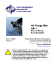
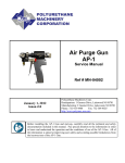
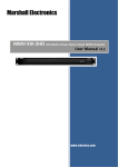
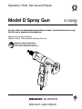
Operation, Parts, Service and Repair
Model D Spray Gun
311320G
ENG
For use with non-flammable polyurethane foams. For professional use only.
Not for use in explosive atmospheres.
See page 2 for model information.
1000 psi (7 MPa, 70 bar) Maximum Working Pressure
Important Safety Instructions
Read all warnings and instructions
in this manual. Save these instructions.
Models
Contents
Models . . . . . . . . . . . . . . . . . . . . . . . . . . . . . . . . . . . 2
Warnings . . . . . . . . . . . . . . . . . . . . . . . . . . . . . . . . . 3
Overall View . . . . . . . . . . . . . . . . . . . . . . . . . . . . . . . 5
Major Components . . . . . . . . . . . . . . . . . . . . . . . 5
Centerline Components . . . . . . . . . . . . . . . . . . . 6
Operation Basics . . . . . . . . . . . . . . . . . . . . . . . . . . . 7
Isocyanate Hazard . . . . . . . . . . . . . . . . . . . . . . . 7
Keep A and B Components Separate . . . . . . . . . 7
Grounding . . . . . . . . . . . . . . . . . . . . . . . . . . . . . . 7
Coupling Block . . . . . . . . . . . . . . . . . . . . . . . . . . 7
Air Hose Connection . . . . . . . . . . . . . . . . . . . . . . 9
Valving Rod Adjustment Screw . . . . . . . . . . . . . . 9
Air Cap Adjustment Valve . . . . . . . . . . . . . . . . . 10
Felt Wiper . . . . . . . . . . . . . . . . . . . . . . . . . . . . . 10
Initial Set Up . . . . . . . . . . . . . . . . . . . . . . . . . . . . . . 11
Daily Start-Up . . . . . . . . . . . . . . . . . . . . . . . . . . . . . 12
Daily Shutdown . . . . . . . . . . . . . . . . . . . . . . . . . . . 12
Pressure Relief Procedure . . . . . . . . . . . . . . . . . . 13
Spray Pattern Adjustment . . . . . . . . . . . . . . . . . . . 14
Maintenance . . . . . . . . . . . . . . . . . . . . . . . . . . . . . . 17
Gun Service Kits . . . . . . . . . . . . . . . . . . . . . . . . 17
Clean Spray Gun Procedure . . . . . . . . . . . . . . . 18
Repair . . . . . . . . . . . . . . . . . . . . . . . . . . . . . . . . . . . 19
Filter Screen Removal and Service . . . . . . . . . . 19
Clean Injection Slots . . . . . . . . . . . . . . . . . . . . . 20
Valving Rod Adjustment . . . . . . . . . . . . . . . . . . 21
Centerline Component Removal . . . . . . . . . . . . 22
Centerline Component Installation . . . . . . . . . . 24
Parts . . . . . . . . . . . . . . . . . . . . . . . . . . . . . . . . . . . . 26
Model D Spray Gun Assembly . . . . . . . . . . . . . . 26
Air Cylinder Assembly . . . . . . . . . . . . . . . . . . . . 30
Coupling Block Assembly . . . . . . . . . . . . . . . . . 31
Notes . . . . . . . . . . . . . . . . . . . . . . . . . . . . . . . . . . . . 32
Technical Data . . . . . . . . . . . . . . . . . . . . . . . . . . . . 33
Graco Standard Warranty . . . . . . . . . . . . . . . . . . . 34
Graco Information . . . . . . . . . . . . . . . . . . . . . . . . . 34
Models
2
Part No.
Description
Mix Module
295530
295531
295532
295533
D-55
D-55-RECIRC
D-62
D-70
296597
296597
296598
296599
311320G
Warnings
Warnings
The following general warnings are for the setup, use, grounding, maintenance, and repair of this
equipment. Additional, more specific warnings may be found throughout the body of this manual
where applicable. Symbols appearing in the body of the manual refer to these general warnings.
When these symbols appear throughout the manual, refer back to these pages for a description
of the specific hazard.
WARNING
PERSONAL PROTECTIVE EQUIPMENT
You must wear appropriate protective equipment when operating, servicing, or when in the
operating area of the equipment to help protect you from serious injury, including eye injury,
inhalation of toxic fumes, burns, and hearing loss. This equipment includes but is not limited to:
• Protective eyewear
• Clothing and respirator as recommended by the fluid and solvent manufacturer
• Gloves
• Hearing protection
TOXIC FLUID OR FUMES HAZARD
Toxic fluids or fumes can cause serious injury or death if splashed in the eyes or on skin,
inhaled, or swallowed.
• Read MSDS’s to know the specific hazards of the fluids you are using.
• Store hazardous fluid in approved containers, and dispose of it according to applicable
guidelines.
SKIN INJECTION HAZARD
High-pressure fluid from gun, hose leaks, or ruptured components will pierce skin. This may
look like just a cut, but it is a serious injury that can result in amputation. Get immediate surgical treatment.
• Do not point gun at anyone or at any part of the body.
• Do not put your hand over the spray tip.
• Do not stop or deflect leaks with your hand, body, glove, or rag.
• Do not spray without tip guard and trigger guard installed.
• Follow Pressure Relief Procedure in this manual, when you stop spraying and before
cleaning, checking, or servicing equipment.
311320G
3
Warnings
WARNING
FIRE AND EXPLOSION HAZARD
Flammable fumes, such as solvent and paint fumes, in work area can ignite or explode. To
help prevent fire and explosion:
• Use equipment only in well ventilated area.
• Eliminate all ignition sources; such as pilot lights, cigarettes, portable electric lamps, and
plastic drop cloths (potential static arc).
• Keep work area free of debris, including solvent, rags and gasoline.
• Do not plug or unplug power cords, or turn power or light switches on or off when flammable
fumes are present.
• Ground all equipment in the work area. See Grounding instructions.
• Use only grounded hoses.
• Hold gun firmly to side of grounded pail when triggering into pail.
• If there is static sparking or you feel a shock, stop operation immediately. Do not use
equipment until you identify and correct the problem.
• Keep a fire extinguisher in the work area.
EQUIPMENT MISUSE HAZARD
Misuse can cause death or serious injury.
• Do not operate the unit when fatigued or under the influence of drugs or alcohol.
• Do not exceed the maximum working pressure or temperature rating of the lowest rated
system component. See Technical Data in all equipment manuals.
• Use fluids and solvents that are compatible with equipment wetted parts. See Technical
Data in all equipment manuals. Read fluid and solvent manufacturer’s warnings. For complete information about your material, request MSDS forms from distributor or retailer.
• Check equipment daily. Repair or replace worn or damaged parts immediately with genuine
Graco/Gusmer replacement parts only.
• Do not alter or modify equipment.
• Use equipment only for its intended purpose. Call your Graco/Gusmer distributor for information.
• Route hoses and cables away from traffic areas, sharp edges, moving parts, and hot surfaces.
• Do not kink or over bend hoses or use hoses to pull equipment.
• Keep children and animals away from work area.
• Comply with all applicable safety regulations.
PRESSURIZED EQUIPMENT HAZARD
Fluid from the gun/dispense valve, leaks, or ruptured components can splash in the eyes or on
skin and cause serious injury.
• Follow Pressure Relief Procedure in this manual, when you stop spraying and before
cleaning, checking, or servicing equipment.
• Tighten all fluid connections before operating the equipment.
• Check hoses, tubes, and couplings daily. Replace worn or damaged parts immediately.
4
311320G
Overall View
Overall View
Major Components
Spring Retainer Case
Valving Rod Closure Spring
Valving Rod Positioner
Valving Rod
Adjustment Screw
Valving Rod Stop Bar
Valving Rod
Gun Block
Piston Rod
Trigger
Air Cap Adjustment Valve
Coupling Block
Coupling Block
Mounting Screw
FIG. 1: Major Components
311320G
5
Overall View
Centerline Components
Gun Block
Mounting Screw
Screen Screw
O-Ring
Closure
Screw
Valving Rod
Assembly
A-Iso Check Valve
Seal
Felt Wiper Retainer
Gun Block
R-Resin Check Valve
Screen Mounting Screw
Screen
Snap Ring
Mixing Chamber Case
Air Cap
Coupling Block Gaskets
FIG. 2: Centerline Components
6
311320G
Operation Basics
Operation Basics
To prevent accidental gun operation, always
disconnect air supply before servicing gun or
anytime gun is not in use.
Isocyanate Hazard
Spraying materials containing isocyanates
creates potentially harmful mists, vapors,
and atomized particulates.
Read material manufacturer’s warnings and
material MSDS to know specific hazards
and precautions related to isocyanates.
Prevent inhalation of isocyanate mists,
vapors, and atomized particulates by providing sufficient ventilation in the work area. If
sufficient ventilation is not available, a supplied-air respirator is required for everyone in
the work area.
To prevent contact with isocyanates, appropriate personal protective equipment, including chemically impermeable gloves, boots,
aprons, and goggles, is also required for
everyone in the work area.
Grounding
Check your local electrical code and proportioner manual for detailed grounding instructions.
Ground the spray guy through connection to a
Graco-approved grounded fluid supply hose.
Coupling Block
Install Coupling Block
1. Inspect coupling block gaskets for damage
and wear. Replace if necessary.
2. With gaskets in place, fit coupling block to
gun block.
3. Insert coupling block mounting screw and
tighten securely with 5/16 in. nut driver.
Coupling Block
Gaskets
Keep A and B Components
Separate
CAUTION
To prevent cross-contamination of the gun’s
wetted parts, do not interchange A component (isocyanate) and B component (resin)
parts. The gun is shipped with the A side on
the left.
311320G
Coupling Block
Mounting Screw
FIG. 3: Coupling Block
7
Operation Basics
Manual Valves
Triggering gun with manual valves closed
may cause crossover if gun ports contain
residual chemical.
Never open manual valves unless coupling
block is secured to gun or exit port is directed
into flush pail.
1. Open manual valves using 5/16 in. nut
driver; turn manual valves counterclockwise approximately three full turns. Do not
open until it bottoms out.
2. Close manual valves by turning fully clockwise.
Remove Coupling Block
To prevent release of pressurized chemical,
close both manual valves before removing
coupling block.
1. Disconnect air hose.
2. Close both manual valves.
3. Remove coupling block mounting screw
(FIG. 3).
4. Separate coupling block from gun. Do not
lose gaskets.
5. Use gun cleaner to wipe clean mating surface of gun block and coupling block. Cover
exposed opening with grease.
Manual Valves
FIG. 4: Manual Valves
8
311320G
Operation Basics
Air Hose Connection
To CONNECT air hoses, pull back sleeve of
female fitting, insert male fitting and slide
sleeve forward to secure connection.
To DISCONNECT air hoses, pull back sleeve
of female fitting and remove male fitting.
Pull Sleeve
Valving Rod Adjustment
Screw
Use to regulate amount of valving rod travel
when gun trigger is depressed with air supply
connected. Turn clockwise to decrease travel,
and counterclockwise to increase travel.
1. Use 5/64 in. hex key wrench to loosen friction lock.
2. Turn adjustment screw as required and
tighten friction lock until screw no longer
easily turns by hand.
3. Check friction lock periodically and tighten
as required to prevent screw from slipping
during operation.
Friction Lock
FIG. 5: Air Hose Connection
FIG. 6: Valving Rod Adjustment Screw
311320G
9
Operation Basics
Air Cap Adjustment Valve
3. Use 5/16 in. open-end wrench to tighten
retainer another half turn.
Use to control amount of air that passes
through air cap and over mixing chamber tip.
Airflow helps keep tip free of sprayed chemical.
Too much air may distort spray pattern and
create overspread. Too little air will not properly clean end of valving rod.
To OPEN valve, turn knob approximately 1/8
turn counterclockwise.
To CLOSE valve, turn knob fully clockwise.
FIG. 8: Felt Wiper
Clean Felt Wiper
1. Insert nozzle of flush can into holes of felt
wiper.
Open
2. Saturate felt with gun cleaner.
Close
FIG. 7: Air Valve Adjustment
Felt Wiper
Adjust Felt Wiper
1. Use 5/16 in. open-end wrench to loosen
retainer slightly.
2. Slowly tighten it by hand until it seats
against rear packings in mixing chamber.
10
311320G
Initial Set Up
Initial Set Up
1. Remove coupling block from gun.
2. Check valving rod clearance in closed position. Rod should extend approximately 1/32
in. (1 mm) beyond tip of mixing chamber. If
it does not, see Valving Rod Adjustment
procedure, page 21.
1/32 in.
FIG. 9: Valving Rod (Closed Position)
b. Open each manual valve to allow
trapped air to escape. Bleed each side
until chemical is free of air.
c. Close both manual valves.
9. Use clean cloth soaked in gun cleaner to
wipe clean coupling block and its mating
surfaces.
CAUTION
To avoid accumulation of dirt and other contaminants, do not apply grease to mating
surfaces of coupling block.
3. Adjust valving rod travel to initial setting.
10. Install coupling block to gun block.
a. Loosen friction lock. Turn valving rod
adjustment screw clockwise until it
stops.
11. Proceed with Daily Start-up procedure or
Shutdown procedure as required.
b. Turn valving rod adjustment screw 11
turns counterclockwise.
4. Connect air supply hose to gun.
5. Connect A-isocyanate hose (red-taped) to
notched fitting on coupling block. Then connect R-resin hose (blue-taped) to fitting
without notches on coupling block.
6. Close both manual valves.
7. Pressurize the A and R chemical hoses
and check for leaks. (See Proportioning
Unit manual.)
8. Bleed air from chemical hoses:
a. Hold coupling block with exit ports
pointed into disposable container.
311320G
11
Daily Start-Up
Daily Start-Up
Ensure gun is attached to coupling block and
air hose, and the proportioning unit is at
desired temperature and pressure.
1. Connect air supply to gun, page 9.
2. Adjust air cap valve, page 10.
3. Saturate felt in felt wiper with gun cleaner
using flush can.
4. Trigger gun multiple times to ensure valving
rod moves the full travel quickly and freely.
Daily Shutdown
Follow when gun is out of service for any
length of time. Daily disassembly of gun for
cleaning is not recommended if it has been
operating properly. However, if you remove
the gun from the coupling block, flush and
clean thoroughly.
1. Follow Pressure Relief Procedure, page
13.
2. Shut down proportioning unit as required.
CAUTION
Sluggish valving rod action may result in valving rod
sticking in open position when fluid pressure is
applied. Always have a 5/16 in. nut driver available to
quickly close manual valves on coupling block.
5. Open both manual valves, page 8.
6. Test spray on disposable surface and
adjust spray pattern as needed. (See Spray
Pattern Adjustment procedure, page 14.)
Do not exceed 1000 psi (7 MPa, 70 bar)
maximum fluid working pressure even in
static de-triggered conditions, or check
valve damage may result.
12
311320G
Pressure Relief Procedure
Pressure Relief Procedure
Relieve pressure before cleaning or repairing
gun.
1. Close both manual valves.
Manual Valves
2. Trigger gun once onto waste area to relieve
fluid pressure in front end of gun.
3. Disconnect gun air supply, page 9.
4. If gun is removed from coupling block, follow Clean Spray Gun Procedure, page 18.
If fluid in hose and proportioner is still under
pressure, follow Pressure Relief Procedure in
proportioner manual
To relieve pressure in hose after gun is
removed, place fluid manifold over containers,
facing away from you. Very carefully open
fluid valves. Under high pressure, fluid will
spray sideways from fluid ports.
311320G
13
Spray Pattern Adjustment
Spray Pattern Adjustment
This adjustment may create a large mass
“bun” of urethane foam. Very high temperatures created by chemical reaction inside a
bun may not dissipate after outside surface
has cooled. A large bun may continue to react
for several hours after spraying until flash
(burning) point of foam is reached. ALWAYS
break buns into smaller pieces so heat can
escape.
1. Check valving rod clearance in closed position. Rod should extend approximately 1/32
in. (1 mm) beyond tip of mixing chamber. If
it does not, see Valving Rod Adjustment
procedure, page 21.
from retainer case by 1/4-turn increments in counterclockwise direction.
c. Point of valving is reached when chemical stream mists as shown in FIG. 11.
1/32 in.
FIG. 10: Valving Rod (Closed Position)
2. Adjust valving rod travel to initial setting.
a. Loosen friction lock. Turn valving rod
adjustment screw clockwise until it
stops.
b. Turn valving rod adjustment screw 11
times counterclockwise.
3. Locate point of valving:
a. Aim gun at disposable target.
b. Dispense short (1 second) bursts
toward target while simultaneously withdrawing valving rod adjustment screw
14
FIG. 11: Point of Valving
4. Adjust spray pattern. Note position of notch
in hexhead of adjustment screw, then back
screw out counterclockwise the number of
turns specified in Table 1. Notice spray pat-
311320G
Spray Pattern Adjustment
tern opens as adjustment is made (FIG.
12).
FIG. 14: Split Pattern
FIG. 12: Opening Spray Pattern
5. Fine tune spray pattern:
a. After you back out adjustment screw,
make fine adjustments (1/8 turns or less
in either direction as required) to obtain
pattern shown in FIG. 13. Moving the
screw out beyond this point may cause
the pattern to split, as shown in FIG. 14.
FIG. 13: Desired Pattern
311320G
b. If full-round pattern cannot be achieved,
ensure that material temperature and
spray pressure are correct. If pattern
remains closed upon reaching maximum specified number of turns out from
point of valving, material temperature is
too low
c. If pattern splits or has hollow center,
even with the adjustment screw at minimum number of turns from point of valving, material temperature is too high.
Refer to FIG. 12.
d. After reaching satisfactory spray pattern, note temperatures at proportioner
and hose, and position of notch on the
adjustment screw. As spraying proceeds, pattern may occasionally streak
or change. If this happens, inspect
chamber tip and remove any build-up of
solid foam with wooden stick or brass
wire brush.
15
Spray Pattern Adjustment
e. If buildup recurs shortly after cleaning
tip, remove air cap and ensure inside is
clean.
Reinstall air cap and ensure airflow is properly
set.
If no buildup occurred on air cap, check the following items in this order and readjust if necessary:
•
Check Valving Rod Adjustment
Screw/Sleeve setting.
Turns Out From Point of
Valving
Chamber
Minimum
Maximum
46-800
46-810
55-776
1/2 turn
1/2 turn
1 3/4 turns
2 turns
2 turns
2 5/8 turns
62
2 turns
3 turns
70
2 turns
3 turns
78-851
2 turns
3 turns
•
Check hose temperature setting.
•
Check primary heater temperature setting.
•
Ensure spray pressures between chemicals are balanced. If they are not, refer to
Troubleshooting section of Proportioning
Unit Operation Manual for the proportioner
in use.
•
Ensure flow of air to air cap is adequate but
not excessive.
Recommended
Distance of Gun
from Surface
Pattern Size
12 in. (304-8 mm)
12 in. (304-8 mm)
18 to 20 in. (457.2
to 508 mm)
18 to 20 in. (457.2
to 508 mm)
18 to 20 in. (457.2
to 508 mm)
24 in. (609.6 mm)
6 in. (152.4 mm)
6 in. (152.4 mm)
8 in. (203.2 to
228.6 mm)
8 to 9 in. (203.2
to 228.6 mm)
10 to 12 in. (254
to 304.8 mm)
14 in. (355.6 mm)
Table 1: Valving Rod Adjustment for Standard Mixing Chambers
16
311320G
Maintenance
Maintenance
Gun Service Kits
Use either the 1-Quart Gun Service Kit
(296980) or 3-Gallon Gun Service Kit (296981)
to perform daily flushing of spray gun without
disassembly.
FIG. 16: 3-Gallon Gun Service Kit
For more information about the 3-Gallon Gun
Service Kit, see manual 311341.
FIG. 15: 1-Quart Gun Service Kit
For more information about the 1-Quart Gun
Service Kit, see manual 311340.
311320G
17
Maintenance
Clean Spray Gun Procedure
Thoroughly flush gun block with gun cleaner
before removing valving rod or mixing components from gun block. Also allow chemicals in
spray gun to cool before cleaning.
12. Clean screens, check valves and screen
screw. See Filter Screw Removal and Service procedure, page 19.
Inspect air cap, mixing chamber, and gun
block for build up of material and clean as
required.
Do not use metal cleaning devices to clean
plastic components.
This procedure makes use of the 1-Quart or
3-Gallon Gun Service Kit.
1. Close both manual valves.
2. Remove gun from coupling block.
3. Attach service block of gun service kit to
spray gun, and then tighten using 5/16 in.
nut driver.
4. Pressurize container to 100 psi.
5. Open one manual valve on service block.
6. Trigger gun while holding against a
grounded waste container until there is a
fine, unobstructed mist of gun cleaner.
7. Release trigger of gun and 1-quart kit, and
close manual valves on service block.
8. Repeat steps 5-7 for other side of gun.
9. After initial cleaning, remove air cap and
flush a second time to ensure thorough
cleaning.
10. Remove service block of gun service kit
from spray gun.
11. Disconnect air supply.
18
311320G
Repair
Repair
Shut down proportioner and allow chemicals
to cool before performing any repair procedures.
Clean Center Line Components using Gun
Service Kit prior to performing any repair procedures.
Filter Screen Removal and
Service
1. Perform Pressure Relief Procedure (page
13) and Clean Spray Gun Procedure, page
18.
2. Unthread screen mounting screw. Remove
screen mounting screw and filter screen
assembly from gun block.
Screen Screw
4. Clean and inspect screen cavity. If particles
are visible, remove with cleanout drills and
flush thoroughly with gun cleaner.
CAUTION
Any remaining material in cavity on down
stream side of screen will clog mixing chamber.
5. Inspect seal, and replace if worn or damaged.
6. Reinstall filter screen assembly. With seal
in place, install screen and retainer clip-on
screen screw.
Seal
Screen
Snap Ring
7. Install screen assembly to gun block.
Ensure screw is tight to prevent leakage.
8. Flush gun after cleaning cavity and screen.
See Clean Spray Gun Procedure, page 18.
Mounting Screw
FIG. 17: Filter Screen Assembly
3. Remove screen screw retainer (snap ring
at end of screw) and screen. If screen is
dirty and clogged, replace it.
311320G
19
Repair
Clean Injection Slots
1. Perform Pressure Relief Procedure (page
13) and Clean Spray Gun Procedure, page
18.
7. Flush injection slots. With valving rod in
open position, flush each injection slot with
gun cleaner. Press flush can needle firmly
into cleanout hole to create seal. Continue
until gun cleaner sprays out chamber tip.
2. Remove check valves.
8. Inspect and clean check valves, page 22.
A-Iso Check Valve
(tall hexhead)
9. Install tall hexhead check valve on Isocyanate side, and short hexhead on Resin
side.
10. Adjust valving rod adjustment screw one
turn clockwise.
Clean-out Port
(both sides)
R-Resin Check Valve
(short hexhead)
FIG. 18: Check Valves
3. Inspect check valves to ensure sleeve is
secured, and place check valves in separate containers of gun cleaner.
4. Flush cleanout ports with gun cleaner.
5. Turn valving rod adjustment screw one full
turn counterclockwise to ensure valving rod
will be withdrawn completely past injection
slot.
6. Clean mixing chamber injection slots. With
air supply connected to gun, depress and
hold trigger to keep valving rod in open
position. Insert appropriate cleanout spade
into cleanout hole and mixing chamber.
CAUTION
To prevent damage to chamber, do not
release trigger while cleanout spade is in
chamber slot.
20
311320G
Repair
Valving Rod Adjustment
In closed position, valving rod should extend
approximately 1/32 in. (1 mm) beyond tip of
mixing chamber. If it does not, follow this procedure:
5. Remove valving rod. Push back firmly on
piston rod until end of Stop Bar emerges
from cylinder.
Positioner
1/32 in.
FIG. 19: Valving Rod (Closed Position)
1. Perform Pressure Relief Procedure (page
13) and Clean Spray Gun Procedure, page
18.
2. Disconnect air supply from gun.
3. Remove spring retainer case. Firmly grasp
spring retainer case, push in and rotate
counterclockwise. Pull spring out of air cylinder.
Stop Bar
FIG. 21: Valving Rod Removal
6. Loosen stop bar from positioner. Turn positioner to adjust length of valving rod as
required. Retighten stop bar against positioner.
7. Replace valving rod, spring, and spring
retainer case. Grasp firmly, push in, and
turn clockwise to lock in place.
Spring Retainer Case
8. Adjust felt wiper and soak with gun cleaner.
9. Connect air supply to gun.
Spring
FIG. 20: Retainer Case Removal
10. Check action of valving rod. With manual
valves closed, press trigger several times
and ensure valving rod moves freely.
If you have encountered no problems, spray
gun is ready for test spray. Follow Daily
Start-up procedure (page 12) and Spray Pattern Adjustment procedure (page 14).
4. Loosen felt wiper retainer 2-3 turns (DO
NOT REMOVE).
311320G
21
Repair
Centerline Component
Removal
tool into rear of gun block and tap with
hammer until chamber ejects. Place chamber in gun cleaner.
Mixing Chamber
Refer to Figure 2 to view centerline components.
1. Perform Pressure Relief Procedure (page
13) and Clean Spray Gun Procedure, page
18.
2. Remove air cap by hand, turning it counterclockwise.
Chamber
Knockout
Tool
FIG. 22: Mixing Chamber Removal
3. Remove screen screw assembly. Flush and
place in gun cleaner.
4. Remove check valves. Flush and place in
gun cleaner.
5. Flush screen screw and check valve ports.
6. Remove spring retainer case by firmly
grasping knob of case. Push in and rotate
counterclockwise to remove from air cylinder. Pull spring out of air cylinder.
7. Loosen felt wiper retainer 2-3 turns. DO
NOT REMOVE.
8. Remove valving rod. Push back firmly on
piston rod until end of valving rod stop bar
emerges from cylinder.
CAUTION
Matching tapers on mixing chamber and
center hole in gun block are machined to an
exact fit to hold chambers in place and create a leak-proof seal. When handling or
cleaning these parts be careful not to damage finish. Do not use metal tools to clean
these parts.
12. Remove closure screw in top of gun block.
Place screw in gun cleaner and clean entire
gun using appropriate cleanout tools and
brass brushes. Then flush thoroughly with
gun cleaner.
13. Disassemble check valve assemblies.
9. Remove gun block from frame.
Screw
10. Unscrew felt wiper assembly from rear of
mixing chamber. Keep rear of mixing chamber in upright position to prevent possible
loss of internal chamber parts. Ensure
brass retaining sleeve is not stuck to felt
wiper. Place wiper assembly in gun
cleaner.
11. Remove mixing chamber. Hold gun block in
one hand with chamber tip pointing into
your palm. Insert mixing chamber knockout
22
Sleeve
Ball and Spring
FIG. 23: Check Valves
311320G
Repair
a. Remove ball and spring assembly. Hold
ball and unscrew assembly. If dirt or
material build-up prevents complete
removal of the spring, screw it back in.
Soak assembly in gun cleaner and try to
remove it again. If ball and spring
assembly cannot be removed undamaged, replace it.
b. Use check valve cleanout drill to clean
inside of closure screw. Insert the flattened end of cleanout drill into opening
at end of screw, avoiding spurs in the
closure screw. Do not spin drill until the
flat on the drill has cleared spurs. Spin
drill with your fingers to loosen any
buildup, then remove drill and flush
inside of screw with gun cleaner. Next,
check area where ball seats for damage. Also check sleeve for damage; it
should fit tightly on the end of the screw.
If there is damage or if the sleeve fits
loosely, replace it. Replace sleeve if
check valve can be threaded all the way
into gun block by hand. A good check
valve requires the use of a 5/16 in. nut
driver to make the last 1/4 turn, compressing the sleeve. This compression
is required to create an internal seal in
the gun block.
c. Remove damaged check valve sleeve.
Remove ball and spring. Insert check
valve into check valve sleeve removal
block (FIG. 24). While holding block, and
keeping pressure on head of check
valve, slice check valve sleeve with
razor knife at a 10 - 15 degree angle relative to the plane of removal block.
Remove check valve from block and
peel sleeve off. If check valve sleeve
remains in gun block after removing
311320G
check valve, use extractor tool to
remove sleeve. Insert threaded end of
tool into cleanout port and, while pressing tool into gun block, turn it clockwise
several times. Withdraw tool from gun
block; sleeve should slide out with tool.
Check Valve Sleeve
Insert Check Valve
FIG. 24: Sleeve Removal Block
d. Insert spring assembly into check valve
and turn the screw clockwise. When the
spring is fully inserted, stem will jump
over spurs in screw and make clicking
sound. Ensure ball fully seats in check
valve. If not, or ball is damaged, replace
with new ball and spring assembly.
14. Remove retaining ring, washer, and felt
wiper from retainer. Flush retainer with gun
cleaner, insert new felt wiper and washer,
then install retaining ring. Loosely thread
felt wiper retainer into rear of mixing chamber (DO NOT TIGHTEN). If not installing to
gun block, store assembly in plastic vial
with corresponding cleanout spade.
23
Repair
Centerline Component
Installation
All gun block parts must be clean and free
of damage before installation.
1. Remove felt wiper assembly from rear of
mixing chamber.
2. Ensure internal mixing chamber parts are
in place.
3. Insert chamber into gun block. Align keyway in chamber with pin protruding from
top of hole in block.
5. Thread felt wiper assembly into back of
mixing chamber. Do not tighten.
CAUTION
Failure to install felt wiper in rear of chamber
allows internal chamber parts to fall out
when chamber is tapped into place.
6. With rear of gun block facing palm of your
hand, place mixing chamber insertion block
over nose of chamber so it rests squarely
on the chamber flange. Firmly tap insertion
block with hammer until flange of chamber
is flush with face of gun block (FIG. 27).
Chamber Insertion Block
FIG. 27: Chamber Seating
FIG. 25: Mixing Chamber Insertion
4. Press chamber into block so that flange is
1/32 - 1/16 in. above face of gun block.
1/32 in.
1/16 in.
FIG. 26: Chamber Positioning
24
7. With o-ring in place on underside of gun
frame, assemble block to frame.
8. Install valving rod assembly. If using new
felt wiper, push valving rod through felt with
retainer case off chamber. Remove felt
wiper and any felt buildup on tip of rod.
Install wiper, hand tighten into rear of
chamber in gun block. Then insert valving
rod through piston in air cylinder, guiding it
through center of felt wiper retainer. Use
firm pressure to carefully push valving rod
into mixing chamber until piston of air cylinder bottoms out.
9. Check valving rod clearance. If it does not
extend approximately 1/32 in. (1mm)
beyond tip of mixing chamber, see Valving
Rod Adjustment, page 21.
311320G
Repair
10. Replace valving rod spring and spring
retainer case. Grasp knob, push in, and
turn clockwise to lock in place.
11. Replace air cap.
12. Replace check valves and screen screw
assembly.
13. Replace closure screw in top of gun block.
14. Mount gun onto coupling block.
15. Connect air supply to gun.
16. Adjust felt wiper and soak felt with gun
cleaner.
17. Close manual valves and press trigger several times to ensure valving rod moves
freely.
311320G
25
Parts
Parts
Model D Spray Gun Assembly
M
L
K
AE
AF
R
X
Z
N
B
D
V
A
AM
U
AS
S
D
AL
AP
G
E
W
J
H
Y
AG
AC
F
AJ
AD
AB
AK
AT
D
T
B
AA
AN
C
AR
AQ
26
311320G
Parts
Model D Spray Gun Assembly
Ref.
No.
A
B
C
Part No.
295591
295185
296090
D
296091
E
296614
F
296615
G
H
J
K
L
M
295592
296616
296617
N
295171
R
S❄
T
U
296618
V
296622
296623
295595
296624
W
X
296620
296621
Description
Qty.
Hex nipple, 1/8 in. MPT, steel
1
Mounting screw, 1/2 in. LG
2
Ball and spring assembly
(pack of 10)
Check valve sleeve
(pack of 10)
Kit, A-check valve, includes C
and D (pack of 10)
Kit, R- check valve, includes C
and D (pack of 10)
Roll pin, 1/16 x 5/16 in. SST
1
Snap ring (see J)
1
Trigger button; includes H
1
Valving rod (see Table 1)
1
Valving rod positioner (see M)
1
Valving rod stop bar;
1
includes L
Valving rod stop adjustment
1
screw
Valving rod closure spring
1
Air valve
1
Pipe nipple
1
Screen screw seal
(pack of 10)
Screen-80 mesh (pack of 10)
Screen-80 mesh (pack of 50)
Snap ring
1
Kit, gun block screen screw
1
(includes U, V, W)
Ref.
No. Part No.
296611
Y
297139
Z
AA
111450
296625
AB
296121
AC
AD
AE
AF
AG
AJ
AK
AL
AM
AN
AP
AQ
AR
AS
AT
295590
296629
296633
295182
295183
296126
15B772
295482
295596
295597
103557
100030
Description
Qty.
Felt wiper assembly (includes
retainer, wiper, washer) (pack
of 5)
Felt wiper (pack of 15) and
retainer washers (pack of 3)
O-ring
1
Coupling block gasket
(pack of 10)
D gun block, complete
1
(includes G, AA, AP)
1
Mixing chamber (includes Y)
(see Table 1)
Gun frame
Spring retainer case (includes
N)
Air cylinder (see page 30)
Needle valve and packing kit
Needle valve body
Air cap (see Table 1)
Retainer nut/dust cover
Gun air tube, includes D
(qty. 2)
Air hose
Closure screw
Coupler plug
Coupler
O-ring
Fitting
1
1
1
1
1
1
1
1
1
1
1
1
1
❄ Purchase Air Valve Repair Kit 296125 (purchase separately). Includes Needle Valve Packing.
★ Not shown.
d
Mixing
Chamber
(AC)
Air Cap
(AK)
Cleanout
Spade★
Coupling
Block (see
page 31)
Tool Kit★
Model No.
Description
Valving
Rod (K)
295530
D-55
296579
296597
296634
295934
295887
296636
295531
D-55RECIRC
296579
296597
296634
295934
295884
296636
295532
D-62
296580
296598
296634
295935
295887
296636
295533
D-70
296581
296599
296635
295935
295887
296636
Table 1: Model D Gun Assembly, Parts by Model Number
311320G
27
Parts
Mixing Chamber Size
Reference Size
46
55
62
70
78
K (valving rod)
296578
296579
296580
296581
296582
296597 (N)
296586 (L)
296592 (L-LM)
296598 (N)
296587 (L)
296599 (N)
296588 (L)
296600 (N)
297592 (L)
AC (chamber)
296594 (N-800)
296595 (N-810)
296584 (L-800)
296590 (L-800-LM)
296585 (L-810)
296591 (L-810-LM)
AK (air cap)
296838
296634
296634
296635
296635
Cleanout
spade
297007
(pack of 2)
295934
(pack of 2)
295935
(pack of 2)
295935
(pack of 2)
295935
(pack of 2)
Table 2: Model D Gun Assembly, Parts by Mixing Chamber Size
28
311320G
Parts
Standard Mixing Chambers
Six standard mixing chambers are available. The following table provides a general description
about use and operational performance of each chamber. Actual pattern sizes and outputs
achieved may vary depending on material viscosity, hose length, condition of equipment, environment, working pressure, and additional factors.
Designed for operation in confined areas and for spraying 3/8 to 1/2-in. (.7 to
46 Size
1.3 cm) thicknesses. Gun may be held within 4 in. (10.2 cm) of target without
blowing away freshly applied foam. Pattern diameter is approximately 4 in.,
296594 (N-800)
with gun 4-in. (10.2-cm) distance from target. Output is approximately 2 to
296584 (L-800)
296590 (L-800-LM) 3-1/4 pounds/min. (.9 to 1.5 kg/min.).
46 Size
For the same uses as above. These chambers have an increased output of
approximately 3 to 4-1/2 pounds/min. (1.4 to 2.0 kg/min.).
296595 (N-810)
296585 (L-810)
296591 (L-810-LM)
55 Size
296597 (N)
296586 (L)
296592 (L-LM)
62 Size
296598 (N)
296587 (L)
70 Size
296599 (N)
296588 (L)
78 Size
296600 (N)
297592 (L)
311320G
Designed for stud areas of trucks and small- to medium-sized wall applications. Pattern diameter is about 8 in. (20.3 cm), with gun 18 to 20 in. (45.7 to
50.8 cm) from target. Output is approximately 6 to 8 pounds/min. (2.7 to 3.6
kg/min.).
For very large area applications. Pattern diameter is about 9 in. (22.9 cm)
with gun 18 to 20 in. (45.7 to 50.8 cm) from target. Output range is about 7
to 10 pounds/min. (3.2 to 4.5 kg/min.).
For very large area applications. Pattern diameter is about 10 in. (25.4 cm)
with gun 18 to 20 in. (45.7 to 50.8 cm) from target. Output range is about 9
to 12 pounds/min. (4.1 to 5.4 kg/min.).
For very large area applications. Pattern diameter is about 14 in. (35.6 cm)
with gun 24 in. (60.9 cm) from target. Output range is about 13-1/2 to 16-1/2
pounds/min. (6.1 to 7.5 kg/min.).
29
Parts
Air Cylinder Assembly
Part Number 296632
B
C
F
K
J
D
A
H
E
G
Ref.
No. Part No. Description
A❄ 107083 O-ring, fluoroelastomer
B
295494 Pan head machine screw,
8-32 x 3/16 in.
C
295177 Front head blank
D❄ 296627 U-cup (pack of 5)
E❄ 296628 U-cup (pack of 5)
F
295178 Cylinder
G❄ 296631 Wear ring
H
295179 Buttonhead cap screw
J
295484 Piston assembly
K▲ 295492 Label, warning
Qty.
1
1
1
1
1
3
1
1
❄ Parts included in Air Cylinder Seal Kit 296725 (purchase separately)
▲ Replacement Danger and Warning labels, tags, and cards are available at no cost.
30
311320G
Parts
Coupling Block Assembly
Model 295887
E
D
D
A
A
G
B
C
B
G
F
C
F
G
E
D
A
E
A
Model 295884
Model 295887 (Standard)
Model 295884 (Recirc)
Ref.
No.
A
B
C
D
Part No.
295662
295888
295889
296626
E
F
G
295619
295693
295886
Ref.
No. Part No.Description
A
295889 A-swivel fitting
B
296626 Manual valve assembly (pack
of 2)
C
295619 Mounting screw
D
295693 Pipe plug
E
112307 Street elbow
F
295886 Coupling block
G
295888 R-swivel fitting
311320G
Description
Qty.
Flush seal pipe plug, 1/8 in.
2
R-swivel fitting
1
A-swivel fitting
1
Manual valve assembly (pack
of 2)
Mounting screw, 15/16 in.
1
Flush seal pipe plug, 1/36 in.
2
Coupling block
1
Qty.
2
1
2
2
1
2
31
Notes
Notes
32
311320G
Technical Data
Technical Data
Category
Data
Maximum Fluid Working Pressure
Maximum Air Inlet Pressure
Minimum Air Inlet Pressure
Maximum Output (flow rate)
Minimum Output (flow rate)
Air Inlet Size
A Component (ISO) Inlet Size
R Component (Resin) Inlet Size
Length
Height
Width (without coupling block)
Weight
Wetted Parts
1000 psi (7 MPa, 70 bar)
100 psi (0.75 MPa, 7.5 bar)
90 psi (0.6 MPa, 6 bar)
16 lbs/min (7.3 kg/min) *
2 lbs/min (0.9 kg/min) *
x npt
-5 JIC; 1/2-20 UNF
-6 JIC; 9/16-18 UNF
9.25 in. (24 cm)
8 in. (20 cm)
2.4 in. (6 cm)
3 lbs. (1.4 kg)
Stainless steel, carbon steel, brass, nylon, acetal, PTFE
* Theoretical: actual results will vary with operating conditions
311320G
33
Graco Standard Warranty
Graco warrants all equipment referenced in this document which is manufactured by Graco and bearing its name to be free from defects in
material and workmanship on the date of sale to the original purchaser for use. With the exception of any special, extended, or limited warranty
published by Graco, Graco will, for a period of twelve months from the date of sale, repair or replace any part of the equipment determined by
Graco to be defective. This warranty applies only when the equipment is installed, operated and maintained in accordance with Graco’s written
recommendations.
This warranty does not cover, and Graco shall not be liable for general wear and tear, or any malfunction, damage or wear caused by faulty
installation, misapplication, abrasion, corrosion, inadequate or improper maintenance, negligence, accident, tampering, or substitution of
non-Graco component parts. Nor shall Graco be liable for malfunction, damage or wear caused by the incompatibility of Graco equipment with
structures, accessories, equipment or materials not supplied by Graco, or the improper design, manufacture, installation, operation or
maintenance of structures, accessories, equipment or materials not supplied by Graco.
This warranty is conditioned upon the prepaid return of the equipment claimed to be defective to an authorized Graco distributor for verification of
the claimed defect. If the claimed defect is verified, Graco will repair or replace free of charge any defective parts. The equipment will be returned
to the original purchaser transportation prepaid. If inspection of the equipment does not disclose any defect in material or workmanship, repairs will
be made at a reasonable charge, which charges may include the costs of parts, labor, and transportation.
THIS WARRANTY IS EXCLUSIVE, AND IS IN LIEU OF ANY OTHER WARRANTIES, EXPRESS OR IMPLIED, INCLUDING BUT NOT LIMITED
TO WARRANTY OF MERCHANTABILITY OR WARRANTY OF FITNESS FOR A PARTICULAR PURPOSE.
Graco’s sole obligation and buyer’s sole remedy for any breach of warranty shall be as set forth above. The buyer agrees that no other remedy
(including, but not limited to, incidental or consequential damages for lost profits, lost sales, injury to person or property, or any other incidental or
consequential loss) shall be available. Any action for breach of warranty must be brought within two (2) years of the date of sale.
GRACO MAKES NO WARRANTY, AND DISCLAIMS ALL IMPLIED WARRANTIES OF MERCHANTABILITY AND FITNESS FOR A
PARTICULAR PURPOSE, IN CONNECTION WITH ACCESSORIES, EQUIPMENT, MATERIALS OR COMPONENTS SOLD BUT NOT
MANUFACTURED BY GRACO. These items sold, but not manufactured by Graco (such as electric motors, switches, hose, etc.), are subject to
the warranty, if any, of their manufacturer. Graco will provide purchaser with reasonable assistance in making any claim for breach of these
warranties.
In no event will Graco be liable for indirect, incidental, special or consequential damages resulting from Graco supplying equipment hereunder, or
the furnishing, performance, or use of any products or other goods sold hereto, whether due to a breach of contract, breach of warranty, the
negligence of Graco, or otherwise.
FOR GRACO CANADA CUSTOMERS
The Parties acknowledge that they have required that the present document, as well as all documents, notices and legal proceedings entered into,
given or instituted pursuant hereto or relating directly or indirectly hereto, be drawn up in English. Les parties reconnaissent avoir convenu que la
rédaction du présente document sera en Anglais, ainsi que tous documents, avis et procédures judiciaires exécutés, donnés ou intentés, à la suite
de ou en rapport, directement ou indirectement, avec les procédures concernées.
Graco Information
For the latest information about Graco products, visit www.graco.com.
TO PLACE AN ORDER, contact your Graco distributor or call to identify the nearest distributor.
Phone: 612-623-6921 or Toll Free: 1-800-328-0211, Fax: 612-378-3505
All written and visual data contained in this document reflects the latest product information available at the time of publication.
Graco reserves the right to make changes at any time without notice.
Original instructions. This manual contains English. MM 311320
Graco Headquarters: Minneapolis
International Offices: Belgium, China, Japan, Korea
GRACO INC. P.O. BOX 1441 MINNEAPOLIS, MN 55440-1441
Copyright 2006, Graco Inc. is registered to ISO 9001
www.graco.com
Revised 02/2010