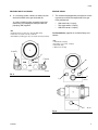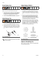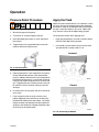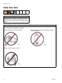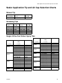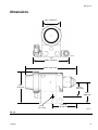
1
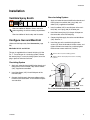
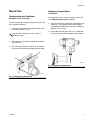
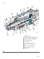
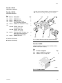
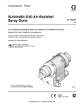
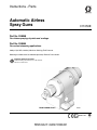
Instructions - Parts
Automatic Airless
Spray Guns
311053E
Part No. 288048
For airless spraying of paints and coatings.
Part No. 288554
For sealant streaming applications.
4000 psi (28 MPa, 280 bar) Maximum Working Fluid Pressure
Mounting manifolds must be ordered separately. Refer to Parts section.
Important Safety Instructions
Read all warnings and instructions in this manual.
Save these instructions.
Model 288048 Shown
TI8089a
II 2 G c T6
Related Manuals
Contents
Related Manuals . . . . . . . . . . . . . . . . . . . . . . . . . . . 2
Warnings . . . . . . . . . . . . . . . . . . . . . . . . . . . . . . . . . 3
Installation . . . . . . . . . . . . . . . . . . . . . . . . . . . . . . . . 5
Ventilate Spray Booth . . . . . . . . . . . . . . . . . . . . . 5
Configure Gun and Manifold . . . . . . . . . . . . . . . . 5
Install Air Fittings . . . . . . . . . . . . . . . . . . . . . . . . . 6
Ground System . . . . . . . . . . . . . . . . . . . . . . . . . . 6
Mount Gun . . . . . . . . . . . . . . . . . . . . . . . . . . . . . 7
Setup . . . . . . . . . . . . . . . . . . . . . . . . . . . . . . . . . . . . . 8
Air Line and Accessory Recommendations . . . . 8
Fluid Line and Accessory Recommendations . . . 8
Flush Spray Gun . . . . . . . . . . . . . . . . . . . . . . . . 10
Install Spray Tip . . . . . . . . . . . . . . . . . . . . . . . . 10
Adjust Spray Pattern . . . . . . . . . . . . . . . . . . . . . 10
Adjust a Streaming Tip . . . . . . . . . . . . . . . . . . . 10
Operation . . . . . . . . . . . . . . . . . . . . . . . . . . . . . . . . 11
Pressure Relief Procedure . . . . . . . . . . . . . . . . 11
Apply the Fluid . . . . . . . . . . . . . . . . . . . . . . . . . 11
Daily Gun Care . . . . . . . . . . . . . . . . . . . . . . . . . . . . 12
General System Maintenance . . . . . . . . . . . . . . 13
Daily Cleaning Procedure . . . . . . . . . . . . . . . . . 13
Daily Flushing Procedure . . . . . . . . . . . . . . . . . 13
Troubleshooting . . . . . . . . . . . . . . . . . . . . . . . . . . . 14
General Troubleshooting . . . . . . . . . . . . . . . . . . 14
Spray Pattern Troubleshooting . . . . . . . . . . . . . 16
Service . . . . . . . . . . . . . . . . . . . . . . . . . . . . . . . . . . 17
Disassembly . . . . . . . . . . . . . . . . . . . . . . . . . . . 17
Reassembly . . . . . . . . . . . . . . . . . . . . . . . . . . . . 19
Parts . . . . . . . . . . . . . . . . . . . . . . . . . . . . . . . . . . . . 20
GG0 Series Tip Selection Charts . . . . . . . . . . . . . 24
Sealer Application Tip and Air Cap
Selection Charts . . . . . . . . . . . . . . . . . . . . . . . . . . . 25
Shower Tip . . . . . . . . . . . . . . . . . . . . . . . . . . . . 25
Streaming Tips . . . . . . . . . . . . . . . . . . . . . . . . . 25
Single Orifice Fan Pattern Spray Tips . . . . . . . . 25
Accessories . . . . . . . . . . . . . . . . . . . . . . . . . . . . . . 26
Dimensions . . . . . . . . . . . . . . . . . . . . . . . . . . . . . . . 27
Mounting Hole Layout . . . . . . . . . . . . . . . . . . . . . . 28
Technical Data . . . . . . . . . . . . . . . . . . . . . . . . . . . . 29
Graco Standard Warranty . . . . . . . . . . . . . . . . . . . 30
Graco Information . . . . . . . . . . . . . . . . . . . . . . . . . 30
Related Manuals
The Automatic Airless Spray Guns manual is available in the following languages. See the following chart for specific
language and part number.
2
Manual
Language
English
311672
Japanese
311665
Chinese
311673
Korean
311666
Danish
311674
Norwegian
311667
Dutch
311675
Polish
311668
Finnish
311676
Russian
311669
French
311677
Spanish
311670
German
311678
Swedish
311671
Italian
Manual
Language
311053
311053E
Warnings
Warnings
The following warnings are for the setup, use, grounding, maintenance, and repair of this equipment. The exclamation point symbol alerts you to a general warning and the hazard symbol refers to procedure-specific risk. Refer back
to these warnings. Additional, product-specific warnings may be found throughout the body of this manual where
applicable.
WARNING
EQUIPMENT MISUSE HAZARD
Misuse can cause death or serious injury.
• Do not operate the unit when fatigued or under the influence of drugs or alcohol.
• Do not exceed the maximum working pressure or temperature rating of the lowest rated system
component. See Technical Data in all equipment manuals.
• Use fluids and solvents that are compatible with equipment wetted parts. See Technical Data in all
equipment manuals. Read fluid and solvent manufacturer’s warnings. For complete information
about your material, request MSDS forms from distributor or retailer.
• Check equipment daily. Repair or replace worn or damaged parts immediately with genuine manufacturer’s replacement parts only.
• Do not alter or modify equipment.
• Use equipment only for its intended purpose. Call your distributor for information.
• Route hoses and cables away from traffic areas, sharp edges, moving parts, and hot surfaces.
• Do not kink or over bend hoses or use hoses to pull equipment.
• Keep children and animals away from work area.
• Comply with all applicable safety regulations.
SKIN INJECTION HAZARD
High-pressure fluid from gun, hose leaks, or ruptured components will pierce skin. This may look like just
a cut, but it is a serious injury that can result in amputation. Get immediate surgical treatment.
• Do not point gun at anyone or at any part of the body.
• Do not put your hand over the spray tip.
• Do not stop or deflect leaks with your hand, body, glove, or rag.
• Follow Pressure Relief Procedure in this manual, when you stop spraying and before cleaning,
checking, or servicing equipment.
FIRE AND EXPLOSION HAZARD
Flammable fumes, such as solvent and paint fumes, in work area can ignite or explode. To help prevent
fire and explosion:
• Use equipment only in well ventilated area.
• Eliminate all ignition sources; such as pilot lights, cigarettes, portable electric lamps, and plastic drop
cloths (potential static arc).
• Keep work area free of debris, including solvent, rags and gasoline.
• Do not plug or unplug power cords, or turn power or light switches on or off when flammable fumes
are present.
• Ground all equipment in the work area. See Grounding instructions.
• Use only grounded hoses.
• Hold gun firmly to side of grounded pail when triggering into pail.
• If there is static sparking or you feel a shock, stop operation immediately. Do not use equipment
until you identify and correct the problem.
• Keep a working fire extinguisher in the work area.
311053E
3
Warnings
WARNING
PRESSURIZED EQUIPMENT HAZARD
Fluid from the gun/dispense valve, leaks, or ruptured components can splash in the eyes or on skin and
cause serious injury.
• Follow Pressure Relief Procedure in this manual, when you stop spraying and before cleaning,
checking, or servicing equipment.
• Tighten all fluid connections before operating the equipment.
• Check hoses, tubes, and couplings daily. Replace worn or damaged parts immediately.
TOXIC FLUID OR FUMES HAZARD
Toxic fluids or fumes can cause serious injury or death if splashed in the eyes or on skin, inhaled, or
swallowed.
• Read MSDS’s to know the specific hazards of the fluids you are using.
• Store hazardous fluid in approved containers, and dispose of it according to applicable guidelines.
PERSONAL PROTECTIVE EQUIPMENT
You must wear appropriate protective equipment when operating, servicing, or when in the operating
area of the equipment to help protect you from serious injury, including eye injury, inhalation of toxic
fumes, burns, and hearing loss. This equipment includes but is not limited to:
• Protective eyewear
• Clothing and respirator as recommended by the fluid and solvent manufacturer
• Gloves
• Hearing protection
4
311053E
Installation
Installation
Ventilate Spray Booth
Non-circulating System:
1. Apply anti-seize lubricant 222955 to the threads and
mating faces of manifold (102), plug (109), and
elbow (107), supplied unassembled.
Check and follow all National, State, and Local
codes regarding air exhaust velocity requirements.
Check and follow all local safety and fire codes.
Configure Gun and Manifold
(Order manifold separately. See Accessories, page
26.)
Manifolds 241161 and 241162
2. Install an elbow (107) in one fluid port of the manifold (102), and a plug (109) in the other port.
3. Install the internal plug (4) in the gun fluid port on
the same side as the manifold plug.
4. Connect the fluid supply line to the manifold elbow
(107). See FIG. 1.
5. Install the gun on the manifold, using the four
screws (14). Start the threads of all four screws, and
tighten the front two screws first, and then tighten
the back two screws to 65 in-lb (7.3 N•m).
The gun is supplied with an internal fluid plug (4). See
FIG. 1. To use the gun in a circulating system, remove
the internal plug. In a non-circulating system, leave the
plug in place to minimize flush time.
1
Remove when used in circulating systems.
2
Replace with an elbow (107) when used in circulating
systems.
Circulating System
5
1. Apply anti-seize lubricant 222955 to the threads and
mating faces of the manifold (102) and the elbows
(107), supplied unassembled.
6
2. Install the elbows (107) in both fluid ports of the
manifold (102).
102
1
4
3. Connect the fluid supply line to one elbow and the
fluid return line to the other. The manifold fluid ports
are reversible.
107
109
2
TI8587b
FIG. 1: Non-Circulating Setup (Cutaway View)
311053E
5
Installation
Install Air Fittings
Ground Air Compressors and Hydraulic
Power Supplies
1. Install 1/4 in. tube fitting into the cylinder (CYL) air
port.
2. Install plugs into the atomization (ATOM) air port
and the fan (FAN) air port.
CYL
ATOM
Ground them according to the manufacturer recommendations.
Ground Air, Fluid, and Hydraulic Hoses
Connected to Pump
Use only electrically conductive hoses with a maximum
of 100 ft (30.5 m) combined hose length to ensure
grounding continuity. Check the electrical resistance of
your air and fluid hoses at least once a week. If the total
resistance to ground exceeds 25 megohms, replace the
hose immediately.
Use a meter that is capable of measuring resistance at this level.
FAN
TI8225a
FIG. 2: Air Fittings
Ground System
Ground Spray Gun
Ground the spray gun by connecting it to a properly
grounded fluid hose and pump.
Ground Fluid Supply Container
Ground the fluid supply container according to local
code.
The following grounding instructions are minimum
requirements for a system. Your system may include
other equipment or objects that must be grounded.
Check your local electrical code for detailed grounding
instructions for your area and type of equipment. Your
system must be connected to a true earth ground.
Ground Pump
Ground the pump by connecting a ground wire and
clamp between the fluid supply and a true earth ground
as instructed in your separate pump instruction manual.
6
Ground Object Being Sprayed
Ground the object being sprayed according to local
code.
Ground Solvent Pails
Ground all solvent pails that are used with flushing
according to local code. Use only metal pails, which are
conductive. Do not place the pail on a non-conductive
surface, such as paper or cardboard, which interrupts
the grounding continuity.
311053E
Installation
Mount Gun
Stationary Support Mount
All Manifolds
Reciprocating Arm Rod Mount
To mount the gun on a stationary support (refer to FIG.
4. and Mounting Hole Layout, page 28):
Manifolds 241161 and 241162
To mount the gun on a reciprocating arm rod [0.5 in. (13
mm) diameter maximum]:
1. Insert the mounting bar (A) through the hole in the
manifold as shown in FIG. 3.
Use the 1/8 in. alignment pin (P) to assist in
orienting the gun.
1. Attach the gun to the support with two M5 x 0.8 capscrews (C). The screws must be long enough to
engage the threaded holes in the gun manifold to a
depth of 1/4 in. (6 mm).
2. Ensure the tip of the gun is 8 to 10 in. (150 to 200
mm) from the surface of the object being sprayed.
2. Secure the gun to the bar by tightening the mounting screw (B).
3. Ensure the tip of the gun is 8 to 10 in. (150 to 200
mm) from the surface of the object being sprayed.
B
P
C
TI8112a
FIG. 4: Stationary Support Mount
A
TI8111a
FIG. 3: Reciprocating Arm Mount
311053E
7
Setup
Setup
Air Line and Accessory
Recommendations
Fluid Line and Accessory
Recommendations
1. Install an air pressure regulator on the gun cylinder
air supply line.
A minimum of 70 psi (0.49 MPa, 4.9 bar) air pressure must be supplied to the cylinder for proper
operation. Air pressure opens the valve, a spring
closes the valve. A three-way air valve, which
exhausts cylinder air, is required.
2. Install a bleed-type air shutoff valve on the main air
line. Install an additional bleed-type valve on each
pump air supply line, downstream of the pump air
regulator, to relieve air trapped between this valve
and the pump after the air regulator is shut off.
The bleed-type air shutoff valve is required in your system to relieve air trapped between this valve and the
pump after the air regulator is closed. Trapped air can
cause the pump to cycle unexpectedly, which could
result in serious injury.
3. Install a bleed-type air shutoff valve on the gun air
cylinder supply line, downstream of the air regulator,
to shut off air to the gun cylinder. Connect the air
supply line to the gun cylinder air inlet (C). See Fig.
4.
The cylinder air inlet accepts 1/4 in. (6.3 mm) O.D.
tubing.
•
A fluid drain valve(s) is required in your system to
assist in relieving fluid pressure in the displacement
pump, hose and gun; triggering the gun to relieve
pressure may not be sufficient.
•
A fluid pressure regulator must be installed in the
system if the pump's maximum working pressure
exceeds the gun's maximum fluid working pressure
(see the front cover).
1. Install a fluid filter and drain valve(s) close to the
pump's fluid outlet.
2. Install a fluid pressure regulator to control fluid pressure to the gun.
Some applications require fine-tuned control of fluid
pressure. You can control fluid pressure more accurately with a fluid pressure regulator than by regulating the air pressure to the pump.
3. Install a fluid shutoff valve to shut off the fluid supply
to the gun.
4. For paint spray applications, install an in-line fluid filter, part no. 210500, on the gun fluid inlet (F) to
avoid clogging the spray tip with particles from the
fluid. See Fig. 4.
5. Connect the electrically conductive fluid hose to the
gun fluid inlet (F) or optional in-line filter.
8
311053E
Setup
Manifolds 288219 and 288220
Manifold 244930
6. In a circulating system, connect an electrically conductive fluid hose to the gun fluid outlet (G).
7. This manifold is equipped with passages for circulating water to maintain the temperature of the gun.
Ports provided are:
In a non-circulating system, remove the gun fluid
outlet fitting (G) and plug the outlet port with the
pipe plug (109) supplied.
KEY
C Cylinder Air Inlet: accepts 1/4 in. (6.3 mm) O.D. tubing
F Fluid Inlet: 1/4-18 nptf or #5 JIC (1/2-20 unf)
G Fluid Outlet (circulating gun only): 1/4-18 nptf or #5 JIC (1/2-20 unf)
•
•
•
Side water inlet, 1/4 npt(f)
Top water outlets, 1/8 npt(f)
Side RTD sensor, 1/8 npt(f)
See Accessories, page 26, for available fittings and
sensors.
KEY
L Water Outlet: 1/8 npt(f)
M Air Inlet (to open valve): 1/8 npt(f)
N Fluid Inlet: 3/8(f)
P Water Inlet: 1/4 npt(f)
G (or F)
C
F (or G)
M
FAN
ATOM
CYL
L
TI8113a
FIG. 5
N
L
TI8115a
P
TI8116a
FIG. 6
311053E
9
Setup
Flush Spray Gun
Adjust Spray Pattern
Before running any paint through the spray gun:
1. To adjust the spray pattern direction with fan tips,
orient the slot in the tip horizontally for a horizontal
pattern and vertically for a vertical pattern. See Fig.
7.
1. Flush the gun with a solvent that is compatible with
the fluid to be sprayed, using the lowest possible
fluid pressure and grounded metal container.
Install Spray Tip
2. Start the pump. Adjust the fluid pressure until the
spray is completely atomized. Use the lowest pressure necessary to get the desired results. Higher
pressure may not improve the spray pattern and will
cause premature tip wear and pump wear.
1. Perform Pressure Relief Procedure; see page 11.
3. The spray tip orifice and spray pattern angle determines the coverage and size of pattern. When more
coverage is needed, follow the Pressure Relief
Procedure, page 11, and install a larger spray tip
rather than increasing fluid pressure.
2. Perform Pressure Relief Procedure; see page 11.
2. Install the spray tip (H) and the gasket (J) in the tip
retainer nut (K). Screw the assembly firmly onto the
gun. Tighten the assembly with a wrench. See FIG.
7.
K
Vertical Pattern
J
H
TI8577a
TI8170a
FIG. 7: Install Spray Tip
TI8196a
Gaskets are included with Streaming Tips 270XXX
or Fan Tips 182XXX.
Horizontal Pattern
FIG. 8: Spray Pattern
Adjust a Streaming Tip
Select a tip that will supply a stream at the required flow
rate at the lowest pressure.
10
311053E
Operation
Operation
Pressure Relief Procedure
Apply the Fluid
1. Shut off the power to the pump.
Adjust the system control device, if it is automatic, so the
gun starts spraying just before meeting the workpiece
and stops as soon as the workpiece has passed. Keep
the gun a consistent distance, 8 to 10 in. (200 to 250
mm), from the surface of the object being sprayed.
2. Turn off the air and fluid supply to the gun.
To achieve best results when applying fluid:
3. Close the bleed-type master air valve (required in
the system).
•
Keep gun perpendicular and 8 to 10 inches (200 to
250 mm) from object being sprayed.
4. Trigger the gun into a grounded metal waste container to relieve the fluid pressure.
•
Use smooth, parallel strokes across surface to be
sprayed with 50% overlap. See FIG. 10.
Incorrect
TI8174a
FIG. 9: Pressure Relief
5. Open the pump drain valve (required in the system)
to help relieve fluid pressure in the displacement
pump. In addition, open the drain valve connected to
the fluid pressure gauge (in a system with fluid regulation) to help relieve fluid pressure in the hose and
gun. Triggering the gun to relieve pressure may not
be sufficient. Have a container ready to catch the
drainage.
TI8098a
Correct
6. Leave the drain valve(s) open until you are ready to
spray again.
7. If you suspect that the spray tip or hose is completely clogged or that pressure has not been fully
relieved after following the steps above, very slowly
loosen the hose end coupling and relieve pressure
gradually, then loosen the coupling completely. Now
clear the tip or hose obstruction.
TI8099a
FIG. 10: Correct Spray Method
311053E
11
Daily Gun Care
Daily Gun Care
CAUTION
Methylene chloride with formic or propionic acid is not
recommended as a flushing or cleaning solvent with
this gun as it will damage aluminum and nylon components.
CAUTION
Solvent left in gun air passages could result in a poor quality paint finish. Do not use any cleaning method which
may allow solvent into the gun air passages.
Do not point the gun up while cleaning it.
Do not wipe the gun with a cloth soaked in solvent;
ring out the excess.
TI8100a
TI4827a
Do not immerse the gun in solvent.
TI8101a
12
311053E
Daily Gun Care
General System Maintenance
•
Perform Pressure Relief Procedure, page 11.
•
Clean the fluid and air line filters daily.
•
Check for any fluid leakage from the gun and fluid
hoses. Tighten fittings or replace equipment as
needed.
•
Flush the gun before changing colors and whenever
you are done operating the gun.
Daily Cleaning Procedure
CAUTION
This gun is not adjustable. To ensure proper shutoff,
screw the piston cap (18) onto the housing (1) until it
bottoms out.
Daily Flushing Procedure
To reduce the risk of serious injury, including splashing fluid in the eyes or on the skin, or static electric
discharge when flushing:
• Ensure that the entire system, including flushing
pails, are properly grounded.
• Remove the spray tip.
• Maintain metal to metal contact between the gun
and the flushing pail.
• Use the lowest possible pressure.
Flush the pump and gun before the fluid can dry in
it.
If it is available, the flushing procedure provided in
the pump or sprayer manual should be used
instead of this procedure.
Clean the front of the tip frequently during the day
to help reduce buildup.
1. Follow Pressure Relief Procedure, page 11.
1. Follow Pressure Relief Procedure, page 11.
2. Remove the spray tip. Clean the parts.
2. Clean the outside of the gun with a soft cloth dampened with compatible solvent.
3. Supply a compatible solvent to the gun fluid inlet.
3. To avoid damaging the spray tip, clean it with a compatible solvent and soft brush.
4. If using an in-line filter, remove and clean it thoroughly in a compatible solvent.
4. Start the pump and operate it at its lowest pressure.
5. Trigger the gun into a grounded metal waste container until all the material is removed from the gun
passages.
5. Clean the system's fluid filter and air line filter.
TI8174a
FIG. 11
6. Follow Pressure Relief Procedure, page 11.
7. Disconnect the solvent supply.
311053E
13
Troubleshooting
Troubleshooting
Check all possible remedies in the troubleshooting
charts before disassembling the gun.
Some improper patterns are caused by the
improper balance between air and fluid. Refer to
Spray Pattern Troubleshooting, page 16.
General Troubleshooting
Problem
Fluid leakage through venting holes.
Air leakage through venting hole.
Air leakage from back of gun.
Fluid leakage from front of gun.
14
Cause
Worn o-rings or packings on needle
assembly (12).
Worn o-ring (23).
Worn o-rings (22, 23).
Fluid needle (12) is dirty, worn, or
damaged
Solution
Replace o-rings or needle assembly.
Check and replace as needed.
Replace o-rings.
Clean or replace fluid needle.
Dirty or worn seat (10, 41).
Clean or replace the seat (10, 41)
and gasket (11). The gasket must be
replaced whenever you remove the
seat from the gun.
Spray tip seal is leaking.
Tighten nut (7) or replace spray tip
gasket (8).
Seat (10, 41) is insufficiently tightened or gasket (11) is missing or
worn from multiple uses.
Tighten seat (10, 41) and replace
gasket (11). The gasket must be
replaced whenever you remove the
seat from the gun.
311053E
Troubleshooting
Problem
Fluid needle will not trigger
Fluid does not shut off.
311053E
Cause
Solution
Loose or missing fluid needle stop
(17) or setscrew (16).
Replace stop (17) or tighten setscrew
(16).
Broken fluid needle (12).
Replace fluid needle (12).
Air leaking around piston (21).
Replace o-ring (22) or piston assembly (21).
Swollen piston o-ring (22).
Replace o-ring (22). Do not immerse
piston in solvent.
Insufficient air pressure on the trigger.
Increase the air pressure or clean the
air line.
Spray tip (9) is plugged.
Clean the spray tip (9).
Plug (4) is in the incorrect fluid port.
Move the plug to the fluid port consistent with manifold plumbing, unless
you are using the gun in a circulating
system. If you are, all fluid ports
should be open, both inside the gun
and on the manifold.
Tighten piston cap until it bottoms
out.
Piston cap (18) not fully tightened.
Spring (19) not in place.
Check spring position.
Swollen piston o-ring (22).
Replace o-ring. Do not immerse piston in solvent
15
Troubleshooting
Spray Pattern Troubleshooting
Problem
Fluttering spray.
Spitting spray.
Cause
Solution
Insufficient fluid supply.
Adjust fluid regulator or fill fluid supply tank.
Air in paint supply line.
Check, tighten siphon hose connections, bleed air from paint line.
Inspect seat and needle for wear.
Replace if necessary. The gasket
(11) must be replaced whenever you
remove the seat from the gun.
Worn seat (10, 41) or needle (12)
ball.
Clean.
Dirty spray tip (9).
Swollen piston o-ring (22).
Irregular pattern.
Fluid build-up or spray tip partially
plugged.
Air cap loosening. (Sealant gun only) Air cap (18) not properly tightened.
Replace o-ring. Do not immerse piston in solvent.
Clean spray tip; see Daily Gun Care,
page 12.
Tighten. See Reassembly, page 19,
step 13.
Gasket (38) worn.
Replace gasket.
16
311053E
Service
Service
9. Remove the piston. Using a pliers, pull the piston
(21) out of the piston housing (1).
10. If necessary, unscrew the two screws (15) holding
the fluid housing (2) to the piston housing (1). If
worn, remove the gasket (13) from the bottom of the
piston housing.
Follow the Service Notes in Figs. 8 and 9 when
reassembling the gun.
Gun repair kits are available. See page 18. Reference numbers marked with an asterisk (*) in the
service procedures are included with the 288171
Air Seal Repair Kit. Reference numbers marked
with a symbol (†) in the service procedures are
included with the 288137 Fluid Repair Kit.
15
2
38
(model 288554 only)
15
Disassembly
1
1. Follow Pressure Relief Procedure, page 11.
2. Unscrew the four screws (14) and remove the gun
from the manifold.
3. Unscrew the tip retainer nut (7). Remove the spray
tip (9) and gasket (8). See Figs. 8 and 9.
4. Remove the cap (18) from the piston housing (1).
Remove the springs (20 and 19).
5. Using the supplied wrench (34), loosen the fluid
needle setscrew (16). Remove the needle stop (17).
FIG. 12
11. Remove the large o-ring (22) from the piston and
the smaller o-ring (23) from the piston shaft.
Remove the two o-rings (25, 26) from each of the
piston stems. Check that the stems are solidly in
place. If they are loose, replace the entire piston
assembly (21).
12. Perform the following applicable step:
•
Non-circulating Paint Guns: Remove the fluid
outlet port plug (4) and gasket (3) from the fluid
housing (2). Remove the o-ring (5) and backup
(6) from the plug.
•
Circulating Paint Guns: Remove the gasket (3)
from the fluid housing (2).
•
Sealant Gun: Remove the gasket (3).
6. Remove the seat (10, 41).
CAUTION
Be sure to keep the needle straight when removing it
from the gun. If the needle is bent it must be replaced.
7. Pull the needle assembly (12) straight out the front
of the gun. Remove the o-rings (31) from the fluid
needle (12).
8. Remove the gasket (11).
TI8197a
13. Clean all parts and replace any worn parts. When
assembling, lubricate the threads with anti-seize
lubricant.
CAUTION
Install a new gasket (11) whenever you remove the
seat (10, 41) from the gun. Failure to install a new
gasket may result in fluid leaking into the air chamber.
311053E
17
Service
18
8
22* 3
25*
1
2
11†
7
2
26*
2
20
3
2
3
1
10
5
9
17
16
6
7
19
21
38
9
23* 3
3
8
13*
12
TI8117a
4
3†
SERVICE NOTES:
1
Seat gasket (11) must be replaced if seat (10) is
removed or replaced to avoid fluid leakage
2
Lubricate threads with anti-seize lubricant
3
Lubricate with light-weight oil
4
Do not lubricate
5
Torque to 20-25 ft-lb (27-34 N•m)
6
Apply semi-permanent anaerobic sealant
7
Torque to 4-5 in-lb (0.45-0.56 N•m)
8
Tighten cap (18) until it bottoms out
9
Model 288554 only
FIG. 13
18
311053E
Service
Reassembly
1. Perform the following applicable step:
•
•
•
Non-circulating Paint Guns: Lubricate the
backup (6) and o-ring (5) and install them on the
fluid outlet port plug (4). Install the plug in the
fluid outlet port of the fluid housing (2). See FIG.
13. Reinstall the gasket (3).
Circulating Paint Guns: Reinstall the gasket (3)
in the fluid housing (2).
Sealant Gun: Reinstall gasket (3).
2. Install the o-rings (22*, 23*) on the piston (21).
Install two o-rings (25*, 26*) on each of the piston
stems. Lubricate all the o-rings, the piston, and the
piston stems.
3. Install the fluid housing (2) on the piston housing (1)
with the gasket in place.
7. Install the o-rings (31) on the fluid needle assembly
(12). Lubricate with light weight oil.
CAUTION
Be sure to keep the needle straight when installing it
in the piston housing. If the needle is bent it must be
replaced.
8. Insert the needle assembly (12) into the front of the
fluid housing (2). Push it straight back through the
piston.
9. Install a new gasket (11) in the fluid housing (2).
10. Lubricate the threads of the seat (10, 41). Screw it
into the fluid housing (2) and torque to 20-25 ft-lb
(27-34 N•m).
4. Reinstall the two screws (15) to secure the piston
housing to the fluid housing (2). Torque to 30 in-lb
(3.4 N•m).
11. Install the needle stop (17) on the needle. Coat the
setscrew (16) with semi-permanent anaerobic sealant and install the screw into the needle stop.
Torque to 4-5 in-lb (0.45-0.56 N•m). Pull on the needle to make sure it seats fully.
5. Insert the piston (21) into the piston housing (1).
12. Install the springs (19, 20).
6. Remove the protective paper from the sticky side of
the gasket (13*) and adhere the gasket to the bottom of the piston housing (1), making sure the three
holes in the gasket are properly aligned with the
matching holes in the housing.
13. Lubricate the threads of the piston housing (1).
Screw the cap (18) onto the housing until it bottoms
out.
CAUTION
Install a new gasket (11) whenever you remove the
seat (10, 41) from the gun. Failure to install a new
gasket may result in fluid leaking into the air chamber.
14. Model 288554 only: Hand tighten cap (18) until it
engages gasket (38). Then tighten cap a half turn
more to ensure cap will not loosen during operation.
15. Do not lubricate the gasket (8). Install the spray tip
(9) and gasket (8) in the tip retainer nut (7). Screw
the assembly firmly onto the gun. Tighten the
assembly with a wrench, but do not exceed 5 ft-lb
(6.8 N•m) for model 233670 gun.
16. Reinstall the gun on the manifold with the four
screws (14). Torque to 65 in-lb (7.3 N•m).
311053E
19
Parts
Parts
Model 288048
2
14
2
12
5†
11†
9
8
1
4
37
4
7
3
9
3
9
9
18
6†
8
20
10
2
3†
5
22*
3
16
3
6
19
7
23*
17
14
12 (ref)
21
15
1
26*
25* 3
3
2
TI8090a
SERVICE NOTES:
13*
1
Seat gasket (11) must be replaced if seat (10) is
removed or replaced to avoid fluid leakage
2
Lubricate threads with anti-seize lubricant
3
Lubricate with light-weight oil
4
Do not lubricate
5
Torque to 20-25 ft-lb (27-34 N•m)
6
Apply semi-permanent anaerobic sealant
7
Torque to 4-5 in-lb (0.45-0.56 N•m)
8
Tighten cap (18) until it bottoms out
9
Used on non-circulating guns only
FIG. 14
20
311053E
Parts
Model 288554
2
14
2
12
11†
7
37
1
3†
Ref. only
41
2
19
5
Ref. only
22*
16
3
6
7
18
3
14
23*
8
17
12 (ref)
21
15
1
26*
25* 3
3
40
20
2
TI9523a
SERVICE NOTES:
13*
1
Seat gasket (11) must be replaced if seat (41) is
removed or replaced to avoid fluid leakage
2
Lubricate threads with anti-seize lubricant
3
Lubricate with light-weight oil
4
Do not lubricate
5
Torque to 20-25 ft-lb (27-34 N•m)
6
Apply semi-permanent anaerobic sealant
7
Torque to 4-5 in-lb (0.45-0.56 N•m)
8
Tighten cap (18) until it bottoms out
9
Used on non-circulating guns only
FIG. 15
311053E
21
Parts
Parts
Ref.
No.
1
2
3†★
Part No. Description
Qty.
BODY
1
HOUSING, fluid
1
288200 GASKET, fluid, acetal
2
homopolymer, pack of 10
4❖
192687 PLUG, fluid, internal, SST
1
5†❖
114244 PACKING, o-ring, fluoroelastomer 1
6†❖
114340 RING, back-up, PTFE
1
7
NUT, retainer
1
❖171602
◆198391
8
166969 GASKET, non-metallic
1
9✓❖ GG0xxx TIP (see GG0 Series Tip Selec1
tion Charts, page 24)
10✓❖ 288196 DIFFUSER, seat, 3/16 in. ball
1
11†
189970 GASKET, diffuser/valve
1
12✓
NEEDLE, cartridge, assy.
1
❖288195
◆253886
13*
114134 GASKET, polyethylene, bottom
1
14
15H317 SCREW, mounting manifold (M5)
4
15
15H318 SCREW, SHCS
2
16
114137 SCREW, set, 6-32, 1/8 in. long
1
17
192452 STOP, needle, SST
1
18
192453 CAP, piston
1
22
Ref.
No.
19✓
Part No. Description
Qty.
SPRING, compression
1
❖114138
◆120696
20✓
114139 SPRING, compression
1
21
240895 PISTON, assy
1
22*
115066 PACKING, o-ring, fluoroelastomer 1
23*
111450 PACKING, o-ring, fluoroelastomer 1
25*
112319 PACKING, o-ring, fluoroelastomer 2
26*
111504 PACKING, o-ring, fluoroelastomer 2
34
114141 WRENCH, hex (not shown)
1
37
15H702 INSERT, plastic
1
40◆
15K097 GASKET, piston cap
1
41◆
233671 SEAT, airless
1
*
Parts included in Air Seal Repair Kit 288171 (purchase separately). The kit includes some parts that
are not used on this gun.
† Parts included in Fluid Seal Repair Kit 239896 (purchase separately).
★ An extra gasket (3) is included as a spare.
✓ Keep these spare parts on hand to reduce down
time.
❖ Model 288048 only.
◆ Model 288554 only.
311053E
Parts
Part No. 241161
North America Manifold
Part No. 241162
2
International Manifold
Ref.
No.
101
102
103
105
107
109
110
Part No.
192441
192442
120388
114246
Description
MANIFOLD, air
MANIFOLD, fluid
FITTING, tube, air inlet;
1/4 in. OD tube x 1/8 npt(m)
SCREW, set; 5/16;0.437 in. long
114342❖ ELBOW, fluid, male;
1/4 nptf(mbe); SST
114247◆ ELBOW, fluid, male;
#5 JIC x 1/4 - 18 npt
101970 PLUG, pipe, SST; 1/4-18 ptf, supplied to plug fluid outlet port in
non-circulating applications
120453 SCREW, M3 x 18
Apply anti-seize lubricant (222955) to threads and mating faces
of manifold and any fittings and/or plugs used in fluid ports.
110
Qty.
1
1
1
102
2
107
101
1
2
3
1
107
105
103
109
❖ Part No. 241161 only.
◆ Part No. 241162 only.
2
TI8148c
FIG. 16: North America and International Manifold
Part No. 244930
High Flow Ambient or Temperature Conditioned Manifold for streaming or spraying.
Ref.
No.
201
202
Part No. Description
198325 MANIFOLD, aluminum
110208 PLUG, 1/8 npt, SST
Qty.
1
3
201
202
TI1396b
FIG. 17: Part No. 244930
311053E
23
GG0 Series Tip Selection Charts
GG0 Series Tip Selection Charts
GG0 Series Spray Tips
* Fluid Output
oz/min (lpm)
at 600 psi
2 to 2.5
Orifice Size in.
(4.1 MPa, 41 bar)
(50)
(mm)
Maximum Pattern Width at 12 in. (300 mm)
4 to 4.5
(100)
6 to 6.5
(150)
8 to 8.5
(200)
10 to
10.5
(250)
12 to 13 14 to 15 16 to 17 18 to 19
(300)
(350)
(400)
(450)
0.007 (0.178)
.053 (0.20)
107
0.009 (0.229)
.087 (0.33)
109
209
309
0.011 (0.279)
0.13 (0.49)
111
211
311
411
511
611
0.013 (0.330)
0.18 (0.69)
213
313
413
513
613
713
0.015 (0.381)
0.24 (0.91)
115
215
315
415
515
615
715
815
0.017 (0.432)
0.31 (1.17)
117
217
317
417
517
617
717
817
0.019 (0.483)
0.39 (1.47)
219
319
419
519
619
719
819
0.021 (0.533)
0.47 (1.79)
221
321
421
521
621
721
821
921
0.023 (0.584)
0.57 (2.15)
323
423
523
623
723
823
923
0.025 (0.635)
0.67 (2.54)
325
425
525
625
725
825
925
0.027 (0.686)
0.78 (2.96)
327
427
527
627
727
827
927
0.029 (0.737)
0.90 (3.42)
429
529
629
729
0.031 (0.787)
1.03 (3.90)
431
531
631
731
0.033 (0.838)
1.17 (4.42)
433
533
633
733
0.035 (0.889)
1.31 (4.98)
435
535
635
735
0.037 (0.940)
1.47 (5.56)
0.039 (0.991)
1.63 (6.18)
539
639
0.041 (1.041)
1.80 (6.83)
541
0.043 (1.092)
1.99 (7.51)
543
0.045 (1.143)
2.17 (8.23)
545
0.047 (1.197)
2.37 (8.98)
547
0.049 (1.245)
2.58 (9.76)
553
0.053 (1.35)
3.02 (11.4)
0.055 (1.40)
3.25 (12.3)
24
307
331
335
917
931
737
841
643
749
655
311053E
Sealer Application Tip and Air Cap Selection Charts
Sealer Application Tip and Air Cap Selection Charts
Shower Tip
Orifice Size
No. of Orifices
in. (mm)
Part. No.
6
0.021 (0.533)
C08224
Streaming Tips
Orifice Size
Orifice Size
in. (mm)
Part. No.
in. (mm)
Part. No.
0.025 (0.635)
0.027 (0.686)
0.029 (0.736)
0.031 (0.787)
0.035 (0.889)
270025
270027
270029
270031
270035
0.039 (0.991)
0.041 (1.041)
0.043 (1.092)
0.045 (1.143)
0.057 (1.448)
270037
270039
270041
270043
270059
Single Orifice Fan Pattern Spray Tips
Orifice Size
in. (mm)
0.021
(0.533)
0.023
(0.527)
0.025
(0.635)
0.027
(0.686)
311053E
Fan Width at 12 in. (300
mm)
Fan Width at 12 in. (300
mm)
in. (mm)
in. (mm)
Part No.
in. (mm)
8-10 (200-250)
10-12 (250-300)
12-14 (300-350)
14-16 (350-400)
16-18 (400-460)
8-10 (200-250)
10-12 (250-300)
12-14 (300-350)
14-16 (350-400)
16-18 (400-460)
8-10 (200-250)
10-12 (250-300)
12-14 (300-350)
14-16 (350-400)
16-18 (400-460)
8-10(200-250)
12-14 (300-350)
Orifice Size
182421
182521
182621
182721
182821
182423
182523
182623
182723
182823
182425
182525
182625
182725
182825
182427
182627
0.029
(0.736)
0.031
(0.787)
0.035
(0.889)
0.039
(0.991)
0.043
(1.041)
0.047
(1.194)
8-10 (200-250)
12-14 (300-350)
16-18 (400-460)
8-10 (200-250)
12-14 (300-350)
16-18 (400-460)
8-10 (200-250)
10-12(250-300)
12-14 (300-350)
8-10 (200-250)
10-12(250-300)
12-14 (300-350)
8-10 (200-250)
10-12(250-300)
12-14 (300-350)
18-20 (450-500)
18-20 (450-500)
Part No.
182429
182629
182726
182431
182631
182831
182435
182535
182635
182439
182539
182639
182443
182543
182643
182643
182947
25
Accessories
Accessories
Gun Manifolds
Brush 101892
Order separately; not included with gun.
(See Parts, page 22.)
For cleaning the gun.
Part No. 241161
North America Manifold
Part No. 241162
International Manifold
In-line Fluid Filter 210500
5000 psi (35 MPa, 350 bar) Maximum Working Pressure
100 mesh. Fits onto the gun's fluid connector. 1/4-18
npsm. Includes the parts shown below.
Part No. 244930
High Flow Ambient or Temperature Conditioned Manifold for streaming or spraying.
210501
168517
Grounding Clamp and Wire 222011
5000 psi (34 MPa, 345 bar) Maximum Working Pressure
Can be used as fluid drain valve.
Part No.
210657
210658
210659
Description
1/2 npt(m)
3/8 npt(m)
3/8 x1/4 npt(m)
}
High Pressure Ball Valves, Fluoroelastomer
Seals
Filter
164075
205264
FIG. 18: In-line Fluid Filter
Needle/Diffuser Options
Needles must be used only with the specified seat to
guarantee proper seating and life.
•
Bleed-type Master Air Valve
300 psi (2.1 MPa, 21 bar) Maximum Working Pressure
Relieves air trapped in the air line between the pump air
inlet and this valve when closed.
Part No. Description
107141 3/4 npt(m x f) inlet and outlet
107142 1/2 npt(m x f) inlet and outlet
Gasket Filter
Gasket filter 288201, package of 10. Small filter can be
installed in the inlet gasket (3) for added filtration.
Tube Fittings for Air or Water
250 psi (1.7 MPa, 17 bar) Maximum Working Pressure
160° F (71° C) temperature rating
Part No.
104172
597151
26
Standard viscosity/standard flow
•
•
•
Fluid Needle 288195, 3/16 in. carbide ball
Seat 288196
Acid catalyzed materials/very low viscosity
materials
•
•
Fluid Needle 241468, 3/16 in. plastic ball
Seat 288196
Temperature Sensor and Cable
For temperature conditioned manifold
Part No.
198457
198458
Length
RTD Sensor, 100 ohm, 1/8 npt(m) with 3 pin
Picofast connector
RTD cable, 6 ft. (1.83 m) Flex cable to St.
Clair connector
Length
1/8 npt(m) x 1/4 OD tube
1/8 npt(m) x 1/4 OD tube, 90° elbow (swivel)
311053E
Dimensions
Dimensions
2.0 in. (50.8 mm)
TI8113a
3.86 in. (98.0 mm)
5.23 in. (139.7 mm)
3.0 in.
(76.2 mm)
1.375 in.
(34.9 mm)
2.0 in.
(50.8 mm)
0.5 in.
(12.7 mm)
2.245 in.
(57.02 mm)
TI8114a
FIG. 19
311053E
27
Mounting Hole Layout
Mounting Hole Layout
0.5 in.
(12.7 mm)
TI8116a
0.805 in. (20.5 mm)
0.4 in.
0.187 in. (4.8 mm)
Remove set screws
when using bottom
mounting pattern.
Two M5 x 0.8 x 0.25 in.
(6.3 mm) holes
1.375 in.
(35 mm)
2.125 in.
(54 mm)
1.750 in.
(44.5 mm)
Two 0.128 diameter x
0.31 in. (7.8 mm) deep
holes (for alignment pin)
TI8107a
FIG. 20: Manifold Mounting Hole Layout
28
311053E
Technical Data
Technical Data
Maximum Working Fluid Pressure . . . . . . . . . . . . . . . . . . 4000 psi (28 MPa, 280 bar)
Maximum Working Air Pressure . . . . . . . . . . . . . . . . . . . . 100 psi (0.7 MPa, 7 bar)
Maximum Working Fluid Temperature . . . . . . . . . . . . . . . 120° F (49° C): paint applications
140° F (60° C): non-flammable sealant applications
Minimum Air Cylinder Actuation Pressure . . . . . . . . . . . . 70 psi (0.49 MPa, 4.9 bar)
Weight . . . . . . . . . . . . . . . . . . . . . . . . . . . . . . . . . . . . . . . 1.2 lbs (895 g)
Wetted Parts. . . . . . . . . . . . . . . . . . . . . . . . . . . . . . . . . . . Stainless Steel, Carbide, Ultra High Molecular Weight
Polyethylene, Acetal, PEEK, Chemically Resistant Fluoroelastomer, PTFE
Triggering Speed
These values apply to a new gun with a 6 ft (1.8 m), 1/4 in. (6.3 mm) OD cylinder air line and a 0.019 in. tip. These
values will vary slightly with use and with variations in equipment.
Cylinder Air Pressure
psi (kPa, bar)
Fluid Pressure
psi (kPa, bar)
msec to fully open
msec to fully close
70 (0.49, 4.9)
600 (4.2, 42)
51
72
70 (0.49, 4.9)
1800 (12.4, 124)
56
73
70 (0.49, 4.9)
4000 (28, 280)
69
73
Sound Pressure Levels (dBa)
Sound pressure measured 3.28 ft (1 m) from equipment.
Input Fluid Pressures
1500 psi (10.5 MPa, 105 bar)
4000 psi (28 MPa, 276 bar)
79.0 dB(A)
86.6 dB(A)
Sound Power Levels (dBa)
Sound power measured per ISO-9641-2.
Input Fluid Pressures
1500 psi (10.5 MPa, 105 bar)
4000 psi (28 MPa, 276 bar)
75.7 dB(A)
86.3 dB(A)
311053E
29
Graco Standard Warranty
Graco warrants all equipment referenced in this document which is manufactured by Graco and bearing its name to be free from defects in
material and workmanship on the date of sale to the original purchaser for use. With the exception of any special, extended, or limited warranty
published by Graco, Graco will, for a period of twelve months from the date of sale, repair or replace any part of the equipment determined by
Graco to be defective. This warranty applies only when the equipment is installed, operated and maintained in accordance with Graco’s written
recommendations.
This warranty does not cover, and Graco shall not be liable for general wear and tear, or any malfunction, damage or wear caused by faulty
installation, misapplication, abrasion, corrosion, inadequate or improper maintenance, negligence, accident, tampering, or substitution of
non-Graco component parts. Nor shall Graco be liable for malfunction, damage or wear caused by the incompatibility of Graco equipment with
structures, accessories, equipment or materials not supplied by Graco, or the improper design, manufacture, installation, operation or
maintenance of structures, accessories, equipment or materials not supplied by Graco.
This warranty is conditioned upon the prepaid return of the equipment claimed to be defective to an authorized Graco distributor for verification of
the claimed defect. If the claimed defect is verified, Graco will repair or replace free of charge any defective parts. The equipment will be returned
to the original purchaser transportation prepaid. If inspection of the equipment does not disclose any defect in material or workmanship, repairs will
be made at a reasonable charge, which charges may include the costs of parts, labor, and transportation.
THIS WARRANTY IS EXCLUSIVE, AND IS IN LIEU OF ANY OTHER WARRANTIES, EXPRESS OR IMPLIED, INCLUDING BUT NOT LIMITED
TO WARRANTY OF MERCHANTABILITY OR WARRANTY OF FITNESS FOR A PARTICULAR PURPOSE.
Graco’s sole obligation and buyer’s sole remedy for any breach of warranty shall be as set forth above. The buyer agrees that no other remedy
(including, but not limited to, incidental or consequential damages for lost profits, lost sales, injury to person or property, or any other incidental or
consequential loss) shall be available. Any action for breach of warranty must be brought within two (2) years of the date of sale.
GRACO MAKES NO WARRANTY, AND DISCLAIMS ALL IMPLIED WARRANTIES OF MERCHANTABILITY AND FITNESS FOR A
PARTICULAR PURPOSE, IN CONNECTION WITH ACCESSORIES, EQUIPMENT, MATERIALS OR COMPONENTS SOLD BUT NOT
MANUFACTURED BY GRACO. These items sold, but not manufactured by Graco (such as electric motors, switches, hose, etc.), are subject to
the warranty, if any, of their manufacturer. Graco will provide purchaser with reasonable assistance in making any claim for breach of these
warranties.
In no event will Graco be liable for indirect, incidental, special or consequential damages resulting from Graco supplying equipment hereunder, or
the furnishing, performance, or use of any products or other goods sold hereto, whether due to a breach of contract, breach of warranty, the
negligence of Graco, or otherwise.
FOR GRACO CANADA CUSTOMERS
The Parties acknowledge that they have required that the present document, as well as all documents, notices and legal proceedings entered into,
given or instituted pursuant hereto or relating directly or indirectly hereto, be drawn up in English. Les parties reconnaissent avoir convenu que la
rédaction du présente document sera en Anglais, ainsi que tous documents, avis et procédures judiciaires exécutés, donnés ou intentés, à la suite
de ou en rapport, directement ou indirectement, avec les procédures concernées.
Graco Information
For the latest information about Graco products, visit www.graco.com.
TO PLACE AN ORDER, contact your Graco distributor or call to identify the nearest distributor.
Phone: 612-623-6928 or Toll Free: 1-800-533-9655, Fax: 612-378-3590
All written and visual data contained in this document reflects the latest product information available at the time of publication.
Graco reserves the right to make changes at any time without notice.
This manual contains English. MM 311053
Graco Headquarters: Minneapolis
International Offices: Belgium, China, Japan, Korea
GRACO INC. P.O. BOX 1441 MINNEAPOLIS, MN 55440-1441
Copyright 2006, Graco Inc. is registered to ISO 9001
www.graco.com
Revised 08/2009