1
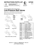
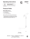
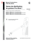
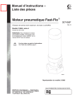
INSTRUCTIONS-PARTS LIST
308612
Rev. D
This manual contains important
warnings and information.
READ AND KEEP FOR REFERENCE.
INSTRUCTIONS
Stainless Steel, Air-Operated
Bead Spray Gun
200 psi (13.8 bar) Maximum Working Pressure
Model 238338, Series A
05949
GRACO INC.
P.O. BOX 1441
MINNEAPOLIS, MN
ECOPYRIGHT 1996, GRACO INC.
Graco Inc. is registered to I.S. EN ISO 9001
55440–1441
Table of Contents
Warnings . . . . . . . . . . . . . . . . . . . . . . . . . . . . . . . . . . . . . .
Installation . . . . . . . . . . . . . . . . . . . . . . . . . . . . . . . . . . . . .
Operation . . . . . . . . . . . . . . . . . . . . . . . . . . . . . . . . . . . . .
Maintenance . . . . . . . . . . . . . . . . . . . . . . . . . . . . . . . . . . .
Service . . . . . . . . . . . . . . . . . . . . . . . . . . . . . . . . . . . . . . .
2
4
5
7
7
Troubleshooting . . . . . . . . . . . . . . . . . . . . . . . . . . . . . . . . 8
Parts . . . . . . . . . . . . . . . . . . . . . . . . . . . . . . . . . . . . . . . . 10
Technical Data . . . . . . . . . . . . . . . . . . . . . . . . . . . . . . . . 12
Graco Phone Number . . . . . . . . . . . . . . . . . . . . . . . . . . 12
Warranty . . . . . . . . . . . . . . . . . . . . . . . . . . . . . . . . . . . . . 12
Symbols
Warning Symbol
Caution Symbol
WARNING
CAUTION
This symbol alerts you to the possibility of serious
injury or death if you do not follow the instructions.
This symbol alerts you to the possibility of damage to
or destruction of equipment if you do not follow the
instructions.
WARNING
PRESSURIZED EQUIPMENT HAZARD
Beads sprayed from the gun, leaks or ruptured components can splash in the eyes and cause serious
injury.
D Do not point the gun at anyone or at any part of the body.
D Do not put your hand or fingers over the spray tip.
D Do not stop or deflect leaks with your hand, body, glove or rag.
D Follow the Pressure Relief Procedure on page 5 if the spray tip clogs and before cleaning,
checking or servicing the equipment.
D Tighten all fluid connections before operating the equipment.
D Check the hoses, tubes, and couplings daily. Replace worn or damaged parts immediately.
2
308612
WARNING
EQUIPMENT MISUSE HAZARD
Equipment misuse can cause the equipment to rupture or malfunction and result in serious injury.
INSTRUCTIONS
D This equipment is for professional use only.
D Read all instruction manuals, tags, and labels before operating the equipment.
D Use the equipment only for its intended purpose. If you are not sure, call your distributor.
D Do not alter or modify this equipment.
D Check equipment daily. Repair or replace worn or damaged parts immediately.
D Do not exceed the maximum working pressure of the lowest rated system component. Refer to the
Technical Data on page 12 for the maximum working pressure of this equipment.
D Do not use hoses to pull equipment.
D Route hoses away from traffic areas, sharp edges, moving parts, and hot surfaces. Do not expose
Graco hoses to temperatures above 82_C (180_F) or below –40_C (–40_F).
D Do not lift pressurized equipment.
D Comply with all applicable local, state, and national fire, electrical, and safety regulations.
308612
3
Installation
NOTE: Reference numbers in parentheses in the text
refer to the numbers in the Parts.
Grounding
Accessories are available from Graco. Be sure all
accessories are properly sized to withstand the pressures in the system.
To reduce the risk of static sparking, ground the pump,
bead spray gun, paint spray gun and all other system
equipment.
Proper grounding is essential to maintaining a safe
system.
1. Pump: use a ground wire and clamp.
Mount Valve
2. Air compressors and hydraulic power supplies:
follow manufacturer’s recommendations.
Mount the valve on a 0.50 in. (12.7 mm) diameter rod
on a mounting fixture or a dispensing machine. The
bead gun has a clamping set screw (6) for mounting.
3. Air and fluid hoses connected to the pump: use
only grounded hoses with a maximum of 500 feet
(150 m) combined hose length to ensure grounding continuity.
Connect the Air Lines
4. Dispensing valve: obtain grounding through connection to a properly grounded fluid hose, frame
and pump.
5. Fluid supply container: according to local code.
Clean all lines and connections of dirt, burrs, etc. and
blow them out with clean air before connecting them to
the system. Install an air filter in the air supply line to
remove harmful dirt and moisture from the compressed
air.
4
308612
6. All solvent pails used when flushing: ground according to local code. Use only metal pails, which
are conductive. Do not place the pail on a nonconductive surface, such as paper or cardboard,
which interrupts the grounding continuity.
Operation
Pressure Relief Procedure
WARNING
FLUID INJECTION HAZARD
To reduce the risk of serious bodily injury, including fluid injection,splashing in
the eyes or on the skin, or injury from
moving parts, always follow this procedure whenever you shut off the pump, when checking or servicing any part of the dispensing system, when
installing, cleaning, or changing part of the valve,
and whenever you stop dispensing.
1. Shut off the air supply to the bead tank. Bleed the
bead tank.
2. Close the bleed-type master air valve (required
with air-powered pumps).
3. Actuate the dispensing valve to relieve pressure.
4. Leave the drain valve(s) open until you are ready
to dispense again.
If you suspect that the dispensing valve or hose is
completely clogged, or that pressure has not been fully
relieved after following the steps above, very slowly
loosen the hose end coupling and relieve pressure
gradually, then loosen completely. Now clear the valve
or hose.
Adjustments
Set the actuating air to at least 50 psi (3.5 bar) and
start the pump. Set the glass bead supply tank pressure between 30 psi and 75 psi for desired flow rate.
Note: Bead delivery will vary with each application.
Always test the system for actual delivery and adjust
air pressure or nozzle size as needed.
Application Data
See Road Lazer System Manual 308611.
Nozzle Size Selection
Use the Nozzle Size Selection and Bead Delivery
Tables to select the size of nozzle for the travel speed
and bead coverage to be used. These tables are
based on a 15 mil paint application.
1. Go to Bead Delivery (Lb/Min) Table and select:
a. Speed in MPH or KPH row.
b. Bead coverage in Pounds Per Gallon
column.
c.
Value at intersection of MPH row and Pounds
Per column is bead delivery in lb/min.
2. Go to Nozzle Size Selection Table and select:
a. Bead Delivery (lb/min) column determined by
Bead delivery (lb/min) value.
b. Psi value Glass Bead Tank psi row.
c.
Curve (1, 2, 3 or 4) at intersection of Glass
Bead Tank psi row and Bead Delivery (lb/min)
column is nozzle size value.
d. Select nozzle size that allows range of adjustment for more or less flow.
308612
5
Operation
Bead Delivery Lb/Min (kg/Min)
Speed
Bead Coverage in Pounds Per Gallon (kg/L)
MPH
KPH
4 (.48)
5 (.60)
6 (.72)
7 (.84)
8 (.96)
9 (1.08)
2
3.2
2.4 (1.09)
3.0 (1.36)
3.6 (1.63)
4.1 (1.86)
4.7 (2.13)
5.3 (2.40)
3
4.8
3.6 (1.63)
4.4 (2.0)
5.3 (2.40)
6.2 (2.81)
7.1 (3.22)
8.0 (3.62)
4
6.4
4.7 (2.13)
5.9 (2.68)
7.1 (3.22)
8.3 (3.76)
9.5 (4.31)
10.7 (4.85)
5
8
5.9 (2.68)
7.4 (3.36)
8.9 (4.04)
10.4 (4.72)
11.9 (5.40)
13.3 (6.03)
6
9.6
7.1 (3.22)
8.9 (4.04)
10.7 (4.85)
12.4 (5.62)
14.2 (6.44)
16.0 (7.26)
7
11.2
8.3 (3.76)
10.4 (4.72)
12.4 (5.62)
14.5 (6.58)
16.6 (7.53)
18.7 (8.48)
8
12.8
9.5 (4.31)
11.9 (5.40)
14.2 (6.44)
16.6 (7.53)
19.0 (8.62)
21.3 (9.66)
9
14.4
10.7 (4.85)
13.3 (6.03)
16.0 (7.26)
18.7 (8.48)
21.3 (9.66)
24.0 (10.9)
10
16
11.9 (5.40)
14.8 (6.71)
17.8 (8.07)
20.7 (9.39)
23.7 (10.8)
26.7 (12.1)
11
17.6
13.0 (5.90)
16.3 (7.39)
19.6 (8.89)
22.8 (10.3)
26.1 (11.8)
29.3 (13.3)
12
19.2
14.2 (6.44)
17.8 (8.07)
21.3 (9.66)
24.9 (11.3)
28.4 (12.9)
32.0 (14.5)
Nozzle Size Selection
(4.76) 70
1
Glass Bead Tank psi
(4.08) 60
2
3
4
5
(3.40) 50
(bar)
(2.72) 40
(2.04) 30
(1.36) 20
(0.68) 10
0
0
5
(2.27)
10
(4.54)
ORIFICE DIAMETER
1 0.203
3 0.280
2 0.234
4 0.344
5 0.420
6
308612
15
(6.80)
20
(9.07)
25
(11.3)
30
(13.6)
Bead Delivery lb/min (kg/min)
35
(15.9)
40
(18.2)
45
(20.4)
Maintenance
Clean Dispensing Valve and System Daily
Clean the outside surfaces of the valve by wiping with
a soft cloth dampened with a compatible solvent.
CAUTION
Be sure that the solvent you use is compatible with
the fluid being dispensed, to avoid clogging the
valve’s fluid passages.
An important part of the care and maintenance of your
automatic dispensing valve is proper flushing. Flush
the valve daily with a compatible solvent until all traces
of fluid are removed from the valve passages. Follow
the Pressure Relief Procedure on page 5 before
flushing.
CAUTION
Never immerse the entire dispensing valve in
solvent. Immersing in solvent removes lubricants
and tends to damage packings.
To remove a hardened particle from the orifice, blow
air through the orifice from the front.
Service
Needle, Seat and Packings
10. Install seal nut (21).
To clean or replace the needle (18), its seat (17) or
packings (19 or 15), proceed as follows:
11. Install gun needle (18).
1. Follow Pressure Relief Procedure on page 5
12. Install o-ring (19) on valve seat (2) and insert into
valve housing (4).
2. Remove retaining nut (3).
3. Remove valve housing (4).
4. Remove valve seat (2) and o-ring (19) from valve
housing (4). Remove o-ring.
13. Install retaining nut (3).
Air Piston, Spring and Seals
7. Remove o-ring (15).
Follow the Pressure Relief Procedure on page 5,
then remove the valve as explained, preceding. Remove the air cylinder cap (7), take out the spring (8)
and pull the piston (10) out. Clean and inspect all
parts. Check the piston o-rings (11, 12) carefully.
Lubricate all parts with a light waterproof grease and
reassemble the valve using new parts as necessary.
8. Clean all parts.
Repair Kit
9. Lubricate o-ring (15) with one drop of oil. Install
o-ring.
Repair Kit 238340 includes the parts listed with an * in
Parts on page 11.
5. Remove gun needle (18).
6. Remove seal nut (21).
308612
7
Troubleshooting
NOTE: Check all possible solutions before disassembling the pump.
Cause
Problem
Solution
Uneven spray pattern
Bead pressure too low
Increase pressure to bead tank, or
adjust bead pressure regulator
Spray gun will not stop spraying
Gun needle binding
Clean, repair
Obstructed or worn needle seat
Clean or replace
Bead line clogged
Clear
Bead valve closed
Open
Clogged orifice or needle seat
Clean
No trigger or actuator air pressure
Check, clean air lines
Wet beads
Drain beads from tank and replace
with dry beads.
Spray gun will not spray
8
308612
Notes
308612
9
Parts
7
Model 238338
8
9
11*
10
12*
13*
6
14
5
4
15*
16
21*
17
18*
19**
2**
20
3
1
05950A
10
308612
Parts
Model 238338
Ref.
No.
1
2
3
4
5
6
7
8
9
10
11
12
13
14
15
16
17
18
19
20
21
Part No.
Description
238330
191201**
191196
191206
166847
101554
191197
164739
164740
164741
156593*
155685*
191195*
102300
158486*
DEFLECTOR
SEAT, valve
NUT, retaining
HOUSING, valve
HOUSING, valve
SET SCREW, 3/8–16 x 3/4 in.
CAP, air cylinder
SPRING, helical compression
GUIDE, spring
PISTON, air
O-RING; nitrile rubber
PACKING, O-ring
TUBE, protection
NUT, jam, 7/8 in. hex; 9/16–18 nf
PACKING,O-ring
NUT, packing
SEAT, needle
NEEDLE, gun
O-RING
RING, retaining, external
NUT, seal (Includes 16 and 17)
191192*
166702**
113463
238341*
Qty.
* Included in Repair Kit 238340. Order separately.
** The Road Lazer ships with the three Valve Seat &
O-ring Kits listed in the following table:
1
1
1
1
1
1
1
1
1
1
1
1
1
1
1
1
1
1
1
1
1
Ref.
No.
Part No.
Description
Qty.
Valve Seat & O-ring Kits
Valve Seat
Nozzle Size
Kit
(Includes O-ring)
0.203
238663
0.234
238666
0.281
238664
0.334
238665
0.420†
243668
† Nozzle size 0.420 is optional; order separately
Accessories
Wide Bead Deflector Kit
239695
Allows application of 12 in. wide beaded lines.
308612
11
Technical Data
Maximum working pressure . . . . . . . . . 200 psi (12 bar)
Operating pressure of air actuated trigger
Minimum . . . . . . . . . . . . . . . . . . . . . . . . 50 psi (3 bar)
Maximum . . . . . . . . . . . . . . . . . . . . . . 200 psi (12 bar)
Air connection . . . . . . . . . . . . . . . . . . . 1/4 npt(f) air inlet
Bead connection . . . . . . . . . . . . . . . 3/4 npt(f) bead inlet
Glass bead output . . . . 2 to 40 lb/min (.9 to 18 kg/min)
Air consumption . . . . . . . . . . . . . . . . . . . . . . . . 2 to 7 cfm
Spray width . . . . . . . . . . . . . . . 2 to 12 in (50 to 304 mm)
Graco Phone
Number
TO PLACE AN ORDER, contact your Graco distributor, or call this number to identify the distributor
closest to you: 1–800–690–2894 Toll Free
Graco Warranty
Graco warrants all equipment manufactured by Graco and bearing its name to be free from defects in material and workmanship on the
date of sale by an authorized Graco distributor to the original purchaser for use. With the exception of any special, extended, or limited
warranty published by Graco, Graco will, for a period of twelve months from the date of sale, repair or replace any part of the equipment
determined by Graco to be defective. This warranty applies only when the equipment is installed, operated and maintained in accordance with Graco’s written recommendations.
This warranty does not cover, and Graco shall not be liable for general wear and tear, or any malfunction, damage or wear caused by
faulty installation, misapplication, abrasion, corrosion, inadequate or improper maintenance, negligence, accident, tampering, or substitution of non–Graco component parts. Nor shall Graco be liable for malfunction, damage or wear caused by the incompatibility of
Graco equipment with structures, accessories, equipment or materials not supplied by Graco, or the improper design, manufacture,
installation, operation or maintenance of structures, accessories, equipment or materials not supplied by Graco.
This warranty is conditioned upon the prepaid return of the equipment claimed to be defective to an authorized Graco distributor for
verification of the claimed defect. If the claimed defect is verified, Graco will repair or replace free of charge any defective parts. The
equipment will be returned to the original purchaser transportation prepaid. If inspection of the equipment does not disclose any defect
in material or workmanship, repairs will be made at a reasonable charge, which charges may include the costs of parts, labor, and
transportation.
THIS WARRANTY IS EXCLUSIVE, AND IS IN LIEU OF ANY OTHER WARRANTIES, EXPRESS OR IMPLIED, INCLUDING BUT
NOT LIMITED TO WARRANTY OF MERCHANTABILITY OR WARRANTY OF FITNESS FOR A PARTICULAR PURPOSE.
Graco’s sole obligation and buyer’s sole remedy for any breach of warranty shall be as set forth above. The buyer agrees that no other
remedy (including, but not limited to, incidental or consequential damages for lost profits, lost sales, injury to person or property, or any
other incidental or consequential loss) shall be available. Any action for breach of warranty must be brought within two (2) years of the
date of sale.
Graco makes no warranty, and disclaims all implied warranties of merchantability and fitness for a particular purpose in connection
with accessories, equipment, materials or components sold but not manufactured by Graco. These items sold, but not manufactured
by Graco (such as electric motors, switches, hose, etc.), are subject to the warranty, if any, of their manufacturer. Graco will provide
purchaser with reasonable assistance in making any claim for breach of these warranties.
In no event will Graco be liable for indirect, incidental, special or consequential damages resulting from Graco supplying equipment
hereunder, or the furnishing, performance, or use of any products or other goods sold hereto, whether due to a breach of contract,
breach of warranty, the negligence of Graco, or otherwise.
FOR GRACO CANADA CUSTOMERS
The parties acknowledge that they have required that the present document, as well as all documents, notices and legal proceedings
entered into, given or instituted pursuant hereto or relating directly or indirectly hereto, be drawn up in English. Les parties reconnaissent avoir convenu que la rédaction du présente document sera en Anglais, ainsi que tous documents, avis et procédures judiciaires
exécutés, donnés ou intentés à la suite de ou en rapport, directement ou indirectement, avec les procedures concernées.
ADDITIONAL WARRANTY COVERAGE
Graco does provide extended warranty and wear warranty for products described in the “Graco Contractor Equipment Warranty
Program”.
All written and visual data contained in this document reflects the latest product information available at the time of publication.
Graco reserves the right to make changes at any time without notice.
Sales Offices: Atlanta, Chicago, Detroit
Foreign Offices: Belgium, Korea, Hong Kong, Japan
GRACO INC.
P.O. BOX 1441
MINNEAPOLIS, MN
http://www.graco.com
PRINTED IN U.S.A. 308612 March 1996, Revised 02/2000
12
308612
55440–1441