1
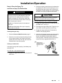
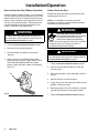
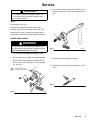
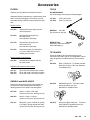
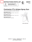
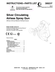
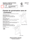
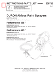
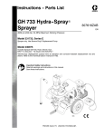
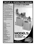
INSTRUCTIONS-PARTS LIST
308–235
Rev. F
Supersedes Rev. E
This manual contains important
warnings and information.
READ AND KEEP FOR REFERENCE.
INSTRUCTIONS
Flex Airless Spray Gun
5000 psi (345 bar) MAXIMUM WORKING PRESSURE
Model 235–457, Series C
Bare gun.
Model 237–691, Series B
Includes RAC IV DripLess Tip Guard, 517 size
SwitchTip, and 2 finger trigger.
Model 235–459, Series D
Includes RAC IV DripLess Tip Guard, 517 size
SwitchTip, and 2 finger trigger.
Model 235–459
Model 235–458, Series C
Includes the Standard (non-reversing) DripLess
Tip Guard. Spray tip not included; order separately.
01460
Patents Pending
Model 235–458
GRACO INC.
P.O. BOX 1441 MINNEAPOLIS, MN
COPYRIGHT 1992, GRACO INC.
Graco Inc. is registered to I.S. EN ISO 9001
55440–1441
Table of Contents
Warnings . . . . . . . . . . . . . . . . . . . . . . . . . . . . . . . . . . . . . . 2
Installation/Operation . . . . . . . . . . . . . . . . . . . . . . . . . . . 4
Pressure Relief Procedure . . . . . . . . . . . . . . . . . . . 5
System Requirements . . . . . . . . . . . . . . . . . . . . . . . 5
How to Use the Gun Trigger Safety . . . . . . . . . . . 5
How to Use the Gun . . . . . . . . . . . . . . . . . . . . . . . . 6
How to Adjust the Spray Pattern . . . . . . . . . . . . . . 6
How to Clean the Spray Tip
and Clear a Spray Tip Obstruction . . . . . . . . . . . . 7
How to Check the Gun Diffuser . . . . . . . . . . . . . . . . 8
How to Clean the Filter . . . . . . . . . . . . . . . . . . . . . . . . 6
How to Flush the Gun . . . . . . . . . . . . . . . . . . . . . . . . . 8
Service . . . . . . . . . . . . . . . . . . . . . . . . . . . . . . . . . . . . . . . 9
Parts Drawing . . . . . . . . . . . . . . . . . . . . . . . . . . . . . . . . 11
Technical Data . . . . . . . . . . . . . . . . . . . . . . . . . . . . . . . 14
Graco Phone Numbers . . . . . . . . . . . . . . . . . . . . . . . . . 14
Warranty . . . . . . . . . . . . . . . . . . . . . . . . . . . . . . . . . . . . . 16
Symbols
Warning Symbol
WARNING
This symbol alerts you to the possibility of serious
injury or death if you do not follow the instructions.
Caution Symbol
CAUTION
This symbol alerts you to the possibility of damage to
or destruction of equipment if you do not follow the
instructions.
WARNING
EQUIPMENT MISUSE HAZARD
Equipment misuse can cause the equipment to rupture or malfunction and result in serious injury.
INSTRUCTIONS
This equipment is for professional use only.
Read all instruction manuals, tags, and labels before operating the equipment.
Use the equipment only for its intended purpose. If you are not sure, call your Graco distributor.
Do not alter or modify this equipment.
Check equipment daily. Repair or replace worn or damaged parts immediately.
Do not exceed the maximum working pressure of the lowest rated system component. Refer to the
Technical Data on page 14 for the maximum working pressure of this equipment.
Use fluids and solvents which are compatible with the equipment wetted parts. Refer to the Technical Data section of all equipment manuals. Read the fluid and solvent manufacturer’s warnings.
Do not use 1,1,1–trichloroethane, methylene chloride, other halogenated hydrocarbon solvents or
fluids containing such solvents in pressurized aluminum equipment. Such use could result in a
chemical reaction, with the possibility of explosion.
Do not use hoses to pull equipment.
Route hoses away from traffic areas, sharp edges, moving parts, and hot surfaces. Do not expose
Graco hoses to temperatures above 66C (150F) or below –40C (–40F).
Wear hearing protection when operating this equipment.
Do not lift pressurized equipment.
Comply with all applicable local, state, and national fire, electrical, and safety regulations.
WARNING
INJECTION HAZARD
Spray from the gun, leaks or ruptured components can inject fluid into your body and cause extremely
serious injury, including the need for amputation. Fluid splashed in the eyes or on the skin can also
cause serious injury.
Fluid injected into the skin might look like just a cut, but it is a serious injury. Get immediate medical attention.
Do not point the gun at anyone or at any part of the body.
Do not put your hand or fingers over the spray tip.
Do not stop or deflect leaks with your hand, body, glove or rag.
Do not “blow back” fluid; this is not an air spray system.
Always have the tip guard and the trigger guard on the gun when spraying.
Check the gun diffuser operation weekly. See page 8.
Be sure the gun trigger safety operates before spraying.
Lock the gun trigger safety when you stop spraying.
Follow the Pressure Relief Procedure on page 5 if the spray tip clogs and before cleaning,
checking or servicing the equipment.
Tighten all fluid connections before operating the equipment.
Check the hoses, tubes, and couplings daily. Replace worn or damaged parts immediately.
Do not repair high pressure couplings; you must replace the entire hose.
Fluid hoses must have spring guards on both ends, to help protect them from rupture caused by
kinks or bends near the couplings.
MOVING PARTS HAZARD
Moving parts can pinch or amputate your fingers.
Keep clear of all moving parts when starting or operating the pump.
Before servicing the equipment, follow the Pressure Relief Procedure on page 5 to prevent the
equipment from starting unexpectedly.
RECOIL HAZARD
Due to the high pressure fluid emitted, a strong recoil action may occur when you trigger this gun. If
you are unprepared, your hand could be forced back toward your body or you could lose your balance
and fall, resulting in serious injury.
WARNING
FIRE AND EXPLOSION HAZARD
Improper grounding, poor ventilation, open flames or sparks can cause a hazardous condition and
result in a fire or explosion and serious injury.
If there is any static sparking or you feel an electric shock while using this equipment, stop spraying immediately. Do not use the equipment until you identify and correct the problem.
Provide fresh air ventilation to avoid the buildup of flammable fumes from solvents or the fluid
being sprayed.
Keep the spray area free of debris, including solvent, rags, and gasoline.
Electrically disconnect all equipment in the spray area.
Extinguish all open flames or pilot lights in the spray area.
Do not smoke in the spray area.
Do not turn on or off any light switch in the spray area while operating or if fumes are present.
Do not operate a gasoline engine in the spray area.
Ground the equipment and the object being sprayed. Refer to your pump instruction manual.
TOXIC FLUID HAZARD
Hazardous fluid or toxic fumes can cause serious injury or death if splashed in the eyes or on the skin,
inhaled, or swallowed.
Know the specific hazards of the fluid you are using.
Store hazardous fluid in an approved container. Dispose of hazardous fluid according to all local,
state and national guidelines.
Always wear protective eyewear, gloves, clothing and respirator as recommended by the fluid and
solvent manufacturer.
4
308-235
Installation/Operation
Pressure Relief Procedure
WARNING
INJECTION HAZARD
The system pressure must be manually
relieved to prevent the system from
starting or spraying accidentally. Fluid
under high pressure can be injected through the
skin and cause serious injury. To reduce the risk of
an injury from injection, splashing fluid, or moving
parts, follow the Pressure Relief Procedure
whenever you:
are instructed to relieve the pressure,
stop spraying,
check or service any of the system equipment,
or install or clean the spray tips.
1. Lock the gun trigger safety.
2. Shut off the power supply to the pump. Close any
bleed-type master air valves.
3. Unlock the gun trigger safety.
4. Hold a metal part of the gun firmly to the side of a
grounded metal pail, and trigger the gun to relieve
pressure.
5. Lock the gun trigger safety.
6. Open the drain valve (required in your system),
having a container ready to catch the drainage.
7. Leave the drain valve open until you are ready to
spray again.
WARNING
Be sure your system has a bleed-type master air
valve (pneumatic pumps only) and a pressure drain
valve. These accessories help reduce the risk of
serious bodily injury, including fluid injection,
splashing in the eyes or on the skin, or injury from
moving parts, if you are adjusting or repairing the
pump or gun.
1. The bleed-type master air valve (air-powered
pumps only) relieves air trapped between this
valve and the pump after the air regulator is shut
off. Trapped air can cause the pump to cycle
unexpectedly.
2. The pressure drain valve assists in relieving fluid
pressure in the displacement pump, hose and gun:
triggering the gun to relieve pressure may not be
sufficient.
3. Strain the fluid you are spraying if it contains
particles which could clog the spray tip.
How to Use the Gun Trigger Safety
1. To lock the gun trigger safety, turn the latch (A) to
a right angle with the gun body. See Fig. 1.
2. To unlock the gun trigger safety, push the latch (A)
out and turn it parallel with the gun body.
If you suspect that the spray tip or hose is completely
clogged, or that pressure has not been fully relieved
after following the steps above, very slowly loosen the
tip guard retaining nut or hose end coupling and relieve
pressure gradually, then loosen completely. Now clear
the tip or hose.
LOCKED
System Requirements
WARNING
Keep the wallet-sized warning card provided with
this gun with the operator at all times. The card
contains important treatment information should an
injection injury occur. Additional cards are available
at no charge from Graco Inc.
UNLOCKED
01464
Fig. 1
Installation/Operation
How to Use the Gun
1. Guide a grounded fluid hose (with spring guard)
through the hose guard (14) and connect the hose
to the gun inlet. See Fig. 2.
2. With no tip installed, start the pump. Flush the
pump according to the instructions supplied with it.
Prime the system with the fluid.
WARNING
To reduce the risk of serious injury whenever you
are instructed to relieve pressure, always follow the
Pressure Relief Procedure on page 5.
3. Relieve the pressure. Be sure the gun trigger
safety is locked. See Fig. 1.
4. Model 235–459: Unscrew the tip guard (1) and
install the tip (A) and the gasket (2d) in the nut of
the tip guard. Screw the assembly firmly onto the
gun. Tighten the assembly with a wrench. See
Fig. 2.
7. If adjusting the pressure does not give a good
spray pattern, follow the Pressure Relief Procedure on page 5 and then try another tip size.
8. Use a full-open, full-close triggering action. Hold
the gun about 14 in. (350 mm) from and at right
angles to the work surface. Don’t swing the gun in
an arc. Practice to find the best length and speed
of stroke.
How to Adjust the Spray Pattern.
1. To adjust the spray pattern direction, follow the
Pressure Relief Procedure on page 5. Loosen
the tip guard retaining nut (B). Turn the tip guard/
tip groove horizontally (C) for a horizontal pattern
and vertically (A) for a vertical pattern. Tighten the
retaining nut.
2. The spray tip orifice and spray angle determines
the coverage and size of the pattern. When more
coverage is needed, use a larger spray tip rather
than increasing the fluid pressure.
NOTE: If the gasket (2d) is not installed, the gun
will leak.
5. Models 235–459 and 237–691: install the
SwitchTip (19) and the tip guard (18). See manual
308–644, supplied.
1
A
CAUTION
The openings in the tip guard reduce paint buildup on
the tip guard while spraying. Any damage to the
sharp edges of the openings causes paint to collect
at that area. Never hang the gun by the tip guard.
2d
KEY
A
Tip guard shown in position for
vertical spray pattern
B
Retaining nut
C
Tip guard shown in position for
horizontal spray pattern
B
19
18
A
14
01463
Fig. 2
6. Start the pump. Adjust the fluid pressure until the
spray is completely atomized. Use the lowest
pressure necessary to get the desired results.
Higher pressure may not improve the spray pattern
and will cause premature tip wear and pump wear.
Fig. 3
C
Installation/Operation
How to Clean the Spray Tip
and Clear a Spray Tip Obstruction.
WARNING
2. Remove the spray tip and blow out the obstruction
by applying air to the front of the spray tip. Or, let
the spray tip and gun nozzle soak to dissolve the
obstruction. If it won’t dissolve, jar it out by tapping
the back of the spray tip against a flat surface.
To reduce the risk of fluid injection or splashing in
the eyes or on the skin, do not hold a hand, body
or rag in front of the spray tip when cleaning or
checking a clogged tip. Point the gun toward the
ground or into a waste container when checking to
see if the spray tip is cleared.
Gun 235–459 and 237–691– with RAC IV tip guard
Do not try to “blow back” paint; this is not an air
spray gun.
1. Engage the trigger safety latch. Rotate the RAC IV
tip handle 180. See Fig. 4.
Do not wipe fluid buildup off the gun or spray tip
until pressure is relieved.
2. Disengage the trigger safety latch. Trigger the gun
into a pail or onto the ground to remove clog.
Cleaning during the day.
1. Follow the Pressure Relief Procedure, page 5.
2. Clean the front of the tip frequently during the day
to help reduce buildup. Also clean the tip and tip
guard at the end of each work day. Use a solventsoaked brush to clean the spray tip.
Clearing an obstruction.
If the spray tip clogs while spraying, immediately stop
spraying, then:
CAUTION
Never soak the entire gun in solvent. Prolonged
exposure to solvent can ruin the packings.
3. Engage the trigger safety latch. Rotate the tip
handle to the spraying position.
4. If the tip is still clogged, lock the gun trigger safety,
shut off the sprayer and disconnect the power
source, and open the pressure drain valve to
relieve pressure. Clean the spray tip as shown in
manual 308–644, supplied with the RAC IV.
KEY
A
Handle shown in
spraying position. Turn
handle 180 and
trigger gun to clear
clog.
Gun 235–458 – with standard tip guard
1. Engage the trigger safety latch, open the pressure
drain valve.
A
Fig. 4
Installation/Operation
How to Check the Gun Diffuser Operation
How to Flush the Gun.
Check the diffuser operation weekly. The gun diffuser/
seat (2a) breaks up spray and reduces the risk of fluid
injection when the tip is not installed. Perform the test
below. If it fails, replace the entire Needle Kit, Part No.
235–474, as instructed on page 7. Diffuser/seats are
not sold separately since the gun will leak if an old
needle is used with a new diffuser/seat.
Always flush the pump and the gun before the fluid
being sprayed can dry in it.
WARNING
To reduce the risk of serious injury whenever you
are instructed to relieve pressure, always follow the
Pressure Relief Procedure on page 5.
1. Follow the Pressure Relief Procedure, page 5.
2. Remove the tip guard and spray tip.
3. Start the sprayer and adjust it to the lowest
pressure.
4. Aim the gun into a grounded metal pail while
holding it firmly to the pail. Trigger the gun. If the
fluid emitted is not diffused into an irregular
stream, replace the entire needle kit immediately.
See Fig. 5.
2a
NOTE: If it is available, the flushing procedure
provided in your pump or sprayer manual should be
used instead of this procedure.
WARNING
FIRE AND EXPLOSION HAZARD
Static sparking and splashing may cause
fire, explosion and serious injury. To
reduce static sparking and splashing,
always remove the spray tip from the gun, and hold
a metal part of the gun firmly to the side of a
grounded metal pail when flushing.
WARNING
To reduce the risk of serious injury whenever you
are instructed to relieve pressure, always follow the
Pressure Relief Procedure on page 5.
1. Follow the Pressure Relief Procedure, page 5.
2. Remove the tip guard and spray tip. Soak and
clean the parts.
3. Put the pump intake in a grounded pail of water or
solvent.
4. Start the pump at its lowest pressure.
5. Trigger the gun into the original pail. When solvent
appears, release the trigger.
6. Now trigger the gun into the solvent pail. Circulate
the fluid until the system is thoroughly flushed.
Fig. 5
7. Follow the Pressure Relief Procedure, page 5.
Service
CAUTION
Do not attempt to install an old style needle in this
gun. The front of the new needle is marked with a +
below the Graco symbol.
4. Insert a punch into the rear of the gun and tap it to
push the needle (2c*) out the front of the gun. See
Fig. 7.
Notes:
Use Needle Kit 235–474.
Use all the new parts for the best results. Parts
included in the kit are shown with one asterisk, (2a*).
Keep parts very clean. Dried paint or other contaminants cause friction which causes parts to wear faster.
2c
Needle Replacement.
WARNING
To reduce the risk of serious injury whenever you
are instructed to relieve pressure, always follow the
Pressure Relief Procedure on page 5.
Fig. 7
02350
1. Follow the Pressure Relief Procedure, page 5.
2. Remove the hose, tip guard, spray tip and gasket.
3. Remove the diffuser/seat (2a*) and gasket (2b*).
Remove the screw (12), pivot pin (11), and trigger
(8). See Fig. 6.
Lubricate, then torque
to 20–25 ft–lb (27–34 N.m)
2a*
2b*
11
5. Clean the internal passages of the gun.
6. Grease the rings (A) of the new needle (2c*). See
Fig. 8.
A
8
12
Fig. 8
Fig. 6
02349
Service
7. Slide the rear of the needle (2c*) into the front of
the gun. Slide the tool (B), provided with the repair
kit, into the gun, around the needle. Lightly tap the
tool with a hammer or lightly press the tool against
a flat surface to seat the needle. See Fig. 9.
Remove the tool.
CAUTION
B
2c
10
02351
308-235
9. Grease the diffuser/seat threads. Place the new
gasket (2b*) on the diffuser/seat (2a*) and screw
the assembly into the fluid housing (7). Torque to
20–25 ft-lb (27–34 N.m). See Fig. 6.
10. Install the trigger (8), pivot pin (11) and screw (12).
See Fig. 6.
Tapping or pressing the tool too hard may jam the
tool and damage the needle.
Fig. 9
8. Grease the end of the needle.
NOTE: No needle or trigger adjustment is needed.
Parts
11
3
6
2
4
2d*
1
8
13
2
2b*
1
7
12
9
2c*
14
2a*
15
1
19
Lubricate, then
torque to 20-25 ft-lb
(27-34 N.m)
2
Lubricate
3
Torque to 30-40 in-lb
(3.4–4.5 N.m)
4
Purchase separately
18
01468
Model 235–459, Series D
Model 237–691, Series B
ncludes RACr IV DripLesst Tip Guard.
Includes items 2 to 19 as indicated by model number.
Model 235–457, Series C
Includes the Standard (non-reversing) DripLesst
Tip Guard.
Includes items 2 (not 2d) to 17 as indicated by model
number.
Model 235–458, Series C
Includes the Standard (non-reversing) DripLesst
Tip Guard.
Includes items 1 to 17 as indicated by model number.
Ref
No.
Part No.
Description
1
220–222
STANDARD TIP GUARD
2
235–474
2a*
2b*
2c*
2d*
Z
Z
Z
166–969
Qty.
Model 235–458 only
1
Includes items 2a to 2d
1
1
1
1
NEEDLE KIT
DIFFUSER/SEAT
GASKET, copper
NEEDLE
TIP GASKET
Use in gun model 235–458 only
1
Ref
No.
Part No.
Description
6
7
8
9
11
12
13
14
15
16Y
169–797
187–972
187–985
102–207
187–965
203–953
235–470
218–139
107–257
187–987
ADAPTER
FLUID HOUSING
TRIGGER
SETSCREW, 1/4–20
PIVOT PIN
SCREW, hex washer hd, 10–24
GUN HANDLE
HOSE HOLDER
CAPSCREW, 1/4–20 x 1/2”
WARNING TAG not shown
Y
187–346
WARNING SHEET not shown
17Y
18
222–385
220–422
19
221–517
Qty.
1
1
1
1
1
1
1
1
1
Model 235–458 only
1
Model 235–459 only
1
1
Model 235–459 only
1
Model 235–459 only
1
WARNING CARD not shown
RAC IV DripLess TIP GUARD
SwitchTip, Size 517
* These parts are also included in Repair Kit
235–474, which may be purchased separately. Kit
also includes installation tool.
Z Part not sold separately.
Y Replacement Danger and Warning labels, tags,
and cards are available at no cost.
308-235
11
Notes
12
308-235
Accessories
FILTERS
TOOLS
3000 psi (210 bar) Maximum Working Pressure.
NYLON BRUSHES
Use to thoroughly clean the gun’s fluid passages.
Adequate filtering is important for a good surface finish
and to minimize tip clogging. These filters provide
secondary filtering. Various screen meshes are available.
101–891
101–892
0.375” (9 mm) dia.
0.625” (16 mm) dia.
Mounts in hose
213–068
Includes filter body, spring and one
100 mesh screen.
213–069
Includes filter spring and one
60 mesh screen.
Use with above filter body.
210–742
Includes filter spring and one
100 mesh screen.
Use with above filter body.
NEEDLE TOOL
188–369
Required to install new needle
without damaging it.
210–729
Includes assembly 213–068 plus a
3 ft (0.9 m) whip hose for more
flexible gun movement.
TIP GUARDS
Mounts between hose and gun
210–500
Includes swivel, adapter and one
60 mesh screen
WRENCH
171–147
Fits all hexes on the gun.
These tip guards fit all Graco airless spray guns.
Choose the one that’s right for your application. One of
these tip guards is included with every Graco airless
gun.
220–422
RAC® IV DripLess Tip Guard. Includes
SwitchTip of choice. See your distributor
for available sizes.
220–222
Standard DripLess Tip Guard. Order
flat tip separately. See your
distributor for available sizes.
222–674
Heavy Duty RAC® DripLess Tip Guard.
Order SwitchTip separately. See your
distributor for available sizes.
Replacement screens for above filters
210–731
210–732
210–733
Three 60 mesh (250 micron) screens
Three 100 mesh (149 micron) screens
Three 200 mesh (74 micron) screens
SWIVELS and WHIP HOSES
Swivels and whip hoses provide more flexible gun
movement for easier handling and less fatigue.
Working pressures are listed in the descriptions.
207–946
204–940
214–701
Swivel, 1/2 npsm x 3/8 npt(f)
5000 psi (350 bar) Max. Working Pressure
Swivel, 1/4 npt x 1/4 npsm
3000 psi (210 bar) Max. Working Pressure
Whip hose, nylon, coupled 1/4 npsm(f)
x 3/8 npt(m), spring guards both ends.
3000 psi (210 bar) Max. Working Pressure
308-235
13
Technical Data
Maximum Working Pressure . . . . . . 5000 psi (350 bar)
Fluid Orifice Size . . . . . . . . . . . . . . . . . 0.090 in. (2.3 mm
Wetted Parts . . . . . . . . . Stainless steel, Polyethylene,
Polyurethane, Nylon, PTFE Weight . . . . . . . . . . . . . . . . . . . . . . . . . . . . . 18 oz. (510 g)
Inlet . . . . . . . . . . . . . . . . . . . . . . . . . . . . . . . . 1/4 npsm(m)
Maximum material temperature . . . . . . . 120F (50C)
Sound Data
Sound Pressure Level . . . . . . . . . . . . . . . . . 78 dB(A)*
Sound Power Level . . . . . . . . . . . . . . . . . . . 87 dB(A)*
* Measured while spraying waterbase paint – gravity
1.36 through a 517 tip at 3,000 psi (207 bar).
Per ISO 3744
PTFE is a registered trademark of the DuPont
Company.
14
308-235
Graco Phone
Number
TO PLACE AN ORDER, contact your Graco distributor, or call this number to identify the distributor
closest to you: 1–800–328–0211 Toll Free.
Manual Change Summary
Changed: Model 237–691, Series C
To: Model 237–691, Series B
308-235
15
The Graco Warranty and Disclaimers
WARRANTY
Graco warrants all equipment manufactured by it and bearing its name to be free from defects in material and workmanship on
the date of sale by an authorized Graco distributor to the original purchaser for use. As purchaser’s sole remedy for breach of this
warranty, Graco will, for a period of twelve months from the date of sale, repair or replace any part of the equipment proven defective. This warranty applies only when the equipment is installed, operated and maintained in accordance with Graco’s written recommendations.
This warranty does not cover, and Graco shall not be liable for, any malfunction, damage or wear caused by faulty installation,
misapplication, abrasion, corrosion, inadequate or improper maintenance, negligence, accident, tampering, or substitution of
non–Graco component parts. Nor shall Graco be liable for malfunction, damage or wear caused by the incompatibility with Graco
equipment of structures, accessories, equipment or materials not supplied by Graco, or the improper design, manufacture, installation, operation or maintenance of structures, accessories, equipment or materials not supplied by Graco.
This warranty is conditioned upon the prepaid return of the equipment claimed to be defective to an authorized Graco distributor
for verification of the claim. If the claimed defect is verified, Graco will repair or replace free of charge any defective parts. The
equipment will be returned to the original purchaser transportation prepaid. If inspection of the equipment does not disclose any
defect in material or workmanship, repairs will be made at a reasonable charge, which charges may include the costs of parts,
labor and transportation.
DISCLAIMERS AND LIMITATIONS
The terms of this warranty constitute purchaser’s sole and exclusive remedy and are in lieu of any other warranties (express or
implied), including warranty of merchantability or warranty of fitness for a particular purpose, and of any non–contractual
liabilities, including product liabilities, based on negligence or strict liability. Every form of liability for direct, special or consequential damages or loss is expressly excluded and denied. In no case shall Graco’s liability exceed the amount of the purchase price.
Any action for breach of warranty must be brought within two (2) years of the date of sale.
EQUIPMENT NOT COVERED BY GRACO WARRANTY
Graco makes no warranty, and disclaims all implied warranties of merchantability and fitness for a particular purpose, with
respect to accessories, equipment, materials, or components sold but not manufactured by Graco. These items sold, but not
manufactured by Graco (such as electric motor, switches, hose, etc.) are subject to the warranty, if any, of their manufacturer.
Graco will provide purchaser with reasonable assistance in making any claim for breach of these warranties.
All written and visual data contained in this document reflects the latest product information available at the time of publication.
Graco reserves the right to make changes at any time without notice.
Sales Offices: Atlanta, Chicago, Detroit, Los Angeles
Foreign Offices: Belgium, Canada, England, Korea, Switzerland, France, Germany, Hong Kong, Japan
GRACO INC.
16
308-235
P.O. BOX 1441 MINNEAPOLIS, MN
55440–1441
PRINTED IN U.S.A. 308–235 December 1992, Revised February 1998