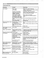
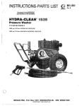
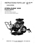
1
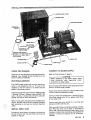
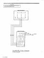
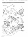
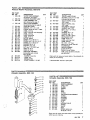
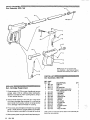
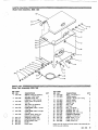
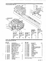
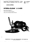
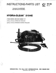
.
I
This manual contains IRAPORTA,MB
WARMLNES and lMSTWUCPlQMS
READ AND'RETAIM FOR REFERENCE
P/N 800-076 SERIES B
2500 p s i ( 1 72 bar) OPERATING PRESSURE
3400 p s i (234 bar) MAXIMUM WORKING PRESSURE
OMJECTOGPN E-iaARD
Fluids under high pressure from spray or leaks can
penetratetheskinandcauseextremelyserious
injury, including the need for amputation.
NEVER point the spray gun at anyone or any part of
the body.
Beforeeach use, checkhose for weak, worn or
damaged conditions caused by traffic, sharp
corners,
pinchingorkinking.Tightenallfluidconnections
'securelybeforeeach
use. Replace any damaged
hose.
Do notusechemicalsoragentswhicharenot
compatible with Buna-N.Viton, PVC, or neoprene
cover of hose.
NEVER put hand or fingers over the spray tip.
NEVER try to Stop or deflect leaks with your hand or
Do not leave a pressurizedunit unattended. Shut off
the unit and relieve pressure before leaving.
body.
MEDlCAL ~ R E A ~ ~ E ~ T
FURE
If anfluid
ears
a
to
enetrate
your
skin,
get
E&Effi:QG&Y
MEDU8AWa. CARE AB ONCG.
DO NOT PREAU AS A SUMRE CMU.
Tell the doctor exactly what fluid was injected.
treatmentinstructionshaveourdoctorcallthe
Do not spray flammable liquids.
unit wherecombustiblefumes
present.
For
~ RUPTURE~
Even after you shut off the electric motor, there is
high pressure in the pump, hose and gun until you
relieve it by triggering the gun. So before removing
the spray tip or servicing the unit,always shut off the
unit and trigger the gun to release pressure.
not operate the
or dust maybe
GENERAL
~ A ~ U POISON
O ~ A CdUEBa
~
NETWORK
(412) 689-6669
AVOOD C
Do
~
NEVER run the unit with the belt guard removed.
~
~
Keep clearO of moving parts
when the~ unit is running.
O b s e r vdee t e r g e n tm
- a n u f a c t u r e r 'ssa f e t y
precautions. Avoid getting detergent or other liquids
in your eyes. Follow the directions on the container
regarding
contact
with eyes.
nose,
and
.skin,
breathing fumes, etc. Always wear full goggles to
protect your eyes from the spray as
as any
well debris
Be sure
that
all
accessory items
and
system
dislodged by the 'spray. If necessary, wear gloves or
components will withstand the pressuredeveloped,
other protective clothing. If. antidotes or treatment
NEVER exceed the pressure rating of any component are recommended, be prepared to use them.
in system. NEVER alter or modify equipment-your
Don't spray toxic chemicals such as insecticide or
personal safety, as well as thefunction of 'the
weed killer.
equipment, is at stake.
2 - 801-765
~
INSTALLATION
CHECK FOR DAMAGE
CONNECT TO WATER SUPPLY
Check unit for any damage that may have occurred
in
shipping. Any damageshouldbenotedandthe
carrier notified immediately.
Refer to Parts Drawing on page 9.
ELECTRICAL SERVICE
The 1020E model comeswith an electric starter box
unit. It is up to the
which isnotattachedtothe
installer to wire the motor to the starter and the
starter to the powersource.
1020E is 230V
The electrical service required for the
/ 6Ocycle / 50Amp / 3 phase. A n optional 460V/ 60
cycle / 25 Amp / 3 phase service may be usedwith
special instructions from manufacturer.
..- ...*.
ii,
..
'
:'>,
,..
.,..
, .. 'i
connection to water supply.
Do not exceed16O0F(7O0C)watertemperaturetothe
pump in a direct supply system.
Attach lidto tank by drilling four holes
in tank and use
screws, bolts and washers provided.
Connectahosewithatleast3/4in.(ISmm)l.D.frOm
your water supply to the 3/4 in. garden hose fitting
on the water tank.
Refer to instrucfion manual for the wiring diagram on
Connect tank and pump with 3 / 4 in. I.D. hose and
page 4. Be sure that all wiring is properly grounded
clamps provided with the unit.
andaccordingtoalllocalandnationalelectrical
codes.
Place one endof hose on hose barbbottom
at
of water
tank. Place the other end of hose on hose barb at
INSTALL SPRAY G U N
pump inlet. Clamp each end with,hose clamp. Pump
be asclose togetheras
Connect the spray hose to the spray gun by inserting module and water tankshould
possible. A maximum distance of 5 ft. is recommthe pin fitting at the end of the hose into the quick
mended.
coupler on the gun.
801-765
3
WIRING DIAGRAM
CAUTION
Unit mustbe properlywired to230V/ 60cycle /
50 Amp (three phase) current.
MOTOR JUNCTION BOX
I
I
If theoptional 460V / 60 cycle / 25 Amp (three
phase) current is desired, contact the manufacturer
for further instructions.
4
801-765
ARE
OPERATION
AND
SHUTDOWN
STARTUP
OF UNIT
Before'starting, be sure to read the safety warnings
and installation instructions.
When the unit is not
in use, turn off.the watersupply.
When shutting down for theorday
weekend,shut off
the unit, shut off the water supplyvalve, and trigger
the gun to relieve pressure. Wipeoff the unit with a
damp rag.
Check oil level in pump
Turn on the water supply.
CAUTION
water supply is completely turned on and that
the water tank is full before operating.
Inspect all connectionsforany
necessary.
leaks. Tighten if
Trigger the gun to release any back-pressure.
WARNUNG
DO NOT w i r e or tie the gun trigger intoopen
the
spraying, for longer pump life.
The pump will
overheatifleftrunningfor
over 10 minutes
without spraying.
Check filter on inside of water tank at the outlet at
least once a month. If filter isplugged, remove from
tank and disassemble filter. Rinse parts off,
reassemble filter and replace in water tank.
If water surges occur while using unit, this is
indication that the.filter might needcleaning.
an
or triggered position.
Push starter switch toON position.
CLEANING
The 1020E comes with anupstreamchemical
injector system. See photo on page 3. When using
the chemical injector insert plasticchemical linewith
filter into chemical container. Close large gate valve
at water tank outlet until valve bottoms out against
factory installed sleeve. Open needle valve, directly
connected to the gate valve.
The needle valve may be
flow.
THE PUMP MUST NOT BE RUN DRY and must be
drained
of
water
before
exposure
to
freezing
it will not
temperatures. Use and store the unit where
be subjected. to freezing temperatures. Ifwater does
freeze in the unit, thaw before trying to start.A 50%
antifreezesolutionmaybepumpedpriortocold
weather storage.
CAUTION
pour hot water on a frozen pump. A sudden
temperaturechangemaycracktheceramic
plungers.
used to adjust chemical
If chemical does not come up chemical hose, check
chemical filter on the endof hose.
nozzle
Check thedistance you will need to hold spray
from surface by test.spraying on a scrap of similar
material. For soft surfaces, suchas wood, hold nozzle
about 3 ft. (1 m) from surface and gradually bring it
is
closer,check to see if the high pressure spray
damaging the surface.
Do not pump caustic materials.
with light oil.
Before extended storage, flush the pump
Avoid dragging hoseover an abrasivesurfacesuch
as
cement,Thiscausesexcessivewearandshorter
hose life.
Lubrication and Care
Fill pump crankcase to dot on gauge
oil
window with
54 oz. (1.6 liters) of crankcase oil (part no. 801
-144)
Mist-wet surface with cleaning solution. Let it soak
briefly, then use spray rinse to "chisel"off dirt. Keep
nozzle at an angle to surface, and at distance you
determinedtobebestforsurface.Ifsomedirt
remains,repeatprocedure,letting
it soak a little
longer. Protect surfaces that might be damaged by
cleaning solution or high pressure spray. and rinse
solution before it dries.
orequivalentSA€
40 weighthydraulicoil
with
antiwear and rust inhibitor additives. Change initial
fill after 50 hour running period. Change oil every 3
months or at 500 hour intervals.
When you have finished cleaning, shut off unit and
trigger spray gun to relieve pressure.
Altering or adjusting unloader willnot increase
performance of unit.
For abrasive cleaning, see the Water Sandblaster
-767.
Tank Manual, 801
'N€V€/?alter adjustmentor modify the unloader
Service of the unloader must.be performed only
by qualified service personnel.
801-765 5
PARTS DRAWING
Pressure Washer Assembly, 800-076
. .
NOTE Item 1, Water Tank Assembly, is not shown: see page 9.
6
801-765
PARTS LIST
Pressure Washer Assembly, 800-076
REF. PART
NO. NO.
1 800-148
2
3
800-150
800.144
4
800-145
5
6
7
8
9
801-814
801-247
801-316
801-815
801-129
10 801-130
11 801-388
12 801-816
13 801-817
14 . 801.818
15 801-214
16 801.819
801-015
17
18 801-363
19 801-020
20 801-830
21 801-831
22 801.808
'
23 801-809
24 801-810
1
25
801-81
26 801-316
REF. PART
NO. NO.
.ow
DESCRIPTION
QTYDESCRIPTION
".
WATER TANK ASSEMBLY,
27
801
-822
PULLEY.
motor,
3TE-58
1
Not Shown, see page 9
1
28 801-823
BUSHING.
oullev.
P1-1-5/8 0
CHASSIS WELDMENT ASSY.
1
(includes key and bolts)
1
PUMP ASSEMBLY. see
'801.567
29
QUICK
COUPLE,
female,
parts drawing/list. page 11
34". brass
1
SPRAY GUN ASSEMBLY,
30 '801-566
QUICK COUPLE,
male,
see parts drawing/list, page 8
3 / 8 . steel
1
DRIVE BELT, 8x46
3
801-825
31
WELDMENT,
beltguard
1
BUSHING. HP. 1/2" x 3/8
1
32 801-612
WASHER,
flat,
7/16
4
ELBOW, street, 900 HP, 112 NPT
1
33 801-820
BOLT. hex, 1/2-13 NC x
LABEL, warning
1
8". grade 5
2
1
LABEL, warning, multi-language
WASHER.
flat.
1 / 4
2
34 801-023
1
LABEL warning
35 801-139
WASHER; lock, 1/4
2
1
LABEL, grounding
36 801-082
BOLT. hex. M6 x 30mm
2
1
LABEL, serial no.
37 801 -826
BELTGUARD
PLATE
1
MOTOR, electric
38
801
-008
LABEL.
Graco
"G"
4
SCREW, hex, 3/8-16 x 1"
39 801-128
LABEL warning, cover
1
8
SCREW, hex, 3/8-16 x 1- 3 / 4
40 801 -417
LABEL starting
1
1
41 '801 -758.
SCREW, hex, 3/8-16 x 3"
TIP, 1513, 1/ 4 meg
1
WASHER, flat, 5 / 1 6
15
42 801-603
NIPPLE, hex brass, 3/8 NPT
1
WASHER, lock, 3/8
13
43 801-827
STARTER
BOX
1
NUT, hex, 1/2-13-NC, lock
2
44 801 -828
HEATER
ELEMENT
3
HOSE, HP. 50 ft.
1
45 801 -829
START-STOP KIT
1
1
HOSE, HP, 34'in.
PULLEY,
pump,
3TB-94
46 801-821
1
HOSE REEL ASSEMBLY,
47 801 -824
HUE, pump, QI-32mm (includes
(replaceable parts include
key and bolts)
1
items 23-26)
1
1
. BUMPER. hose StoD
Order pans by name and series letter of the assembly for
. GUIDE, arm
which you are ordering.
SWIVEL STEM
. STREET ELBOW, 1 / 2 NPT
* Recommended "tool box" spare parts,
~
PARTS DRAWING
Unloader Assembly,
Unloader Assembly, 800-1 22
REF. PART
NO. NO.
DESCRIPTION
1 800-044
ASSEMBLY
SLEEVE
2 valve
801-045
CAGE,
3 801-046
O-RING
4 801-047
. SPRING
.
,
. ....
7
8
9
10
801-432
11
12
13
14
15
16
17
18
801-050
800-123
801-059
601-412
801-062
801-063
801-068
801-069
801-070
801-071
801-465
O-RING
UNLOADER
SUB-ASSEMBLY
O-RING
HOUSING
CYLINDER
O-RING
HOUSING VALVE
SPRING
VALVE
SEAT
SCREW, button hd.,
#6-32 NC x 5/16
QN
1
1
2
1
2
1
1
1
1
1
1
1
1
1
2
Order pans by name andseries letter of the assembly for
which you are ordering.
PARTS DRAWING
Gun Assembly, 800-145
PARTS LIST
Gun Assembly, 800-145
REF. PART
NO. NO.
801-134
2 801-674
3 801-117
801-638
4
1
SERVICE
Gun, Cartridge Replacement
1. Pressaccesspin(12)fromgunhandleandremove
access plate(14)byslidingplatebackwards.
Remove cartridge (5) from housing (6)by using a
19 mm socket wrench.
5
6
7
8
9
2. Check inside housing to be sure all O-rings came
10
801-639
801-671
801-670
801-256
801-424
801-672
DESCRIPTION
TUBE. 32”
GRIP
ADAPTOR
TIP
SPRAY
GUN,
(replaceable
parts include items 5-16)
. CARTRIDGE
. HOUSING
. HEX PLUG
. TRIGGER
PIN
. TRIGGER
. OUTLET
. PINCOVER
. ACCESSPIN
. HANDLE
. ACCESSPLATE
. TUBE
FITTING
. INLET
ON
1
1
1
1
1
1
1
1
1
11
out when cartridge was removed. If O-ring can be801-673
12
801-428
seen inside the housing. remove it, being careful
13 801-419
not to damage internal threads in housing.
14 801-427
801-420
15
3. Throw away old cartridge and install new cartridge 16 801-423
1
using a small amountof pipe sealant on threads.
Besuretotightencartridgefirmlyagainsthousing.
Order parts by name and series letterof the assembly for
4. Slide access plate intoplaceandinstallaccess pin.
8
801-765
which you are ordering.
PARTS LIST
Water Tank Assembly, 800-148
REF PART
NO. NO.
801
1 -793
DESCRIPTION
QTY
NIPPLE,
brass,
low pressure,
2
3/4 npt x 1-3/8" long
801-794
2
BUSHING.
brass,
low
3
pressure, 1" npt x 3/4 npt
3 801.796
PLUG,
brass,
low pressure,
1
3/4 npt
brass,
TEE,
801.7974
low pressure,
3/4 npt x 1/4 npt
1
5 801-733
HOSE
BARB.
brass,
1/4 npt x
1/4 hose
1
6801-798
HOSE
BARB.
brass.
3/4 npt x
3/4 hose
23
1
. _...
.~
801-799
7
ELBOW, street, brass, low
.
.. . .
pressure, 3/4 npt x 90° 25
,,,... ....
1
\_".
1
8 801-1
10
ADAPTER,
garden
hose
9 801-111
COUPLING, garden hose 27
1
28
1
10 801-1FILTER.
12
garden hose
11 801-800
FILTER
1
12 801-801
TANK, water
1
NO. NO.
801-366
13
14 801-803
DESCRIPTION
BOLT, 1/4-20 NC x 1"
TUBING,
spacer,
,350 ID x .55 OD x .6 in. long
VALVE,
needle
VALVE, 23/4 npt
VALVE, float
BALL. float
LID, tank
NUT, 1/4-20 NC
WASHER, flat, 1/4"
WASHER,
lock.
1/4
BUSHING, hex, 1/2 x 3/4
801-804
15
16
-805801
17 801-806
18 801-807
19 801.802
20 801-310
21 801-023
801 22
-139
801-795
24 CHEMICAL
STRAINER
801.812
TUBING, 1/ 4 ID x 8 ft.
801-81 3
26 801-123
clamp,
HOSE,
1-1/4"
HOSE, 3/4 ID x 2 ft.
801-570
BO1-008 "G':Graco
LABEL.
QTY
4
1
1
1
1
1
4
8
4
1
1
1
2
1
1
Order parts by name and series letter ofassembly
the
for
which you are ordering.
801-765
9
SERVICE
Pump (Refer to Parts Drawing, Page 11)
NOTE: Three
.sizes
of
metric
wrenches
necessaryforservicingthepump;M13,
M30. and M10.
are
7. Install retaining screw assembly into plunger and
torque to 14.4 ft. Ibs. (2 K/m).
8. Lubricate
each
plunger
and
carefully
slide
Valves:
1. Remove the hex plug (1 6)from manifold(1 7)using
M30 wrench.
manifolds onto crankcase.
9.Replace
the 16 capscrewsandsnugthem
Torque to 21.7 ft. Ibs. (3 K/m).
up.
2. Examine o-ring (15)under plug and replace if cuts
NOTE: The eightcapscrewsoneachmanifold
or distortion exist.
must be torqued evenly to apply equal
pressure on the manifoldso that it seats
properly and doesn't bind or jam. This is
best done by torquing bolts closest to the
centerofthemanifoldfirstandthen
working out from those bolts.
3. Remove valve unit and o-ring (14) from cavity.
NOTE: Valve unit may
come
apart
during
removal.
4. Replace valves with Kit No. 801-472 if necessary.
Servicing V-Packings:
5. Replace hex plug and torque to
7 5 ft. Ibs. (10.3
NOTE: Use packing repair 'kit P/N 801-769.
K/m).
NOTE: Hex plugshould be re-torquedafter 5
hours operation.
Pumping Section:
1. Removethe16capscrews(l2)fromthemanifolds
using the M13 wrench.
2. Carefully
separate
crankcase.
1. After
removing
the
1 6 capscrews
and
the
manifolds carefully pull packing retainer (30)from
the manifold. Examine o-ring (21) and replace if
necessary.
2. Rem'ove low pressure packing (19) and head ring
(18).
the
manifolds
from
the
NOTE: It may be necessary totapmanifold
3. Pull intermediate retainer ring (31
1 from manifold.
Remove long life ring (20).high pressure packing
(1 9)and head ring (18).
lightly with mallet to loosen.
4. Inspect all parts and replace if necessary.
r-CAuT
NOTE: If just the packings are needed
Keep manifold properly aligned with ceramic
plungers or seals.
when
to avoid
removing
to damage
use kit
801-769.
If
rings
or
retainers
need
replacement use kit 801-770.
5. Thoroughly clean packing cavity in manifold and
3. Carefullyexamineeachplunger(27)forany
examine. Lightly grease packing cavity.
scoring and replace if necessary.
Servicing Plungers:
(23) 5-6 turns,
1. Loosen plunger retaining screw
wrench. Push plunger
towards
using "10
crankcase.
This
will separate
plunger
and
retaining screw.
6:Replace packing assembly in the following order:
head ring (18). packing (19). long life ring (20).
intermediate ring (31
), head ring(18). packing(19).
packing retainer (30) and o-ring (21).
'
2. Remove retaining
screw
from
plunger
and
examine o-ring (29) back-up ring (28) andcopper
bearing/gasket washer (24). Replace if necessary
using plunger repair kit P/N 801-474.
CAUTION
Carefully study the location each
of part and the
position
the
of
seals
t o assure
proper
reassembly and operation.
7. Lubricate
each
plunger
and
carefully
slide
3. Remove plunger from plunger rod and remove
copper flinger (26). Clean or replace if necessary.
manifold onto crankcase.
NOTE: When
replacing
manifold
the onto
4. Lightly grease flingerand replaceit on plungerrod.
plungers,extremecautionshould
exercised
to
avoid
damage
to
the
..
be
seals.
5. Replace plunger.
8. Replace the 16 capscrews in the manifolds and
6.Lightly grease retaining screw assembly to avoid
cutting o-ring;Lightlygrease outer endof plunger.
16 801-765
tightenaspreviouslydescribed(step9under
servicing plungers).
.
I
.~
REF PART
NO. NO.
800-122
1
801-416
2
801-316
3
4 801-786
801-787
5
6 801-788
801-121
7
8
801-789
801-123
9
10 801-570
801-790
11
. ...~
.
. . ..
. . .,..
.
....
12 801-468
13 801-469
14 801-852
801-470
15
16 801.648
17 801-781
18 801-774
DESCRIPTION
an
UNLOADER ASSEMBLY, see
parts drawing/list, page 7
1
1
BUSHING. 3/8 NPT x 3/4 NPT
1
ELBOW. street, HP, 1/2 NPT
NIPPLE, brass, 3/41 x 3
TEE,LP, brass, 3/4 NPT
1
1
BARB, 1/2 NPT x 3/4
BARB. 3/4 NPT x 3/4
26 2
2
BRACKET. mounting
CLAMP-HOSE, 1-1/4
2
24"
LP,
HOSE,
314 ID
PUMP, T1631, 2500 PSI,
(replaceable
include
parts
items 12-35)
SCREW, M8 x 70 mrn
.
. WASHER
. VALVE
UNIT
. O-RING
16
16
12
12
12
. MANIFOLD
. HEADRING
2
12
. HEXPLUG.MZ4x2x16
REF PART
NO. NO.
19 801-776
20 801.775
21 801-476
22 801-780
23 801-493
24 801-492
801-782
25
801-489
27 801-783
28 801-491
29 801488
30 801-772
31 801-773
32 801-484
33 801-482
34 801-483 4
35 801-485
3
~~
DESCRIPTION
QTY
12
6
. PACKING
. LONG
RING
LIFE
. O-RING
. OILSEAL
6
6
. PLUNGER
RETAINING
SCREW
. BEARING/GASKET
WASHER
. OILDIPSTICK.
.
6
6
FLINGER
~
. PLUNGER
. BACK-UP
RING
,
O-RING
. PACKING
RETAINER
. INTERMEDIATE RING
. CAP, 3/8 NPT
. CAP, 1/2 NPT
. WASHER
. WASHER
Order parts by name
and
series
letter
which you are ordering.
6
3
4
of the assembly for
801-765 11
SERVICE
TROUBLESHOOTING
PROBLEM
Low Pressure
Worn nozzle.
Belt slippage.
I
1
Air leak in inlet plumbing.
Relief valve stuck, partially
plugged or improperly
adjusted; valve seat worn.
Tank outlet filter clogged.
Worn packing. Abrasives in
pumped fluid or severe cavitation. Inadequate water supply.
Fouled or dirty inlet or discharge
valves.
Worn inlet or discharge valve.
Leaky discharge hose.
Restricted inlet or air entering
the inlet plumbing.
Inlet restrictions and/or air
leaks. Stuck inlet or discharge
valve.
Leaking high pressure seals.
t-"
Replace with nozzle of proper size.
Xghten or replace; use correct belts and replan
all three at the same time.
Disassemble, reseal, and reassemble.
Clean, and adjust relief valve; check for worn
and dirty valve seats. Kit available.
Clean. Check more frequently.
Install proper filter. Check flow available to
pump.
Clean inlet and dischargevalve assemblies
Replace worn valves, valve seats and/or
discharge hose.
Proper size inlet plumbing; check for air tight
seal.
Clean out foreign material, replace worn valves.
Replace seals
Water leabge.from under
the manifold.
Worn packing
Install new packing
Water in pump crankcase.
May be caused by humid air
condensing into water inside the
crankcase.
Change oil at 3rnonthor500Hour intervalsusing
Crankcase Oil (other approved oil every monthor
200 hours1 P/N 801-144.
Scored plungers.
Over pressure to inlet manifold.
Damaged or worn plungers.
Abrasive material in the fluid
being pumped.
Excessive pressure and/or
temperature of fluid being
pumped.
Replace plungers.
Reduce inlet pressure.
Replace plungers.
Install proper filtration on pump inlet plumbing.
Over pressure of pumps.
Running pump dry.
Strong surging at the inlet
and o
l w pressure on the
discharge side.
Electric motor stops while
spraying.
I
Electric motor labors when
starting; blows fuses.
12 801-765
Check pressures and fluid inlet temperature; be
sure they are within specified range. Pump will
overheat if run for over 10 minutes without
spraying.
Check tip size. Use only proper tip.
Do not run Dum0 without water.
Foreign particles in the inlet or
discharge valve, or worn inlet
and/or discharge valves.
Check forsmooth lap surfaces oninlet and
.
discharge valve seats. Discharge valve seats and
inlet valve.seats may be lappedon a veryfine 011
stone.
Building circuit fuse blown.
Overload switch has opened.
Check, replace or reset.
Shut unit off, hold gun open, restart.
Building circuit fuse blown.
Overload switch has opened.
:heck, replace or reset.
Shut unit off, relieve. , pressure-allow
:o cool.
qemove and clean.
Tip plugged.
Not wired properly,
3eplace capacitor.
See wiring diagram.
ACCESSORIES (Must be purchased separately)
WATER SANDBLASTER TANK 800-149
For abrasive cleaning of stubborn dirt and paint
TECHNICAL DATA
MOTOR:
ELECTRLCAL SERVICE
20 hp Gould Century
230'4160 Hr/50 Ampl3 phase
WATERTANK: 65 gallon I246 liters)
WATER PUMP
WETTED PARTS
2 5 W psi (172 bar) max.
10 GPM (38liter/min)
Stainless Steel, Aluminum,
Phenolic Plastic. Ceramic
Liners. Nitrile Rubber
TOTAL UNIT WEIGHT
650 Ib. 1295 kg)
(Empty Tank)
OVERALL DIMENSION: Water Tank
Length: 21.5 in. (546mm)
Width: 35.5 in. 1902 mm)
Height: 30 in. (762 mml
Pump Modula
Length: 34 in. (864mml
Width: 47 in. 11194 mm)
Height: 26 in. (660 mm)
MAXIMUM INLET 160° 170° C)
WATER TEMPERATURE:
INLET HOSE CONNECTION:
3 / 4 garden hose to water tank
,801-765 13
THE GRACO WARRANTY
Graco Inc. warrants all equipment manufactured by it and bearing its name to be free from defects in
material and workmanship under normal useandservice.This
warranty enends to the original
purchaser for a period of 12 months from the date of purchaseand applies only when theequipment is
installed and operated in accordance with written factory recommendations. This warranty does nor
cover damage or wear which, in the reasonable judgment of Graco. arises from misuse, abrasion,
corrosion, negligence. accident, substitution of non-Graco pans, fauhy installation or tampering.
This
warranty is conditioned upon the prepaid return of the equipment claimed to be defective for
examination by Graco to verily the claimed defect. If the claimed defect is verified..Graco will repair or
replace free of charge. any defective parts. The equipment will be returned to the Original purchaser
transportation prepaid. If inspection of the equipment does not disclose any defect in workmanship or
material, repairs will be made ai a reasonable charge and return transportation will be charged.
EOUIPMENTNOTCOVERED BY GRACO WARRANPI. Accessories or
components ofequipment sold by
Graco that are not manufactured by Graco (such as electric motors, switches, hose, etc.) aresubjectto
the warranty. if any. of their manufacturer. Graco will provide purchaserwith reasonable assistancein
making such claims.
:
Factory Branches: Atlanta. Dallas. Detroit. Los Angelsr. West Caldwell IN.J.1
Subsidiary and Affiliate Compenies: Canada; England: Switzerland; France: Germany; Hong Kong; Japan
6RACQ INC.
P.8. BOX 14411
1N.U.S.A.
PRINTED
.
.
..
MUNNEAPOUS. WIN
801-765 8/84
55440-1444
45-10069 REV A