1
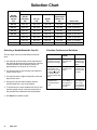
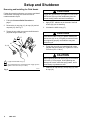
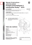
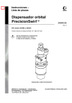
INSTRUCTIONS-PARTS LIST
This manual contains important
warnings and information.
READ AND KEEP FOR REFERENCE.
308–341
Rev. G
Supersedes F
First choice when
quality counts.
INSTRUCTIONS
Optimiser 2K
HVLP Two Component
Adhesive Spray Gun
100 psi (7 bar) Maximum Working Fluid and Air Pressure
This gun is for use with water-based contact adhesives only
Part No. 949–239, Series C
U.S. Patent Pending
02748
GRACO INC.
P.O. BOX 1441 MINNEAPOLIS, MN
COPYRIGHT 1993, GRACO INC.
Graco Inc. is registered to I.S. EN ISO 9001
55440–1441
Table of Contents
Warnings . . . . . . . . . . . . . . . . . . . . . . . . . . . . . . . . . . . . . . 2
Selection Chart . . . . . . . . . . . . . . . . . . . . . . . . . . . . . . . . 4
Air Flow and Atomizing Pressure . . . . . . . . . . . . . . . . . 5
Installation . . . . . . . . . . . . . . . . . . . . . . . . . . . . . . . . . . . . 6
Setup and Shutdown . . . . . . . . . . . . . . . . . . . . . . . . . . . 7
Ratio Check . . . . . . . . . . . . . . . . . . . . . . . . . . . . . . . . . . 13
Daily Gun Care, Flushing, and Cleaning . . . . . . . . . . 14
Troubleshooting . . . . . . . . . . . . . . . . . . . . . . . . . . . . . . . 17
Service . . . . . . . . . . . . . . . . . . . . . . . . . . . . . . . . . . . . . . 18
Parts . . . . . . . . . . . . . . . . . . . . . . . . . . . . . . . . . . . . . . . . 24
Technical Data . . . . . . . . . . . . . . . . . . . . . . . . . . . . . . . . 26
Dimensions . . . . . . . . . . . . . . . . . . . . . . . . . . . . . . . . . . . 26
Graco Phone Number . . . . . . . . . . . . . . . . . . Back Cover
Warranty . . . . . . . . . . . . . . . . . . . . . . . . . . . . . Back Cover
Symbols
Warning Symbol
WARNING
This symbol alerts you to the possibility of serious
injury or death if you do not follow the instructions.
Caution Symbol
CAUTION
This symbol alerts you to the possibility of damage to
or destruction of equipment if you do not follow the
instructions.
WARNING
EQUIPMENT MISUSE HAZARD
INSTRUCTIONS
Equipment misuse can cause the equipment to rupture, malfunction or start unexpectedly and result in
serious injury.
This equipment is for professional use only.
Read all instruction manuals, tags, and labels before operating the equipment.
Use the equipment only for its intended purpose. If you are uncertain about usage, call your Graco
distributor.
Do not alter or modify this equipment. Use only genuine Graco parts and accessories.
Check equipment daily. Repair or replace worn or damaged parts immediately.
Use this equipment only in low pressure, air spray systems.
Do not exceed the maximum working pressure of the lowest rated system component. This equipment has a 100 psi (7 bar) maximum working fluid and air pressure.
Do not lift pressurized equipment.
Use fluids or solvents that are compatible with equipment wetted parts. See the Technical Data
section of all equipment manuals. Read the fluid and solvent manufacturer’s warnings.
Comply with all applicable local, state and national fire, electrical and other safety regulations.
WARNING
PRESSURIZED EQUIPMENT HAZARD
Spray from the gun, hose leaks or ruptured components can splash fluid in the eyes or on the skin and
cause serious injury.
Do not stop or deflect fluid leaks with your hand, body, glove or rag.
Follow the Pressure Relief Procedure on page 7 when: you are instructed to relieve pressure;
stop spraying; clean, check or servicing the equipment; and install or clean fluid nozzles.
Never point the spray gun at anyone or at any part of the body.
Never put hand or fingers over the spray nozzle.
Tighten all fluid connections before operating the equipment.
Check the hoses, tubes and couplings daily. Replace worn, damaged or loose parts immediately.
Permanently coupled hoses cannot be repaired; replace the entire hose.
Route hoses away from traffic areas, sharp edges, moving parts and hot surfaces.
Do not use the hoses to pull equipment.
FIRE AND EXPLOSION HAZARD
Poor air ventilation, open flames or sparks can cause a hazardous condition and result in fire or explosion and serious injury.
Provide fresh air ventilation to avoid the buildup of flammable fumes from solvent or the fluid being
sprayed.
Extinguish all open flames or pilot lights in the spray area.
Electrically disconnect all equipment in the spray area.
Keep the spray area free of debris, including solvent, rags and gasoline.
Do not turn on or off any light switch in the spray area while operating or if fumes are present.
Do not smoke in the spray area.
Do not operate a gasoline engine in the spray area.
TOXIC FLUID HAZARD
Hazardous fluids or toxic fumes can cause serious injury or death if splashed in the eyes or on the
skin, inhaled, or swallowed.
Know the specific hazards of the fluid you are using. Read the fluid manufacturer’s warnings.
Store hazardous fluid in an approved container. Dispose of hazardous fluid according to all local,
state and national guidelines.
Dress appropriately for your application. Wear protective eyewear, noise protection for the ears, a
personal respirator, gloves and clothing.
Selection Chart
Includes:
Needle/
Nozzle/Air
Cap Kit
P/N
Needle
Assembly
P/N
Air Cap
P/N
Nozzle
P/N
Replacement
Needle Tip
P/N
Orifice Size
949–276
238–703
185–794
185–756
191–564
0.020” (0.508 mm)
949–277
238–703
185–794
185–757
191–564
0.026” (0.660 mm)
949–278
238–703
185–794
185–700
191–564
0.030” (0.762 mm)
949–279
238–217
185–794
185–701
191–016
0.042” (1.067 mm)
949–280
238–218
185–794
185–702
191–017
0.055” (1.397 mm)
949–281
238–219
185–795
185–703
191–018
0.070” (1.778 mm)
949–282
238–220
185–796
185–704
191–019
0.086” (2.184 mm)
Selecting a Needle/Nozzle/Air Cap Kit
The kits range in size to provide different fluid flow
rates.
Use the fluid nozzle that will give the required flow
with the fluid adjustment knob opened four full turns
counterclockwise and an adhesive pressure of
approximately 5 to 20 psi (0.35 to 1.4 bar).
For low flow rates or light viscosity fluid, select the
smaller nozzle sizes.
For high flow rates or high viscosity fluid, select the
larger nozzle sizes.
Using an air cap size that is smaller than the
nozzle/needle size is not recommended.
To help select the proper needle/nozzle size, a fluid
pressure gauge may be connected temporarily to
the gun fluid inlet to determine the fluid pressure.
See Service to install the parts.
Selection Problems and Solutions
PROBLEM
POSSIBLE
CAUSE
SOLUTION
Fluid pressure
required to achieve
flow rate is too high
Using set with
too small of an
orifice
Use needle/
nozzle/air cap
set with larger
orifice
Using a low pressure setting, the
fluid flow is too high,
making it necessary
to restrict needle
travel to reduce fluid
flow
Using set with
too large of an
orifice
Use needle/
nozzle/air cap
set with smaller orifice
Fluid system will not
operate at low
enough fluid pressure
Fluid regulator is
not installed or
air regulator is
not sensitive
enough
Add low pressure fluid regulator or add
more sensitive
air regulator on
pressure pot
Air Flow and Atomizing Pressure
NOTE: All tests completed with the fan air fully open.
Atomizing Air Pressure
(inlet pressure vs. atomizing pressure)
30
28
26
24
22
20
18
16
14
12
10
8
6
4
2
0
15
20
18
16
14
12
10
8
6
4
2
0
15
NOMINAL ATOMIZING PRESSURE (psi)
AIR FLOW (scfm)
Air Flow
25
35
45
55
65
75
85
95
GUN AIR INLET PRESSURE (psi)
25
35
45
55
65
75
85
95
GUN AIR INLET PRESSURE (psi)
Gun Inlet Pressure
Nominal Atomizing Pressure
15 psi (1.05 bar)
1.5 psi (0.11 bar)
Air flowing through the gun creates back pressure,
which the activator must overcome before beginning to
flow. The chart below shows the minimum activator
pressure required to overcome the atomizing air
pressure. Higher pressures may be necessary to
maintain the mix ratio.
25 psi (1.75 bar)
3.0 psi (0.22 bar)
35 psi (2.45 bar)
4.5 psi (0.33 bar)
45 psi (3.15 bar)
6.0 psi (0.42 bar)
55 psi (3.85 bar)
8.5 psi (0.62 bar)
65 psi (4.55 bar)*
10.0 psi (0.70 bar)
75 psi (5.25 bar)
13.0 psi (0.95 bar)
85 psi (5.95 bar)
15.5 psi (1.14 bar)
95 psi (6.97 bar)
18.0 psi (1.32 bar)
MINIMUM ACTIVATOR INLET PRESSURE (psi)
Atomizing Pressure Versus
Activator Inlet Pressure
30
28
26
24
22
20
18
16
14
12
10
8
6
4
2
0
15
*
25
35
45
55
65
75
85
For compliant operation, operate at 65 psi (4.55 bar) or less
95
GUN AIR INLET PRESSURE (psi)
308-341
5
Installation
E
D
G
F
N
A
S
B
R
C
M
J
H
KEY
A
B
C
Optimiser 2K Spray Gun
Air Inlet; 1/4 npsm
Air Hose
Recommend 5/16” (7.9 mm) ID hose;
Optional 3/8” (9.5 mm) ID hose
D Gun Air Shut-off Valve
E Gun Air Regulator
F Air Filter
G Air Supply Line
H Pressure Pot Air Shut-off Valve
J Pressure Pot Air Regulator
K Activator Pressure Pot
L Activator Fluid Shut-off Valve
M Activator Fluid Hose
N Activator Inlet 1/8–27 npt(f)
P Adhesive Pressure Pot
Q Adhesive Fluid Shut-off Valve
R Adhesive Fluid Hose
S Adhesive Inlet; 3/8 npsm (R3/8–19)
Q
P
L
K
J
H
02750
Fig. 1
Fluid Compatibility of Accessories
When selecting system components to supply the
adhesive and activator, consider the following:
Adhesives and activators are water-based and
corrosive. Avoid carbon steel, unplated brass,
copper, and aluminum. Stainless steel, nickelplated brass and most plastics are usually acceptable.
Piston pumps are not recommended for use with
adhesives as they are often shear sensitive and will
coagulate in your equipment. Stainless steel
pressure pots function well in place of a pump and
fluid pressure regulator. On drum or tote tank
supplied systems, plastic diaphragm pumps are
often used.
6
308-341
Some adhesives will coagulate in fluid pressure
regulators due to shear. Consult with the fluid
supplier for regulator recommendations.
Refer to Fig. 1 and see Form No. 305–591 for the
accessories recommended to install the system.
Consult with the fluid supplier or Graco for specific
recommendations.
Ventilate the Spray Booth
WARNING
FLAMMABLE/TOXIC FLUID HAZARD
To avoid hazardous concentrations of
flammable or toxic fumes, spray only in
a properly ventilated spray booth.
Comply with all applicable local, state
and national fire and safety regulations.
Installation
Air Line Accessories
Fluid Line Accessories
The gun air line must have an air regulator (E) to
control air pressure to the gun. See Fig. 1.
If the gun air source does not have a filter, install a
filter (F) on the gun air line to ensure a dry, clean
air supply.
To eliminate the need to shut off the air pressure at
the air supply, install a quick-disconnect at the gun
air inlet fitting.
If you are using diaphragm pumps to supply adhesive or activator to the gun(s), install a fluid regulator (T) on each gun fluid supply line to control fluid
pressure to the gun(s). See Fig. 9, page 9.
Install a fluid filter in the gun fluid supply lines to
avoid clogging the fluid nozzle. A 100 mesh filter is
recommended for the activator supply line to avoid
clogging the activator needle and orifice.
Use 5/32 or 1/4 inch I.D. tubing for the activator
supply line.
Setup and Shutdown
Pressure Relief Procedure
WARNING
PRESSURIZED EQUIPMENT HAZARD
The equipment stays pressurized until pressure is
manually relieved. To reduce the risk of serious
injury from pressurized fluid, accidental spray from
the gun or splashing fluid, follow this procedure
whenever you:
Q
L
02059
Fig. 2
Are instructed to relieve pressure
Stop spraying
Check, clean or service any system equipment
Install or clean fluid nozzles
1. Close the adhesive and activator shut-off valves
(Q and L). See Fig. 2.
02753
2. Trigger the gun into the spray booth* to relieve the
fluid pressures and clear excess activator from the
gun. See Fig. 3.
*
Fig. 3
D
If the gun has been flushed with solvent, be sure to spray
the solvent into a grounded metal waste container.
3. Close the atomizing air shut-off valve (D). See
Fig. 4.
02780
Fig. 4
308-341
7
Setup and Shutdown
Removing and Installing the Fluid Nozzle
Follow this procedure whenever you remove and install
a fluid nozzle. See page 4 to select a nozzle or
needle/nozzle/air cap kit.
1. Follow the Pressure Relief Procedure on
page 7.
3. Trigger the gun while you remove the fluid nozzle
(20) with the gun wrench (35).
2
Trigger the gun whenever you tighten or remove the
fluid nozzle (20) to pull the needle away from the
nozzle seating surface and avoid scratching it.
4. Apply PTFEradhesive to the threads of the fluid
nozzle (20) you are installing.
2. Remove the air cap ring (12), air cap (19), and air
cap seal (47). See Fig. 5.
1
CAUTION
5. Lubricate the baffle o-ring (17).
CAUTION
Lubricate the baffle o-ring (17) before installing the
fluid nozzle (20). A dry o-ring will prevent the nozzle
from tightening properly and adhesive may leak
inside the gun.
17
20
35
47
12, 19
6. Trigger the gun while you install the fluid nozzle
(20) with the gun wrench (35). Tighten it to 125 to
150 in-lbs (14 to 17 NSm).
CAUTION
1
Lightly lubricate baffle o-ring (17)
2
Apply PTFE adhesive to nozzle (20) threads. Trigger gun and
tighten to 125–150 in-lbs (14–17 NSm)
02757A
Fig. 5
When tightening the fluid nozzle (20), do not exceed
150 in-lbs (17 NSm) torque. Over-tightening can
damage the nozzle, affect the spray pattern, and is
unnecessary to guarantee a seal.
7. Install the air cap seal (47), air cap ring (12), and
air cap (19).
Setup and Shutdown
WARNING
EQUIPMENT MISUSE HAZARD
This gun is for use with water-based contact adhesives only. Any other use of the gun could cause
unsafe operating conditions or damage to the gun.
2. Flush the adhesive and activator fluid
lines with water and blow them out
with air before connecting them to the
gun.
3. Connect the adhesive fluid hose.
A. Connect the fluid hose (R) to the gun adhesive
inlet (S). See Fig. 8.
1. Connect the air line.
A. Connect the air hose (C) to the gun air inlet
(B). See Fig. 6.
1
S
R
1
B
C
1
1
1/4 npsm
3/8–18 npsm [R 3/8–19]
compound thread
02752
Fig. 8
02751
Fig. 6
B. Connect the other end of the air hose (C) to a
regulated air supply line (G). See Fig. 7.
NOTE: Fig. 7 shows the air supply line filter (F), air
regulator (E), and air shut-off valve (D).
G
F
B. Connect the other end of the fluid hose (R) to
a regulated fluid supply line (U–see Fig. 9) or a
pressure tank (P–see Fig. 1, page 6).
NOTE: Fig. 9 shows the fluid supply line regulator
(T) and fluid shut-off valves (Q).
U
E
T
Q
R
D
Fig. 7
C
01990
02777
Fig. 9
308-341
9
Setup and Shutdown
4. Connect the activator tube.
6. Adjust the spray pattern.
WARNING
A. Connect the fitting (V) and tube (M) to the gun
activator inlet. See Fig. 10.
B. Connect the other end of the fluid tube (M) to a
regulated fluid supply line or a pressure tank.
COMPONENT RUPTURE HAZARD
Do not exceed the 100 psi (7 bar)
maximum fluid and air pressure of this gun.
Higher pressures can cause parts to rupture and
result in serious injury.
NOTE: Refer to the Atomizing Pressure Versus
Activator Inlet Pressure chart on page 5 to help set
air and activator pressures.
A. Close the fluid adjustment valve by turning the
knob (8) fully clockwise. Then turn the knob
counterclockwise four full turns to open it. See
Fig. 12.
V
M
8
02784
Fig. 10
5. Position the Air Cap for a vertical or
horizontal spray pattern. See Fig. 11.
Open
02784
Fig. 12
B. Open the adhesive fluid shut-off valve (Q). Adjust the fluid flow with the fluid regulator (T)
installed in the gun fluid line (see Fig. 13) or
the air regulator on the adhesive tank (see Fig.
1). Typical industrial flow rates will vary with
regulator pressures from 5 to 20 psi (0.35 to
1.4 bar).
T
Vertical Pattern
Q
Horizontal Pattern
02020
Fig. 11
Fig. 13
02778
Setup and Shutdown
6. Adjust the spray pattern. (continued)
C. Hold the gun parallel to the floor and adjust the
adhesive fluid pressure until you have a 1 to 6
inch (25.4 to 152.4 mm) straight fluid stream
before the stream falls off. See Fig. 14.
D. To further reduce the volume of adhesive output at the gun, turn the fluid adjustment knob
(8) clockwise as needed. See Fig. 16. However, for the best results, adjust the adhesive
pressure or use a different size needle/nozzle/
air cap combination to change the fluid flow.
Refer to page 4.
CAUTION
Continuously spraying with the fluid adjustment knob
closed, will cause accelerated wear on the fluid
needle and trigger/air valve shaft interface.
1–6 in.
(25.4–152.4 mm)
straight fluid stream
If the fluid adjustment knob is fully closed, the gun
will emit only air and activator.
Fig. 14
02754
8
NOTE: A larger fluid nozzle at a reduced adhesive
pressure will maintain the same flow rate, but slow
down the fluid stream. See Fig. 15. This allows the
atomizing air to act on the fluid longer and improve
the atomization.
Close
Fluid Stream of Fluid Nozzles
at the Same Flow Rate
02784
Fig. 16
E. Open the pattern adjusting valve by turning the
knob (13a) fully counterclockwise. See Fig. 17.
0.042
0.055
0.070
0.086
0.110
(1.067) (1.397)
(1.778)
(2.184)
(2.794)
Nozzle Orifice Size in inches (mm)
Fig. 15
13a
02755
Close
(narrower
pattern)
Open
(wider
pattern)
02784
Fig. 17
Setup and Shutdown
6. Adjust the spray pattern. (continued)
7. Adjust the activator fluid flow.
F. Set the gun air supply pressure at 40 psi
(2.8 bar), using the gun atomizing air regulator
(E). See Fig. 18.
NOTE:
Use the fluid manufacturer recommendations if
available and refer to the Atomizing Pressure
Versus Activator Inlet Pressure chart on
page 5 when adjusting the gun.
Local laws may limit the maximum pressure to
10 psi (0.7 bar) at the air cap for HVLP compliance.
CAUTION
When the activator is being supplied to the gun, the
atomizing air must be on before triggering the gun to
avoid contaminating the atomizing air with activator.
Open the activator supply valve (L) and increase
the fluid pressure until the desired amount of activator is sprayed with the adhesive. The typical fluid
pressure range is 8 to 20 psi (0.56 to 1.40 bar).
See Ratio Check, page 13.
E
G. Hold the gun about 6 to 8 inches (150 to
200 mm) from the test piece and test the spray
pattern and atomization.
H. The spray pattern may be too wide with the
pattern adjustment knob (13a) fully open. Turn
the pattern adjustment knob clockwise until
you have the desired pattern size. See Fig. 17,
page 11.
NOTE: Some pattern air is required to supply the
activator; do not close the pattern adjustment knob
completely.
I.
L
01997
Fig. 18
Check the atomization quality again. If necessary, increase the gun air supply pressure with
the air regulator (E) in 5 psi (0.35 bar) increments until you have the desired atomization.
Fig. 19
02776
8. Shut down the system at the end of the
work-shift and before checking, adjusting, cleaning
or repairing the system. Follow the Pressure Relief Procedure on page 7.
9. Place the gun nozzle in soapy water
over-night to avoid having the tip clog with
hardened material. Do not immerse the entire gun.
J. If the atomization is still unacceptable, install a
larger fluid nozzle size to reduce the fluid
stream. Refer to Fig. 15. See page 8 to
remove and install a fluid nozzle.
K. Repeat steps 6.E to 6.J until you have the
desired spray pattern and atomization.
NOTE: To eliminate a fan pattern at low atomizing
pressures, it may help to remove the activator air
restrictor (55). See Fig. 34, page 19.
Fig. 20
02785
Ratio Check
521
NOTE: You cannot sample the adhesive and activator
at the same time. The adhesive must be checked with
the atomizing air off, while the activator must be
checked with the atomizing air on.
522
1. Check the ratio of the adhesive.
54
A. Weigh an empty beaker.
B. Close the atomizing air shut-off valve.
C. Close the activator shut-off valve.
D. Trigger the gun into the beaker for 15 seconds
to dispense the adhesive.
E. Follow the Pressure Relief Procedure on
page 7.
F. Weigh the adhesive, subtract the weight of the
beaker, then multiply the figure by 4 to obtain
the weight per minute of the adhesive.
2. Check the ratio of the activator.
A. Weigh an empty beaker.
B. Cover the beaker with a loose cover to deflect
any over-spray. See Fig. 21.
C. Disconnect the red tube from the activator
valve.
D. Connect the ratio check tube (54) (supplied
with the gun) to the activator valve outlet fitting
(521) as shown in Fig. 21. Turn the front fitting
(522) toward the front of the gun.
E. Close the adhesive shut-off valve.
F. Open the atomizing air shut-off valve.
G. Open the activator shut-off valve.
02786A
Fig. 21
H. Place the ratio check tube (54) into the beaker
as shown in Fig. 21.
I.
Direct the spray gun into the booth. Trigger the
gun for 1 minute to dispense the activator
through the tube and into the beaker.
J. Follow the Pressure Relief Procedure on
page 7.
K. Remove the beaker cover. Weigh the activator
and subtract the weight of the beaker to obtain
the weight per minute of the activator.
3. Adjust the ratio as needed.
Adjust the activator supply pressure to change the
ratio of adhesive to activator, then check the ratio
again.
Once the ratio is set, do not change the adhesive
or activator supply pressure settings or turn the
gun fluid adjustment knob. Any change to the flow
of either fluid will change the mix ratio.
Daily Gun Care, Flushing, and Cleaning
CAUTION
Do not point the gun up while cleaning it as this
may allow fluid to enter the gun air passages.
C. Point the gun down into the spray booth* and
spray until the water sprays clear. See Fig. 22.
*
If the gun is flushed with solvent, be sure to spray the
solvent into a grounded metal waste container.
Do not use metal tools to clean the air cap holes
as this may scratch them and distort the spray
pattern.
Do not immerse the gun.
Squeeze the excess fluid out of the cleaning cloth
before wiping the gun.
Typically the gun should be flushed or cleaned with
soap and water. If solvent is used, do not use methylene chloride with formic or propionic acid as it
will damage nylon components.
1. General system maintenance.
A. Clean the fluid and air line filters daily.
B. Check for fluid leakage from the gun and the
fluid hoses. Tighten fittings or replace equipment as needed.
2753
Fig. 22
D. Turn off the fluid supplies.
E. Follow the Pressure Relief Procedure on
page 7.
3. Clean the gun.
A. After relieving pressure, disconnect the activator and adhesive supply lines (M and R) from
the gun. See Fig. 23.
C. Flush the gun with water if it will not be used in
the next three days. Follow the flushing procedure below.
M
2. Flush the gun.
A. Follow the Pressure Relief Procedure on
page 7.
B. Disconnect the adhesive and activator supplies and connect the supply lines to a water
supply.
R
Fig. 23
02799
Daily Gun Care, Flushing, and Cleaning
3.
Clean the gun. (continued)
B. Disconnect the air supply line (C). See Fig. 24.
C
02800
Fig. 24
C. Remove the air cap ring (12), air cap (19), air
cap seal (47), and fluid nozzle (20) as
instructed on page 8.
20
02775A
Fig. 26
F. Clean the air cap ring, air cap, and fluid nozzle
daily, minimum, using a soft-bristle brush. See
Fig. 27. Clean out air cap holes with a soft implement, such as a toothpick, to avoid damaging surfaces.
35
47
12, 19
Fig. 25
02757A
D. Soak the air cap ring (12), air cap (19), and
fluid nozzle (20) in soapy water.
E. Dip a soft-bristle brush into soapy water, point
the gun down, and clean the front of the gun.
Do not use a wire brush. See Fig. 26.
02011
Fig. 27
308-341
15
Daily Gun Care, Flushing, and Cleaning
3.
Clean the gun. (continued)
G. Install the fluid nozzle (20) air cap seal (47), air
cap ring (12), and air cap (19) as instructed on
page 8.
Fluid needle shaft
Activator nuts, in the area where they contact
the trigger
Lubricate
H. Dampen a soft cloth with soapy water;
squeeze out the excess water. Point the gun
down and wipe off the outside of it.
Lubricate
Lubricate
02782A
Fig. 28
4. Lubricate the following gun parts daily,
using Part No. 111–265 lubricant. See Fig. 29.
16
Pattern adjustment valve threads
Fluid adjustment knob threads
Trigger pivot pin
308-341
Fig. 29
02756B
Troubleshooting
PROBLEM
CAUSE
SOLUTION
Fluid flow is fluttering while
spraying
1.
Fluid nozzle is not tight enough
1.
See page 8 to install the fluid nozzle
correctly
2.
Fluid filter is clogged
2.
Check the fluid filter
3.
Fluid adjustment knob is not
properly set
3.
Adjust the fluid adjustment knob for
less feathering or use a larger size
nozzle
4.
Baffle (item 11) is installed wrong or
damaged
4.
Check if the baffle protrusion is properly inserted into the gun insert hole, see
page 19; replace the baffle if damaged
1.
Air hose size is too restricted for higher
air flows
1.
Use larger 3/8 in. ID air hose; order part
no. 185–353
2.
Fluid pressure is too low
2.
Raise the fluid supply pressure or use
a smaller fluid nozzle
1.
Fluid nozzle is too tight
1.
See page 8 to install the fluid nozzle
correctly; replace the nozzle if
damaged
2.
Air cap is too tight
2.
Loosen the air cap retaining ring
3.
Air cap horn holes are plugged
3.
Clean the air cap horn holes with a
non-metallic item, such as a toothpick
Fluid flow fades while spraying
high viscosity fluids
Pattern becomes off-set or heavy
on ends
Fluid system will not operate at low
enough fluid pressure [below
10 psi (0.7 bar)]
There is no fluid regulator, or the air regulator on the pressure pot is not sensitive
enough at low pressures
Add a low pressure fluid regulator on the
fluid line or add a more sensitive air regulator on the pressure pot.
Adhesive residue forms on spray
nozzle
1.
Activator is dispensing in the atomizing
air
1.
Do not trigger the gun with the activator
on and atomizing air off
2.
Activator valve is leaking or not seating
properly
2.
Clean the needle, seat, and packings;
lubricate packings and re-assemble
3.
Baffle (item 11) is leaking at baffle protrusion
3.
Clean and re-assemble the baffle with
a small amount of PTFEpipe sealant
on the baffle protrusion or replace the
baffle. Make sure that the baffle protrusion is properly inserted into the gun
insert hole, see page 19
4.
Baffle is leaking at nozzle seal
4.
Clean the baffle and replace the
nozzle seal
5.
Air cap taper is not sealing to nozzle
taper
5.
Clean and re-tighten the air cap
Adhesive collecting in air passages
The adhesive nozzle’s internal seal is
leaking
Clean the nozzle and seat; see page 8
to install the fluid nozzle correctly
When the gun is triggered, the
adhesive dispenses before the activator or the activator dispenses
before the adhesive
Activator needle hex nuts are not tight
Adjust the activator needle hex nuts until
the adhesive and activator needles open
together
308-341
17
Service
8. Insert a thin-blade screw driver (A) through the
back of the gun and into the packing adjustment
nut (31) and remove the screw. See Fig. 31.
Items Needed for Service
Gun Wrench – provided
Seal Installation Tool – provided
Adjustable Wrench
Screw Driver
Part No. 111–265 Lubricant
A
Soap and water
31
NOTE: Gun Repair Kit 949–285 is available; see page
25. The following procedure covers the replacement of
all the kit parts.
Disassemble
1. Follow the Pressure Relief Procedure on
page 7.
Fig. 31
2. Remove the air cap ring (12), air cap (19), air cap
seal (47), and fluid nozzle (20) as instructed on
page 8.
9. Push the three piece packing assembly (39) out
the back of the gun with the threaded end of the
fluid needle (21). See Fig. 32.
02762
CAUTION
20
Do not use excessive force to push out the packing
assembly (39) or the u-cup seal (33) as this may
bend the fluid needle (21). Refer to Fig. 32 and 33. If
packings are difficult to remove, use a 3/16 in. plastic
rod to push them out.
35
47
12, 19
21
02757A
Fig. 30
3. Remove the nozzle seal (17). See Fig. 34.
4. Remove the fluid adjustment knob (8) and spring
(16).
5. Pull the fluid needle (21) out the back of the gun.
6. Remove the gun and activator triggers (3 and 48).
7. Remove the fluid adjustment nut (6), spring (15),
and air valve (14).
02759
Fig. 32
Service
10. Use the threaded end of the fluid needle (21) to
push out the u-cup seal (33). See Fig. 33.
11. Remove and disassemble the activator valve (49).
See Fig. 34. Use the threaded end of the activator
needle (49d) to push out the needle packings (49g
and 49r). Do not bend the end of the needle.
12. Clean the parts. Check the fluid needles (21 and
49d) for damage or excessive wear. Replace if
necessary.
21
13. Check the baffle (11) for damage. If it is damaged,
carefully pry it off with a screwdriver and replace it.
Apply part no. 514–767 Form-A-Gasket Sealant to
the front area of the gun where the baffle sits and
to the baffle protrusion. Insert the baffle protrusion
into the gun insert hole.
14. Lightly lubricate the parts indicated in Fig. 34 with
Part No. 111–265 lubricant.
02760
Fig. 33
1
49m
49p
49j
49f
49q
49h
49d 1
49e
49r
49g
49a
53
3
48
49k
49b
49
49c
51
52
55
49e
4
1
2
12
49e
19
1
47
1
5
20
1
17
11
52
33
14
1
21
1
1
4
3
1
39
1
Lightly lubricate
2
Lightly lubricate threads
3
Lightly lubricate contact area on trigger face
4
Apply part no. 514–767 Form-A-Gasket Sealant to the front area
of the gun where the baffle sits and to the baffle protrusion. Insert
the baffle protrusion into the gun insert hole.
Fig. 34
31
1
15
1
8
16
2
32
22
6
05885
308-341
19
Service
Assemble
NOTE: See Fig. 34, page 19, for the parts that need to
be lubricated.
A
31
1. Insert the fluid needle (21) through the front of the
gun as shown in Fig. 35. Install the new packing
assembly (39) by placing them on the end of the
needle tip. Orientate the packings as shown in Fig.
35.
02762
Fig. 36
4. Place the new u-cup seal (33) on the seal installation tool (42) with the u-cup lips facing the tool.
See Fig. 37.
1
2
5. Push the u-cup seal (33) into the gun until a definite snap is felt.
39
3
CAUTION
21
1
Washer
2
U-cup; lips face
down
3
Spreader
Apply even pressure to the u-cup seal (33) when
installing it to avoid damaging the seal.
33
02763
Fig. 35
1
42
2. Place the packing adjustment nut (31) over the
packing assembly and start the threads into the
gun, then remove the needle.
3. Insert a thin-blade screw driver (A) through the
back of the gun and into the packing adjustment
nut (31). See Fig. 36. Do not nick or damage parts
with the tool. Turn the screw with the screw driver
(about 3 turns); the packing will still be loose.
1
U-cup lips face the tool
Fig. 37
02023
Service
6. Slide the new air valve (14) onto the fluid needle
(21) until it is against the nut (B). See Fig. 38.
7. Install the fluid needle (21) and air valve (14) into
the back of the gun.
9. Remove the u-cup seal (32) from the fluid adjustment nut (6). See Fig. 40. Do not damage the seal
surface or the nut’s internal threads.
10. Place the new u-cup seal (32) on the seal installation tool (42) with the u-cup lips facing the tool.
See Fig. 40.
11. Push the u-cup seal (32) into the fluid adjustment
nut (6) until a definite snap is felt.
21
14
B
CAUTION
Apply even pressure to the u-cup seal (32) when
installing it to avoid damaging the seal.
12. Install the new packing ring (22).
02764
Fig. 38
8. Tighten the packing adjustment nut (31) with the
gun wrench (35) until you can feel a slight drag on
the fluid needle. See Fig. 39. Do not over-tighten
the screw as this may bind the needle movement.
1
U-cup lips face
the tool
42
22
32
31
1
35
6
02021
02758
Fig. 39
Fig. 40
Service
13. Install the spring (15) and fluid adjustment nut (6).
Tighten the nut to 25 to 35 in-lbs (2.8 to 4.0 Nm).
See Fig. 42.
18. Secure the activator valve (49) to the plate (2) with
the two screws (53). Tighten the screws to 10 to
15 in-lbs (1.1 to 1.7 Nm).
14. Install the spring (16) and fluid adjustment knob (8).
19. Place the o-ring (49e) in the groove on the plate
(2). Lightly lubricate the o-ring, and slide the plate,
with the activator valve assembly, onto the top of
the gun body.
15. Re-assemble the activator valve assembly. See
Fig. 42.
a. Make sure the thin end of the needle (49d) is
straight to avoid scratching the inside of the
nozzle.
20. Install the gun and activator triggers (3 and 48).
Tighten the screw (5) to 25 to 35 in-lbs (2.8 to 4.0
Nm).
b. Install the o-ring (49g), spreader (49r), and
activator packing nut (49h) into the housing
(49b), orientated as shown in Fig. 41. Start the
packing nut threads, then install the needle
(49d). Tighten the packing nut to 20 in-lbs
(2.3 Nm).
21. Trigger the gun to test the fluid needle (21) movement. If the fluid needle does not return after the
trigger (3) is released or returns slowly, loosen the
packing adjustment nut (31) until the needle
returns freely. See Fig. 39. Repeat this process to
test the activator needle (49d).
22. Adjust the two activator needle hex nuts (49j and
49p) as follows:
49h
49r
1
a. Pull the gun trigger (3) back until you feel
resistance against the main fluid needle (21).
49g
b. With the activator trigger (48) resting against
the gun trigger (3), screw the nuts (49j and
49p) up against the activator trigger. Tighten
the two nuts against each other in this position.
49b
1
Spreader taper faces
away from o-ring
02781A
Fig. 41
c.
Assemble the remaining parts.
d. Secure the activator housings (49b and 49a)
with the four screws (49k). Tighten them
evenly to 5 in-lbs (0.6 Nm).
CAUTION
To avoid damaging the plastic threads, do not overtighten the screws (49k).
16. Install the restrictor (55), flat side up, into the
activator outlet housing (49a).
17. Place the o-ring (49e) in the groove in the activator
outlet housing (49a). Lightly lubricate the o-ring.
c.
When properly adjusted, both fluid needles (21
and 49d) will unseat at the same time as you
pull back on the trigger.
23. Lubricate and install the fluid nozzle seal (17).
24. Install the fluid nozzle (20), air cap seal (47), air
cap ring (12) and air cap (19) as instructed on
page 8.
25. Connect the nylon tube (51) between the activator
valve outlet elbow (52) and the spray gun elbow
(52).
26. Make sure the adhesive packing assembly (39) is
sealing by spraying water at low pressure before
fully pressurizing the gun.
If the fluid packings leak, tighten the packing
adjustment nut (31) slightly and retest until the
packings seal completely.
Service
8
49m
49p
49j
2
49f
49d
49q
49h
49e
49r
49g
49c
49a
53
48
49k 9
49b
49
51
52
9
55
49e
7
2
12
19
49e
47
5
6
1
20
17
11
9
52
33
3
14
21
4
3
39
5
31
1
15
8
16
4
32
22
NOTE: See Fig. 34, page 19, for the parts that
need to be lubricated.
1
Tighten to 25–35 in-lbs (2.8–4.0 Nm)
2
Tighten to 10–15 in–lb (1.1–1.7 N.m)
3
U-cup (33) lips face air valve (14)
4
U-cup (32) lips face spring (16)
5
Tighten packing nut as needed for fluid tight seal
1
6
6
Apply PTFE adhesive to nozzle (20) threads. Trigger gun
and tighten to 125–150 in-lbs (14–17 Nm)
7
Flat side up
8
Tighten to 20 in-lbs (2.3 Nm)
9
Tighten to 5 in-lbs (0.6 Nm)
05885
Fig. 42
Parts Drawing
49m
49p
49j
Ref No. 13
Fan Air Valve Assembly
Includes items 13a–13d
49q 49h
49r
49g
49b
49f
49d
Ref No. 49
Activator Valve Assembly
Includes items 49a–49r
49n
49e
49c
53
49a
49k
48
51
49
52
52
55
12
49e
2
19
47
49e
20
17 11
5
13d
13b 1
25
13c
13a
33
4
21
14
3
39
31
1
15
16
32
22
6
1
35
Tighten to 25–35 in–lb (2.8–4.0 N.m)
NOTE: See the Service section for additional assembly
information.
8
42
02765A
Parts List
Part No. 949–239, Series C
Optimiser 2K HVLP Spray Gun
Ref
No.
Part No.
Description
1
2
3
4
5
238–139
190–247
185–761
625–723
203–953
6
8
11
12
13
188–490
185–745
275–851
276–278
236–006
13a
13b
13c*
13d*
14*
15
16
17*
19l
20l
21l
188–492
188–700
187–699
105–456
236–009
111–291
110–402
103–413
185–794
185–702
238–218
21a
22*
25
31n
32*
33*
35
39*
191–017
188–694
108–382
188–665
110–453
188–493
188–666
236–008
42
47*
48
276–268
625–722
625–725
GUN BODY
PLATE, gun
TRIGGER, gun
PIN, pivot
SCREW, lock; No. 10–24 UNC-2A
x 0.375”
NUT, fluid adjustment
KNOB, fluid adjustment
BAFFLE, pattern
RETAINING RING, air cap
FAN AIR VALVE ASSY.
Includes items 13a–13d
S VALVE, fan air
S NUT, air adjustment
S O-RING, split; PTFE r
S RETAINING RING
AIR VALVE ASSY.
SPRING, compression
SPRING, compression
SEAL, fluid nozzle
AIR CAP; 0.020–0.055 size
FLUID NOZZLE; 0.055 size
FLUID NEEDLE; 0.055 size
Includes item 21a
S NEEDLE TIP; replacement
RING PACKING; PTFE
PLUG
NUT, packing adjustment
SEAL, u-cup; UHMWPE
SEAL, u-cup; UHMWPE
WRENCH, gun
PACKING ASSY.; includes
u-cup spreader, u-cup seal
and packing washer
TOOL, seal installation
SEAL, air cap
TRIGGER, activator valve
Qty
1
1
1
1
1
1
1
1
1
1
1
1
1
1
1
1
1
1
1
1
1
1
1
1
1
1
1
1
1
1
1
1
Ref
No.
Part No.
Description
49n
949–217
49a
49b
49c
49dn
49e*
49f*
49g*
49h
49j
49k
625–730
625–729
188–762
949–295
106–555
112–931
103–154
188–665
188–772
113–411
49m
49p
49q
49r*
51*
514–619
112–930
112–929
188–494
187–169
52n
53
54
514–581
514–655
625–779
55*
191–015
ACTIVATOR VALVE ASSY.
Includes items 49a–49r
S HOUSING, activator outlet
S HOUSING, activator inlet
S INSERT, nozzle
S NEEDLE ASSY., activator valve
S O-RING; Vitonr
S SPRING, compression
S O-RING; ethylene propylene
S NUT, packing
S NUT, hex
S SCREW, cap, SST;
10–24 x 3/4”
S NUT, acorn; nylon
S NUT, hex
S WASHER
S SPREADER
TUBE; nylon;
5/32 in. (3.97 mm) O.D.
CONNECTOR, tube
SCREW, cap; 10–32 x 1”
TUBE, ratio check;
24” (609.6 mm); not shown
RESTRICTOR, orifice
Qty
1
1
1
1
1
3
1
1
1
1
4
1
1
1
1
1
4
2
1
1
* These parts are included in Repair Kit 949–285,
which may be purchased separately.
n Keep these spare parts and the Repair Kit on hand
to reduce down time.
l See chart on page 4 for other available Needles,
Nozzles, and Air Caps.
Technical Data
Maximum Working Fluid
and Air Pressure . . . . . . . . . . . . . . . . . . . . 100 psi (7 bar)
Weight . . . . . . . . . . . . . . . . . . . . . . . . . . . 17.5 oz. (0.5 kg)
Air Inlet . . . . . . . . . . . . . . . . . . . 1/4–18 npsm (R1/4–19)
compound thread
Adhesive Inlet . . . . . . . . . . . . . 3/8–18 npsm (R3/8–19)
compound thread
Activator Inlet . . . . . . . . . . . . . . . . . . . . . . . 1/8–27 npt(f)
Wetted Parts
Adhesive and Activator . . . 304 and 17–4 Stainless
Steel, Acetal, Nylon,
Ultra High Molecular
Weight Polyethylene
Activator Only . . . . . . . . . . . . Buna-N, Nickel-plated
Brass, Anodized
Nylon (air cap only)
Dimensions
6.39 in.
(163 mm)
8.0 in.
(203 mm)
Manual Change
Summary
Corrected the reference numbers in the parts drawing.
Notes
The Graco Warranty and Disclaimers
Graco warrants all equipment listed in this manual which is manufactured by Graco and bearing its name to be free from defects in
material and workmanship on the date of sale by an authorized Graco distributor to the original purchaser for use. With the exception of
any special extended or limited warranty published by Graco, Graco will, for a period of twelve months from the date of sale, repair or
replace any part of the equipment determined by Graco to be defective. This warranty applies only when the equipment is installed,
operated and maintained in accordance with Graco’s written recommendations.
This warranty does not cover, and Graco shall not be liable for general wear and tear, or any malfunction, damage or wear caused by
faulty installation, misapplication, abrasion, corrosion, inadequate or improper maintenance, negligence, accident, tampering, or
substitution of non-Graco component parts. Nor shall Graco be liable for malfunction, damage or wear caused by the incompatibility of
Graco equipment with structures, accessories, equipment or materials not supplied by Graco, or the improper design, manufacture,
installation, operation or maintenance or structures, accessories, equipment or materials not supplied by Graco.
This warranty is conditioned upon the prepaid return of the equipment claimed to be defective to an authorized Graco distributor for
verification of the claimed defect. If the claimed defect is verified, Graco will repair or replace free of charge any defective parts. The
equipment will be returned to the original purchaser transportation prepaid. If inspection of the equipment does not disclose any defect
in material or workmanship, repairs will be made at a reasonable charge, which charges may include the costs of parts, labor, and
transportation.
Graco’s sole obligation and buyer’s sole remedy for any breach of warranty shall be as set forth above. The buyer agrees that no other
remedy (including, but not limited to, incidental or consequential damages for lost profits, lost sales, injury to person or property, or any
other incidental or consequential loss) shall be available. Any action for breach of warranty must be brought within two (2) years of the
date of sale.
GRACO MAKES NO WARRANTY, AND DISCLAIMS ALL IMPLIED WARRANTIES OF MERCHANTABILITY AND FITNESS FOR
A PARTICULAR PURPOSE IN CONNECTION WITH ACCESSORIES, EQUIPMENT, MATERIALS OR COMPONENTS SOLD BUT
NOT MANUFACTURED BY GRACO. These items sold, but not manufactured by Graco (such as electric motors, gas engines,
switches, hose, etc.), are subject to the warranty, if any, of their manufacturer. Graco will provide purchaser with reasonable assistance
in making any claim for breach of these warranties.
In no event will Graco be liable for indirect, incidental, special or consequential damages resulting from Graco supplying equipment
hereunder, or the furnishing, performance, or use of any products or other goods sold hereto, whether due to a breach of contract,
breach of warranty, the negligence of Graco, or otherwise.
FOR GRACO CANADA CUSTOMERS
The parties acknowledge that they have required that the present document, as well as all documents, notices and legal proceedings
entered into, given or instituted pursuant hereto or relating directly or indirectly hereto, be drawn up in English. Les parties
reconnaissent avoir convenu que la rédaction du présente document sera en Anglais, ainsi que tous documents, avis et procédures
judiciaires exécutés, donnés ou intentés à la suite de ou en rapport, directement ou indirectement, avec les procédures concernées.
Graco Phone Number
TO PLACE AN ORDER, contact your Graco distributor, or call this number to identify the distributor closest to you: 1–800–367–4023 Toll Free
All written and visual data contained in this document reflects the latest product information available at the time of publication.
Graco reserves the right to make changes at any time without notice.
Sales Offices: Minneapolis, Detroit, Los Angeles
Foreign Offices: Belgium, Canada, England, Korea, France, Germany, Hong Kong, Japan
GRACO INC.
P.O. BOX 1441 MINNEAPOLIS, MN
55440–1441
PRINTED IN U.S.A. 308–341 December 1993, Revised April 1997