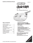
1
Model 1022/1024
Includes
Remote Control
(Up to 7 Single Button Programmable Controls Available)
Safety Beam System must be installed to close door.
For use only with sectional doors. Your Residential
Operator comes with a Rail Assembly which is standard for
up to a 7 foot high door.
Homelink® and Car2U™ compatible
For Answers and Assistance:
1.800.354.3643
or visit www.geniecompany.com
SAVE THIS MANUAL FOR FUTURE REFERENCE
Homelink® is a registered trademark of Johnson Controls Technology Company.
Car2U™ is a trademark of Lear Corporation.
PN# 3642036212, 8/09/2007
SAFETY INFORMATION
OVERVIEW OF
POTENTIAL HAZARDS
Garage doors are large, heavy objects that move with the help of springs under high tension and electric motors. Since moving
objects, springs under tension, and electric motors can cause injuries, your safety and the safety of others depend on the owner
or user of this system to read, understand and implement the information in this manual. If you have questions or do not
understand the information presented, contact The Genie Company or an authorized Genie Dealer.
In this section and those that follow, the words DANGER, WARNING, and CAUTION are used to emphasize important safety
information.
The word:
DANGER indicates an imminently hazardous situation which, if not avoided, will result in death or serious injury.
WARNING indicates an potentially hazardous situation which, if not avoided, could result in death or serious injury.
CAUTION indicates an potentially hazardous situation which, if not avoided, may result in injury or property damage.
The word NOTE is used to indicate important steps to be followed, important considerations, or location of parts.
POTENTIAL
HAZARD
EFFECT
PREVENTION
WARNING:
Keep people clear of opening while door is moving.
Can Cause
Serious Injury
or Death
Do NOT allow children to play with the door operator.
Do NOT operate a door that jams or one that has a broken spring.
MOVING DOOR
Turn OFF power before removing operator cover.
WARNING:
Can Cause
Serious Injury
or Death
When replacing cover, make sure wires are not pinched or near
moving parts.
Operator must be properly grounded.
ELECTRICAL
SHOCK
WARNING:
Can Cause
Serious Injury
or Death
HIGH
SPRING
TENSION
2
Do NOT try to remove, repair or adjust springs or anything to which
door spring parts are fastened, such as, wood blocks, steel brackets,
cables or other like items.
Repairs and adjustments must be made by a trained professional service
technician using proper tools and instructions.
PN# 3642036212, 8/09/2007
TABLE OF CONTENTS
OPERATOR FEATURES
SECTION . . . . . . . . . . . . . . . . . . . . . . . . . . . . . . . . . . . . . . . . . PAGE
SAFETY INFORMATION . . . . . . . . . . . . . . . . . . . . . . . . . . . . . . . . . 2
OPERATOR FEATURES . . . . . . . . . . . . . . . . . . . . . . . . . . . . . . . . . 3
SAFETY FEATURES . . . . . . . . . . . . . . . . . . . . . . . . . . . . . . . . . . . . 3
PRE-INSTALLATION CHECK LIST . . . . . . . . . . . . . . . . . . . . . . . 4-5
RECOMMENDED TOOLS . . . . . . . . . . . . . . . . . . . . . . . . . . . . . . . . 6
PARTS IDENTIFICATION . . . . . . . . . . . . . . . . . . . . . . . . . . . . . . . 6-7
INTELLICODE® Rolling Code Security System.
An electronic rolling code system that enhances the security of
the door operator by continuously changing the access code
each time the remote control is used. The door operator
responds to each new code only once. An access code copied
from a working system and tried again will not control the door
operator.
Lighted Wall Button*.
Operates door operator from inside garage.
(Refer to section 3)
ARRANGING BOXES . . . . . . . . . . . . . . . . . . . . . . . . . . . . . . . . . . . 8
SAFETY INFORMATION . . . . . . . . . . . . . . . . . . . . . . . . . . . . . . . . . 9
INSTALLATION
1 OPERATOR ASSEMBLY . . . . . . . . . . . . . . . . . . . . . . . . . . 9-10
2 INSTALLATION . . . . . . . . . . . . . . . . . . . . . . . . . . . . . . . . 11-13
and Car2U™ compatible.
Follow the Homelink® or Car2U™ instructions in your car
owner’s manual.
3 WALL CONTROL INSTALLATION . . . . . . . . . . . . . . . . . 14-15
4 SAFETY BEAM SYSTEM INSTALLATION . . . . . . . . . . . 16-17
5 CONNECTING TO POWER . . . . . . . . . . . . . . . . . . . . . . . . . 18
ADJUSTMENTS
SAFETY FEATURES
6 LIMIT SWITCHES & FORCE ADJUSTMENT . . . . . . . . . 19-20
CONTACT REVERSE TEST. . . . . . . . . . . . . . . . . . . . . . . . . 20
7 PROGRAMMING REMOTE CONTROLS. . . . . . . . . . . . . . . 21
8 BATTERY/VISOR CLIP INSTALLATION . . . . . . . . . . . . . . . 22
9 LIGHT BULB AND LENS INSTALLATION . . . . . . . . . . . . . . 22
SAFETY INSTRUCTIONS . . . . . . . . . . . . . . . . . . . . . . . . . . . . . . . 23
MAINTENANCE & TROUBLESHOOTING
10 ROUTINE MONTHLY MAINTENANCE . . . . . . . . . . . . . . . . 23
WIRING DIAGRAM . . . . . . . . . . . . . . . . . . . . . . . . . . . . . . . 24
TROUBLESHOOTING GUIDE - OPERATOR . . . . . . . . . . . 25
TROUBLESHOOTING GUIDE - POWER HEAD LED . . . . . 26
TRANSMITTER COMPLIANCY STATEMENT. . . . . . . . . . . . . . . . 27
WARRANTY . . . . . . . . . . . . . . . . . . . . . . . . . . . . . . . . . . . . . . . . . . 28
Safety Beam Non-Contact Reversing System**.
Puts an invisible beam across the door opening. The door stops
and reverses to the full open position if anything passes
through the beam. Red or green LED indicator lights on the
power head provide a self diagnostic code if an operational
problem exits. (Refer to Section 10.)
Safe-T-Reverse® Contact Reversing System.
Automatically stops and reverses a closing door within 2
seconds of contact with an object. (Refer to Section 6.)
Safe-T-Stop® Timed Reversed System.
Automatically opens a closing door if it fails to close completely
within 30 seconds.
Force Guard™ Control.
Features adjustable open and close force settings. For
maximum safety, these must be set to the minimum force
required to fully open and close the door. (Refer to Section 6.)
Relay Monitoring System.
Automatically stops and reverses a closing door if the closing
relay malfunctions.
Watch Dog™ Monitoring System.
Automatically stops and reverses a closing door if the Safety
Beam System** has an operational problem.
*Operator MUST be installed with the
included Wall Control.
**Safety Beam Safety Reverse System
MUST be installed to close door.
Automatic Lighting System.
One bulb lighting supplies up to 60 watts of light for safer
evening exits and entries. Turns ON when door is activated and
automatically turns OFF 3 minutes later.
Manual Emergency Release.
Manually releases door from door operator. Use during a power
failure or other emergency to allow manual opening and closing
of door.
PN# 3642036212, 8/09/2007
3
PRE-INSTALLATION CHECK LIST
FOR HELP-1.800.354.3643 OR WWW.GENIECOMPANY.COM
Things to consider if you are planning to "Do-it-yourself."
This operator is designed for use with SECTIONAL doors only.
In many cases you will be replacing an existing door operator with a new one, however, if this
will be the first operator installed there are some pre-installation issues which need to be
addressed. They are as follows:
The Genie Company recommends that you read and fully understand all information and
instructions contained herein before choosing a "Do-it-yourself" installation. Any
questions should be directed to The Genie Company or an authorized Genie Dealer.
(The issue numbers below refer to the circled numbers in the illustrations on page 5.)
Check your ceiling where the power
head of your new unit will be mounted.
Plan how you will be mounting the power head.
It is possible that ceiling joists may not be in the
position needed with respect to the garage door
operator. It may be necessary to add an
additional bracket and fasteners (not included
with your new door operator kit). (Refer to
Section 2.)
1
Check the wall directly above the garage
door. The door operator’s header bracket
must be securely fastened to this wall. Insure
that the structure will provide a strong mounting
location.) (Refer to Section 2.)
2
3
Check to see if the mounting location
for the Safety Beam System is clear from
obstruction and has a wood surface available
for attaching the mounting brackets. The
brackets may be attached to concrete if necessary
but extra tools and special fasteners (not supplied)
will be required. (Refer to Section 4 and 5.)
You need a 110-120 Volt power supply
available. The outlet should be no more than 3
feet from the power head once it is mounted (Refer
to Section 5.)
5
WARNING
DO NOT USE AN EXTENSION CORD!
DO NOT USE A PORTABLE GENERATOR! This
product is designed to operate on
standard house current.
DO NOT USE ALTERNATE POWER SUPPLIES.
6
To avoid damage to your door and/or
operator, make sure you disable and/or
remove any door locks, ropes, and/or cables
prior to installing your operator. (Refer to
Section 1.)
Remove
Remove
7
Insure that your door is properly balanced
and moving freely. (Refer to Section 2.)
NOTE: Mounting brackets must be installed
within code specifications.
Is your sectional garage door made of
aluminum, light-weight steel, fiberglass
or glass panels? Additional support bracing
must be added to these type doors. If this is the
case, please contact the door manufacturer or
authorized dealer so that they can furnish you
with a "bracing kit." (Refer to Section 2.)
4
WARNING
To reduce the risk of injury to persons or
damage to property - Use this operator only
with sectional doors.
4
WARNING
If your door jambs, binds, is improperly
balanced or has a broken spring, have it
repaired or adjusted by a trained professional
service technician. Door springs, cables,
pulleys, brackets and associated hardware are
under extreme tension and can cause serious
injury or death.
(NOT SHOWN) If your garage does not have
a separate entry door, you should consider
an emergency release kit (GER-2) for installation on
your garage door.
8
PN# 3642036212, 8/09/2007
TYPICAL SECTIONAL DOOR INSTALLATION
5
1
Pg. 18
FOR HELP-1.800.354.3643 OR WWW.GENIECOMPANY.COM
Pg. 12
2
TYPICAL
SUPPORT
BRACKET
Pg. 11-12
ADDED
HEADER BRACKET
MOUNTING BOARD
BRACES
POWER CORD
(APPROX. 45 IN.)
TO 120V GROUNDED
OUTLET
EXTENSION SPRING
OR
TORSION SPRING
4
NOTE: This operator is designed for
use with SECTIONAL doors only.
Pg. 13
Pg. 16-17
Pg. 16-17
6
3
3
Pg. 10
SAFETY BEAMS
MAX. 6"
MIN. 5"
7
Pg. 11
SECTIONAL DOOR
WARNING
To reduce the risk of injury to persons or
damage to property - Use this operator only
with sectional doors.
PN# 3642036212, 8/09/2007
5
RECOMMENDED TOOLS
FOR HELP-1.800.354.3643 OR WWW.GENIECOMPANY.COM
Pencil
3/16" Drill Bit
Carpenter’s level
Drill
Wire strippers
Adjustable wrench
Ratchet
Tape measure
Step ladder
Safety Glasses
1/4", 7/16", 3/8" and
1/2" Sockets
Phillips screwdrivers
Hammer
PARTS IDENTIFICATION - Not Shown Full Size .
ARRANGING BOX CONTENTS FOR ASSEMBLY
ORGANISATION DU CONTENU DE LA BOÎTE POUR LE MONTAGE
DISPOSICIÓN DEL CONTENIDO DE LA BOLSA PARA EL MONTAJE
Remove internal boxes.
Enlever les boîtes internes.
Quite las cajas internas.
Remove lens Box and motor power head.
Enlever la boîte des lentilles et la tête motorisée.
Quite la caja de la lente y el motor de la caja de control.
Carefully remove third rail (with chain
attached) and place on floor.
Enlever soigneusement le troisième rail (avec la
chaîne attachée) et le placer sur le sol.
Cuidadosamente quite el tercer riel (con la
cadena acoplada) y ponga en el piso.
Arrange three small boxes for easy access.
Arranger les trois petites boîtes de manière à pouvoir y accéder facilement.
Disponga las tres cajas pequeñas para tener acceso
fácil.
Remove rail sections not connected
to chain.
Enlever les sections de rail non connectées
à la chaîne.
©Overhead Door Corporation 06/2007
Quite las secciones de riel no conectadas a
la cadena.
Arrange rails in line and pull plastic sleeve off chain.
Arranger les rails en ligne et tirer sur le manchon en plastique
pour le dégager de la chaîne.
Disponga los rieles en línea y estire la camisa de plástico fuera
de la cadena.
Follow instructions in the Installation Manual for assembly steps.
Child can be pinned under automatic garage door.
Death or serious injury can result.
.
• Never let child walk or run under moving door.
• Never let child use door opener controls.
• Always keep moving door in sight.
If
person
is
pinned,
push
control
button
or
use
•
emergency release.
door opener monthly:
• Test
Refer to your owner' s manual.
’
Place 11/ 2-inch object (or 2x4 laid flat) on floor.
If door fails to reverse on contact, adjust opener.
If opener still fails to reverse door, repair or replace opener.
Do not remove or paint over this label.
Mount wall control out of child's reach (at least 5 feet above floor).
Place next to wall control.
©1999
Procéder selon les instructions stipulées dans le manuel d'installation pour les étapes de
montage à suivre.
Si l i t
i
lM
l d i t l ió
l
d
t j
Safety Brochures
Box Contents Sheet
Wire
Safety Beam Source
with wire
(Red LED)
Insulated Staple
Entrapment Warning
Label
Header Bracket
Door
Bracket
Safety Beam Sensor
with wire
(Green LED)
Rail Section Clamp
Safety Beam
Source/Sensor Bracket
Head Rail Section
Center Rail Section
Wall Control Button
End Rail Section
Door Arm
Three-button
Remote Control
6
PN# 3642036212, 8/09/2007
FASTENERS - Shown Full size (See Parts List below for full description.)
BAG NO.
0
DESCRIPTION
QUANTITY
RAIL SECTION CLAMP
2
RAIL CLAMP BOLT – 5/16''-18 x 5/8''
8
HEX FLANGE NUT – 5/16''-18
8
1
BOLT – 5/16''-18 x 1/2''
3
2
CLEVIS PIN, LONG – 5/16" x 3"
1
COTTER PIN
1
HEADER BRACKET
1
LAG SCREW – 5/16'' x 2''
2
HEX BOLT – 5/16''-18 x 3/4''
5
HEX FLANGE NUT – 5/16''-18
5
LAG SCREW – 5/16'' x 2''
2
SELF DRILLING SCREW – 1/4''-20 x 3/4''
3
DOOR BRACKET
1
HEX BOLT – 5/16''-18 x 3/4''
3
SELF LOCKING NUT – 5/16''-18
1
HEX FLANGE NUT – 5/16''-18
2
CLEVIS PIN – 5/16" x 3/4"
1
COTTER PIN
1
WALL CONTROL BUTTON ASSEMBLY
1
PAN HEAD PHILLIPS SCREW – #4-24 x 1''
2
7
13 MM INSULATED STAPLE
30
8
SAFETY BEAM SOURCE/SENSOR BRACKET
2
PHILLIPS HEX SCREW – #10-16 x 1- 1/4''
4
WIRE NUT (GREY)
4
REMOTE WITH BATTERY
1
SAFETY BEAM SOURCE/SENSOR & WIRE SET
1
NO NUMBER
LIGHT COVER - WHITE
1
NO NUMBER
LIGHT COVER - COLOR
1
3
4
5
6
NO NUMBER
NO BAG
Rail Clamp Bolt - 5/16"-18 x 5/8"
#10-16 x 1-1/4" Phillips Hex Screw
#4-24 x 1" Pan Head
Phillips Screw
Lag screw - 5/16" x 2"
Wire Nut
Clevis pin, long
5/16" x 3"
Clevis pin
5/16" x 3/4"
Self Locking Nut
- 5/16"-18
Cotter pin
Self-drilling Screw
1/4"-20 x 3/4"
Hex Flange Nut
- 5/16"-18
Hex Bolt - 5/16"-18 x 3/4"
Hex Flange Nut
- 1/4"-20
Hex Bolt - 5/16"-18 x 1/2"
Shoulder Bolt
- 5/16"-18 x 1"
MISSING ANY PARTS? Please call toll free - 1.800.354.3643
DO NOT RETURN TO POINT OF PURCHASE.
IMPORTANT! - Information needed when calling
• Model number - (located on packaging)
• Store, city, state, and date of purchase
PN# 3642036212, 8/09/2007
7
1-PIECE RAIL HARDWARE ASSEMBLED VIEW
FOR HELP-1.800.354.3643 OR WWW.GENIECOMPANY.COM
Power Cord
Rail with chain
Power Head
Trolley Slide
Nh
at
SIO
Nor
De ined
a tra ons
G TE
jury by cti
RINus Inbe maded instru
Release
Knob
TE ed
NOors nect
do nta or
me Co r
So cing. utofor
er
bra distrib
tur s.
or
do nufacction
ma tru
ins
an
rio
H eSP
Se mustr tools
us ents pe
HIG
Ca tm pro
Chain tensioner
Ca
n
or
irs
pa
Re e pe
vic
ser
jus
ad using
n
rso
Chain
Header
Bracket
Clevis Pin, Long
& Cotter Pin
3-PIECE RAIL HARDWARE ASSEMBLED VIEW
Power Cord
Rail with chain
Rail Clamps
Power Head
Trolley Slide
Rail Clamp Bolts
Release
Knob
End Rail
ON h
NSI
TE
at d
De
or traine s
ry by a ction
Injumade instru
d
us
rio st be an
Se ts mu r tools
pe
use tmenpro
n Ca jus ng
Ca or ad n usi
irs rso
pa
Re vice pe
ser
G
RIN
H SP
HIG
Chain tensioner
Rail Clamp Nuts
TE ed
NOors nect
do nta or
me . Co tor
So acingtribu for
br dis turers.
or
do nufacction
mainstru
Center Rail
Chain
Header
Bracket
8
Clevis Pin, Long
& Cotter Pin
PN# 3642036212, 8/09/2007
IMPORTANT INSTALLATION INSTRUCTIONS
WARNING: To reduce the risk of severe injury or death:
1. READ AND FOLLOW ALL SAFETY, INSTALLATION
AND OPERATION INSTRUCTIONS. (If you have
questions or do not understand an instruction, call The
Genie Company or an authorized Genie Dealer.)
2. Install only on a properly balanced sectional garage door.
An improperly balanced door could cause severe injury.
Have a professionally trained service technician make
repairs to cables, spring assemblies, and other hardware
before installing the opener.
3. Remove all ropes and remove or make inoperative all
locks connected to the garage door before installing opener.
4. Where possible, install the door opener 7 feet or more
above the floor. For products having an emergency
release, mount the emergency release 6 feet above the floor.
1
OPERATOR ASSEMBLY
5. Do NOT connect the operator to source of power
until instructed to do so.
6. Locate the control button:
• Within sight of door,
• At minimum height of 5 feet so small children are not
able to reach it, and
• Away from all moving parts of the door.
7. Install the Entrapment WARNING Label next to the
control button in a prominent location. Install the
Emergency Release Marking on or next to the
emergency release.
8. After installing the opener, the door must reverse when
it contacts a 1-1/2 inch high object (or a 2 x 4 board laid
flat) on the floor.
FOR HELP-1.800.354.3643 OR WWW.GENIECOMPANY.COM
RAIL ASSEMBLY: Use a clean, flat surface.
WARNING
To reduce the risk of injury to persons or
damage to property - Use this operator only
with sectional doors.
#4
CAUTION
Do NOT run until operator is fully assembled.
NOTE: Three (3) piece rail assemblies are for a 7
foot high door.
Clear a workspace area to unpack and organize box
and contents for assembly.
1. There are 4 boxes inside the carton. Each box is
numbered 1 - 4. Note that some operators will
contain the same parts and be packaged with
fewer boxes. Carefully remove the three
internal boxes (Labeled #1, 2, and 3) and place
them on the floor for easy access. (Fig. 1-1).
These boxes contain assembly parts and the
contents are organized by assembly tasks. For
quick reference inside the lid of each box there is
a label illustrating the components inside.
2. Remove the motor power head and place it on
the floor for later use. Remove box #4 and
place it on the floor for later use.
Rail Connectors
Bag 0
Bag 2
Header Bracket
Rail Connector Bolts
Header Bracket
Bolts
Rail Connector Nuts
E
Nth
SIO
Dea d
or traine s
TEN
ry by a ction
INGInjumade instru
ous be and
H SPR
Seri s musttools
se
HIG
Cau ment roper
Lag Srews
NOT s need
act
door
Cont r or
Someng. butofor
bracidistri rers.
door factu
ction
manu
instru
Bolts
Bag 1
Bag 3
Rail
Mounting
Straps
5/16" Nuts
& Bolts
Power head
NOTE: For 1-piece rail—skip to POWER HEAD &
RAIL ASSEMBLY on the next page.
Box Label Example
FIG. 1-1
PN# 3642036212, 8/09/2007
Internal boxes.
9
NOTE: For split rail clamps, nuts, and bolts
locate Bag 0 from Box 1.
3. Remove the two rail sections that are not
connected to the chain and place them on
floor (Fig. 1-2, A).
4. Carefully remove the third rail section with
chain and plastic sleeve. Place rail section on
floor and extend chain straight out. (Fig. 1-2,
B). Chain and rail should extend approximately 7
feet.
5. Remove wire ties and plastic bag from chain.
Leave chain extended straight out on floor.
Avoid kinks in the chain by careful handling and
keeping chain flat on the floor.
6. Align the three rail sections by pulling the
chain straight and wrapping it around the
chain tensioner pulley (Fig. 1-3).
7. Attach the two rail clamps to the rail section
joints with (4) bolts and nuts. After both rail
clamps have been assembled to the rail sections,
securely tighten the bolts and nuts.
Chain Rail
Center Rail
A
End Rail
B
Wire Tie(s)
FIG. 1-2
Split Rail sections.
Rail with chain
Rail Clamps
Rail Clamp Bolts
Release
Knob
End Rail
HIGH
Rail Clamp Nuts
IONath
NS
De ed
or a train
G TE
ury by ions
RINs Inj ande instruct
SP iou t be mad
s
TE d
NO rs nee
tactor
e doo
. Contor
Somcing ribu r for
brar dist ture s.
doo ufac tion
ruc
man
inst
Ser
mus tool
per
use ents
g pro
n Ca stm
usin
Ca or adju
on
airs
Rep ice pers
serv
Chain tensioner
Center Rail
Chain
FIG. 1-3
Split Rail assembly.
Use
5/16"-18 x 1/2"
Bolts
POWER HEAD & RAIL ASSEMBLY
NOTE: Handle carefully! Drive chain can slide out
of rail.
NOTE: For power head and rail assembly locate
Bag 1 from Box 1.
1. Attach rail assembly to power head by aligning
the sprocket onto the motor shaft. Use (3)
bolts, 5/16"-18 x 1/2" (Fig. 1-4).
2. Tighten the chain by turning the adjustment
nut clockwise. The chain adjustment nut is
located opposite the power head at the other end
of the rail (Fig. 1-5).
3. Tighten chain until chain is approximately 1/8
inch above the base of the rail at midpoint on
the rail (Fig. 1-5). Do NOT over tighten chain.
FIG. 1-4
Rail - Power head assembly.
Chain Pulley Bracket (at wall end of rail)
Use 1/2" socket
on adjustment nut
Tighten nut to move pulley this direction
Chain
Chain
1/8"
REMINDER: You should have removed all ropes
and/or cables and disabled the door lock already.
If you have not, remove all ropes and/or cables
and disable garage door lock NOW before
continuing with installation (Fig. 1-6).
T-Rail at center of rail assembly
FIG. 1-5
Chain adjustment.
Remove
Set assembled power head and rail aside. Begin with
Section 2 INSTALLATION.
Remove
FIG. 1-6
10
PN# 3642036212, 8/09/2007
Disable garage door lock.
T-Rail
2
INSTALLATION
FOR HELP-1.800.354.3643 OR WWW.GENIECOMPANY.COM
b) - extend
vertical line
HEADER AND DOOR
MOUNTING BRACKETS:
2-1/2"
CAUTION
Header bracket must be fastened to garage
framing. Do NOT fasten to drywall, particle
board, plaster or other such materials.
1. Finding header bracket mounting location.
• Close garage door.
– Use a pencil and level.
a) Mark center of garage door (one-half overall
width) on the wall with 6" vertical line at top
edge of door.
b) Continue this line on wall above door for
about 12" (Fig. 2-1, a).
• Raise garage door until top edge of door
reaches its maximum height (Fig. 2-2).
• With door at highest point.
– Measure height from top edge of door to floor
(Fig. 2-2).
• Close door again.
• Mark height measurement on wall above door
(Fig. 2-1, c).
– Make your mark across vertical line made earlier.
• Add 2-1/2" to height mark just made on wall. This
is location for header bracket (Fig. 2-1, d).
d) - final
height mark
c) - door at
highest point
top of door
in closed
position
FIG. 2-1
a) - 6" vertical
line
Final height mark.
HIGHEST POINT OF TRAVEL
2-1/2"
HEADER
TRACK
WARNING
Door springs are under high tension. If spring or
its shaft is in the way, measure 2-1/2" above
spring or shaft on the garage door centerline and
mark this height as your location for header
bracket.
Do NOT move door spring!
NOTE: If header bracket location needs to be
above header for garage door opening, you need
to add a "mounting surface." A 2" x 6" board
securely attached (board and fasteners not
included) to wall studs on either side of your mark
is sufficient (Fig. 2-3).
NOTE: For header bracket and bolts locate Bag 2
from Box 1.
NOTE: The bolts supplied in Bag 2 are designed
to be used on pressure treated lumber.
2. Mounting the header bracket.
• Hold header bracket against wall (Fig. 2-3).
• Position bracket as shown.
– Place center on vertical line.
– Bottom edge on final height line.
• Mark screw hole locations on wall.
• Drill 3/16" pilot holes at each screw hole mark.
– Fasten header bracket with 2 lag screws
(provided) (Fig. 2-3).
SECTIONAL
DOOR
HEADER
HIGHEST POINT OF TRAVEL
TRACK
FROM HERE
TO FLOOR
FIG. 2-2
final hei
SECTIONAL
DOOR
FROM HERE
TO FLOOR
Finding highest point of travel.
ght mar
k
final he
ig
mark ht
2-1/2"
door at hi
ghest po
int
FIG. 2-3
PN# 3642036212, 8/09/2007
door at
highest
point
Header bracket mounting (on header &
above header).
11
MOUNTING THE OPERATOR:
HEADER BRACKET
1. Getting started.
• Position assembled rail on wall next to header
bracket. (Fig. 2-4).
– Place material on floor under power head to
protect from scratching. (A box, stool, or
similar device may be needed to clear a
torsion spring.)
VIEW
FROM ABOVE
(not to scale)
NOTE: For header bracket pins locate Bag 2
from Box 1.
2. Mounting the assembly.
• Attach rail to header bracket using clevis pin
and cotter pin.
• Support power head on step-ladder to prevent
interference with header mounted spring
(Fig. 2-5).
NO
NO
YES / SÍ / OUI
FIG. 2-4
Position assembly and align.
COTTER PIN
NOTE: Before final attachment to ceiling, insure
that assembly is in proper alignment (Fig. 2-4).
NOTE: For nuts, bolts, and lag screws locate
Bag 3 from Box 1.
• On finished ceilings, locate ceiling joists or
trusses using a stud finder or similar device.
Attach angle iron (not provided) to joists or
trusses through finish material using (provided)
lag screws (Fig. 2-6).
• On unfinished ceilings or open ceilings, straps
may attach directly to joists or trusses.
Depending on the garage construction, extra
framing material (not provided) may be
required which should be installed using
appropriate construction techniques
(Fig. 2-6).
NOTE: Refer to your local building codes for
appropriate construction techniques.
• Attach mounting straps to ceiling using lag
bolts (Fig. 2-6).
• Set height of power head to following:
(Fig. 2-6).
a) Rail must clear door at door’s highest point
of travel.
b) Be level or power head slightly below level.
• Securely tighten power head mounting bolts
and nuts.
• Lower door.
• Check that rail clamp bolts and nuts are tight.
• DO NOT PLUG UNIT IN YET!
CLEVIS PIN
FIG. 2-5 Rail mounting to header bracket.
ANGLE IRON ON FINISHED CEILING
DRYWALL
Attach angle iron to beams
UNFINISHED OR OPEN BEAM
Extra framing
not needed
Mounting Straps
(not provided)
bolts & nuts
bolts & nuts
FIG. 2-6
12
PN# 3642036212, 8/09/2007
Extra framing
NEEDED
Mounting the power head.
DOOR BRACKET:
CAUTION
Doors made of masonite, lightweight wood,
fiberglass, and sheet metal must be properly
braced before mounting door operator. Contact
door manufacturer or distributor for a bracing kit.
The Genie Company is not responsible for
damage caused due to improperly braced door.
NOTE: For door bracket and bolts locate Bag 4
from Box 2.
1. Finding door bracket mounting location.
• Door bracket is mounted as high on door as
possible along vertical centerline and NO LOWER
THAN top set of rollers (Fig. 2-7).
2. Mounting the door bracket.
• Proper bracing should be verified at this point.
– Align door bracket centered on your vertical
centerline (Fig. 2-8).
– Attach using 3 self-drilling screws for sheet
metal or other light weight material.
– Use lag screws (not provided) for solid
wooden sectional doors.
centerline
centerline
even with or
above top roller
FIG. 2-7
Mounting door Bracket.
centerline of top roller
A
FIG. 2-8
B
Examples of door bracket positioning.
NOTE: For solid wood doors, carriage bolts
WITHOUT SLOTTED HEADS (not included) may
also be used for attaching door bracket.
INSTALL DOOR ARMS
NOTE: For door arm nuts and bolts, clevis and
cotter pins locate Bag 5 from Box 2.
1. Attach the arms.
• Fasten curved door arm to door bracket using
bolt and locking nut. (Fig. 2-9).
• Fasten straight arm to carriage using clevis pin
and cotter pin. (Fig. 2-9).
short clevis pin & cotter pin
2. Connecting the arms.
• Slide carriage back and forth to adjust arm length.
– Position the straight arm 50º down from the
rail.
• With the arms arranged in this position, fasten
arms together using bolts and nuts spaced as
far apart as possible (Fig. 2-9).
50°
bolts as far
apart as
possible
FIG. 2-9
PN# 3642036212, 8/09/2007
Attaching door arms.
13
3
WALL CONTROL INSTALLATION
FOR HELP-1.800.354.3643 OR WWW.GENIECOMPANY.COM
Wire from
power head
to wall control.
WARNING
Verify there is NO power to the operator before
installing wall control wires and wall control.
CAUTION
Staples which are too tight can cut or pinch wires.
Cut or pinched wires can cause the wall control to
stop working. When using the insulated staples,
make sure you fasten them only as tightly as
needed to hold the wire snugly.
Wall
control
WARNING
Use of any other wall control can cause the door to
operate unexpectedly and the light not to work.
Use only the included wall control.
NOTE: For Wall Control, wire and insulated
staples locate Bags 6 and 7 from Box 2.
1. Wall Control location.
• Wall Control location should be in direct sight
of door.
• It should be at least five feet (5') above floor to
prevent small children from operating door.
• It must be away from any moving parts. (You
should NOT be able to reach the garage door
while standing at wall control.)
• Wall Control board screw connections are
polarized, (+) positive and (-) negative.
2a. Wiring (If pre-wired).
• Locate wall control pre-wired wire ends
(Fig. 3-1). (They should be located within the
guidelines mentioned above.)
• Split and strip ends of wire (Fig. 3-2).
• Fasten wire to wall control board screws on back
of wall control.
– White wire to the + (plus) terminal.
– White striped wire to the - (minus) terminal.
2b. Wiring (If NOT pre-wired).
• Pick a convenient location for mounting
wall control using the guidelines mentioned
above. (Fig. 3-1)
• Run wire from wall control to power head
(Fig. 3-1).
• Split and strip ends of wire (Fig. 3-2).
• Fasten wire to control board screws on back of
wall control button.
– White wire to the + (plus) terminal.
– White striped wire to the - (minus) terminal.
14
"Entrapment"
warning label
Separate
entry door
FIG.3-1
EXAMPLE ONLY!
This is an example of wire routing
when NOT pre-wired. Your wire
routing may be different.
Wall control wire routing
2"
1/2"
or B
or W
FIG. 3-2
PN# 3642036212, 8/09/2007
Splitting and stripping.
3.Securely fasten wires.
• Securely fasten wires to ceiling and
wall using insulated staples provided.
– Use insulated staples.
Insulated
– Staples should be snug only.
Staple
• If rear cover is attached to power head,
remove it.
• On power head:
– Route wall control wires through wire guide.
– Split and strip ends of wire (Fig. 3-2 on
previous page).
– Insert wire into terminal holes and lightly press in
the orange locking clips above each terminal
hole. (You can use a pencil or small screwdriver
to comfortably press in locking clips.) The white
wire into #2 terminal hole and striped wire into
the #1 terminal hole.
– Confirm wire lock by lightly tugging on the wire.
The wire should remain in the terminal hole.
• Do NOT install rear cover yet.
Locking
Clips
Terminal
Holes
6 5 4 3 2 1
6 5 4 3 2 1
+P –B
InfaredSensor
(Power Head With Rear Cover Removed)
FIG. 3-3 Insert wires.
4. Mounting.
• Fasten wall control to wall with 2 screws
(provided) (Fig. 3-4).
• Remove protective backing from "Entrapment"
warning label (Fig. 3-5). The "Entrapment" label
is located in the center of this manual.
– Stick label on wall near wall control.
FIG. 3-4
Mounting wall control.
FIG. 3-5
Mounting Entrapment warning label.
PN# 3642036212, 8/09/2007
15
4
SAFETY BEAM SYSTEM INSTALLATION
FOR HELP-1.800.354.3643 OR WWW.GENIECOMPANY.COM
WARNING
There should be no electrical power to the operator
while installing Safety Beam wires. If you have
plugged in the power cord—UNPLUG IT NOW!
NOTE: The operator will not close the door
automatically unless the Safety Beam System is
installed.
NOTE: For Sensors, screws, wire, and insulated
staples locate items and Bag 8 from Box 3.
1. Mounting brackets.
• Mark both sides of garage door frame or wall no
higher than 6" and no lower than 5" above floor.
(Fig. 4-1).
• Hold bracket against door frame or wall.
– Check if brackets extend out from wall far
enough, so tongue of bracket is beyond door,
tracks or any door hardware.
– If not:
a) Mounting bracket extensions are available
through an authorized Genie dealer.
b) Blocks of wood, etc. may be substituted for
extensions.
• Center bracket on your mark (Fig. 4-2).
• Fasten each with 2 screws (Fig. 4-2).
NOTE: Mounting brackets can be attached to the
floor or concrete rim using concrete anchors
(not provided).
2. Mounting Safety Beam Source (Red LED) and
Sensor (Green LED).
• If garage has only one garage door.
– Determine which side of garage receives most
direct sunlight (Fig. 4-4).
– Red LED should always be on sunny side
whenever possible (Fig. 4-4).
• For multiple doors.
– Preventing crossed signals is critical.
– Place source and sensor modules on adjacent
doors facing in opposite directions (Fig. 4-4).
NOTE: To help prevent interference from sun,
Safety Beam sensor with Green LED may be
placed further away from the door opening where
it will spend more time in shadow.
• Slide source/sensor onto tongue of bracket until
it clicks into place. (Fig. 4-3).
mark
FIG. 4-1 Mark door frame.
e
slid
FIG. 4-2
Mounting brackets.
SUN
RED
LED
GREEN
LED
GREEN
LED
Insulated
Staple
16
FIG. 4-3 Attach
sensors to brackets.
RED RED
LED LED
GREEN
LED
GREEN
LED
TWO DOOR
GARAGE
ONE DOOR
GARAGE
RED
LED
GREEN GREEN
LED
LED
RED RED
LED LED
THREE DOOR
GARAGE
FIG. 4-4
Safety Beam source and sensor
locations.
Red
3a. Wiring (If NOT pre-wired).
• Route wire from Safety Beam sensors to power
head using method shown in (Fig. 4-5a).
• Securely fasten wires to wall and ceiling
as you go (Fig. 4-6 on next page).
– Use insulated staples.
– Staples should be snug only.
bracket
tongue
center of
bracket
Source
Green
Sensor
6 5
Power
Head
4 3
2 1 or
6 5
4 3
Dashed Line = striped wire
Solid Line = white wire
FIG. 4-5a Source and sensor wiring methods.
PN# 3642036212, 8/09/2007
2 1
3b. Wiring (pre-wired).
• Route wire from wall to Safety Beam sensors.
(Fig. 4-5b).
• Splice pre-wiring to shortened sensor wire,
match wire pairs dash-to-dash and
plain-to-plain.
- Trim sensor wire to approximately one foot
(1 ft) from sensor.
- Split and strip ends of sensor wires and
pre-wired wires. (Fig. 4-7)
- Splice wires together with (provided)
wire nuts.
• Route wire from ceiling to power head. Wire Nut
(Fig. 4-5b).
• Securely fasten wires where they exit
wall and ceiling as you go.
– Use insulated staples.
– Staples should be snug only.
Insulated
Wall
Wall
Red
Green
Source
Sensor
Ceiling
6 5
2 1 or 6 5
4 3
FIG. 4-5b Pre-Wired source and sensor wiring
methods.
Insert Wire
Into Connector
Wire
Wire
CAUTION
Use this
wire routing
if NOT pre-wired
Staples which are too tight can cut or pinch wires.
Cut or pinched wires can cause the Safety Beam
System to stop working. When using the insulated
staples, make sure you fasten them only as tightly
as needed to hold the wire snugly.
Sensor
Locking
Clips
Invisible Light Beam
Protection Area
Sensor
FIG. 4-6 Wire routing.
FIG. 4-7
Splitting and stripping.
2"
1/2"
6 5 4 3 2 1
FIG. 4-8
Insert wires.
Terminal
Holes
2 1
Dashed Line = striped wire
Solid Line = white wire
Power
Head
Staple
4. Split and strip ends of sensor wires (Fig. 4-7).
NOTE: For rear cover locate Box 4.
5. Attach Safety Beam wire to power head wire
terminal.
• Route Safety Beam wires through wire guide.
– Insert wire into terminal holes and lightly press
in the orange locking clips above each terminal
hole. (You can use a pencil or small
screwdriver to comfortably reach in and lightly
press down locking clips.) Insert white wires to
'even' terminal holes and striped wires into
'odd' terminal holes (Fig. 4-8).
4 3
+P –B
InfaredSensor
(Power Head With Rear Cover Not Shown)
6 5 4 3 2 1
– Confirm wire lock by lightly tugging on the wire.
The wire should remain in the terminal hole.
• Install rear cover. The rear cover is the same
color as the power head clips and body
(Fig. 4-9).
• Do not install the white (lamp) cover at this time.
NOTE: Safety Beam alignment check must be
performed following connection to electrical
power (see page 18). DO NOT PLUG IN YET!
Cover clips
FIG. 4-9 Install rear cover.
PN# 3642036212, 8/09/2007
17
5
CONNECTING TO POWER
FOR HELP-1.800.354.3643 OR WWW.GENIECOMPANY.COM
WARNING
• To reduce the risk of electrical shock, this equipment
has a grounded type plug that includes a third
(grounding) pin. This plug will only fit a grounded type
outlet. If you do not have a grounded outlet, contact
a qualified licensed electrician to install one. DO NOT
alter the plug in any way. The door operator must be
properly grounded in order to prevent personal injury
and damage to the components.
• DO NOT remove motor cover. All work performed
on motor must be done by a trained professional
service technician.
FIG. 5-1 Connect to power.
Motor Cover Screws
CAUTION
FIG. 5-2
Remove motor cover.
• Check local building codes to make sure that you
are not required to have your garage door operator
permanently wired, with circuit breaker protection. If
building codes require door operator to be
permanently wired have a qualified licensed
electrician connect power with permanent wiring.
FIG. 5-3
Power cord strain relief.
WITH GROUNDED PLUG:
Plug the operator into a properly grounded
electrical outlet. (Fig. 5-1)
CAUTION
• Do NOT use an extension cord.
• Do NOT use a portable generator. This product
is designed to operate using standard
household current.
• Do NOT use alternate power supplies.
WITH PERMANENT WIRING:
Instructions for Electrician.
• Remove power from circuit.
• Remove rear cover and motor cover.
– Remove four motor cover screws (Fig. 5-2).
• Remove existing power cord and strain relief
from the 7/8" dia. hole and discard. (Fig. 5-3)
• Connect permanent wiring to power head using
7/8" diameter hole.
– White to white/black to black/ground to green.
– Use only UL recognized wire nuts.
• Wires inside the power head must be at least 6"
in length.
• Replace motor cover and rear cover and
re-energize the circuit.
NOTE: The Genie Company is not responsible for
charges resulting from work preformed by an
independent electrician.
WITH POWER SUPPLIED:
Check Safety Beam alignment (Fig. 5-4).
• Insure that no part of door or its hardware is
in path between lenses of source and sensor.
• Insure that tops of lenses are between 5" - 6"
above the floor (Fig. 5-4). The brackets are
flexible, and can be adjusted slightly if needed.
• Adjust the Red LED transmitter by aiming the
unit directly at the Green LED receiver. Use the
adjustment screw located on the top of the
transmitter housing to make adjustments.
• The Red LED transmitter will blink if there is a
misalignment. When the LED units are aligned
the Red LED will remain ON continuously.
• After the alignment is finished tighten the
adjustment screws on both sensors.
18
lo
om f
5" f r
or
FIG. 5-4 Check Safety Beam Alignment.
INFRARED PROTECTION FUNCTION
1. When the garage door is opening, its movement
will not be influenced if the safety beam is
obstructed.
2. If the safety beam is obstructed before the
garage door closes, the door will not close.
3. When the garage door is closing, if safety beam is
cut off by people or obstacle, the garage door will
reverse automatically to its fully opened position.
(Meanwhile, the opener light will keep blinking until
door moves to its fully opened position.)
4. If the Safety Beam System fails, loses power, or
is installed improperly, you will have to press
and hold the wall control "close" button until the
door reaches its fully closed position. The LED
indicator light on the power head will be green
and blink twice (Pattern: ☼☼ pause ☼☼ pause)
to inform you to eliminate problem first.
Otherwise, the door will reverse automatically to
its fully opened position if you release the
"close" button on the wall control during the
closing movement.
PN# 3642036212, 8/09/2007
6
DOOR LIMITS
FOR HELP-1.800.354.3643 OR WWW.GENIECOMPANY.COM
WARNING
• Severe injury or death can result if the door
closing force is set too high.
• Never increase the door closing force above the
minimum required to move the door.
• Never adjust force to compensate for a sticking
or binding door.
• Once per month perform CONTACT REVERSE
TEST as described on the next page and in
Section 10.
Limit Controls location
on power head.
LED
Indicator Light
Open
Travel Limit
SETTING & TESTING OPEN/CLOSE LIMITS
The OPEN (UP) and CLOSE (DOWN) door positions
are controlled by making the adjustments on the
panel located on the bottom of the power head. The
adjustments that can be made are:
Close Travel Limit,
Open Travel Limit,
Maximum Closing Force,
Maximum Opening Force, and
Transmitter Programming.
ENGAGE CHAIN TO CARRIAGE
To
Garage Door
Open
Set Limit
Button
OPEN
Up Force
Control
Adjustment
SET
LEARN MANUAL LIMIT FORCE
SET
Learn
Code
Button
CODE
Close
Travel Limit
1. Press and hold the "Close Travel Limit" button
until the chain advances and engages carriage
(Fig. 6-2).
FIG. 6-1
Close
Set Limit
Button
CLOSE
Down Force
Control
Adjustment
Limit controls.
CLOSE TRAVEL LIMIT
1. Press and hold the "Close Travel Limit" button
until the door is fully closed.
2. You can quickly press and release the "Close
Travel Limit" button to move the door in small
increments. You can also use the "Open Travel
Limit" button to move the door slightly in the
UP direction.
3. Door is fully closed when the bottom edge of door
presses firmly onto the ground.
4. Once the door is in the desired position, press and
release the "Down SET Limit" button. The
LED indicator light light will blink green once. This
stores the closed position in memory.
SET
Carriage
Chain - Master Link (engages to carriage)
FIG. 6-2
Engage Chain to Carriage.
OPEN TRAVEL LIMIT
1. Press and hold the "Open Travel Limit" button
to move the door to its fully opened position. This
starts the opener moving in the UP direction.
2. Hold the "Open Travel Limit" button until the
door is in the fully opened position that you desire,
then release this button.
3. You can quickly press and release the "Open
Travel Limit" button to move the door in small
increments. You can also use the "Close Travel
Limit" button to move the door slightly in the
DOWN direction.
4. Once the door is in the desired position, press
and release the "Open SET Limit" button.
The LED indicator light will blink green twice.
This stores the opened position in memory.
SET
PN# 3642036212, 8/09/2007
19
CARRIAGE LOCK
DOOR
The Carriage Lock can be manually engaged or
disengaged.
• To disengage Carriage Lock
– Pull handle towards opener.
• To engage Carriage Lock
– Pull handle towards door.
UP/DOWN FORCE
1. By turning the Down Force Control clockwise,
the DOWN force can be increased. By turning
the Down Force Control counter-clockwise,
the DOWN force can be decreased. Set the
DOWN force level at the minimum force required
to close door without reversing.
2. Once the desired level is selected, this stores the
maximum force level for the DOWN direction in memory.
3. By turning the Up Force Control clockwise, the
UP force can be increased. By turning the Up Force
Control counter-clockwise, the UP force can be
decreased. Set the UP force level at the minimum
force required to open door without stopping.
4. Once the desired level is selected, this stores
the maximum force level for the UP direction
in memory.
CLOSE
UNLOCK
LOCK
CLOSE
TO RELEASE
PULL TOWARD
THE OPENER
FIG. 6-3
TO RECONNECT
PULL TOWARD
DOOR
Engage/Disengage Carriage Lock.
OPEN
OPEN
OPEN
ROTATE
CLOCKWISE
FORCE
ERASE - OPEN/CLOSE TRAVEL LIMIT
1. Press and hold both of the "SET" buttons
( & ) together until the green indicator
light blinks (about 5 seconds).
2. All close and open travel limit settings are
erased. Then follow the steps above to
reprogram close and open travel limits.
NOTE: The operator will not close the door
automatically unless the Safety Beam System
is installed.
Up Force
Control
Adjustment
SET
ROTATE
COUNTER-CLOCKWISE
SET
CLOSE
Down Force
Control
Adjustment
FIG. 6-4
Force Control Adjustment.
FIG. 6-5
2 x 4 under center of door opening.
CONTACT REVERSE TEST
The force adjustments and limit switch settings
MUST BE COMPLETED before testing.
1. Testing.
• Open garage door using wall control.
– Place a 2" x 4" board (laid flat) under center
of garage door opening (Fig. 6-5).
• Close door using wall control.
• When door contacts board, it must stop and
reverse (within 2 seconds) to open position.
2. Adjustment.
• If the door does not properly reverse.
– Check to see if door has "close" limit
programmed. It should not have reached its
"close" limit before hitting board.
– If the door STOPS but does not reverse,
decrease "CLOSE FORCE" control
setting slightly (turn it counter-clockwise).
• Test again. Repeat as necessary.
CLOSE
20
PN# 3642036212, 8/09/2007
7
PROGRAMMING REMOTE CONTROLS
WARNING
A moving door can cause serious injury or death.
1. Keep people clear of opening while door is
moving.
2. Do NOT allow children to play with Wireless
Keypad.
3. During programming, the door opener could
begin to run, so stay away from the moving
door and its parts. To keep the door from
moving, close the door and disconnect it from
the Opener by pulling the Emergency Release.
NOTE: For remote control locate Box 3.
1a. Single Button Remote Programming.
NOTE: This operator can learn up to 7 single
button remote controls.
• Locate learn code button and indicator LED
on the power head (next to force adjustment
screws) (Fig. 7-1).
• Press and release learn code button.
– Indicator LED will blink RED at a rate of twice
per second.
• Within 30 seconds, push remote control
button once.
– Indicator LED will stop blinking and stay on.
• Press remote control button again.
– Red LED will go out. Remote is now
programmed.
1b. Multi Button Remote Programming.
NOTE: Each button on a multi-button remote is
designed for use with 1 door. You cannot
program 2 buttons to operate the same door, nor
can you program 1 button to operate 2 doors.
You can program a maximum of 7 different
transmitters or wireless devices.
NOTE: Pushing two buttons simultaneously will
erase programmed memory and limits must be reset.
• For each button.
– Program each button separately using the
Single Button Remote Programming steps.
2. Operating.
• Press remote button once.
– Door will move.
• Press button again.
– Door will stop.
• Press button again.
– Door will move in opposite direction.
NOTE: The door will stop automatically at the
fully open or fully closed position.
NOTE: To program a
Homelink® and Car2U™
device follow the Homelink® or Car2U™
instructions in your car owner’s manual.
FCC and IC CERTIFIED
This device complies with FCC Part 15 and RSS 210
of Industry Canada. This equipment has been tested
and found to comply with the limits for a Class B
digital device, pursuant to Part 15 of the FCC Rules.
These limits are designed to provide reasonable
protection against harmful interference in a residential
installation. This equipment generates, uses and can
radiate radio frequency energy and, if not installed
and used in accordance with the instructions, may
cause harmful interference to radio communications.
However, there is no guarantee that interference will
not occur in a particular installation. If this equipment
does cause harmful interference to radio or television
reception, which may be determined by turning the
equipment OFF and ON, the user is encouraged to
try to correct the interference by one or more of the
following measures:
• Re-orient or relocate the receiver antenna.
• Increase the separation between the operator
and receiver.
• Connect the operator into an outlet on a circuit
different from that to which the receiver is
connected.
• Consult your local dealer.
Limit controls location
on power head.
LED
Indicator Light
To
Garage Door
Open
Set Limit
Button
OPEN
Up Force
Control
Adjustment
SET
LOST OR STOLEN REMOTE
1. Clear memory.
• Press and hold learn code button (on power
head) for 10 seconds or until the red blinking
indicator LED goes out.
• Program remaining or new remote controls as
done previously. Your door operator will no
longer recognize any signal received from the
missing remote control, or any other which has
not been reprogrammed.
Open
Travel Limit
LEARN MANUAL LIMIT FORCE
SET
Learn
Code
Button
FIG. 7-1
PN# 3642036212, 8/09/2007
CODE
Close
Travel Limit
Close
Set Limit
Button
CLOSE
Down Force
Control
Adjustment
Learn code button and LED
21
8
REMOTE CONTROL BATTERY REPLACEMENT AND VISOR CLIP INSTALLATION
1. Battery replacement.
• Use coin, ball-point pen or similar device.
– Gently push straight in on battery cover lock
tab as shown (Fig. 8-1).
• Flip open battery cover.
– Remove old battery.
• Make sure new battery is facing proper direction
(Match battery polarity with symbols inside
battery cover) (Fig. 8-2).
– Recommended replacement battery type:
Alkaline A23, 12 volt.
• Slip new battery into place.
– Snap battery cover shut.
• Operate remote to make sure it is working
properly. (No re-programming is needed.)
2. Visor clip.
You will have to install the visor clip if you
choose to carry your remote attached to the car
visor.
• Slide visor clip into back of remote control.
– It will snap into place (Fig. 8-3).
Slide out
FIG. 8-1
Open battery cover.
– and + polarity marks
FIG. 8-2 Match battery polarity.
FIG. 8-3
9
Attach visor clip.
LIGHT BULB / LENS INSTALLATION
NOTE: For lens cover locate Box 4.
1. Light bulb.
• Recommendations.
– Do NOT use a short neck bulb.
– Light bulb should be no more than 60 Watts.
– Use a heavy duty service bulb for longer life.
• Screw bulb into socket.
2. Lens.
• Select the white (lamp) cover. Do NOT use the
colored cover in this location.
• Line up lamp lens tabs on power head with
corresponding slots in lens (Fig. 9-1).
• Slide lens onto power head. Make sure the tabs
are fully engaged into lens slots (Fig. 9-2).
• Plug power cord back into electrical outlet.
22
PN# 3642036212, 8/09/2007
Light bulb
Lens tabs
FIG. 9-1
Slide lens onto motor cover.
FIG. 9-2
Fasten lens.
IMPORTANT SAFETY INSTRUCTIONS
WARNING:
To reduce the risk of severe injury or death:
1. READ AND FOLLOW ALL INSTRUCTIONS.
2. Never let children operate or play with the door controls. Keep the remote control away from children.
3. Always keep the moving door in sight and away from people and objects until the door is completely
closed. NO ONE SHOULD CROSS THE PATH OF THE MOVING DOOR.
4. NEVER GO UNDER A STOPPED, PARTIALLY OPEN DOOR.
5. Test operator monthly. The door MUST reverse on contact with a 1-1/2" high object (or a 2" x 4" board
laid flat) at the center of the doorway on the floor. After adjusting either the force or the limit of travel,
retest the door Opener. Failure to adjust the Opener properly may cause severe injury or death.
6. When possible, use the emergency release only when the door is closed. Use caution when using this
release with the door open. Weak or broken springs are capable of increasing the rate of door closure
and increasing the risk of severe injury or death.
7. KEEP DOORS PROPERLY BALANCED. See your garage door Owner’s Manual. An improperly
balanced door increases the risk of severe injury or death. Have a trained professional service
technician make repairs to cables, spring assemblies, and other hardware.
8.
SAVE THESE INSTRUCTIONS.
If you have any questions, please do not hesitate to contact customer service at:
1.800.354.3643
10
MAINTENANCE
WARNING
•
•
Garage door hardware (springs, cables,
brackets, pulleys, etc.) are under extreme
pressure and tension.
DO NOT attempt to repair or adjust door springs
or any hardware, and DO NOT OPERATE garage
door automatically or manually if door is
improperly balanced or springs are broken.
– CONTACT A TRAINED PROFESSIONAL
SERVICE TECHNICIAN.
ROUTINE MONTHLY MAINTENANCE
2. Contact reverse.
• Place a 2" x 4" board laid flat on floor.
– In center of garage door opening.
• Close door by using wall button or
remote control.
– Door fails to reverse on contact with board
(See section 7 "CONTACT REVERSE.")
– Operator still fails
CONTACT THE GENIE COMPANY OR AN
AUTHORIZED GENIE DEALER.
3. Safety Beam System.
• Red LED blinks.
– check alignment (See section 5 ).
1. Door balance.
• With the door closed, pull emergency release
knob (Carriage Lock) towards the opener to
release door from carriage assembly.
• Raise door manually approximately 3'- 4' and
release.
– Door should remain stationary or move very
slightly.
– If door moves quickly, HAVE DOOR SERVICED
BY A PROFESSIONAL.
• Close the door.
• Pull emergency release knob towards door to
engage carriage.
– Operate door using remote.
– Door will re-attach itself to carriage assembly.
CAUTION
Use wall control supplied with operator. Any other wall control can cause
the operator to operate unexpectedly.
PN# 3642036212, 8/09/2007
23
CIRCUIT WIRING DIAGRAM
FOR HELP-1.800.354.3643 OR WWW.GENIECOMPANY.COM
Operator circuit wiring diagram. This wiring diagram is for reference only.
Opening Cover May Cause Electric Shock.
Remove power from operator prior to removing cover.
WARNING
POWER CORD
CORDON DE SECTEUR
CABLE ELÉCTRICO
TERMINAL BLOCK
SURGE PROTECTOR (MOV)
BORNE
BLOQUE DE TERMINALES
LIMITEUR DE SURTENSION
PROTECTOR DE SOBRETENSIONES
WHITE
TRANSFORMER
BLANC
BLANCO
TRANSFORMATEUR
TRANSFORMADOR
PRIMARY
BLACK
SECONDARY
PRIMAIRE
PRIMARIO
NOIR
NEGRO
SECONDAIRE
SECUNDARIO
BLACK
NOIR
NEGRO
VERT
VERDE
MOTOR
BLANC
BLANCO
RED
CAPTEUR DE PASSAGE
SENSOR DE PASILLO
BLACK
ROUGE
ROJO
NOIR
NEGRO
GREEN
VERT
VERDE
YELLOW
1
2
BLANC
BLANCO
ORANGE
BLUE
ORANGE
ANARANJADO
BLEU
AZUL
BLACK
NOIR
NEGRO
WHITE
VERT
VERDE
GREEN
JAUNE
AMARILLO
JAUNE
AMARILLO
HALL SENSOR
MOTEUR
MOTOR
YELLOW
ROUGE
ROJO
ROUGE
ROJO
BLACK
GREEN
WHITE
RED
RED
NOIR
NEGRO
1
2
3
1
6
5
4
STRIPED WHITE
BLANC RAYÉ
BLANCO RAYADO
3
2
2
3
4
1
STRIPED WHITE
BLANC RAYÉ
BLANCO RAYADO
WARNING
PHOTO SENSOR
PHOTODÉTECTEUR
FOTOSENSOR
ELECTRICAL
SHOCK
24
PN# 3642036212, 8/09/2007
WALL BUTTON
BOUTON MURAL
BOTÓN DE LA PARED
TROUBLESHOOTING GUIDE - OPERATION
PROBLEM
FOR HELP-1.800.354.3643 OR WWW.GENIECOMPANY.COM
WHAT TO DO
Operator does NOT run
from wall control.
• Check power source.
– Plug a lamp into outlet used for power head. If lamp works, power source is OK.
– If not, check fuse or circuit breaker.
• If power is OK.
– Check connections at power head terminals.
– Check connections at wall control.
• Check for broken or cut wires. Staples can cut insulation and short wires. Repair or replace.
Door operator starts
for no reason.
• Was a remote control lost or stolen? Erase all remote control codes from receiver
memory and reprogram (See section 7 ).
• Button stuck on wall control or remote.
• Check CLOSE limit switch setting (See section 6 ).
• Wires shorted. Staples can cut insulation and short wires. Repair or replace.
Door starts down, then
STOPS before it’s
closed.
• Check CONTACT REVERSE (See section 6 ).
• Check garage door for binding.
• Wires shorted. Staples can cut insulation and short wires. Repair or replace.
Door starts down, then
STOPS and goes back
up.
• If a NEW installation, check Door Arm position (See section 2 ).
• Check Safety Beam system for beam obstruction or misalignment of lenses
(See section 3 ).
• Check if Safety Beam Red LED is flashing.
• Check "CLOSE FORCE" adjustment (See section 6 ).
• Check garage door for binding.
Door will only run
closed.
• Check "OPEN FORCE" adjustment (See section 6 ).
• Check door condition and door spring.
• WARNING: If you suspect a problem with the garage door hardware or springs, contact
an authorized Genie Dealer or a trained professional service technician, or contact The
Genie Company at 1-800-35-GENIE.
Door will only run open.
• Check "CLOSE FORCE" adjustment (See section
Door starts up, but
STOPS before it’s
completely open.
• Be sure door, operator, and springs are in good repair, properly lubricated and
balanced (See maintenance section).
• Check "OPEN" limit setting (See section 6 ).
• Check "OPEN FORCE" adjustment (See section 6 ).
• WARNING: If you suspect a problem with the garage door hardware or springs, contact
an authorized Genie Dealer or a trained professional service technician, or contact The
Genie Company at 1-800-35-GENIE.
• Make sure carriage is engaged to carriage slide.
– Place carriage lever in lock position.
• Check to make sure chain is not broken or OFF its track.
• Check FORCE ADJUSTMENT (See section 6 ). Door operator will NOT run more
than 30 seconds each way if door does not move.
Operator runs, but
door does NOT move.
6 ).
Remote control has
less than 25 feet
operating range or no
operation.
• Relocate remote control inside car and or point remote control at garage door.
• Replace battery (See section 8 ).
• Reposition door operator antenna.
• Red LED blinks while button is being pushed or LED does not come on - battery
is low, replace battery.
Operator works from
wall control, but NOT
from remote control.
• Program remote control code into receiver memory. (See section
• Replace remote control battery with good one. (See section 8 ).
Noisy operation.
• Be sure all fasteners are tight.
• Be sure door and operator is in good repair, properly lubricated and
balanced (See monthly maintenance section).
Safety Beam System
malfunction.
• If an operational problem exists, and operator will not run closed. The operator
can be forced to close as follows (See section 5 ). Hold the wall control button
down until door is completely closed.
• Check Safety Beam System alignment.
• Replace Safety Beam System Sensors.
• Disconnect the Safety Beam System from the operator and call for repair service.
PN# 3642036212, 8/09/2007
7 ).
25
TROUBLESHOOTING GUIDE - POWER HEAD LED
Power head LED
Red LED
Green LED
showing
showing
OFF
OFF
FOR HELP-1.800.354.3643 OR WWW.GENIECOMPANY.COM
Possible Problem
Normal operation
None required
Continuous ON
• Programming incomplete
• Complete programming
1 BLINK, Pause
(Repeat)
• Transmitter has not learned
• Push button to program
• Programming incomplete
• Safety Beam sensor
obstruction going down
• Door obstruction going down
• Door obstruction going up
• Set DOWN LIMIT programming
• Check for obstruction, remove
• Programming incomplete
• Wire to power head or wire
connection at power head is
bad.
• Sensors out of alignment
• Continuous obstruction
• Set UP LIMIT programming
• Check power head wiring, check
connections,
– Replace or repair
3 BLINKS, Pause
(Repeat)
• Limits set backwards
• Clear limits and reprogram
(See section 6 )
4 BLINKS, Pause
(Repeat)
• Push button wire short
• Check push button and wiring.
Staples can cut insulation and shorts
wires. Repair or replace push button
and/or wiring.
– Contact The Genie Company at
1-800-35-GENIE
• Reverse wire placement in power
head connector. (See section 3 )
1 BLINK, Pause
(Repeat)
2 BLINKS, Pause
(Repeat)
• Push button wires reversed
in power head connector.
5 BLINKS, Pause
(Repeat)
• Chain is too tight
• Control system failure
• Thermal Protector activated
26
Solution
PN# 3642036212, 8/09/2007
• Check for obstruction, remove.
– Check door spring
– Contact The Genie Company at
1-800-35-GENIE
• Check Source & Sensor alignment
• Check for obstruction
• Adjust chain tension (See section 1 ).
– Contact The Genie Company at
1-800-35-GENIE
• Contact factory authorized dealer for
service
• Wait until Thermal Protector cools
and resets. NOTE: The 5 BLINKS
pattern will remain blinking until
the next operator activation. If the
Thermal Protector does not reset.
– Contact factory authorized dealer
for service.
TRANSMITTER COMPLIANCE STATEMENT
Transmitters comply with all United States and Canadian legal requirements as of the date of manufacture. No warranty is made
that they comply with all legal requirements of any other jurisdiction. If transmitters are to be used in another country, the importer
must determine compliance with any local laws and regulations which may differ from United States and Canadian requirements
prior to use.
Los transmisores cumplen con todas las reglamentaciones legales de los Estados Unidos y del Canadá, en la fecha de fabricación.
Ninguna garantía se da que cumplan con todas las reglamentaciones legales de ninguna otra jurisdicción. Si los transmisores se
van a utilizar en otro país, el importador debe determinar si cumplen con las reglamentaciones y leyes locales que puedan ser
diferentes a las reglamentaciones de los Estados Unidos y del Canadá, antes de usar los mismos.
Les émetteurs sont conformes à la réglementation américaine et canadienne à compter de leur date de fabrication. Aucune garantie
n’est stipulée indiquant qu’ils sont conformes à toutes les prescriptions juridiques d’autres autorités. Si les émetteurs sont utilisés
dans d’autres pays, il incombe à l’importateur d’en déterminer leur conformité aux lois et règles locales pouvant différer de celles
des États-Unis et du Canada avant toute utilisation desdits émetteurs.
Sendegeräte entsprechen allen gesetzlichen Bestimmungen in den USA und Kanada zum Zeitpunkt der Herstellung. Wir
übernehmen keine Gewährleistung für die Einhaltung aller gesetzlichen Bestimmungen in anderen Ländern. Sollen Sendegeräte in
anderen Ländern eingesetzt werden, so muss der Importeur vor dem Gebrauch sicherstellen, dass die Sendegeräte auch solchen
lokalen Bestimmungen entsprechen, welche von den Bestimmungen der USA und Kanadas abweichen.
PN# 3642036212, 8/09/2007
27
The Genie Company Professional Access Systems
LIMITED WARRANTY
What is covered: Any defect in material and product workmanship from personal,
normal household use in accordance with the Owner’s Manual.
How to get warranty service: To obtain warranty service for your Genie
product, you must provide proof of the date and place of purchase of the product.
For how long: Limited 1 year warranty on parts, 5 years on motor.
1. Do-It-Yourself-Service. Call the Genie Consumer Connection toll free at
1.800.354.3643 to speak in person to a trained Genie representative for
assistance in diagnosing the problem and arranging to supply you with the
required parts for do-it-yourself repairs. Trained service representatives are
available Monday-Friday, 8:00 a.m. - 11:00 p.m., Eastern Time, and on Saturday,
11:00 p.m. to 8:00 p.m., Eastern Time (subject to holidays) You may also get the
information you need at www.geniecompany.com.
Who gets the warranty: This warranty is limited to the consumer who originally
purchased the product.
Geographic scope: This warranty applies only to Genie products purchased and
installed in the United States and Canada.
What we will do: If your Genie product is defective, we will send replacement
parts or, at our option, repair or replace it at no charge to you. If we send
replacement parts or repair your Genie product, we may use new or reconditioned
replacement parts. If we choose to replace your Genie product, we may replace it
with a new or reconditioned one of the same or similar design.
We suggest that you retain your original packing material in the event we choose
to repair or replace your Genie product and request that you ship it to us. Be
sure to include your name, address, telephone number, proof of date and place
of purchase and a description of the operating problem. After repairing or
replacing your Genie product, we will ship it to your home at no cost to you for
parts and labor, but you will have to pay a minimum of $8.00 for shipping and
handling charges.
Limitations:
IMPLIED WARRANTIES, INCLUDING THOSE OF FITNESS FOR A PARTICULAR
PURPOSEAND MERCHANTABILITY (AN UNWRITTEN WARRANTY THAT THE
PRODUCT IS FIT FOR ORDINARY USE), ARE LIMITED TO ONE YEAR FROM
THE DATE OF PURCHASE. GENIE WILL NOT PAY FOR: LOSS OF TIME;
INCONVENIENCE; LOSS OF USE OF YOUR GENIE PRODUCT OR PROPERTY
DAMAGE CAUSED BY YOUR GENIE PRODUCT OR ITS FAILURE TO WORK;
ANY SPECIAL, INCIDENTAL OR CONSEQUENTIAL DAMAGES; OR ANY
DAMAGES RESULTING FROM MISUSE OR MODIFICATION OF YOUR GENIE
PRODUCT.
Some states and provinces do not allow limitations on how long an implied
warranty lasts or the exclusion of incidental or consequential damages, so the
above limitations or exclusions may not apply to you.
This warranty is the only one we will give on your Genie product, and it sets
forth all our responsibilities regarding your Genie product. There are no other
express warranties.
State and province rights: This warranty gives you specific legal rights, and you
may also have other rights which vary from state to state and province to province.
2. Service From Authorized Dealers.
You also may obtain warranty service from Genie authorized dealers. We
recommend that you verify the dealer’s status by calling the Genie Consumer
Connection at 1.800.654.3643 or by visiting www.geniecompany.com before
scheduling warranty service. If warranty service is provided by an authorized
dealer, Genie will provide all required parts under warranty at no charge to you,
but the dealers are independent businesses and may charge for their services.
Genie will not reimburse you or otherwise be responsible for those charges.
Your choice of either one of the above-described service options is your
exclusive remedy under this warranty.
What this warranty does not cover: This warranty does not cover batteries
(which are considered replaceable parts), installation, commercial use, defects
resulting from accidents, damage while in transit to our service location or damage
resulting from alterations, misuse or abuse, lack of proper maintenance,
unauthorized repair or modification of the product, affixing of any attachment not
provided with the product, programming of the Remote Control Devices,
Safety Beam adjustment/cleaning, staples through wiring, pinched or broken
wires, Carriage disengaged, Force Control adjustments, door out of balance,
broken springs or cables, power outages, use of extension cords, missing or
damaged parts on discounted, clearanced, final sale or taped cartons, phantom
operation, fire, flood, or acts of God, or other failure to follow the Owner’s Manual.
FOR ANSWERS: CALL 1.800.354.3643
Manufactured under one or more of the following U.S. patents:
3,898,582 4,041,259 4,048,630 4,064,487 4,103,238 5,222,403
Other Patents applied for.
CORRESPONDENCE WITH FACTORY MUST INCLUDE DATE / MFG . NO.
(LOCATED UNDER LENS OF POWER HEAD)
FILL THIS IN AT TIME OF INSTALLATION FOR YOUR OWN RECORDS, SO THAT IT WILL
BE AVAILABLE IF YOU EVER NEED TO CALL US.
WK
YR
PI
MO
D
YR
Date Purchased _____/_____/_____
Serial Number _____/_____/______
Operator Model _________________________________________________________________________
Remote Control Model____________________________________________________________________
Store Purchased ________________________________________________________________________
Store Address __________________________________________________________________________
or
Dealer Name ____________________________________________________________________________
Dealer Address _________________________________________________________________________
City ___________________________________________________________________________________
State __________________________________________________________________________________
Zip _____________________
Visit Our Website at: www.geniecompany.com
SAVE THESE INSTRUCTIONS
28
PN# 3642036212, 8/09/2007