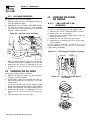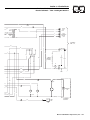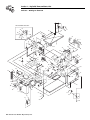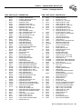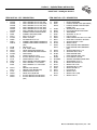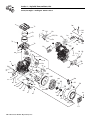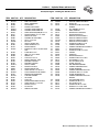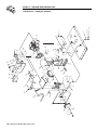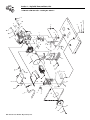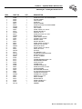
1
Installation and Owner’s Manual Air-cooled Automatic Standby Generators Models: 04758-1 (6 kW NG, 7 kW LP) 04759-1 (12 kW NG, 12 kW LP) 04760-1 (13 kW NG, 15 kW LP) GENERAC R POWER SYSTEMS, INC. R *This manual should remain with the unit.* ! Not intended for use as Primary Power in place of utility or in life-support applications. DANGER DEADLY EXHAUST FUMES. OUTDOOR INSTALLATION ONLY!! ! INTRODUCTION Thank you for purchasing this model by Generac Power Systems Inc.. This model is a compact, high performance, air-cooled, engine-driven generator designed to automatically supply electrical power to operate critical loads during a utility power failure. This unit is factory installed in an all-weather, metal enclosure that is intended exclusively for outdoor installation. This generator will operate using either vapor withdrawn liquid propane (LP) or natural gas (NG). This unit meets the 1998 and later California emissions regulations. To ensure that the engine continues to meet these regulations, refer to the following information and instructions in this owner’s manual. ENGINE EMISSION COMPLIANCE PERIOD For nonhandheld engines: The Emissions Compliance Period referred to on the Emissions Compliance label indicates the number of operating hours for which the engine has been shown to meet federal emission requirements. For engines less than 225 cc displacement, Category C = 125 hours, B = 250 hours, and A = 500 hours. For engines 225 cc or more, Category C = 250 hours, B = 500 hours, and A = 1000 hours. READ THIS MANUAL THOROUGHLY If any portion of this manual is not understood, contact the nearest Generac Authorized Dealer for starting, operating and servicing procedures. Throughout this publication, and on tags and decals affixed to the generator, DANGER, WARNING, CAUTION and NOTE blocks are used to alert personnel to special instructions about a particular operation that may be hazardous if performed incorrectly or carelessly. Observe them carefully. Their definitions are as follows: DANGER After this heading, read instructions that, if not strictly complied with, will result in serious personal injury, including death, in addition to property damage. ! This symbol points out important safety information that, if not followed, could endanger personal safety and/or property of others. This symbol points out potential explosion hazard. This symbol points out potential fire hazard. This symbol points out potential electrical shock hazard. The operator is responsible for proper and safe use of the equipment. We strongly recommend that the operator read this Owner's Manual and thoroughly understand all instructions before using this equipment. We also strongly recommend instructing other users to properly start and operate the unit. This prepares them if they need to operate the equipment in an emergency. CONTENTS This manual contains pertinent owner’s information, including warranty, electrical diagrams, exploded views and lists of repair parts, for three different Guardian models: • 04758-1 – 6 kW NG, 7 kW LP, single-cylinder GH410 Engine • 04759-1 – 12 kW NG, 12 kW LP, V-twin GT-990 Engine • 04760-1 – 13 kW NG, 15 kW LP, V-twin GT-990 Engine OPERATION AND MAINTENANCE It is the operator's responsibility to perform all safety checks, to make sure that all maintenance for safe operation is performed promptly, and to have the equipment checked periodically by a Generac Authorized Dealer. Normal maintenance service and replacement of parts are the responsibility of the owner/operator and, as such, are not considered defects in materials or workmanship within the terms of the warranty. Individual operating habits and usage contribute to the need for maintenance service. Proper maintenance and care of the generator ensures a minimum number of problems and keep operating expenses at a minimum. See the Generac Authorized Dealer for service aids and accessories. HOW TO OBTAIN SERVICE After this heading, read instructions that, if not strictly complied with, may result in serious personal injury or property damage. After this heading, read instructions that, if not strictly complied with, could result in damage to equipment and/or property. NOTE: After this heading, read explanatory statements that require special emphasis. These safety warnings cannot eliminate the hazards that they indicate. Common sense and strict compliance with the special instructions while performing the service are essential to preventing accidents. Four commonly used safety symbols accompany the DANGER, WARNING and CAUTION blocks. The type of information each indicates follows: When the generator requires servicing or repairs, simply contact a Generac Authorized Dealer for assistance. Service technicians are factory-trained and are capable of handling all service needs. When contacting a Generac Authorized Dealer or the factory about parts and service, always supply the complete model number and serial number of the unit as given on its data decal, which is located on the generator. See Figure 1.1 or Figure 1.2 in Section 1.4 for decal location. Model No. ____________ Serial No. ______________ AUTHORIZED DEALER LOCATION To locate the GENERAC AUTHORIZED DEALER nearest you, please call this number: 1-800-333-1322 DEALER LOCATION INFORMATION CAN BE OBTAINED AT THIS NUMBER. Table of Contents Guardian Air-cooled 7 kW, 12 kW and 15 kW Generators Introduction ........................Inside Front Cover 3.2.2 “Off” Position ....................................14 Read This Manual Thoroughly ........................IFC Contents ..........................................................IFC Operation and Maintenance ............................IFC How to Obtain Service ....................................IFC Authorized Dealer Locator Number ....................IFC 3.2.3 “Manual” Position ............................14 3.3 Automatic Transfer Operation ....................14 3.4 Sequence of Automatic Operation................14 3.5 Manual Transfer Operation ........................15 3.5.1 Transfer to Generator Power Source......................................15 Safety Rules ........................................................2 Standards Index ..................................................3 3.5.2 Transfer Back to Utility Power Source......................................15 Section 1 – General Information ..................4 1.1 Unpacking/Inspection ....................................4 3.6 Setting the Exercise Timer ..........................16 1.2 Protection Systems ........................................4 3.7 Protection Systems ......................................16 1.3 System Set LED ............................................4 3.7.1 Low Oil Pressure Switch ..................16 1.4 The Generator ..............................................5 3.7.2 High Temperature Switch ................16 1.5 Specifications ................................................6 3.7.3 Overcrank ........................................16 1.5.1 Generator ..........................................6 3.7.4 Overspeed ........................................16 1.5.2 Engine ................................................6 Section 4 – Maintenance ..............................17 1.6 Fuel Requirements and Recommendations....7 4.1 Fuse ............................................................17 1.7 Fuel Consumption ........................................7 4.2 Checking the Engine Oil Level ....................17 1.8 Reconfiguring the Fuel System ......................7 4.3 Changing the Engine Oil ..............................17 1.9 1.8.1 7 kW, 410CC ......................................7 4.3.1 Engine Oil Recommendations ..........17 1.8.2 12 kW and 15 kW, 990cc Engines ......7 4.3.2 Oil Change Procedure ......................18 Location ........................................................8 4.4 Changing the Oil Filter ................................18 1.9.1 Generator ..........................................8 4.5 Changing the Engine Air Cleaner ................18 1.9.2 Transfer Switch ..................................8 4.5.1 7 kW, 12 kW and 15 kW Generators........................................18 1.10 Battery Installation ........................................9 1.11 The Battery....................................................9 4.6 Section 2 – Post Installation Start-up and Adjustments ......................10 4.7 Battery Maintenance ....................................19 4.8 Adjusting Valve Clearance ............................20 2.1 2.2 Before Initial Start-up ..................................10 Check Transfer Switch Operation................10 4.9 Cooling System ............................................20 2.3 Electrical Checks ........................................10 4.11 Corrosion Protection ..................................21 2.4 Generator Tests Under Load ......................11 4.12 Out of Service Procedure ............................21 2.5 Checking Automatic Operation ....................11 4.12.1 Removal From Service ......................21 2.6 Adjusting the Regulator (Natural Gas Only) ..12 4.12.2 Return to Service..............................21 2.7 Engine Governor Adjustment ......................12 4.13 Service Schedule ........................................22 2.7.1 7 kW Units ......................................12 Section 5 – Troubleshooting ........................23 2.7.2 12 kW and 15 kW Units ..................13 5.1 2.7.3 Additional Corrosion Protection ......13 Section 6 – Electrical Data ............................24 Section 7 – Exploded Views and Parts Lists....................................32 Section 8 – Mounting Dimensions..............50 Section 9 – Notes ............................................51 Section 10 – Warranty ....................................52 2.8 Voltage Regulator Adjustment ......................13 Section 3 – Operation ....................................13 3.1 Break-in Procedure......................................13 3.2 Using the Auto/Off/Manual Switch ..............14 3.2.1 “Auto” Position ..................................14 Spark Plug(s) ..............................................19 4.10 Attention After Submersion ........................21 Troubleshooting Guide ................................23 Generac® Power Systems, Inc. 1 IMPORTANT SAFETY INSTRUCTIONS Guardian Air-cooled 7 kW, 12 kW and 15 kW Generators SAVE THESE INSTRUCTIONS – The manufacturer suggests that these rules for safe operation be copied and posted near the unit’s installation site. Safety should be stressed to all operators and potential operators of this equipment. ! ! WARNING: ! GENERAL HAZARDS ! ! The engine exhaust from this product contains chemicals known to the state of California to cause cancer, birth defects or other reproductive harm. ! WARNING: ! This product contains or emits chemicals known to the state of California to cause cancer, birth defects or other reproductive harm. Study these SAFETY RULES carefully before installing, operating or servicing this equipment. Become familiar with this Owner’s Manual and with the unit. The generator can operate safely, efficiently and reliably only if it is properly installed, operated and maintained. Many accidents are caused by failing to follow simple and fundamental rules or precautions. Generac cannot possibly anticipate every possible circumstance that might involve a hazard. The warnings in this manual, and on tags and decals affixed to the unit are, therefore, not all-inclusive. If using a procedure, work method or operating technique Generac does not specifically recommend, ensure that it is safe for others. Also make sure the procedure, work method or operating technique chosen does not render the generator unsafe. DANGER ! Despite the safe design of this generator, operating this equipment imprudently, neglecting its maintenance or being careless can cause possible injury or death. Permit only responsible and capable persons to operate or maintain this equipment. Potentially lethal voltages are generated by these machines. Ensure all steps are taken to render the machine safe before attempting to work on the generator. ! 2 Parts of the generator are rotating and/or hot during operation. Exercise care near running generators. Generac® Power Systems, Inc. ! • For safety reasons, Generac recommends that the installation, initial start-up and maintenance of this equipment is carried out by a Generac Authorized Dealer. • The engine exhaust fumes contain carbon monoxide, which can be DEADLY. This dangerous gas, if breathed in sufficient concentrations, can cause unconsciousness or even death. This exhaust system must be installed properly, in strict compliance with applicable codes and standards. Following installation, do nothing that might render the system unsafe or in noncompliance with such codes and standards. • Keep hands, feet, clothing, etc., away from drive belts, fans, and other moving or hot parts. Never remove any drive belt or fan guard while the unit is operating. • Adequate, unobstructed flow of cooling and ventilating air is critical to correct generator operation. Do not alter the installation or permit even partial blockage of ventilation provisions, as this can seriously affect safe operation of the generator. The generator MUST be installed outdoors. • When working on this equipment, remain alert at all times. Never work on the equipment when physically or mentally fatigued. • Inspect the generator regularly, and contact the nearest Generac Authorized Dealer for parts needing repair or replacement. • Before performing any maintenance on the generator, disconnect its battery cables to prevent accidental start up. Disconnect the cable from the battery post indicated by a NEGATIVE, NEG or (–) first. Reconnect that cable last. • Never use the generator or any of its parts as a step. Stepping on the unit can stress and break parts, and may result in dangerous operating conditions from leaking exhaust gases, fuel leakage, oil leakage, etc. IMPORTANT SAFETY INSTRUCTIONS Guardian Air-cooled 7 kW, 12 kW and 15 kW Generators ELECTRICAL HAZARDS • All generators covered by this manual produce dangerous electrical voltages and can cause fatal electrical shock. Utility power delivers extremely high and dangerous voltages to the transfer switch as does the standby generator when it is in operation. Avoid contact with bare wires, terminals, connections, etc., while the unit is running. Ensure all appropriate covers, guards and barriers are in place before operating the generator. If work must be done around an operating unit, stand on an insulated, dry surface to reduce shock hazard. • Do not handle any kind of electrical device while standing in water, while barefoot, or while hands or feet are wet. DANGEROUS ELECTRICAL SHOCK MAY RESULT. • The National Electrical Code (NEC) requires the frame and external electrically conductive parts of the generator to be connected to an approved earth ground. Local electrical codes also may require proper grounding of the generator electrical system. • After installing this home standby electrical system, the generator may crank and start at any time without warning. When this occurs, load circuits are transferred to the STANDBY (generator) power source. To prevent possible injury if such a start and transfer occur, always set the generator’s AUTO/OFF/MANUAL switch to its OFF position before working on equipment and remove the 5A and 15A fuses from the generator control panel. • In case of accident caused by electric shock, immediately shut down the source of electrical power. If this is not possible, attempt to free the victim from the live conductor. AVOID DIRECT CONTACT WITH THE VICTIM. Use a nonconducting implement, such as a rope or board, to free the victim from the live conductor. If the victim is unconscious, apply first aid and get immediate medical help. • Never wear jewelry when working on this equipment. Jewelry can conduct electricity resulting in electric shock, or may get caught in moving components causing injury. FIRE HAZARDS • For fire safety, the generator must be installed and maintained properly. Installation always must comply with applicable codes, standards, laws and regulations. Adhere strictly to local, state and national electrical and building codes. Comply with regulations the Occupational Safety and Health Administration (OSHA) has established. Also, ensure that the generator is installed in accordance with the manufacturer’s instructions and recommendations. Following proper installation, do nothing that might alter a safe installation and render the unit in noncompliance with the aforementioned codes, standards, laws and regulations. • Keep a fire extinguisher near the generator at all times. Extinguishers rated “ABC” by the National Fire Protection Association are appropriate for use on the standby electric system. Keep the extinguisher properly charged and be familiar with its use. If there are any questions pertaining to fire extinguishers, consult the local fire department. EXPLOSION HAZARDS • Do not smoke around the generator. Wipe up any fuel or oil spills immediately. Ensure that no combustible materials are left in the generator compartment, or on or near the generator, as FIRE or EXPLOSION may result. Keep the area surrounding the generator clean and free from debris. • Gaseous fluids such as natural gas and liquid propane (LP) gas are extremely EXPLOSIVE. Install the fuel supply system according to applicable fuel-gas codes. Before placing the home standby electric system into service, fuel system lines must be properly purged and leak tested according to applicable code. After installation, inspect the fuel system periodically for leaks. No leakage is permitted. STANDARDS INDEX In the absence of pertinent standards, codes, regulations and laws, the published information listed below may be used as installation guide for this equipment. 1. NFPA No. 37, STATIONARY COMBUSTION ENGINES AND GAS TURBINES, available from the National Fire Protection Association, 470 Atlantic Avenue, Boston, MA 02210. 2. NFPA No. 76A, ESSENTIAL ELECTRICAL SYSTEMS FOR HEALTH CARE FACILITIES, available same as Item 1. 3. NFPA No. 54, NATIONAL FUEL GAS CODE, available same as Item 1. 4. NFPA No. 58, AMERICAN NATIONAL STANDARD FOR STORAGE AND HANDLING OF LIQUEFIED PETROLEUM GAS, available same as Item 1. 5. NFPA No. 70, NFPA HANDBOOK OF NATIONAL ELECTRIC CODE, available same as Item 1. 6. Article X, NATIONAL BUILDING CODE, available from the American Insurance Association, 85 John Street, New York, N.Y. 10038. 7. AGRICULTURAL WIRING HANDBOOK, available from the Food and Energy Council, 909 University Avenue, Columbia, MO 65201. 8. ASAE EP-3634, INSTALLATION AND MAINTENANCE OF FARM STANDBY ELECTRICAL SYSTEMS, available from the American Society of Agricultural Engineers, 2950 Niles Road, St. Joseph, MI 49085. 9. NFPA No. 30, FLAMMABLE AND COMBUSTIBLE LIQUIDS CODE, available same as Item 1. Generac® Power Systems, Inc. 3 Section 1 — General Information Guardian Air-cooled 7 kW, 12 kW and 15 kW Generators DANGER ! 1.1 Only qualified electricians or contractors should attempt such installations, which must comply strictly with applicable codes, standards and regulations. UNPACKING/INSPECTION After unpacking, carefully inspect the contents for damage. • This standby generator set has been factory supplied with a weather protective enclosure that is intended for outdoor installation only. 1.2 PROTECTION SYSTEMS Unlike an automobile engine, the generator may have to run for long periods of time with no operator present to monitor engine conditions. For that reason, the engine is equipped with the following systems that protect it against potentially damaging conditions: 1. Low Oil Pressure Sensor 3. Overcrank 2. High Temperature Sensor 4. Overspeed There are LED readouts on the control panel to indicate that one of these faults has occurred. There is also a “System Set” LED that is described below. 1.3 SYSTEM SET LED The “System Set” LED is lit when all of the following conditions are true: If this generator is used to power electrical load circuits normally powered by a utility power source, it is required by code to install a transfer switch. The transfer switch must effectively isolate the electrical system from the utility distribution system when the generator is operating (NEC 700, 701 and 702). Failure to isolate an electrical system by such means will result in damage to the generator and also may result in injury or death to utility power workers due to backfeed of electrical energy. If any loss or damage is noted at time of delivery, have the person(s) making the delivery note all damage on the freight bill or affix his or her signature under the consignor's memo of loss or damage. If a loss or damage is noted after delivery, separate the damaged materials and contact the carrier for claim procedures. “Concealed damage” is understood to mean damage to the contents of a package that is not in evidence at the time of delivery, but is discovered later. 4 Generac® Power Systems, Inc. 1. The AUTO/OFF/MANUAL switch is set to the AUTO position. 2. The utility voltage being supplied to the unit is being sensed by the Control PCB. If the utility sense voltage is not connected to the unit or if it is below 168 volts AC, then the system set light will flash rapidly. This indicates that if the AUTO/OFF/MANUAL switch is placed in the Auto position , the generator will start. 3. The “Not In Auto” dip switch is set to the OFF position on the control board. 4. No alarms are present, for example, low oil pressure, high temperature, etc. Section 1 — General Information Guardian Air-cooled 7 kW, 12 kW and 15 kW Generators 1.4 THE GENERATOR Figure 1.1 – 7 kW, Single Cylinder GH-410 Engine Oil Check/Fill Data Decal Control Panel Exhaust Enclosure Air Filter Fuel Regulator Fuel Inlet Oil Filter Battery Compartment Figure 1.2 – 12 kW/15 kW, V-twin GT-990 Engine Oil Dipstick Data Decal Air Filter Exhaust Enclosure Control Panel Fuel Regulator Fuel Inlet Oil Filter Battery Compartment Generac® Power Systems, Inc. 5 Section 1 — General Information Guardian Air-cooled 7 kW, 12 kW and 15 kW Generators 1.5 SPECIFICATIONS 1.5.1 GENERATOR Rated Max. Continuous Power Capacity (Watts*) Rated Voltage Rated Max. Continuous Load Current (Amps) 120 Volts + 240 Volts Main Line Circuit Breaker Phase Number of Rotor Poles Rated AC Frequency Power Factor Recommended Air Filter Battery Requirement Weight Output Sound Level @ 23 ft (7m) at full load Normal Operating Range Model 04758 6,000 NG/7,000 LP 120/240 Model 04759 12,000 NG/12,000 LP 120/240 Model 04760 13,000 NG/15,000 LP† 120/240 50.0 NG/58.3 LP 100.0 NG/100.0 LP 108.3 NG/125.0 LP 25.0 NG/29.2 LP 50.0 NG/50.0 LP 54.2 NG/62.5 LP 30 Amp 50 Amp 70 Amp 1 1 1 2 2 2 60 Hz 60 Hz 60 Hz 1 1 1 Generac Part # C8127 Generac Part # C8127 Generac Part # C8127 Group 26/26R Group 26/26R Group 26/26R 12 Volts and 12 Volts and 12 Volts and 350 Cold-cranking 550 Cold-cranking 550 Cold-cranking Amperes Minimum Amperes Minimum Amperes Minimum 452 Pounds 470 Pounds 487 Pounds 68 db (A) 70.5db (A) 71.5 db (A) -20°F (-28.8°C) to 104°F (40°C) * Maximum wattage and current are subject to and limited by such factors as fuel Btu content, ambient temperature, altitude, engine power and condition, etc. Maximum power decreases about 3.5 percent for each 1,000 feet above sea level; and also will decrease about 1 percent for each 6° C (10° F) above 16° C (60° F). + Total current in TWO separate curcuits. Current in each curcuit must not exceed the value stated for 240V. 1.5.2 ENGINE Type of Engine Number of Cylinders Rated Horsepower Displacement Cylinder Block Valve Arrangement Ignition System Recommended Spark Plug Spark Plug Gap Compression Ratio Starter Oil Capacity Including Filter Recommended Oil Filter Recommended Air Filter Operating RPM 6 Generac® Power Systems, Inc. Model 04758 Model 04759 Model 04760 GH-410 GT-990 GT-990 1 2 2 14.5 @ 3,600 rpm 30 @ 3,600 rpm 30 @ 3,600 rpm 410cc 992cc 992cc Aluminum w/Cast Aluminum w/Cast Aluminum w/Cast Iron Sleeve Iron Sleeve Iron Sleeve Overhead Valves Overhead Valves Overhead Valves Solid-state w/Magneto Solid-state w/Magneto Solid-state w/Magneto RC12YC RC12YC RC12YC 0.76 mm (0.030 inch) 0.508 mm (0.020 inch) 0.508 mm (0.020 inch) 8.6:1 9.5:1 9.5:1 12 Vdc 12 Vdc 12Vdc Approx. 1.5 Qts Approx. 1.7 Qts Approx. 1.7 Qts Generac Part # 70185 Generac Part # 70185 Generac Part # 70185 Generac Part # 0C8127 Generac Part # 0C8127 Generac Part # 0C8127 3,600 3,600 3,600 Section 1 — General Information Guardian Air-cooled 7 kW, 12 kW and 15 kW Generators 1.6 FUEL REQUIREMENTS AND RECOMMENDATIONS With LP gas, use only the vapor withdrawal system. This type of system uses the vapors formed above the liquid fuel in the storage tank. The engine has been fitted with a fuel carburetion system that meets the specifications of the 1997 California Air Resources Board for tamper-proof dual fuel systems. The unit will run on natural gas or LP gas, but it has been factory set to run on natural gas. Should the primary fuel need to be changed to LP gas, the fuel system needs to be reconfigured. See Section 1.8 for instructions on reconfiguration of the fuel system. Recommended fuels should have a Btu content of at least 1,000 BTU’s per cubic foot for natural gas; or at least 2,520 BTU’s per cubic foot for LP gas. Ask the fuel supplier for the BTU content of the fuel. Fuel pressure for both natural gas and liquid propane set ups should be 11 inches to 14 inches of water column (0.6 psi) at all load ranges. 3. Disconnect wire #0 and wire #14 from the gas solenoid located on the top of the demand regulator. 4. Remove the demand regulator by rotating counterclockwise. 5. Remove the brass hose fitting from the outlet port of the demand regulator. 6. Remove the brass metering jet (loosen counterclockwise) from the housing port of the demand regulator located on the side of the regulator. 7. Install new LP metering jet (tighten clockwise) in the outlet port of the demand regulator. 8. Refit the brass hose fittings to the outlet port of the demand regulator. 9. Reverse procedure steps 1-4 to reinstall demand regulator. 10. Reverse the procedure to convert back to natural gas. Figure 1.3 – Demand Regulator FUEL HOSE BRASS HOSE FITTING FUEL HOSE BRASS HOSE FITTING NOTE: OUTLET PORT A separate gas line and regulator may be needed to assure proper gas pressure (11-14”) to the generator. Low gas pressure can cause hard starting and could affect engine durability. 1.7 FUEL CONSUMPTION Model # 04758 04759 04760 Nat. Gas (*) 1/2 Load Full Load 74 114 148.5 105 185 240 LP Vapor (**) 1/2 Load Full Load 0.91/33 1.34/48.9 1.73/63.2 1.21/44.1 2.17/79.0 2.80/102.3 *Natural gas is in cubic feet per hour. **LP is in gallons per hour/cubic feet per hour. DANGER Gaseous fuels such as natural gas and liquid propane (LP) gas are highly explosive. Even the slightest spark can ignite such fuels and cause an explosion. No leakage of fuel is permitted. Natural gas, which is lighter than air, tends to collect in high areas. LP gas is heavier than air and tends to settle in low areas. 1.8 FUEL JET REGULATOR HOUSING PORT RECONFIGURING THE FUEL SYSTEM ◆ 1.8.1 7 KW, 410CC To reconfigure the fuel system from NG to LP, follow these steps: 1. Turn the main gas supply off. 2. Remove the carburetor fuel hose from the outlet port of the demand regulator (Figure 1.3). NG FUEL SYSTEM LP FUEL SYSTEM NOTE: The natural gas adjustment screw is preset during installation and should not need any further adjustment. ◆ 1.8.2 12KW AND 15KW, 990CC ENGINES To reconfigure the fuel system from NG to LP, follow these steps: NOTE: The primary regulator for the propane supply is NOT INCLUDED with the generator. A fuel pressure of 11 to 14 inches of water column (0.6 psi) to the fuel inlet of the generator MUST BE SUPPLIED. 1. Turn OFF the main gas supply. 2. Remove the engine air in baffle located on the left hand side of the battery compartment. Two M6 screws are located on top of the baffle and two M6 screws are located on the inside of the baffle towards the back. Generac® Power Systems, Inc. 7 Section 1 — General Information Guardian Air-cooled 7 kW, 12 kW and 15 kW Generators 3. Remove the small hose clamp and hose from the fuel regulator. It may be necessary to pry the hose off of the brass fitting using a screw driver to gently lift up the hose edge. 4. Remove the brass hose fitting screwed into the fuel regulator. 5. Locate and identify the brass idle jet. This will be located in the fuel regulator casting facing the front of the unit. 6. Remove the idle jet from its holding location. 7. Place the idle jet, thread side first, into the threaded hole originally occupied by the brass hose fitting. 8. Using a short No. 2 Phillips screw driver, thread the idle jet into the regulator casting. DO NOT OVER TIGHTEN. 9. Apply thread sealant to the threads of the hose fitting and replace it into the regulator body. 10. Re-attach the small hose and hose clamp and tighten as necessary. 11. Replace the engine air in baffle using the four M6 screws. 12. Identify both brass adjustment screws on the regulator. NOTE: One adjustment screw can be accessed from the front of the unit and the second can be accessed from the back of the unit enclosure by removing the plastic hole plug. 13. To adjust the system to run on LP fuel, turn the adjuster screw that can be accessed from inside the front of the unit, ¼ TURN CLOCKWISE. This should now set the system for maximum power and best performance. 14. It may be necessary to make minor adjustments to the preset adjustment screw settings to achieve maximum power. If experiencing problems with the unit producing maximum power, follow the procedure in Section 2.6 (Adjusting the Fuel Regulator). Figure 1.4 - Demand Regulator OUTLET PORTS FUEL HOSE BRASS HOSE FITTING IDLE CIRCUIT PORT O U T 1 PRESSURE TAP 1/8 NPT BRASS HOSE FITTING SMALL FUEL JET REGULATOR HOUSING PORT ADJUSTER SCREWS 8 Generac® Power Systems, Inc. 1.9 LOCATION ◆ 1.9.1 GENERATOR Install the generator set, in its protective enclosure, outdoors, where adequate cooling and ventilating air is always available. Consider these factors: • Install the unit where air inlet and outlet openings will not become obstructed by leaves, grass, snow, etc. If prevailing winds will cause blowing or drifting, consider using a windbreak to protect the unit. • Install the generator on high ground where water levels will not rise and endanger it. • Allow sufficient room on all sides of the generator for maintenance and servicing. A good rule is to allow three feet of space on all sides. • Where strong prevailing winds blow from one direction, face the generator air inlet openings to the prevailing winds. • Install the generator as close as possible to the fuel supply, to reduce the length of piping. • Install the generator as close as possible to the transfer switch. HOWEVER, REMEMBER THAT LAWS OR CODES MAY REGULATE THE DISTANCE. ◆ 1.9.2 TRANSFER SWITCH 1.9.2.1 7 kW, 12 kW and 15 kW Units Transfer switches for use with these generators are sold separately and can be purchased from Generac Authorized Dealers. • Install the transfer switch on a firm, sturdy supporting structure. • To prevent switch distortion, level the switch if necessary. This can be done by placing washers between the switch enclosure and mounting surface. • Never install the switch where water or any corrosive substance might drip onto the enclosure. • Protect the switch at all times against excessive moisture, dust, dirt, lint, construction grit and corrosive vapors. • Failure to utilize a Generac/Guardian transfer switch with this generator will void the warranty. Transfer switches available for these generators are: • Model NEMA • Model NEMA 004678-0 — 100 Amp, 2 Pole, 250 Volt 1 (indoor rated) or 004635-0 — 200 Amp, 2 Pole, 250 Volt 3R (outdoor rated) Section 1 — General Information Guardian Air-cooled 7 kW, 12 kW and 15 kW Generators NOTE: 1.10 BATTERY INSTALLATION Fill the battery with the proper electrolyte fluid if necessary and have the battery fully charged before installing it. Before installing and connecting the battery, complete the following steps: 1. Set the generator's AUTO/OFF/MANUAL switch to OFF. 2. Turn off utility power supply to the transfer switch. 3. Remove the 5 amp and 15 amp fuses from the generator control panel. If the AUTO/OFF/MANUAL switch is not set to its OFF position, the generator can crank and start as soon as the battery cables are connected. If the utility power supply is not turned off, sparking can occur at the battery posts and cause an explosion. Battery cables were factory connected at the generator (Figure 1.5). Connect cables to battery posts as follows: 4. Connect the red battery cable (from starter contactor) to the battery post indicated by a positive, POS or (+). 5. Connect the black battery cable (from frame ground) to the battery post indicated by a negative, NEG or (—). 6. Replace the 5 amp and 15 amp fuses in the generator control panel. NOTE: Damage will result if battery connections are made in reverse. Figure 1.5 – Battery Cable Connections The generator is equipped with a battery trickle charger that is active when the unit is set up for automatic operation. With the battery installed and utility power source voltage available to the transfer switch, the battery receives a trickle charge while the engine is not running, to prevent self-discharge. The trickle charger is designed to help extend the life of the battery by maintaining the battery when the unit is not running. The trickle charge feature cannot be used to recharge a discharged battery. 1.11 THE BATTERY Servicing of the battery is to be performed or supervised by personnel knowledgeable of batteries and the required precautions. Keep unauthorized personnel away from batteries. When replacing the battery, use the following type of battery: Group 26/26R 12-volt battery with a rating of 350 cold-cranking amps minimum for 7 kW; 550 cold-cranking amps minimum for 12 and 15 kW at -18º C (0º F) minimum. When using a maintenancefree battery, it is not necessary to check the specific gravity or electrolyte level. Have these procedures performed at the intervals specified in the “Service Schedule.” A negative ground system is used. Battery connections are shown on the wiring diagrams. Make sure the battery is correctly connected and terminals are tight. Observe battery polarity when connecting the battery to the generator set. DANGER Do not dispose of the battery in a fire. The battery is capable of exploding. A battery presents a risk of electrical shock and high short circuit current. The following precautions are to be observed when working on batteries: • Remove watches, rings or other metal objects; • Use tools with insulated handles; • Wear rubber gloves and boots; • Do not lay tools or metal parts on top of the battery; and • Disconnect charging source prior to connecting or disconnecting battery terminals. ! Do not open or mutilate the battery. Released electrolyte has been known to be harmful to the skin and eyes, and to be toxic. ! The electrolyte is a dilute sulfuric acid that is harmful to the skin and eyes. It is electrically conductive and corrosive. Generac® Power Systems, Inc. 9 Section 2 — Post Installation Start-up and Adjustments Guardian Air-cooled 7 kW, 12 kW and 15 kW Generators The following procedures are to be observed: • Wear full eye protection and protective clothing; • Where electrolyte contacts the skin, wash it off immediately with water; • Where electrolyte contacts the eyes, immediately flush thoroughly with water and seek medical attention; and • Spilled electrolyte is to be washed down with an acid neutralizing agent. A common practice is to use a solution of 1 pound (500 grams) bicarbonate of soda to 1 gallon (4 liters) or water. The bicarbonate of soda solution is to be added until the evidence of reaction (foaming) has ceased. The resulting liquid is to be flushed with water and the area dried. Lead-acid batteries present a risk of fire because they generate hydrogen gas. The following procedures are to be followed: • DO NOT SMOKE when near the battery; • DO NOT cause flame or spark in battery area; and • Discharge static electricity from body before touching the battery by first touching a grounded metal surface. ! Be sure the AUTO/OFF/MANUAL switch is set to the OFF position before connecting the battery cables. If the switch is set to AUTO or MANUAL, the generator can crank and start as soon as the battery cables are connected. Be sure the utility power supply is turned off, or sparking may occur at the battery posts as the cables are attached and cause an explosion. 2.1 1. Set the generator’s main circuit breaker to its OFF (or open) position. 2. Set the generator's AUTO/OFF/MANUAL switch to the OFF position. 3. Turn OFF the utility power supply to the transfer switch using the means provided (such as the utility main line circuit breaker). 4. Check the engine crankcase oil level and, if necessary, fill to the dipstick FULL mark with the recommended oil. Do not fill above the FULL mark. 5. Check the fuel supply. Gaseous fuel lines must have been properly purged and leak tested in accordance with applicable fuel-gas codes. All fuel shutoff valves in the fuel supply lines must be open. Never operate the engine with the oil level below the “Add” mark on the dipstick. Doing this could damage the engine. 10 Generac® Power Systems, Inc. CHECK TRANSFER SWITCH OPERATION Refer to Section 3.5, of the owner’s manual for manual operation procedures. DANGER Do not attempt manual transfer switch operation until all power voltage supplies to the transfer switch have been positively turned off. Failure to turn off all power voltage supplies will result in extremely hazardous and possibly fatal electrical shock. 2.3 ELECTRICAL CHECKS Complete electrical checks as follows: 1. Turn on the utility power supply to the transfer switch using the means provided (such as a utility main line circuit breaker). DANGER 2. 3. BEFORE INITIAL START-UP Before starting, complete the following: ! 2.2 4. 5. 6. 7. The transfer switch is now electrically “hot.” Contact with “hot” parts will result in extremely hazardous and possibly fatal electrical shock. Proceed with caution. Use an accurate AC voltmeter to check utility power source voltage across terminals N1 and N2. Nominal line-to-line voltage should be 240 volts AC. Check utility power source voltage across terminals N1 and the transfer switch neutral lug; then across terminal N2 and neutral. Nominal line-toneutral voltage should be 120 volts AC. When certain that utility supply voltage is compatible with transfer switch and load circuit ratings, turn OFF the utility power supply to the transfer switch. Set the generator's main circuit breaker to its OFF (or open) position. Initial tests will be conducted at no-load condition. On the generator panel, set the AUTO/OFF/MANUAL switch to MANUAL. The engine should crank and start. Let the engine warm up for about five minutes to allow internal temperatures to stabilize. Then, set the generator’s main circuit breaker to its ON (or closed) position. DANGER Proceed with caution! Generator power voltage is now supplied to the transfer switch. Contact with live transfer switch parts will result in dangerous and possibly fatal electrical shock. Section 2 — Post Installation Start-up and Adjustments Guardian Air-cooled 7 kW, 12 kW and 15 kW Generators 8. Connect an accurate AC voltmeter and a frequency meter across transfer switch terminal lugs E1 and E2. Voltage should be 242-252 volts; frequency should read about 61-63 Hertz. 9. Connect the AC voltmeter test leads across terminal lug E1 and neutral; then across E2 and neutral. In both cases, voltage reading should be 121126 volts AC. 10. Set the generator’s main circuit breaker to its OFF (or open) position. Let the engine run at noload for a few minutes to stabilize internal engine generator temperatures. 11. Set the generator's AUTO/OFF/MANUAL switch to OFF. The engine should shut down. NOTE: It is important not to proceed until certain that generator AC voltage and frequency are correct and within the stated limits. Generally, if both AC frequency and voltage are high or low, the engine governor requires adjustment. If frequency is correct, but voltage is high or low, the generator’s voltage regulator requires adjustment. 2.4 GENERATOR TESTS UNDER LOAD To test the generator set with electrical loads applied, proceed as follows: 1. Set generator’s main circuit breaker to its OFF (or open) position. 2. Set the generator's AUTO/OFF/MANUAL switch to OFF. 3. Turn OFF the utility power supply to the transfer switch, using the means provided (such as a utility main line circuit breaker). 4. 5. 6. 7. Do not attempt manual transfer switch operation until all power voltage supplies to the transfer switch have been positively turned off. Failure to turn off all power voltage supplies will result in extremely hazardous and possibly fatal electrical shock. Manually set the transfer switch to the STANDBY position, i.e., load terminals connected to the generator's E1/E2 terminals. The transfer switch operating lever should be down. Set the generator's AUTO/OFF/MANUAL switch to MANUAL. The engine should crank and start immediately. Let the engine stabilize and warm up for a few minutes. Set the generator’s main circuit breaker to its ON (or closed) position. Loads are now powered by the standby generator. 8. Turn ON electrical loads. Apply an electrical load equal to the full rated wattage/amperage capacity of the installed generator. 9. Connect an accurate AC voltmeter and a frequency meter across terminal lugs E1 and E2. Voltage should be greater than 230 volts; frequency should be greater than 58 Hertz. 10. Let the generator run at full rated load for 20-30 minutes. Listen for unusual noises, vibration or other indications of abnormal operation. Check for oil leaks, evidence of overheating, etc. 11. When testing under load is complete, turn OFF electrical loads. 12. Set the generator's main circuit breakers to their OFF (or open) positions. 13. Let the engine run at no-load for a few minutes. 14. Set the AUTO/OFF/MANUAL switch to OFF. The engine should shut down. 2.5 CHECKING AUTOMATIC OPERATION To check the system for proper automatic operation, proceed as follows: 1. Set the generator’s main circuit breaker to it’s OFF (or open) position. 2. Check that the AUTO/OFF/MANUAL switch is set to OFF. 3. Turn OFF the utility power supply to the transfer switch using the means provided (such as a utility main line circuit breaker). 4. Manually set the transfer switch to the UTILITY position, i.e., load terminals connected to the utility power source side. 5. Turn ON the utility power supply to the transfer switch, using the means provided (such as a utility main line circuit breaker). 6. Set the AUTO/OFF/MANUAL switch to AUTO. Then set the generator’s main circuit breaker to its ON (or closed) position. The system is now ready for automatic operation. 7. Turn OFF the utility power supply to the transfer switch. With the AUTO/OFF/MANUAL switch at AUTO, the engine should crank and start when the utility source power is turned OFF. After starting, the transfer switch should connect load circuits to the standby side. Let the system go through its entire automatic sequence of operation. With the generator running and loads powered by generator AC output, turn ON the utility power supply to the transfer switch. The following should occur: • After about six seconds, the switch should transfer loads back to the utility power source. • About one minute after retransfer, the engine should shut down. Generac® Power Systems, Inc. 11 Section 3 — Operation Guardian Air-cooled 7 kW, 12 kW and 15 kW Generators 2.6 ADJUSTING THE REGULATOR (NATURAL GAS ONLY) Figure 2.2 — Placement of Regulator Although the generator has been factory set to provide maximum power, it may be necessary in some areas to adjust this setting. Because natural gas has different BTU or power content across the country the engine may not perform as designed. If experiencing engine problems at high or full load conditions follow these steps. It will require a frequency meter to perform this procedure. 1. Turn off utility power to the main distribution panel in the house. This can be done by switching the service main breaker to the off or open position. 2. Allow the generator to start before loading the generator. Confirm the no-load frequency with the roof open and door off is set at 63-63.5 Hz. Transfer load to emergency circuits. 3. Turn on appliances, lights, pumps, etc., that are on the emergency circuits in an attempt to fully load the generator. Be cautious not to overload the generator. Use the following chart as a guide: Unit 120 Volts 240 Volts 7 kW 50.0 amps 25.0 amps 12 kW 100.0 amps 50.0 amps 15 kW 108.3 amps 54.2 amps 4. When full load has been achieved. Connect a frequency meter to the output lugs of the generator’s main line circuit breaker. 5. The fuel regulator is fitted with one (7 kW), or two (12 & 15 kW) adjustment screws. While watching the frequency meter, slowly turn the adjustment screw clockwise or counterclockwise one at a time until highest frequency is read on the meter. Only limited adjustment is available between the set pins. Under no circumstances should any of the pins be removed (Figures 2.1 and 2.2). Figure 2.1 — Dual Fuel Regulators 6 and 4107 kW 12, 13,990 and 15 kW Adjustment Screw (Both sides) Adjustment Screw (One Side Only) Set Pins 6. When the highest frequency is reached maximum power has been set. Then turn both adjustment screws 1/4 turn counterclockwise. Regulator is now set. 12 Generac® Power Systems, Inc. Adjustment Screw 7. Turn utility power to the main distribution panel back on. This can be done by switching the service main breaker to the on or closed position. Allow the generator to shut down. Do not make any unnecessary adjustments. Factory settings are correct for most applications. However, when making adjustments, be careful to avoid overspeeding the engine. If this procedure or equipment are not available, locate the nearest Generac Guardian Dealer and they can perform the adjustments. ! NOTE: A service fee may be charged for this adjustment. 2.7 ENGINE GOVERNOR ADJUSTMENT If both AC frequency and voltage are correspondingly high or low, adjust the engine governor as follows: ◆ 2.7.1 7 KW UNITS 1. Loosen the governor clamp bolt (Figure 2.3). 2. Hold the governor lever at its wide open throttle position, and rotate the governor shaft clockwise as far as it will go. Then, tighten the governor lever clamp bolt to 70 inch-pounds (8 N-m). 3. Start the generator; let it stabilize and warm up at no-load. 4. Connect a frequency meter across the generators AC output leads. 5. Turn the speed adjust nut to obtain a frequency reading of 63 Hz. 6. When frequency is correct at no load, check the AC voltage reading. If voltage is incorrect, the voltage regulator may require adjustment. Section 3 — Operation Guardian Air-cooled 7 kW, 12 kW and 15 kW Generators Figure 2.3 — Engine Governor Adjustment ◆ 2.7.3 ADDITIONAL CORROSION PROTECTION Periodically spray all engine linkage parts and brackets with corrosion inhibiting spray such as WD-40 or a comparable product. Idle Spring 2.8 Governor Shaft (Rotate Clockwise) VOLTAGE REGULATOR ADJUSTMENT With the frequency between 62-63.5 Hertz, slowly turn the slotted potentiometer (Figure 2.5) until line voltage reads 244-252 volts. NOTE: Remove the access panel on top of the control panel to adjust the voltage regulator. Governor Clamp Bolt ◆ 2.7.2 No Load Idle Adjustment Screw Figure 2.5 – Voltage Adjustment Potentiometer 12 KW AND 15 KW UNITS 1. Loosen governor clamp bolt (See Figure 2.3). 2. Completely remove the idle spring. 3. With governor arm at wide open throttle position, rotate governor shaft fully clockwise. Tighten clamp bolt to 84 inch-pounds. 4. Start unit and apply full load. Use full load speed adjust screw (Figure 2.4) to adjust frequency to 58 Hz. 5. Remove load, stop engine, loosen the idle adjust screw and reconnect the idle spring. 6. Using a hand, push the governor arm to the closed throttle position. Make sure the idle spring does not stretch at all. 7. Restart the unit. 8. Slowly turn the idle adjust screw to adjust the noload idle frequency to 63-63.5 Hz. 9. The governor is now set. Figure 2.4 — Full Load Speed Adjust Screw Full Load Speed Adjust Screw NOTE: The voltage regulator is housed above the generator's control panel. The regulator maintains a voltage in direct proportion to frequency. For example, at 62 Hertz, line-to-neutral voltage will be 124 volts. 3.1 BREAK-IN PROCEDURE Once the unit has been installed, with utility power connected to the transfer switch, and all electrical checks have been made, it is strongly recommended that the following “Break-in Procedure” be completed to ensure correct generator operation in the future. 1. Set the generator’s AUTO/OFF/MANUAL switch to AUTO. 2. Turn OFF the utility power supply to the transfer switch using the means provided (such as a utility main line circuit breaker). 3. The unit will start, and the transfer switch will transfer to standby. 4. Run the unit for one hour at 25 percent load. 5. Run the unit for one hour at 50 percent load. 6. Run the unit for one hour at 75 percent load. 7. Run the unit for one hour at 100 percent load. Generac® Power Systems, Inc. 13 Section 3 — Operation Guardian Air-cooled 7 kW, 12 kW and 15 kW Generators 8. Turn ON the utility power supply to the transfer switch, which will allow the transfer switch to transfer back to utility power. The unit will continue to run for one minute and then shut down. 9. Allow the unit to cool. 10. Drain the oil and remove the oil filter. Replace the oil filter according to Section 4.4, “Changing the Oil Filter”. Replace the oil with synthetic oil as recommended in Section 4.3, “Changing the Engine Oil”. 11. The generator is now ready for service. 3.2 USING THE AUTO/OFF/MANUAL SWITCH (FIGURE 3.1) 3.2.1 “AUTO” POSITION Selecting this switch position activates fully automatic system operation. It also permits starting and exercising the engine every seven days with the setting of the exercise timer (see Section 3.6). This position also is used for remote starting, when it is set up. 3.2.2 “OFF” POSITION This switch position shuts down the engine. This position also prevents automatic operation. 3.2.3 “MANUAL” POSITION Set the switch to MANUAL to crank and start the engine. Transfer to standby power will not occur unless there is a utility failure. Figure 3.1 – Generator Control Panel FUSE R Locat e y our near est d e a le r a t : R POWER SYSTEMS, INC. 5A AUTO OFF SYSTEM SET MAN. LOW OIL HIGH TEMP. FUSE OVER SPEED OVER CRANK 15A ! SET EXERCISE TIME F L A S H IN G G R E E N L E D = N O U T IL IT Y S E N S E 4 F L A S H IN G R E D L E D S = E X E R C IS E R N O T S E T With the switch set to AUTO, the engine may crank and start at any time without warning. Such automatic starting normally occurs when utility power source voltage drops below a preset level or during the normal exercise cycle. To prevent possible injury that might be caused by such sudden starts, always set the switch to OFF and remove both fuses before working on or around the generator or transfer switch. Then, place a “Do Not Operate” tag on the generator panel and on the transfer switch. 14 Generac® Power Systems, Inc. 3.3 AUTOMATIC TRANSFER OPERATION To select automatic operation, do the following: 1. Make sure the transfer switch main contacts are set to their “Utility” position, i.e., loads connected to the utility power source (Figure 3.2). 2. Be sure that normal utility power source voltage is available to transfer switch terminal lugs N1 and N2. 3. Set the generator’s AUTO/OFF/MANUAL switch to AUTO. 4. Set the generator’s main circuit breaker to its ON (or closed) position. With the preceding steps complete, the generator will start automatically when utility source voltage drops below a preset level. After the unit starts, loads are transferred to the standby power source. Refer to Section 3.4, “Sequence of Automatic Operation.” 3.4 SEQUENCE OF AUTOMATIC OPERATION The generator’s control panel houses a control logic circuit board. This board constantly monitors utility power source voltage. Should that voltage drop below a preset level, circuit board action will signal the engine to crank and start. After the engine starts, the circuit board signals the transfer switch to activate and connect load circuits to the standby power supply (load terminal lugs T1/T2 connect to terminal lugs E1/E2). Upon restoration of utility source voltage above a preset level, generator circuit board action signals the transfer switch to transfer loads back to that power supply. After retransfer, the engine is signalled to shut down. The actual sequence of operation is controlled by sensors and timers on a control logic circuit board, as follows: A. Utility Voltage Dropout Sensor • This sensor monitors utility source voltage. • If utility source voltage drops below about 70 percent of the nominal supply voltage, the sensor energizes a 15-second timer. • Once the timer has expired, the engine will crank and start. B. Engine Warm-up Time Delay • This mechanism lets the engine warm up for about 10 seconds before the load is transferred to a standby source. C.Standby Voltage Sensor • This sensor monitors generator AC output voltage. When the voltage has reached 50 percent of the nominal rated voltage, transfer to standby can occur. Section 3 — Operation Guardian Air-cooled 7 kW, 12 kW and 15 kW Generators D.Utility Voltage Pickup Sensor • This sensor monitors utility power supply voltage. When that voltage is restored to above 70 percent of the nominal source voltage, a retransfer time delay starts timing. E.Retransfer Time Delay • This timer runs for about 15 seconds. • At end of a 15-second delay, circuit board action de-energizes the transfer relay in the transfer switch. • Retransfer to utility power source then occurs. F. Engine Cool-down Timer • When the load is transferred back to utility power source, the engine cool-down timer starts timing. • The timer will run for about one minute, and the generator will then shut down. 3.5 MANUAL TRANSFER OPERATION 3.5.1 TRANSFER TO GENERATOR POWER SOURCE To start the generator and activate the transfer switch manually, proceed as follows: Figure 3.2 – Manual Transfer Switch Operation 3.5.2 TRANSFER BACK TO UTILITY POWER SOURCE When utility power has been restored, transfer back to that source and shut down the generator. This can be accomplished as follows: 1. Set the generator’s main circuit breaker to its OFF (or open) position. 2. Set the generator’s AUTO/OFF/MANUAL switch to OFF. 3. Turn OFF the utility power supply to the transfer switch using the means provided (such as a utility main line circuit breaker). 1. Set the generator’s main circuit breaker to its OFF (or open) position. 2. Let the engine run for a minute or two at no-load to stabilize the internal temperatures. 3. Set the generator’s AUTO/OFF/MANUAL switch to its OFF (or open) position. The engine should shut down. 4. Check that utility power supply to the transfer switch is turned OFF. DANGER DANGER 4. 5. 6. 7. Do not attempt to activate the transfer switch manually until all power voltage supplies to the switch have been positively turned off. Failure to turn off all power voltage supplies may result in extremely hazardous and possibly fatal electrical shock. Use the manual transfer handle inside the transfer switch to move the main contacts to their “Standby” position, i.e., loads connected to the standby power source (Figure 3.2). To crank and start the engine, set the AUTO/OFF/ MANUAL switch to MANUAL. Let the engine stabilize and warm up for a few minutes. Set the generator’s main circuit breaker to its ON (or closed) position. The standby power source now powers the loads. Do not attempt to activate the transfer switch manually until all power voltage supplies to the switch have been positively turned off. Failure to turn off all power voltage supplies may result in extremely hazardous and possibly fatal electrical shock. 5. Use the manual transfer handle inside the transfer switch to move the main contacts back to their “Utility” position, i.e., loads connected to the utility power source (Figure 3.2). 6. Turn ON the utility power supply to the transfer switch using the means provided. 7. Set the system to automatic operation as outlined in “Automatic Transfer Operation,” Section 3.3. Generac® Power Systems, Inc. 15 Section 3 — Operation Guardian Air-cooled 7 kW, 12 kW and 15 kW Generators 3.6 SETTING THE EXERCISE TIMER Figure 3.3 – Low Oil Pressure and High Temperature Switches The generator is equipped with an exercise timer. Once it is set, the generator will start and exercise once every seven days, on the day of the week and at the time of day the following sequence is completed. During this exercise period, the unit runs for approximately 12 minutes and then shuts down. Transfer of loads to the generator output does not occur during the exercise cycle. Low Oil Switch A switch on the control panel (see Figure 3.1) permits selection of the day and time for system exercise. To select the desired day and time of day, the following sequence must be performed at that time. 1. Verify that the AUTO/OFF/MANUAL switch is set to AUTO. 2. Hold down the set timer switch until the generator starts (approximately 10 seconds) and then release. 3. The generator will start and run for approximately 12 minutes and then shut down on its own. The exerciser will then be set to run at that time of day every week. NOTE: The exerciser will only work in the AUTO mode and will not work unless this procedure is performed. The exerciser will need to be reset every time the 12-volt battery is disconnected and then reconnected. The exerciser WILL NOT work if dip switch 2 (Remote Not Auto) on the controller printed circuit board is ON. 3.7 PROTECTION SYSTEMS 3.7.1 LOW OIL PRESSURE SWITCH This switch (Figure 3.3) has normally closed contacts that are held open by engine oil pressure during cranking and operating. Should oil pressure drop below the 8 psi range, switch contacts close, and the engine shuts down. The unit should not be restarted until oil is added, and the AUTO/OFF/MANUAL switch must be turned to OFF and then back to AUTO. 3.7.2 HIGH TEMPERATURE SWITCH This switch’s contacts (Figure 3.3) close if the temperature should exceed approximately 140º C (284º F), initiating an engine shutdown. The generator will automatically restart and the LED will reset once the temperature has returned to a safe operating level. 16 Generac® Power Systems, Inc. High Temp Switch Loos en Oil Drain Hose Oil Filter 3.7.3 OVERCRANK This feature prevents the generator from damaging itself when it continually attempts to start and another problem, such as no fuel supply, prevents it from starting. The unit will crank and rest for a preset time limit. Then, it will stop cranking, and the LED will light indicating an overcrank failure. The AUTO/OFF/MANUAL switch will need to be set to OFF and then back to AUTO to reset the generator control board. NOTE: If the fault is not repaired, the overcrank feature will continue to activate. 3.7.3.1 Approximate Crank Cycle Times • • • • • 15 seconds ON 7 seconds OFF 7 seconds ON 7 seconds OFF Repeat for 45 seconds Approximately 90 seconds total 3.7.4 OVERSPEED This feature protects the generator from damage by shutting it down if it happens to run faster than the preset limit. This protection also prevents the generator from supplying an output that could potentially damage appliances connected to the generator circuit. Contact the nearest Generac Authorized Dealer if this failure occurs. Section 4 — Maintenance Guardian Air-cooled 7 kW, 12 kW and 15 kW Generators 4.1 FUSE Figure 4.2 — Oil Dipstick and Fill, 7 kW The generator panel’s 15 amp fuse (Figure 4.1) protects the DC control circuit against overload. The fuse is wired in series with the battery output lead to the panel. If the fuse element has melted open, the engine cannot crank or start. Replace the fuse using only an identical 15-amp replacement. Oil Dipstick and Fill The generator panel’s 5 amp fuse protects the battery charge circuit against overload. If the fuse element has melted open, battery charging capability will not be possible. Replace the fuse using only an identical 5 amp replacement. To remove fuse, push cap down and rotate counterclockwise. Figure 4.1 – Generator Control Panel FUSE R Locat e y our near est Figure 4.3 — Oil Dipstick and Fill, 12 kW and 15 kW d e a le r a t : R POWER SYSTEMS, INC. 5A AUTO OFF Oil Dipstick SYSTEM SET MAN. LOW OIL HIGH TEMP. FUSE OVER SPEED OVER CRANK 15A 4.2 SET EXERCISE TIME F L A S H IN G G R E E N L E D = N O U T IL IT Y S E N S E 4 F L A S H IN G R E D L E D S = E X E R C IS E R N O T S E T Oil Fill CHECKING THE ENGINE OIL LEVEL For oil capacities, see “Specifications,” Section 1.5. For engine oil recommendations, see Section 4.3.1. To check the engine oil level, proceed as follows (Figure 4.2): 1. Start the generator by moving the Auto/ Off/Manual switch to the MANUAL position. Allow it to run for a short while and then shut it down by moving the switch to the OFF position. 2. Remove the dipstick and wipe it dry with a clean cloth. 3. Install the dipstick; then, remove it again. The oil level should be at the dipstick “Full” mark. If necessary, add oil to the “Full” mark only. DO NOT FILL ABOVE THE “FULL” MARK. 4.3 CHANGING THE ENGINE OIL 4.3.1 ENGINE OIL RECOMMENDATIONS Use oil of American Petroleum Institute (API) Service Class SG, SH or SJ. Use all season SAE 5W-30 Synthetic oil. Organic break-in oil is required before using synthetic oil. NOTE: Never operate the engine with the oil level ! below the “Add” mark on the dipstick. Doing this could damage the engine. 4. Install the dipstick. 5. Reset the AUTO/OFF/MANUAL switch to its original position. The unit is supplied with “break-in” oil. See the “Break-in Procedure,” Section 3.1, for the first required oil change. ! Any attempt to crank or start the engine before it has been properly serviced with the recommended oil may result in an engine failure. Generac® Power Systems, Inc. 17 Section 4 — Maintenance Guardian Air-cooled 7 kW, 12 kW and 15 kW Generators 4.3.2 OIL CHANGE PROCEDURE To change the oil, proceed as follows: 1. Run the engine until it is thoroughly warmed up then shut OFF the engine. 2. Immediately after the engine shuts OFF, pull the oil drain hose (Figure 4.4) free of its retaining clip. Remove the cap from the hose and drain the oil into a suitable container. Figure 4.4 – Oil Drain Hose and Filter Loos en Oil Drain Hose 4.5 CHANGING THE ENGINE AIR CLEANER 4.5.1 7 KW, 12 KW AND 15 KW GENERATORS See Figures 1.1 and 1.2, for the location of the air cleaner. Use the following procedure (Figure 4.6): 1. Turn the two screws counterclockwise to loosen. 2. Remove the cover and air filter. 3. Wipe away dust or debris from inside of the air box and around edges. 4. Install the new air cleaner into the air box. 5. Install the cover. Turn the two cover screws clockwise to tighten. See the “Service Schedule,” Section 4.13 for air cleaner maintenance. See Section 1.5.1 for air filter replacement part number. Figure 4.6 — 7 kW, Engine Air Cleaner Location Oil Filter Air Cleaner Fuel Regulator 3. After the oil has drained, replace the cap onto the end of the oil drain hose. Retain the hose in the clip. 4. Refill with the proper recommended oil (see Section 4.3.1). See Section 1.5.2 for oil capacities. 4.4 CHANGING THE OIL FILTER Change the engine oil filter as follows: 1. With the oil drained, remove the old oil filter by turning it counterclockwise. 2. Apply a light coating of clean engine oil to the gasket of the new filter. See Section 1.5.1 for recommended filter. 3. Screw the new filter on by hand until its gasket lightly contacts the oil filter adapter. Then, tighten the filter an additional 3/4 to one turn (Figure 4.4). 4. Refill with the proper recommended oil (see Section 4.3.1). See Section 1.5.2 for oil capacities. 5. Start the engine and check for leaks. Figure 4.7 — 12 kW and 15 kW Engine Air Cleaner Screw Cover Filter 18 Generac® Power Systems, Inc. Section 4 — Maintenance Guardian Air-cooled 7 kW, 12 kW and 15 kW Generators 4.6 SPARK PLUG(S) Reset the spark plug(s) gap or replace the spark plug(s) as necessary. See Section 4.13 for maintenance requirements. 1. Clean the area around the base of the spark plug(s) to keep dirt and debris out of the engine. Clean by scraping or washing using a wire brush and commercial solvent. Do not blast the spark plug(s) to clean. 2. Remove the spark plug(s) and check the condition. Replace the spark plug(s) if worn or if reuse is questionable. See Section 4.13 for recommended inspection. 3. Check the spark plug gap using a wire feeler gauge. Adjust the gap to 0.76 mm (0.030 inch) for 7 kW and 0.50 mm (0.020 inch) for 12/15 kW by carefully bending the ground electrode (Figure 4.8). Figure 4.8 – Setting the Spark Plug Gap • • • • Remove watches, rings or other metal objects; Use tools with insulated handles; Wear rubber gloves and boots; Do not lay tools or metal parts on top of the battery; and • Disconnect charging source prior to connecting or disconnecting battery terminals. ! • • • • BATTERY MAINTENANCE The battery should be inspected per the “Service Schedule,” Section 4.13. The following procedure should be followed for inspection: 1. Inspect the battery posts and cables for tightness and corrosion. Tighten and clean as necessary. 2. Check the battery fluid level of unsealed batteries and, if necessary, fill with DISTILLED WATER ONLY. DO NOT USE TAP WATER IN BATTERIES. 3. Have the state of charge and condition checked. This should be done with an automotive-type battery hydrometer. DANGER Do not dispose of the battery in a fire. The battery is capable of exploding. The electrolyte is a dilute sulfuric acid that is harmful to the skin and eyes. It is electrically conductive and corrosive. The following procedures are to be observed: Wear full eye protection and protective clothing; Where electrolyte contacts the skin, wash it off immediately with water; Where electrolyte contacts the eyes, immediately flush thoroughly with water and seek medical attention; and Spilled electrolyte is to be washed down with an acid neutralizing agent. A common practice is to use a solution of 1 pound (500 grams) bicarbonate of soda to 1 gallon (4 liters) or water. The bicarbonate of soda solution is to be added until the evidence of reaction (foaming) has ceased. The resulting liquid is to be flushed with water and the area dried. ! SET PLUG GAP AT 0.76 mm/0.50 mm (0.030 inch/0.020 inch) 4.7 Do not open or mutilate the battery. Released electrolyte has been known to be harmful to the skin and eyes, and to be toxic. Lead-acid batteries present a risk of fire because they generate hydrogen gas. The following procedures are to be followed: • DO NOT SMOKE when near the battery; • DO NOT cause flame or spark in battery area; and • Discharge static electricity from body before touching the battery by first touching a grounded metal surface. ! Be sure the AUTO/OFF/MANUAL switch is set to the OFF position before connecting the battery cables. If the switch is set to AUTO or MANUAL, the generator can crank and start as soon as the battery cables are connected. Be sure the utility power supply is turned off, and the 5A fuse is removed from the generator control panel, or sparking may occur at the battery posts as the cables are attached, causing an explosion. A battery presents a risk of electrical shock and high short circuit current. The following precautions are to be observed when working on batteries: Generac® Power Systems, Inc. 19 Section 4 — Maintenance Guardian Air-cooled 7 kW, 12 kW and 15 kW Generators 4.8 ADJUSTING VALVE CLEARANCE After the first 50 hours of operation, adjust the valve clearance in the engine. Important: If feeling uncomfortable about doing this procedure or the proper tools are not available, please contact the Generac Authorized dealer for service assistance. This is a very important step to insure longest life for the engine. To adjust valve clearance: • Make sure the engine is at room temperature. • Make sure that the spark plug wire is removed from the spark plug and out of the way. • Remove the four screws attaching the valve cover with a #2 or #3 phillips screwdriver. • Make sure the piston is at Top Dead Center (TDC) of its compression stroke (both valves closed). To get the piston at TDC, remove the intake screen at the front of the engine to gain access to the flywheel nut. Use a large socket and socket wrench to rotate the nut and hence the engine. While watching the piston through the spark plug hole. The piston should move up and down. The piston is at TDC when it is up as high as it can go. • Loosen the rocker jam nut. Use an 10mm allen wrench to turn the pivot ball stud while checking clearance between the rocker arm and the valve stem with a feeler gauge. Correct clearance is 0.002-0.004 inch (0.05-0.1 mm). NOTE: • Install new valve cover gasket. • Re-attach the valve cover. NOTE: Start all four screws before tightening or it will not be possible to get them in place. Make sure the valve cover gasket is in place. • Re-attach the spark plug wire to the spark plug. • Repeat the process for the other cylinder. 4.9 COOLING SYSTEM Air inlet and outlet openings in the generator compartment must be open and unobstructed for continued proper operation. This includes such obstructions as high grass, weeds, brush, leaves and snow. Without sufficient cooling and ventilating air flow, the engine/generator quickly overheats, which causes it to quickly shut down. (See Figure 4.9 for vent locations.) Figure 4.9 – Cooling Vent Locations Hold the rocker arm jam nut in place as the pivot ball stud is turned. When valve clearance is correct, hold the pivot ball stud in place with the allen wrench and tighten the rocker arm jam nut. Tighten the jam nut to 174 in/lbs. torque. After tightening the jam nut, recheck valve clearance to make sure it did not change. The exhaust from this product gets extremely hot and remains hot after shutdown. High grass, weeds, brush, leaves, etc. must remain clear of the exhaust. Such materials may ignite and burn from the heat of the exhaust system. Figure 4.10 - Valve Clearance Adjustment Jam Nut Pivot Ball Stud Rocker Arm Valve Stem 20 Generac® Power Systems, Inc. ! The maximum ambient temperature for the generator is 48.9° C (104° F). Section 4 — Maintenance Guardian Air-cooled 7 kW, 12 kW and 15 kW Generators 4.10 ATTENTION AFTER SUBMERSION 4.12.2 RETURN TO SERVICE If the generator has been submerged in water, it MUST NOT be started and operated. Following any submersion in water, have a Generac Authorized Dealer thoroughly clean and dry the generator. To return the unit to service after storage, proceed as follows: 4.11 CORROSION PROTECTION Periodically wash and wax the enclosure using automotive type products. Frequent washing is recommended in salt water/coastal areas. Spray engine linkages with a light oil such as WD-40. 4.12 OUT OF SERVICE PROCEDURE 4.12.1 REMOVAL FROM SERVICE If the generator cannot be exercised every seven days, and it is to be out of service longer than 90 days, prepare the generator for storage as follows: 1. Start the engine and let it warm up. 2. Close the fuel shutoff valve in the fuel supply line and allow the unit to shut down. 3. Once the unit has shut down, it will signal a low oil fault. 4. Set the AUTO/OFF/MANUAL switch to OFF and turn off the utility power to the transfer switch. Remove both fuses from the generator control panel. 5. While the engine is still warm from running, drain the oil completely. Refill the crankcase with oil. See ”Engine Oil Recommendations,” Section 4.3.1. 6. Attach a tag to the engine indicating the viscosity and classification of the oil in the crankcase. 7. Remove the spark plug(s) and spray fogging agent into the spark plug(s) threaded openings. Reinstall and tighten the spark plug(s). 8. Remove the battery and store it in a cool, dry room on a wooden board. Never store the battery on any concrete or earthen floor. 9. Clean and wipe the entire generator. 1. Set the generator’s main circuit breaker to its OFF (or open) position. 2. Verify that utility power is turned off and that the AUTO/OFF/MANUAL switch is set to OFF. 3. Check the tag on the engine for oil viscosity and classification. Verify that the correct recommended oil is used in the engine (see Section 4.3.1). If necessary, drain and refill with the proper oil. 4. Check the state of the battery. Fill all cells of unsealed batteries to the proper level with distilled water. DO NOT USE TAP WATER IN THE BATTERY. Recharge the battery to 100 percent state of charge, or, if defective, replace the battery. See “Specifications,” Section 1.5, for type and size. 5. Clean and wipe the entire generator. 6. Remove both fuses from the generator control panel. 7. Reconnect the battery. Observe battery polarity. Damage may occur if the battery is connected incorrectly. Replace the fuses in the generator control panel. 8. Open the fuel shutoff valve. 9. Start the unit by moving the AUTO/OFF/MANUAL switch to MANUAL. Allow the unit to warm up thoroughly. 10. Stop the unit and set the AUTO/OFF/MANUAL switch to AUTO. Set the generator’s main circuit breaker to its ON (or closed) position. 11. Turn on the utility power to the transfer switch. 12. The generator is now ready for service. NOTE: If the battery was dead or disconnected, the exercise timer must be reset. Generac® Power Systems, Inc. 21 Section 4 — Maintenance Guardian Air-cooled 7 kW, 12 kW and 15 kW Generators 4.13 SERVICE SCHEDULE ATTENTION: It is recommended that all service work be performed by the nearest Generac Authorized Dealer. SYSTEM/COMPONENT X = Action R = Replace as Necessary * = Notify Dealer if Repair is Needed. PROCEDURE Inspect Change FREQUENCY Clean W = Weekly M = Monthly Y = Yearly FUEL Fuel lines and connections* X M X M LUBRICATION Oil level Oil X AFTER BREAK-IN, AND Y Oil filter X AFTER BREAK-IN, AND Y COOLING X X W Remove corrosion, ensure dryness X X M Clean and tighten battery terminals X X M Check charge state X R EVERY 6 M Electrolyte level (unsealed batteries only)* X R EVERY 6 M Air cleaner X R Y Spark plug(s) X R Y Enclosure louvers BATTERY ENGINE AND MOUNTING GENERAL CONDITION Vibration, Noise, Leakage, Temperature* COMPLETE TUNE-UP* X TO BE COMPLETED BY A GENERAC AUTHORIZED DEALER 22 Generac® Power Systems, Inc. M Y Section 5 — Troubleshooting Guardian Air-cooled 7 kW, 12 kW and 15 kW Generators 5.1 TROUBLESHOOTING GUIDE PROBLEM CAUSE The engine will not crank. 1. Fuse blown 1. Replace 15A fuse on generator control panel. 2. Loose, corroded or defective 2. Tighten, clean or replace battery cables as necessary. 3. Defective starter contactor (7 kW) 3. * 4. Defective starter motor 4. * 5. Dead Battery 5. Charge or replace battery. The engine cranks but will not start. 1. Out of fuel 2. Defective fuel solenoid (FS) 3. Open #14 wire from engine control board 4. Defective spark plug(s) 5. Valve lash out of adjustment. The engine starts hard and runs rough. 1. Air cleaner plugged or damaged 2. Defective spark plug(s) 3. Fuel regulator not set. 4. Fuel pressure incorrect. The AUTO/OFF/MANUAL switch is set to OFF, but the engine continues to run. There is no AC output from the generator. 1. Defective switch 2. AUTO/OFF/MANUAL switch wired incorrectly 3. Defective control board 1. Main line circuit breaker open CORRECTION 1. Replenish fuel. 2. * 3. * 4. Clean, re-gap or replace plug(s). 5. Reset valve lash. 1. Check, replace air cleaner. 2. Clean, re-gap or replace plug(s). 3. Set fuel regulator. 4. Confirm fuel pressure is at 11”-14” water column (0.4 psi - 0.5 psi). 1. * 2. * 3. * 2. Generator internal failure 1. Reset circuit breaker to ON (or closed). 2. * There is no transfer to standby after utility source failure. 1. 2. 3. 4. 1. 2. 3. 4. Unit consumes large amounts of oil. 1. Break-in procedure not followed (see Section 3.1) Defective transfer switch coil Defective transfer relay Transfer relay circuit open Defective control logic board * * * * 1. * *Contact the nearest Generac Authorized Dealer for assistance. Generac® Power Systems, Inc. 23 Section 6 — Electrical Data Guardian Air-cooled 7 kW, 12 kW and 15 kW Generators Wiring Diagram – 12 & 15 kW – Drawing No. 0D8500-B ENGINE WIRING DIAGRAM KEY 3 2 1 BATTERY BA - BRUSH ASSEMBLY BCR - BATTERY CHARGE RELAY CB1 - MAIN OUTPUT BREAKER CB2 - CIRCUIT BREAKER, ALTERNATOR EXCITATION D - DIODE DSW - PCB MOUNTED DIP SWITCH FS - FUEL SOLENOID F1 - FUSE 15 AMP F2 - FUSE 5 AMP GRD - CONTROL PANEL GROUND HTO - HIGH OIL TEMPERATURE SWITCH IC - INLINE CONNECTOR ICT - INTERCONNECTION TERMINALS IM1 - IGNITION MODULE, CYLINDER #1 IM2 - IGNITION MODULE, CYLINDER #2 LOP - LOW OIL PRESSURE SWITCH SC - STARTER CONTACTOR SCR - STARTER CONTACTOR RELAY SP1, SP2 - SPARK PLUGS SW1 - AUTO / OFF / MANUAL SWITCH SW2 - SET EXERCISE SWITCH SM - STARTER MOTOR TB - INSULATED TERMINAL BLOCK TX - TRANSFORMER, 16 Vac 56 VA & 16 Vac 1 VA (DUAL SEC.) CHARGER 2 1 14 0 225B FS 224B 13A 13A 0 0 225B 0 224B 14 0 0 14 14 IC TB D SP1 0 IM1 6 0 14 18 85 4 86 3 13 13 D SP2 1 IC 13 13 16 13 C1 IC 16 SCR IM2 13 351 18 85 A 86 B 351 HTO 56 0 0 14 18 85 56 16 56 13 86 18 86 1 2 3 4 5 J2 2 1 23 56 86 194 18 14 66A 8 7 CONTROL PRINTED CIRCUIT BOARD 4 3 0 4 5 J1 6 LOP 56 + DSW SM 1 - 20 Vac Sense Transformer 2 - Remote Not Auto 3 - 50 Hz Operation 12V BATTERY CUSTOMER SUPPLIED 4 - SPARE SC L.E.D - ALARM INDICATORS 24 Generac® Power Systems, Inc. 17 16 15 14 13 12 11 10 - 9 RED BLACK 239 15A 17 15 0 225 224 14 Section 6 — Electrical Data Guardian Air-cooled 7 kW, 12 kW and 15 kW Generators Wiring Diagram – 12 & 15 kW – Drawing No. 0D8500-B 225 224 CONTROL PANEL BOX 224A 225A 224A 225A CLOSEST TO BEARING TX BCR CB2 1 3 4 4 6 0 7 9 N1 N2 66 13A STATOR 162 77 A B 2 0 225B 225B 4 224B 224B 10 0 14 4 0 11 55 6 22 6 11 0 11 66A 5 22 77 66 66 13A 225 6 8 2 11 2 9 66 22 22 4 0 4 0 0 2 77 6 6 224 44 1 162 162 11 3 55 C2 VOLTAGE REGULATOR 66A 0 0 0 33 66A 4 55 N2 22 N1 13 13 225 GRD 13 351 224 194 23 N2 4 N1 23 13 44 351 11 13 13A 351 15A 194 22 13 33 23 N2 194 N1 0 13 66A 239 F2 F1 15A 0 17 13 17 15 17 0 CB1 OFF 239 SW1 1 1b SW2 AUTO MANUAL 240V GENERATOR OUTPUT TO TRANSFER SWITCH CONTACTOR 240VAC UTILITY INPUT 1a 15 12Vdc TRANSFER RELAY COIL 15 224 NEUTRAL CONNECTION 225 CUSTOMER CONNECTION Generac® Power Systems, Inc. 25 Section 6 — Electrical Data Guardian Air-cooled 7 kW, 12 kW and 15 kW Generators Electrical Schematic – 12 & 15 kW – Drawing No. 0D8501-B 11 22 225A 3 225A 224A 2 1 BATTERY CHARGER 13A 11 225B 224A F2 225 13A 224B 2 1 7 7 3 224 F1 9 6 0 13 BCR 4 13A 13 77 C2-1 77 0 0 BATTERY CHARGE WINDING 66 C2-2 0 C2-11 11 0 0 FIELD 0 0 0 LOP ENGINE RUN WINDING (STATOR) 0 C2-9 C2-10 4 0 HTO C2-4 55 BA 22 4 14 66 22 ELECTRONIC VOLTAGE REGULATOR 15 SW2 C1-4 14 4 0 66A 0 85 6 162 23 86 C1-6 6 CB2 C2-8 15 C1-3 C2-3 0 194 4 351 225 224 C2-7 14 66A 2 (STATOR) 1 2 3 4 5 15A J2 J1 DIAGRAM KEY 1 2 3 BA - BRUSH ASSEMBLY BCR - BATTERY CHARGE RELAY CB1 - CIRCUIT BREAKER, MAIN OUTPUT CB2 - CIRCUIT BREAKER, ALT. EXCITATION D - DIODE FS - FUEL SOLENOID F1 - FUSE 15 AMP F2 - FUSE 5 AMP HTO - HIGH OIL TEMPERATURE SWITCH IM1 - IGNITION MODULE, CYLINDER #1 IM2 - IGNITION MODULE, CYLINDER #2 LOP - LOW OIL PRESSURE SWITCH SC - STARTER CONTACTER SCR - STARTER CONTACTOR RELAY SP1, SP2 - SPARK PLUGS SW1 - AUTO / OFF / MANUAL SWITCH SW2 - SET EXERCISE SWITCH SM - STARTER MOTOR TX - TRANSFORMER, 16 Vac 56 VA & 16 Vac 1 VA (DUAL SEC.) 26 Generac® Power Systems, Inc. 5 7 CONTROL PRINTED CIRCUIT BOARD 9 10 12 239 23 4 194 86 23 194 56 18 14 66A 239 15A 17 15 0 14 16 17 225 224 66A Section 6 — Electrical Data Guardian Air-cooled 7 kW, 12 kW and 15 kW Generators Electrical Schematic – 12 & 15 kW – Drawing No. 0D8501-B 11 C2-6 22 C2-5 TX N2 225A 240VAC UTILITY INPUT N1 56VA N2 N2 224A N1 225 12Vdc TRANSFER RELAY COIL 23 1VA 194 N1 224 CUSTOMER CONNECTIONS 13 17 11 NEUTRAL 23 22 33 15A 0 SW1 194 15A 239 13 120V POWER WINDING (STATOR) 120V 15 17 44 23 CB1 194 11 15 239 0 240V 14 15 13 0 RED C2-1 13 SC SCR 15 56 16 16 14 C1-1 18 17 0 SC FS 0 0 BATTERY 12V SM 0 BLACK 15 CUSTOMER SUPPLIED IM1 0 SP1 18 D 18 C1-5 D IM2 SP2 Generac® Power Systems, Inc. 27 Section 6 — Electrical Data Guardian Air-cooled 7 kW, 12 kW and 15 kW Generators Wiring Diagram – 7 kW – Drawing No. 0D9013-C ENGINE WIRING 3 DIAGRAM KEY 1 BA - BRUSH ASSEMBLY BCR - BATTERY CHARGE RELAY CB1 - MAIN OUTPUT BREAKER CB2 - CIRCUIT BREAKER, ALTERNATOR EXCITATION D - DIODE DSW - PCB MOUNTED DIP SWITCH FS - FUEL SOLENOID F1 - FUSE 15 AMP F2 - FUSE 5 AMP GRD - CONTROL PANEL GROUND HTO - HIGH OIL TEMPERATURE SWITCH IC - INLINE CONNECTOR ICT - INTERCONNECTION TERMINALS IM - IGNITION MODULE LOP - LOW OIL PRESSURE SWITCH SC - STARTER CONTACTOR SP - SPARK PLUG SW1 - AUTO / OFF / MANUAL SWITCH SW2 - SET EXERCISE SWITCH SM - STARTER MOTOR TB - INSULATED TERMINAL BLOCK TX - TRANSFORMER, 16 Vac 56 VA & 16 Vac 1 VA (DUAL SEC.) BATTERY CHARGER (UTILITY) 14 2 1 0 225B FS 224B 13A 13A 0 0 225B 0 224B 14 14 14 IC D SP 0 0 14 6 0 IM 18 85 IC HTO 3 13 0 14 4 86 85 0 5 2 13 13 1 C1 86 18 IC 56 LOP 56 86 351 0 13 56 85 56 4 1 2 3 4 5 3 J1 2 1 J2 4 23 194 5 56 7 SC 14 CONTROL PRINTED CIRCUIT BOARD 18 66A DSW 11 1 - 20 Vac Sense Transformer 17 16 15 14 13 - + SM 2 - Remote Not Auto 3 - 50 Hz Operation 4 - SPARE CUSTOMER SUPPLIED L.E.D - ALARM INDICATORS 28 Generac® Power Systems, Inc. 15A ON 16 12V BATTERY 239 9 RED BLACK 17 15 0 225 224 Section 6 — Electrical Data Guardian Air-cooled 7 kW, 12 kW and 15 kW Generators Wiring Diagram – 7 kW – Drawing No. 0D9013-C CONTROL PANEL BOX 225 224 224A 225A CLOSEST TO BEARIN 224A 225A 4 TX 0 CB2 STATOR N2 N1 66 13A 162 77 2 0 4 225B 225B 10 224B 224B 0 2 14 11 6 66 8 2 14 4 55 7 6 22 66A 11 11 22 22 4 N2 0 4 0 0 VOLTAGE REGULATOR 11 2 6 44 1 162 162 77 66 4 77 0 6 N1 224 5 22 66 13A 225 11 55 C2 4 66A 0 0 0 4 66A 4 55 N2 33 N1 0 13 225 22 0 GRD 351 224 0 194 23 N2 66A N1 13 44 351 23 11 13A 351 194 15A 22 33 23 N2 194 0 N1 13 66A 239 F2 F1 0 15A 13 OFF 239 17 SW1 AUTO MANUAL 240V GENERATOR OUTPUT TO TRANSFER SWITCH CONTACTOR 240VAC UTILITY INPUT SW2 15 12Vdc TRANSFER RELAY COIL 15 NEUTRAL CONNECTION 15 0 CB1 CUSTOMER CONNECTION Generac® Power Systems, Inc. 29 Section 6 — Electrical Data Guardian Air-cooled 7 kW, 12 kW and 15 kW Generators Electrical Schematic – 7 kW – Drawing No. 0D9014-C 11 11 22 22 225A 3 2 1 BATTERY CHARGER 13A 11 225B 224A F2 225 13A 224B 2 1 13 225A 9 9 1 0 7 6 3 224 F1 7 BCR 4 224A 13A 13 77 C2-1 77 0 0 BATTERY CHARGE WINDING 66 C2-2 0 0 HTO C2-4 55 11 BA 0 22 4 14 66 22 ELECTRONIC VOLTAGE REGULATOR 15 FIELD 0 0 LOP ENGINE RUN WINDING (STATOR) 0 C2-9 C2-10 4 0 SW2 C1-4 14 4 0 66A 0 85 6 162 23 86 C2-11 6 CB2 194 4 351 0 C2-7 2 C2-8 15 C1-3 C2-3 225 224 66A 6 2 DPE WINDING (STATOR) 1 2 3 4 66A 5 J2 J1 DIAGRAM KEY BA - BRUSH ASSEMBLY BCR - BATTERY CHARGE RELAY CB1 - CIRCUIT BREAKER, MAIN OUTPUT CB2 - CIRCUIT BREAKER, ALT. EXCITATION D - DIODE FS - FUEL SOLENOID F1 - FUSE 15 AMP F2 - FUSE 5 AMP HTO - HIGH OIL TEMPERATURE SWITCH HM - HOUR RUN METER IM - IGNITION MODULE LOP - LOW OIL PRESSURE SWITCH SC - STARTER CONTACTER SP - SPARK PLUG SW1 - AUTO / OFF / MANUAL SWITCH SW2 - SET EXERCISE SWITCH SM - STARTER MOTOR TX - TRANSFORMER, 16 Vac 56 VA & 16 Vac 1 VA (DUAL SEC.) 30 Generac® Power Systems, Inc. 14 1 CONTROL PRINTED CIRCUIT BOARD 194 86 3 4 5 6 8 10 11 12 13 15 16 17 239 23 4 23 194 56 18 66A 239 15A 17 15 0 225 224 Section 6 — Electrical Data Guardian Air-cooled 7 kW, 12 kW and 15 kW Generators Electrical Schematic – 7 kW – Drawing No. 0D9014-C 11 C2-6 22 C2-5 TX N2 225A 240VAC UTILITY INPUT N1 56VA N2 N2 224A 225 N1 12Vdc TRANSFER RELAY COIL 23 1VA 194 N1 224 CUSTOMER CONNECTIONS 13 11 17 NEUTRAL 23 17 22 0 33 15A 0 SW1 194 120V POWER WINDING (STATOR) 120V 239 15 44 CB1 23 11 194 15 240V 239 15A 15 13 RED C1-2 17 0 SC 14 14 56 18 56 14 C1-1 BATTERY 12V SM SC FS 0 0 18 17 0 C1-6 15 0 0 BLACK 18 C1-5 CUSTOMER SUPPLIED IM D SP Generac® Power Systems, Inc. 31 Section 7 — Exploded Views and Parts Lists Guardian Air-cooled 7 kW, 12 kW and 15 kW Generators Enclosure – Drawing No. 0D3416-R PRE PACKAGED UNITS ONLY 76 44 85 71 79 80 69 41 48 82 68 40 82 77 84 80 81 30 17 72 1 86 72 73 5 52 87 6 47 44 29 12 49 16 19 66 75 28 55 64 31 11 46 44 88 54 60 35 62 49 8 74 50 57 1 9 35 25 14 49 27 56 49 1 49 35 58 59 91 90 93 93 13 38 26 3 48 43 39 23 37 24 42 36 21 49 2 43 46 7 34 32 10 50 49 20 18 52 51 4 91 15 71 69 35 63 25 92 32 Generac® Power Systems, Inc. 68 Section 7 — Exploded Views and Parts Lists Guardian Air-cooled 7 kW, 12 kW and 15 kW Generators Enclosure – Drawing No. 0D3416-R ITEM PART NO.QTY. DESCRIPTION 1 31 32 33 34 35 0C6140 0D1901 0C6735 0C7061 0C7062 0C7062A 0C7063 0C7063A 0C7064 0C7065 0C7065A 0C8101A 0C8861 0C8101B 0C8862 0C8283 0C8284A 0C8284B 0C8284C 0C8285 0C8899A 0D1128 0D1128A 0E4244 0D1605A 0D1606 0D5264 0D1839 0D1840 0D2425 0D2588 0D2588A 0D2676 0D2677 0D2979B 0D2979B 0D2979C 0D2979D 0D2979E 0E4245 0D3058A 0E4245A 0E4245B 0D3058C 0D3057D 0D3059A 0D3059B 0D3059C 0D7176 36 37 38 39 40 41 42 43 0D3059D 0D3059E 0C7781 0D3037 0D2537 0D2538 0D3037A 0A2115 2 3 4 5 6 7 8 9 10 11 12 13 14 15 16 17 18 19 20 21 22 23 24 25 26 27 28 29 30 1 1 2 1 1 1 1 1 1 1 1 1 1 1 1 1 1 1 1 1 1 1 1 1 1 1 1 2 2 1 1 1 1 1 2 3 1 1 1 1 1 1 1 1 1 1 1 1 24 22 1 1 2 1 1 1 1 4 ASSEMBLY, ENCLOSURE BASE ASSEMBLY, ENCLOSURE BASE (7KW) SUPPORT, ROOF FOLDING ENCLOSURE, FRONT ENCLOSURE, EXHAUST SIDE ENCLOSURE, EXHAUST SIDE (7KW) ENCLOSURE, SIDE & BACK ENCLOSURE, SIDE & BACK (7KW) ENCLOSURE, ROOF PANEL, ALTERNATOR DIVIDER PANEL, ALTERNATOR DIVIDER (7KW) PANEL, MUFFLER BOX SIDE PANEL, MUFFLER BOX SIDE (7KW) COVER, MUFFLER BOX COVER, MUFFLER BOX (7KW) GASKET, DOOR SEAL FOAM, BACK ENCLOSURE FOAM, ROOF ENCLOSURE FOAM, FRONT ENCLOSURE BRACKET, BATTERY SUPPORT PAD, 24"X48" WITH MOUNTING HOLES PANEL, ENGINE DIVIDER PANEL, ENGINE DIVIDER (7KW) BAFFLE, INTAKE BAFFLE, INTAKE (7KW) HOUSING, FAN BAFFLE, EXHAUST (7KW) BRACKET, TOP SUPPORT BRACKET, BOTTOM SUPPORT DUCT, BASE AIR GASKET, FRONT DIVIDER GASKET, FRONT DIVIDER (7KW) COVER, FRONT EXHAUST ENCLOSURE COVER, BACK EXHAUST ENCLOSURE CLOTH, HARDWARE 266.7mm x 146mm CLOTH, HARDWARE 266.7mm x 146mm (7KW) CLOTH, HARDWARE 543mm x 146mm CLOTH, HARDWARE 266.7mm x 387.4mm CLOTH, HARDWARE (7KW) FOAM, FRONT INTAKE BAFFLE FOAM, FRONT INTAKE BAFFLE (7KW) FOAM, TOP INTAKE BAFFLE FOAM, BACK INTAKE BAFFLE FOAM, BACK INTAKE BAFFLE (7KW) FOAM, BACK ENCL. STRIP FOAM, EXHAUST SIDE ENCLOSURE END FOAM, EXHAUST SIDE ENCLOSURE FRONT FOAM, EXHAUST FAN HOUSING WASHER, SELF LOCKING WASHER, SELF LOCKING (7KW) FOAM, FRONT EXHAUST ENCLOSURE COVER FOAM, BACK EXHAUST ENCLOSURE COVER DOOR, PAWL LATCH, QUARTER TURN LOCKING HINGE, LIFT OFF, TYPE A PIN HINGE, LIFT OFF, TYPE B PIN LATCH, QUARTER TURN NON-LOCKING WASHER NYLON .250" ITEM PART NO.QTY. DESCRIPTION 44 45 46 47 48 49 50 51 52 54 55 56 57 58 59 60 61 62 63 64 65 66 67 68 69 70 71 72 73 74 75 76 77 78 79 80 81 82 83 84 85 86 87 88 89 90 91 92 93 94 022097 022473 036261 047411 043116 043116 0D3700 083512 090388 092120 0D3167 0A3328 055414 092079 0A1658 0C2937 086729 0388040AJ0 022127 022129 022129 074908 0D2346 0D2345 023484F 022142 0A7836 0A8475 0912970069 0912970070 055450 0D2023 0D3701 0D3472 0C8742 0C8911 0D8442 9 4 14 12 5 6 18 11 36 24 2 1 1 1 1 2 1 1 1 2 4 5 8 1 1 1 1 2 2 1 2 2 10.5 1 1 1 1 1 0D8652 1 036937 022152 051713 022158 0D3031 026850 049813 0D2537A 0D2538A 047411 0A2311 043107 022145 045771 0C3906 0E4321 2 5 2 5 1 1 1 1 1 2 1 4 8 4 2 1 WASHER LOCK M6-1/4" WASHER FLAT ¼" ZINC RIVET POP .125 X .129-.133/#30 SCREW HHC M6-1.0 X 16 G8.8 SCREW HHC M6-1.0 X 12 G8.8 SCREW HHC M6-1.0 X 12 G8.8 (7KW) NUT, LOCKING FLANGE M6-1.0 SCREW TAPTITE M8-1.25 X 16 BP SCREW TAPTITE M6-1.0 X 12 BP SCREW TAPTITE M6-1.0 X 12 BP (7KW) NUT LOCK TRIC M6 X 1.0 Y/ZNC GASKET, BATTERY SUPPORT BRACKET PLUG, PLASTIC 0.593 LUG SLDLSS #2-#8X17/64 CU SCREW TAPTITE M6-1.0X25 BP L/WASH SPECIAL ¼ BRACKET, BATTERY HOLD DOWN (7KW) CONTACTOR, STARTER (7KW) CABLE, #6 RED BATTERY 38.5" NUT HEX 1/4-20 STEEL (7KW) WASHER LOCK 5/16 WASHER LOCK 5/16 (7KW) SCREW TAPTITE M5-0.8 X 10 BP HARNESS, ENGINE HARNESS, ENGINE (7KW) BUSHING, SNAP SB-1000-12 SCREW HHC 5/16-18 X 3/4 G5 (7KW) RIVET,1/8" X 0.126" - 0.375" LSH POP L/WASH SPECIAL #10 ASSEMBLY, ROOF / DOOR GROUND WIRE ASSEMBLY, ROOF / DOOR GROUND WIRE PLUG PLASTIC 1.375 GASKET, CLIP-ON SELF GRIPPING PLATE, "HOT" GROMMET 2.75 X 1/16 EXTERNAL CONNECTION BOX POWER BLOCK HARNESS GENERATOR TO EXTERNAL CONNECTION BOX HARNESS GENERATOR TO EXTERNAL CONNECTION BOX (7KW) SCREW PPHM #10-32 X 1 WASHER LOCK #10 WASHER FLAT M5 NUT HEX #10-32 STEEL FUEL LINE, 3/4"OUTDOOR (NOT SHOWN) WASHER SHAKPROOF EXT 1/4 STEEL NUT HEX M6-1.0 G8 YELLOW CHROME HINGE, LIFT OFF, TYPE A KNUCKLE HINGE, LIFT OFF, TYPE B KNUCKLE SCREW HHC M6-1.0 X 16 G8.8 SCREW SWAGE 1/4-20 X 1 SCREW HHC M8-1.25 X 25 WASHER FLAT 5/16 NUT HEX M8-1.25 SELF-ALIGN SCREW M6 HH PANEL, EXHAUST ALIGNMENT Generac® Power Systems, Inc. 33 Section 7 — Exploded Views and Parts Lists 35 3 15 5 44 38 22 37 8,9 34 Generac® Power Systems, Inc. 35 19 46 29 27 47 45 44 10 48 6 38 7 21 2 4 17 49 23 27 13 2 17 40 15 20 49 43 45 39 21 1 41 11 30 47 45 45 24 31 47 Guardian Air-cooled 7 kW, 12 kW and 15 kW Generators Control Panel – Drawing No. 0E7974-C Section 7 — Exploded Views and Parts Lists Guardian Air-cooled 7 kW, 12 kW and 15 kW Generators Control Panel – Drawing No. 0E7974-C ITEM PART NO. QTY. DESCRIPTION 1 0E7886A 0E7886C 0E7886D 0E7886E 0E7886F 0E7886G 0A1801 083049 0C2174 075210A 0D3062 0D8615 0D8615A 1 1 1 1 1 1 1 1 1 1 4 1 1 8 9 10 11 12 13 15 17 18 19 032300 022676 0E4494 0E7890 023484E 075476 0E6480 043181 0D8443 054502 053623 2 1 1 1 1 4 8 4 1 1 1 20 0E7870 0E7871 075235 0D5240 0D9784 0D9784 1 1 4 1 4 2 2 3 4 5 6 7 21 22 23 CIRCUIT BREAKER 30A X 2P 240V (7KW) CIRCUIT BREAKER 40A X 2P 240V (8.5KW) CIRCUIT BREAKER 45A X 2P 240V (11KW) CIRCUIT BREAKER 50A X 2P 240V (12KW) CIRCUIT BREAKER 60A X 2P 240V (13KW) CIRCUIT BREAKER 70A X 2P 240V (15KW) ASSEMBLY, BATTERY CHARGER ENGINE ASSEMBLY, POTTED REGULATOR RELAY, 12V 25A SPST BLOCK 1 POSITION HEX STAND-OFF #6-32 x 3/8" ASSEMBLY, HOME STANDBY CONTROLLER ASSEMBLY, HOME STANDBY CONTROLLER (7KW) HOLDER, FUSE FUSE, 15AMP X AGC15 SWITCH, ROCKER DPDT ON-OFF-ON CIRCUIT BREAKER MOUNTING BRACKET SNAP BUSHING SCREW PPHM M4-0.7 x 16mm NUT HEX LOCK M4-0.7 NYLON INSERT SCREW PHM M3-0.5 x 10mm DECAL, CONTROL PANEL (NOT SHOWN) CIRCUIT BREAKER 3 X 1 ETA 46-500-P CIRCUIT BREAKER 2.5 X 1 ETA 46-500-P (7KW) CONTROL, PANEL BOTTOM CONTROL, PANEL BOTTOM (7KW) SCREW HHC M5-0.8 x 30mm SWITCH, SPST (ON)-ON N/O NUT HEX LOCK M3-0.5 NYLON INSERT NUT HEX LOCK M3-0.5 NYLON INSERT (7KW) ITEM PART NO. QTY. DESCRIPTION 24 26 0D8502 0D8441 0E0120 1 1 1 27 29 30 31 32 33 34 35 36 37 074908 082025 0C3910 022507 099727 046689 063617 075475 043180 0D8439 0E0119 4 6 1 2 1 1 1 4 2 1 1 38 39 40 092036 045770 0E7866 0E7867 0D3700 0912970069 0A2311 0A1658 022473 038750 022097 049813 031879 031879 023897 8 2 1 1 8 1 1 2 3 1 3 1 4 2 2 41 42 43 44 45 46 47 48 49 50 NEUTRAL CONNECTOR HARNESS, CONTROL PANEL (NOT SHOWN) HARNESS, CONTROL PANEL WIRE (NOT SHOWN) (7KW) SCREW TAPTITE, M5-0.8 x 10 BP NUT HEX LOCK M5-0.8 NYLON INSERT TRANSFORMER SCREW HHC 1/4"-20 x 1/2" FUSE 5A X AGC5 BLOCK TERMINAL STRIP 20A 4 X 6 X 1100V RELAY PANEL 12VDC DPDT 10A 240VAC SCREW PPHM M4-0.7 x 10mm WASHER FLAT M4 COVER, CONTROL PANEL COMPONENT COVER, CONTROL PANEL COMPONENT (7KW) SCREW PPHMS/LW #6-32 x 1/4" SCREW HHC M5-0.8 x10mm COVER, CONTROL PANEL COVER, CONTROL PANEL (7KW) NUT FLANGE M6-1.0 NYLOK ASSEMBLY, ROOF/DOOR GROUND WIRE SCREW SWAGE 1/4"-20 x 1" WASHER LOCK SPECIAL 1/4" WASHER FLAT 1/4"-M6 SCREW HHC M6-1.0 x 30mm WASHER LOCK M6-1/4" NUT HEX M6-1.0 WASHER FLAT #4 WASHER FLAT #4 (7KW) WASHER FLAT #10 Generac® Power Systems, Inc. 35 36 Generac® Power Systems, Inc. 42 40 38 45 44 143 37 46 43 29 32 52 55 51 26 50 47 48 49 3 140 24 33 35 36 53 30 25 54 56 23 34 34 58 57 59 16A 60 18 17 16B 16A 22 61 63 62 15 64 20 14 13 65 71 72 27, 28, 29 73 3, 32, 33, 34, 35, 36, 40, 72 8 66 2, 5, 19, 20, 39, 40, 47, 64, 93, 140 12 1 10 2 7 9 6 143 5 4 Section 7 — Exploded Views and Parts Lists Guardian Air-cooled 7 kW, 12 kW and 15 kW Generators GT-990 Engine – Drawing No. 0E8774-C Part 1 Section 7 — Exploded Views and Parts Lists Guardian Air-cooled 7 kW, 12 kW and 15 kW Generators GT-990 Engine – Drawing No. 0E8774-C Part 1 ITEM PART NO. QTY. DESCRIPTION 1 0C5729 1 2 3 4 5 6 7 8 9 10 11 12 13 14 15 16A 16B 17 18 19 20 21 0C3008 090388 0C5372 0C3005 0E3372B 0D8067A 071983 0C2981C 045761A 0E2985 021533 0E1466 0D4041 0C2983 0C2985A 0C2985B 0D4042 0A7811 0C2977 0C5943 0E4357E 1 3 1 1 3 1 4 1 4 2 2 2 1 1 2 1 1 1 1 1 1 22 23 24 25 26 27 28 29 30 31 32 33 34 35 36 0E3223 0D2157 0E6098 0D4123A 078699E 0C3011 0C3009 0C3010 093873 0C5315 0C5998 0D1667 0C2991 0C2988 0C2992 2 2 1 1 2 2 2 2 2 1 1 1 2 1 1 ASSEMBLY, CRANKCASE HOUSING WITH SLEEVE SEAL, 38 I.D. CRANKSHAFT SCREW, TAPTITE M6-1.0 X 12 YC ASSEMBLY, BREATHER GASKET, BREATHER COVER SEPARATOR, OIL BREATHER ASSEMBLY, HEAD #1 G&S RETAINER, PISTON PIN 20 ROCKER, COVER NO OIL FILL STUD M8-1.25/10MM X 30 G5 ZINC PISTON, HC SET, PISTON RING 90MM PIN PISTON ASSEMBLY, CAMSHAFT & GEAR SHAFT, GOVERNOR ROLLER BEARING, GOVERNOR PLATE ROLLER BEARING, GOVERNOR ASSEMBLY,GOVERNOR GEAR SPOOL, GOVERNOR MACHINED GASKET, CRANK CASE SEAL, OIL PASSAGE ASSEMBLY, CRANKSHAFT HORIZONTAL DIRECT DRIVE ASSEMBLY, CONNECTING ROD SCREW SHC M6-1.0 X 50 G8.8 SCREEN, OIL PICKUP ASSEMBLY, OIL PUMP SLEEVE, SEAMED DOWEL 10 DIA. COVER, OIL RELIEF SPRING, OIL RELIEF BALL, 1/2D OIL RELIEF WASHER, LOCK RIB M6 GEROTOR, OUTER CLAMP, OIL TUBE ARM, GOVERNOR E-RING, GOVERNOR ARM THRUST WASHER, GOVERNOR BUSHING, GOVERNOR LOWER ITEM PART NO. QTY. DESCRIPTION 37 38 39 40 41 0C3971C 0C5305 0C3027 0C3007 0C5731 1 1 1 1 1 42 43 44 45 46 47 48 49 50 51 52 53 54 55 56 57 58 59 60 61 62 63 64 65 66 67 68 69 70 71 72 73 0C3006 080318 093064 0C8808 0D2723B 0C2979 086515 0D2274 0D3867 078672 0C5371 072694 0D3998 0C3027 0D5313 0D6024 0C2976 086516 0C2229 083897 0D8067B 0D9853D 0C2978 043790A 0D4010 0D4011 0D4012 0D4013 0D8675A 0D8675B 0D4015 0D4016 9 8 1 2 1 2 8 4 4 2 4 4 4 2 4 2 12 2 2 4 1 4 2 1 1 1 1 1 1 1 1 1 ASSEMBLY, DIPSTICK WITH HANDLE TUBE, DIPSTICK O-RING, OIL CLR 3/8 X 1/2 SEAL, 42 I.D. CRANKSHAFT ASSEMBLY, HOUSING COVER WITH SLEEVE SCREW, HHFC M10-1.5 X 55 SCREW HHFC M6-1.0 X 25 ASSEMBLY, OIL FILL CAP HOOK, LIFTING ROCKER, COVER WITH OIL FILL GASKET, VALVE COVER KEEPER, VALVE SPRING RETAINER, VALVE SPRING SPRING, VALVE SEAL, VALVE STEM D7 WASHER, VALVE SPRING STUD, ROCKER ARM PIVOT NUT HEX M8-1.0 G8 YEL CHR O-RING, 3/8" X 1/2" ROCKER ARM PLATE, PUSH ROD GUIDE SCREW HHFC M8-1.25 X 65 VALVE, EXHAUST VALVE, INTAKE TAPPET, SOLID ASSEMBLY, HEAD #2 G&S PUSHROD, 147 GASKET, HEAD BARBED ELBOW 90 3/8NPT X 3/8 L0CKTITE KIT GASKET KIT PISTON & RINGS KIT BREATHER ASSEMBLY KIT GOVERNOR ASSEMBLY KIT HEAD ASSEMBLY CYLINDER 1 KIT HEAD ASSEMBLY CYLINDER 2 KIT OIL RELIEF KIT GEAR COVER Generac® Power Systems, Inc. 37 Section 7 — Exploded Views and Parts Lists Guardian Air-cooled 7 kW, 12 kW and 15 kW Generators GT-990/760 Engine – Drawing No. 0E8774-C Part 2 74 138 75 122 124 76 139 125 135 136 123, 145 77 120 137 125 79 124 133 78 32 134 119 143 80 116 142 115 127 114 11 121 81 8 29 118 97 8 130 126 99 96 95 83 102 84 109 103 87 105 86 85 88 89 141 99 110 1 90 101 89 91 92 107 112 108 112 113 111 38 Generac® Power Systems, Inc. Section 7 — Exploded Views and Parts Lists Guardian Air-cooled 7 kW, 12 kW and 15 kW Generators GT-990/760 Engine – Drawing No. 0E8774-C Part 2 ITEM PART NO. QTY. DESCRIPTION 74 75 76 77 78 79 80 81 82 83 84 85 86 87 88 0C5136A 0C3024 0C3040 0C8127 0D8564A 0D8564B 0D2595 0D4417 0C3025 0D3083 0C7292 070185B 075281 0C1085 043182 035461A 2 1 1 1 1 1 4 4 1 1 1 1 1 2 2 2 89 90 91 92 93 94 95 96 97 98 99 100 101 102 103 104 105 106 107 108 109 0C7649 0C9806 0C3026 0C9764 0C3043 0C7694 0C7693 0C3041A 070008 070006 040976 0C3016A 0E4997 0C3725B 0C3031 0C3032 0A5992 051754 0C3033 0C3034 0C8549A 4 2 1 4 2 1 1 2 4 4 4 1 1 1 1 1 2 2 1 1 1 KNOB, AIR CLEANER COVER, AIRBOX NG/LP PRE-CLEANER, ELEMENT, AIR CLEANER ASSEMBLY, MIXER/AIRBOX 990 ASSEMBLY, MIXER/AIRBOX 760 SCREW SHOULDER (8MM) M6-1.0 X 18 WASHER,RUBBER 1/4" X 1/8" THICK SWITCH, OIL PRESS ASSEMBLY, OIL DRAIN HOSE NIPPLE, 3/4"-16 UNF OIL FILTER SWITCH, THERMAL 284F SCREW PPHM M3-0.5 X 8 WASHER LOCK M3 BARBED STR 1/4NPT X 3/8 WITH VIBRA SEAL CLAMP HOSE .38-.87 HOSE, 3/8" I.D. X 6" LONG COOLER, OIL PLASTITE,1/4-15 X 3/4 GASKET, MANIFOLD / PORT MANIFOLD CYLINDER 2 MANIFOLD CYLINDER 1 SLEEVE, RUBBER WASHER FLAT M8 SS WASHER LOCK M8 SSTL SCREW SHC M8-1.25 X 20 G12.9 PLATE, BACKING WITH OIL COOLER GROUND WIRE CONNECTOR FLYWHEEL ASSEMBLY FAN, NYLON PLATE, FAN WASHER SHAKEPROOF INT M8 SS SCREW HHC M8-1.25 X 12 G8.8 WASHER, 25mm I.D. NUT,HEX M24 SNORKEL, AIR INTAKE ITEM PART NO. QTY. DESCRIPTION 110 111 112 0C3022A 0D1131 045756 1 1 25 113 114 115 116 117 118 119 120 121 122 123 124 125 126 127 128 129 130 131 132 133 134 135 136 137 138 139 0C9763 0C3036A 022145 022129 0C3018 0C3019 0D1142A 0D1143 0E6043 0E7209 0C3052 022097 092079 0E4271 0D4529 022129 061906 082774 0E5343 0C8468 0C3048 0D3754 0D3742 0C8482 0E0486 0D3743 0D3705 4 1 1 1 1 1 1 1 2 1 1 4 4 1 2 2 2 1 1 1 1 1 1 1 1 1 1 140 141 142 143 144 145 0C2993 0C8563 045771 0D6147 0E8152 0E7743 1 4 1 7 1 1 HOUSING, BLOWER NG COOLER GUARD, FAN SCREW TAPTITE M6-1X10 YELLOW CHROME NUT, GROMMET 1/4 PLUG HOSE, BREATHER WASHER FLAT 5/16-M8 ZINC WASHER LOCK M8-5/16 WRAPPER, UPPER CYLINDER 1 WRAPPER, LOWER CYLINDER 1 WRAPPER, LOWER CYLINDER 2 WRAPPER, UPPER CYLINDER 2 SCREW TAPTITE M5-0.8 X 8 ZP ASSEMBLY, GROUND WIRE ASSEMBLY, IGNITION COIL CYLINDER 2 WASHER LOCK M6-1/4 SCREW TAPTITE M6-1.0 X 25 BP STARTER SPARKPLUG WASHER LOCK M8-5/16 SCREW HHC M8-1.25 X 85 G8.8 KEY, WOODRFF 4 X 19D NUT HEX LOCK M10-1.50 SPRING, ANTI-LASH ROD, GOVERNOR CONTROL ASSEMBLY, GOVERNOR LEVER SPRING, GOVERNOR ASSEMBLY, GOVERNOR ADJUSTER SCREW SHC M10-1.5 X 75 G10.9 SPRING, GOVERNOR IDLE ASSEMBLY, GOVERNOR ADJUSTER BRACKET SEAL, GOVERNOR SHAFT SCREW HHFC M6-1.0 X 12 NUT HEX M8-1.25 G8 SCREW HHFC M6-1.0 X 10mm O-RING 0.49" I.D. X 0.07" THICK ASSEMBLY, IGNITION COIL CYLINDER 1 Generac® Power Systems, Inc. 39 Section 7 — Exploded Views and Parts Lists 32 31 28 13 33 11 23 5 31 53 7 21 51 52 1 39 6 8 31 3 17 38 40 34 46 45 30 3 20 47 14 2 15 36 1 19 10 17 322 10 32 19 30 34 25 4 16 26 34 48 28 27 18 10 28 31 32 Guardian Air-cooled 7 kW, 12 kW and 15 kW Generators 7 kW Generator – Drawing No. 0D3504-D 40 Generac® Power Systems, Inc. Section 7 — Exploded Views and Parts Lists Guardian Air-cooled 7 kW, 12 kW and 15 kW Generators 7 kW Generator – Drawing No. 0D3504-D ITEM PART NO. QTY. DESCRIPTION 1 2 3 4 5 6 7 8 9 10 11 12 13 14 15 16 17 18 19 20 21 22 23 24 25 26 27 28 29 30 31 32 33 34 35 36 37 38 39 40 41 42 43 44 45 46 47 48 49 50 51 52 53 0C6934 0C9935H 0C9934H 0C6043A 0C8096 0C9593 0D3220 0C8860 031971 0C3168 056147 0D1847 0C7038C 0D1647 0D2558 0C7038B 0C7758 0388050AE0 0C2417A 082121C 066386 029451 049451 022237 022511 022131 039287 022145 049820 090388 022129 022259 059637 048031K 0C9592 057822 040976 0C2824 025145 090239 0C6989 0D1214 0C8127 0C3024 0D2273 055934N 074994 0C5136A 074906 022473 0D4662 0C8290 066849 1 1 1 1 1 1 1 1 1 3 1 4 1 1 1 1 4 1 1 1 1 1.8 FT 1 4 4 4 4 12 4 3 13 8 2 3 1 2 2 1 1 1 1 1 1 1 1 1 1.25 FT 2 4 4 6 1 2 ADAPTOR, ENGINE STATOR ROTOR CARRIER, REAR BEARING FAN, 8" CURVED BLADE MUFFLER TAIL PIPE, MUFFLER PANEL, MUFFLER BASE BEARING #6205-2RS-C3 5/16 SPECIAL L/WASH BOLT ROTOR HHCS 5/16"-24 X 13-1/2" G5 BOLT STATOR HHCS M8-1.25 x 305mm BRACKET, ALTERNATOR MOUNTING DUCT, ALTERNATOR AIR GASKET, ALTERNATOR AIR DUCT BRACKET, ENGINE MOUNTING RUBBER MOUNT CABLE, #6 40" BLACK BATTERY EARTH STRAP 3/8X 3/8 CLIP-J VINYL COAT .625 ID ASSEMBLY BRUSH HOLDER TAPE ELEC UL FOAM 1/8 X 1/2 WASHER FLAT .406ID X 1.62OD WASHER LOCK 3/8 BOLT HHC 3/8-16 X 1-1/4 G5 WASHER FLAT 3/8 ZINC SCREW HHC M8-1.25 X 45 G8.8 WASHER FLAT 5/16 ZINC NUT LOCK HEX M8-1.25 NYL INSRT SCREW TAP M6-1.0X12 BP WASHER LOCK M8-5/16 NUT HEX 5/16-18 STEEL SCREW TAPTITE 3/8-16X 3/4" BP BAND, HOSE CLAMP 35.05 DIA. BELLOWS CLAMP HOSE #8 .53 - 1.00 SCREW SHC M8-1.25 X 20 G12.9 SCREW TAPR #10-32 X 9/16 U-BOLT 5/16"-18 X 1.25" W/ SADDLE GASKET, EXHAUST STINGER, ENGINE AIR IN BASE, AIR CLEANER ELEMENT, AIR CLEANER COVER, AIR CLEANER NG/LP TUBE, 1.25"O.D. x 20Ga. x 12.125" LONG CLAMP VINYL 1.31 X .281 Z HOSE 1\2ID PETROLEUM KNOB, AIR CLEANER SCREW TAPTITE M6-1 X 20 BP WASHER FLAT 1/4 ZINC SCREW HHTT M8-1.2 X 20 BP GASKET, PANEL SCREW HHTT M5-0.8 X 16 Generac® Power Systems, Inc. 41 Section 7 — Exploded Views and Parts Lists 28 27 28 17 13 11 2 5 24 43 7 21 34 12 33 39 6 8 31 37 32 31 28 40 38 3 20 14 2 22 15 1 19 10 17 32 10 19 32 30 25 24 16 26 29 35 8 18 36 29 10 41 31 36 32 35 36 Guardian Air-cooled 7 kW, 12 kW and 15 kW Generators 12 kW and 15 kW Generator – Drawing No. 0D3417-J 42 Generac® Power Systems, Inc. Section 7 — Exploded Views and Parts Lists Guardian Air-cooled 7 kW, 12 kW and 15 kW Generators 12 kW and 15 kW Generator – Drawing No. 0D3417-J ITEM 1 2 3 4 5 6 7 8 9 10 11 12 13 14 15 16 17 18 19 20 21 22 23 24 25 26 27 28 29 30 31 32 33 34 35 36 37 38 39 40 41 42 43 PART NO. QTY. 0C6934 0C7930 0D2359 0C7944 0D2356 0C6043 0D2336 0D6634 0D3220 0C8101 056482 0C3168 0D1838 0D1846 0C7038 0D1609 0D2559 0C7038A 0C7758 0388050AD0 0C2417A 082121C 066386 029451 049451 022237 022511 022131 051731 022145 049820 045756 022129 022259 059637 0D4662 074994 057822 0F0462 0C2824 025145 0C4138 048031C 030340 066849 1 1 1 1 1 1 1 1 1 3 1 4 1 1 1 1 4 1 1 1 1 2.6 FT 1 5 4 4 4 12 4 2 10 8 2 4 3 FT 4 4 1 1 2 2 1.33 FT 2 DESCRIPTION ADAPTOR, ENGINE STATOR 12KW STATOR 13KW / 15KW ROTOR 12KW ROTOR 13KW / 15KW CARRIER, REAR BEARING FAN, 12" CURVED BLADE MUFFLER TAIL PIPE, MUFFLER PANEL, MUFFLER BASE BEARING 1.1811-2.8346 5/16 SPECIAL LOCK WASHER BOLT, HHCS 3/8"-24 x 15.50" BOLT, HHCS M8-1.25 x 345mm BRACKET, ALTERNATOR MOUNTING DUCT, ALTERNATOR AIR GASKET, ALTERNATOR AIR DUCT BRACKET, ENGINE MOUNTING RUBBER MOUNT CABLE, #6 48" BLACK BATTERY EARTH STRAP 3/8X 3/8 CLIP-J, VYNL COAT 0.625" ID ASSEMBLY BRUSH HOLDER TAPE ELEC UL FOAM 1/8 X 1/2 WASHER FLAT .406ID X 1.62OD WASHER LOCK 3/8 SCREW HHC 3/8-16 X 1-1/4 G5 WASHER FLAT 3/8 ZINC SCREW HHC M8-1.25 X 50 G8.8 WASHER FLAT 5/16 ZINC NUT LOCK HEX M8-1.25 NYL INSERT SCREW TAPTITE M6-1.0X10 BP WASHER LOCK M8-5/16 NUT HEX 5/16-18 STEEL SCREW TAPTITE 3/8-16 X 3/4 BP SCREW 5/16-18X3/4" HH THD ROLL HOSE RES 1/2 LP GAS CLAMP HOSE #8 .53 - 1.00 NUT HEX W/TOOTH WSHR M8-1.25 SCREW TAP-R #10-32 x 9/16 U-BOLT 5/16"-18 X 1.25" WITH SADDLE GASKET, EXHAUST PORT CLAMP HOSE BAND ¼" HOSE 1/4 ID SAE 30R7 SCREW HHTT M5-0.8 X 16 Generac® Power Systems, Inc. 43 Section 7 — Exploded Views and Parts Lists 42 17 31 25 30 29 28 27 37 24 35 36 23 33 45 43 39 19 18 20 34 46 44 11 32 22 48 47 26 41 38 40 51 25 12 13 14 50 49 1 6 54 16 52 1 2 5 10 4 3 7 11 8 9 Guardian Air-cooled 7 kW, 12 kW and 15 kW Generators GN410 Engine – Drawing No. 0E9180-A Part 1 44 Generac® Power Systems, Inc. Section 7 — Exploded Views and Parts Lists Guardian Air-cooled 7 kW, 12 kW and 15 kW Generators GN410 Engine – Drawing No. 0E9180-A Part 1 ITEM 1 2 3 4 5 6 7 8 9 10 11 12 13 14 15 16 17 18 19 20 21 22 23 24 25 26 27 28 29 30 31 32 33 34 35 36 37 38 39 40 41 42 43 44 45 46 47 48 49 50 51 52 53 54 PART NO. 0E3221 0E1466 021533 0E2985 071983 0E8440 0A7628 078658 078659 088261E 0E3812 0E6519 078645 0A7811 0A9877 076701 021713B 078691 0A5771 0A5776 076361 0A8898D 0D2274 0C4391 086025 0E3341 021714 086516 086517 0D9853B 083897 077158 0C3150 072694 083907 072696 078694 021742 0D6094 076329 0E0057 0D4788 074908 086515 078606 0A1442 078672 089673 0B2104 078699C 0A7627 043790A 088590 078699B QTY. 1 1 1 1 2 1 1 1 2 1 2 1 1 1 1 1 1 1 1 1 1 1 2 2 1 1 1 1 1 2 2 1 1 2 2 2 1 4 1 1 1 1 1 4 4 8 1 2 1 2 1 1 1 1 DESCRIPTION ASSEMBLY, CONNECTING ROD PIN, PISTON D20 SET, PISTON RING 90MM PISTON, HC RETAINER, PISTON PIN 20 ASSEMBLY, CRANKSHAFT GH410 SMALL TAPER ARM, GOVERNOR RC45 PIN, "R" GOVERNOR ARM WASHER, GOVERNOR ARM THRUST CRANKCASE, SUBASSEMBLY WITH PLUGS GH410 SEAL, 35 I.D. CRANKSHAFT ASSEMBLY, GOVERNOR GEAR C-RING, GOVERNOR GEAR RETAINER SPOOL, GOVERNOR- MACHINE ASSEMBLY, CAMSHAFT & GEAR GASKET , CRANKCASE GASKET, HEAD 410 COVER, OIL PRESSURE RELIEF SPRING, OIL RELIEF 360 BALL, DIA 11/32 PRESSURE RELIEF WASHER, THRUST GOVERNOR GEAR ASSEMBLY, COVER, GEAR TOP CHECK / FILL RETAINER, VALVE SPRING VALVE SPRING LF SET,GEROTOR 12 THK BALANCER ASSEMBLY,CYLINDER HEAD SEATS & GUIDES VALVE, EXHAUST VALVE, INTAKE PUSH ROD 174.9 TAPPET ASSEMBLY, SCREEN OIL PICK-UP GASKET, ROCKER COVER 410 STUD, D20 PIVOT BALL ROCKER ARM NUT, JAM (ROCKER ARM) PLATE, PUSH ROD GUIDE SCREW, HHFL M10-1.5 X 10⁵ ASSEMBLY, ROCKER COVER BREATHER PLUG, OIL FILL PLASTIC O-RING 17.8 I.D. x 2.4 PLUG, STANDARD PIPE 3/8 STEEL SQUARE HEAD SCREW, TAPTITE M5-0.8 X 10 BP KEEPER, VALVE SPRING SCREW & LOCKWASHER M6-1 X 12 SCREW, HHFC M8-1.25 X 42 SEAL, VALVE STEM D7 WASHER, VALVE SPRING WASHER, LARGE SPRING DOWEL, SEAMED SLEEVE SHAFT, GOVERNOR RC55 BARBED ELBOW 90 3/8NPT X 3/8 LOCKTITE DOWEL DIA 12 X 18L DOWEL, SLEEVE SEAMED 12 DIA. Generac® Power Systems, Inc. 45 Section 7 — Exploded Views and Parts Lists 1 34 46 Generac® Power Systems, Inc. 6 12 7 19 6 20 6 41 42 45 21 40 3 39 5 6 28 14 16 15 17 18 13 8 29 31 24 30 6 10 9 11 27 32 25 18 18 34 33 2 36 37 4 6 Guardian Air-cooled 7 kW, 12 kW and 15 kW Generators GN410 Engine – Drawing No. 0E9180-A Part 2 Section 7 — Exploded Views and Parts Lists Guardian Air-cooled 7 kW, 12 kW and 15 kW Generators GN410 Engine – Drawing No. 0E9180-A Part 2 ITEM 1 2 3 4 5 6 7 8 9 10 11 12 13 14 15 16 17 18 19 20 21 22 23 24 25 26 27 28 29 30 31 32 33 34 35 36 37 38 39 40 41 42 43 44 45 PART NO. 0C1069 0D2922 0C8435 0C9997 088434 045756 0C4176A 0D9004A 059985 022129 0C2458A 083512 0D1401A 091039 0C9619 049811 022097 040945 086999 0D5667A 049821 099236 070185B 082774 091222E 067198N 067890 0E7585 072734 072735 0C3978 0C6040 0D9760 092079 073100 083502 082025 0D3083 0E7887C 090072 075281 043182 0C4739 0C4373 022717B QTY. 5 1 1 1 1 11 1 1 2 2 1 1 1 1 1 2 4 2 1 1 2 1 1 1 1 1 1 1 1 1 1 1 1 2 1 1 1 1 1 1 1 2 2 1 1 DESCRIPTION SCREW, TAPTITE M6-1.0X8 YELLOW CHROME HOUSING, BLOWER TUBE, DIPSTICK GUARD, FAN WRAPPER, BOTTOM SCREW, TAPTITE M6-1X10 YELLOW CHROME WRAPPER, TOP ASSY, STARTER SCREW, SHC M8-1.25 X 45 G12.9 WASHER, LOCK M8-5/16 BACKPLATE, L/F D/F SCREW, TAPTITE M8-1.25 X 16 BP BREATHER TUBE GASKET, INTAKE ADAPTER ASSEMBLY, PLASTIC CARB WASHER, FLAT M6 WASHER, LOCK M6-1/4 SCREW, SHC M6-1.0 X 20 G12.9 GASKET,OIL FILTR ADAPTER ADAPTER, OIL FILTER SCREW, SHC M8-1.25 X 30 G12.9 SWITCH, OIL 8.0 PSI OIL FILTER KEY, WOODRFF 4 X 19D FLYWHEEL WITH RING GEAR 32DEG. WASHER,BELV-20 X 2.2 NUT, HEX - FLYWHEEL SPARKPLUG ASSEMBLY,GOVERNOR LEVER 12 HP ROD,GOVERNOR CONTROL. SPRING, ANTI-LASH ASSEMBLY, WIRE ASSEMBLY, IGNITION COIL SCREW, TAPTITE M6-1.0 X 25 BP SPRING GOVERNOR BOLT, GOVERNOR ADJUST M5 NUT HEX LOCK M5-0.8 NYINS ZINC ASSEMBLY, OIL DRAIN HOSE ASSEMBLY, CAP & DIPSTICK O-RING 9/16 X 3/4 X 3/32 SWITCH, THERMAL WASHER LOCK M3 SCREW PPHM M3-0.5 X 6 SPACER, ENDFRAME GROMMET Generac® Power Systems, Inc. 47 Section 7 — Exploded Views and Parts Lists 21 25 24 22 23 29 18 17 6 13 26 48 Generac® Power Systems, Inc. 11 10 32 28 12 20 21 25 24 9 23 22 19 17 12 28 10 15 14 27 31 3 11 4 2 5 16 29 18 7 8 1 26 37 15 14 13 16 32 19 35 33 10 34 FOR GT 760 ENGINE ONLY 20 37 36 Guardian Air-cooled 7 kW, 12 kW and 15 kW Generators Gas Regulator – Drawing No. 0D8720-B Section 7 — Exploded Views and Parts Lists Guardian Air-cooled 7 kW, 12 kW and 15 kW Generators Gas Regulator – Drawing No. 0D8720-B ITEM 1 2 3 4 5 6 7 8 9 10 11 12 13 14 15 16 17 18 19 20 21 22 23 24 25 26 27 28 29 30 31 32 33 34 35 36 37 PART NO. 0D5694 0C5765 0C4647 0C4680 0C6070 022985 022264 075475 0C5760A 0C6606 097934 0C4645 0C5761 0C5968 0C6066 0C5759 0C5764 0C5764A 070728 070728 0C6069 0C5762 045764 045764 0C6731 0C6067 0C4706 0C6068 0C4643A 026073 0A4032 0D3308 0D3308 0C4643 028414A 0D5698A 0C5760B 0C5760C 0C5760D 0C5760E 0D3973 QTY. 1 1 1 1 1 4 4 4 1 2* 2* 2* 2* 2* 2* 2* 2 1 4 2 2* 2* 16 8 2* 2* 2* 2* 2* 1 2* 4 2 1 1 1 1 1 1 1 2 DESCRIPTION CASTING, TWIN REGULATOR HOUSING SOLENOID, TWIN REGULATOR GASKET , SOLENOID PLUNGER, LP REGULATOR ASSEMBLY SPRING-SOLENOID, PLUNGER WASHER, FLAT #6 WASHER, LOCK M4 SCREW PPHM M4-0.7 X 10 JET, GN 410 ENGINE LP (7KW) BARBED STRAIGHT 1/2NPT x 1/2 O-RING, CHECK VALVE ADJUSTER SCREW, TWIN REGULATOR LEVER, REGULATOR SUPPORT, INLET SEAL SEAL, INLET PIN, PIVOT ARM SPRING, REGULATOR SPRING, REGULATOR (7KW) SCREW, PFHMS M3-0.5 x 5 SCREW, PFHMS M3-0.5 x 5 (7KW) GASKET, DIAPHRAGM COVER, TWIN REGULATOR SCREW, TAPTITE M4X8 BP SCREW, TAPTITE M4X8 BP (7KW) RIVET, POP .118 X .125 SUPPORT, DIAPHRAGM DIAPHRAGM, TWIN REGULATOR CAP, DIAPHRAGM SUPPORT INLET, TWIN REGULATOR 11.11 DIA. PLUG, STANDARD PIPE 1/8 STEEL SQUARE HEAD PIN, LIMITED ADJUSTMENT WASHER, FLAT M3 X 10mm O.D. WASHER, FLAT M3 X 10mm O.D. (7KW) INLET, TWIN REGULATOR NO HOLE - NOT SHOWN (7KW) BARBED STRAIGHT 1/8"NPT X 1/4" JET IDLE PRIMER PHILLIPS HD JET, GT760 CYL 1 NAT GAS JET, GT760 CYL 2 NAT GAS JET, GT 760 LP CYL 1 JET, GT760 LP CYL 2 PLUG, EXPANSION 16mm * A QUANTITY OF 1 IS TO BE USED ON 7KW HOME STANDBY Generac® Power Systems, Inc. 49 50 Generac® Power Systems, Inc. 716 [28 743 [29 M6PEM M6P M6PEM-T PE T LEFT SIDE VIEW 622 [24.5"] 604 [23.5"] 76.2mm [3.00"] PEA GRAVEL MINUMUM 704 [27.7"] 207 [8.14"] TRANSFER SWITCH (IF SUPPLIED) 308 [12"] FRONT VIEW 1232 [48.5"] 1193 [47"] "DO NOT LIFT BY THE ROOF" LIFTING HOLES 4-CORNERS Ø30.2mm [Ø1.19"] 149 [5.9"] RIGHT SIDE VIEW 490.7 [ AIR 260 [10.2"] **ALL DIMENSIONS IN: MILLIMETERS [INCHES] REAR VIEW ROUNDING LUG CABLE ACCESS HOLES. (REMOVE PLUG FOR ACCESS) 3/4" NPT FUEL INLET GAS PRESSURE OF 11-14" WATER COLUMN REQUIRED 1172.3 [46.2"] NTAKE 914mm [ 36.0" ] MINIMUM OPEN AREA ALL AROUND UNIT Section 8 — Mounting Dimensions Guardian Air-cooled 7 kW, 12 kW and 15 kW Generators Drawing No. 0D3739-B Section 9 — Notes Guardian Air-cooled 7 kW, 12 kW and 15 kW Generators Generac® Power Systems, Inc. 51 Section 10 – Warranty Guardian Air-cooled 7 kW, 12 kW and 15 kW Generators NOTE: This Emission Control Warranty Statement pertains to this product only IF the generator size is 15 kW or below. CALIFORNIA AND FEDERAL EMISSION CONTROL WARRANTY STATEMENT YOUR WARRANTY RIGHTS AND OBLIGATIONS The California Air Resources Board (CARB) and the United States Environmental Protection Agency (EPA), together with Generac Power Systems, Inc. (Generac), are pleased to explain the Emission Control System Warranty on your new engine.* New (small off road) engines must be designed, built and equipped to meet stringent anti-smog standards for the state of California and the federal government. Generac will warrant the emission control system on your engine for the periods of time listed below provided there has been no abuse, neglect, unapproved modification or improper maintenance of your engine. Your emission control system may include parts such as the carburetor, ignition and exhaust systems. Generac will repair your engine at no cost to you for diagnosis, replacement parts and labor, should a warrantable condition occur. MANUFACTURER’S EMISSION CONTROL SYSTEM WARRANTY COVERAGE: Emissions control systems on engines are warranted for two years as hereinafter noted. If, during such warranty period, any emission-related component or system on your engine is found to be defective in materials or workmanship, repairs or replacement will be performed by a Generac Authorized Warranty Service Facility. PURCHASER’S/OWNER’S WARRANTY RESPONSIBILITIES: As the engine purchaser/owner, you are responsible for the completion of all required maintenance as listed in your factory supplied Owner’s Manual. For warranty purposes, Generac recommends that you retain all receipts covering maintenance on your engine. However, Generac cannot deny warranty solely because of the lack of receipts or for your failure to ensure the completion of all scheduled maintenance. As the engine purchaser/owner, you should, however, be aware that Generac may deny any and/or all warranty coverage or responsibility if your engine, or a part/component thereof, has failed due to abuse, neglect, improper maintenance or unapproved modifications, or the use of counterfeit and/or “grey market” parts not made, supplied or approved by Generac. You are responsible for presenting your engine to a Generac Authorized Warranty Service Facility as soon as a problem occurs. The warranty repairs should be completed in a reasonable amount of time, not to exceed 30 days. Warranty service can be arranged by contacting either your selling dealer or a Generac Authorized Warranty Service Facility. To locate the Generac Authorized Warranty Service Facility nearest you, call our toll-free number: 1-800-333-1322 IMPORTANT NOTE: This warranty statement explains your rights and obligations under the Emission Control System Warranty (ECS Warranty), which is provided to you by Generac pursuant to California and federal law. See also the “Generac Limited Warranties for Generac Power Systems, Inc.,” which is enclosed herewith on a separate sheet, also provided to you by Generac. The ECS Warranty applies only to the emission control system of your new engine. If there is any conflict in terms between the ECS Warranty and the Generac Warranty, the ECS Warranty shall apply except in circumstances where the Generac Warranty may provide a longer warranty period. Both the ECS Warranty and the Generac Warranty describe important rights and obligations with respect to your new engine. Warranty service can be performed only by a Generac Authorized Warranty Service Facility. When requesting warranty service, evidence must be presented showing the date of the sale to the original purchaser/owner. The purchaser/owner shall be responsible for any expenses or other charges incurred for service calls and/or transportation of the product to/from the inspection or repair facilities. The purchaser/owner also shall be responsible for any and/or all damages or losses incurred while the engine is being transported/shipped for inspection or warranty repairs. If you have any questions regarding your warranty rights and responsibilities, you should contact Generac at the following address: ATTENTION WARRANTY DEPARTMENT GENERAC POWER SYSTEMS, INC. P.O. BOX 297 WHITEWATER, WI 53190 Part 1 52 Generac® Power Systems, Inc. Section 10 – Warranty Guardian Air-cooled 7 kW, 12 kW and 15 kW Generators EMISSION CONTROL SYSTEM WARRANTY Emission Control System Warranty (ECS Warranty) for 1997 and later model year engines: (a) Applicability: This warranty shall apply to 1997 and later model year engines. The ECS Warranty Period shall begin on the date the new engine or equipment is purchased by/delivered to its original, end-use purchaser/owner and shall continue for 24 consecutive months thereafter. (b) General Emissions Warranty Coverage: Generac warrants to the original, end-use purchaser/owner of the new engine or equipment, and to each subsequent purchaser/owner, that each of its engines is ... (1) Designed, built and equipped so as to conform with all applicable regulations adopted by the EPA and CARB pursuant to their respective authority, and (2) Free from defects in materials and workmanship which, at any time during the ECS Warranty Period, may cause a warranted emissions-related part to fail to be identical in all material respects to the part as described in the engine manufacturer’s application for certification. (c) The ECS Warranty only pertains to emissions-related parts on your engine, as follows: (1) Any warranted, emissions-related parts that are not scheduled for replacement as required maintenance in the Owner’s Manual shall be warranted for the ECS Warranty Period. If any such part fails during the ECS Warranty Period, it shall be repaired or replaced by Generac according to Subsection (4) below. Any such part repaired or replaced under the ECS Warranty shall be warranted for the remainder of the ECS Warranty Period. (2) Any warranted, emissions-related part that is scheduled only for regular inspection as specified in the Owner’s Manual shall be warranted for the ECS Warranty Period. A statement in such written instructions to the effect of “repair or replace as necessary” shall not reduce the ECS Warranty Period. Any such part repaired or replaced under the ECS Warranty shall be warranted for the remainder of the ECS Warranty Period. (3) Any warranted, emissions-related part that is scheduled for replacement as required maintenance in the Owner’s Manual shall be warranted for the period of time prior to the first scheduled replacement point for that part. If the part fails prior to the first scheduled replacement, the part shall be repaired or replaced by Generac according to Subsection (4) below. Any such emissions-related part repaired or replaced under the ECS Warranty shall be warranted for the remainder of the ECS Warranty Period prior to the first scheduled replacement point for such emissions-related part. (4) Repair or replacement of any warranted, emissions-related part under this ECS Warranty shall be performed at no charge to the owner at a Generac Authorized Warranty Service Facility. (5) When the engine is inspected by a Generac Authorized Warranty Service Facility, the owner shall not be held responsible for diagnostic costs if the repair is deemed warrantable. (6) Generac shall be liable for damages to other original engine components or approved modifications proximately caused by a failure under warranty of any emission-related part covered by the ECS Warranty. (7) Throughout the ECS Warranty Period, Generac shall maintain a supply of warranted emission-related parts sufficient to meet the expected demand for such emission-related parts. (8) Any Generac authorized and approved emission-related replacement part may be used in the performance of any ECS Warranty maintenance or repairs and will be provided without charge to the purchaser/owner. Such use shall not reduce Generac’s ECS Warranty obligations. (9) Unapproved, add-on, modified, counterfeit and/or “grey market” parts may not be used to modify or repair a Generac engine. Such use voids this ECS Warranty and shall be sufficient grounds for disallowing an ECS Warranty claim. Generac shall not be held liable hereunder for failures of any warranted parts of a Generac engine caused by the use of such an unapproved, add-on, modified, counterfeit and/or “grey market” part. EMISSION RELATED PARTS INCLUDE THE FOLLOWING: 1) Fuel Metering System: 1.1) Gasoline carburetor assembly and its internal components (if so equipped). a) Fuel filter (if so equipped) b) Carburetor gaskets c) Fuel pump (if so equipped) 1.2) LPG carburetion assembly and its internal components (if so equipped). a) Fuel controller (if so equipped) b) Mixer and its gaskets (if so equipped) c) Carburetor and its gaskets (if so equipped) d) Primary gas regulator (if so equipped) e) LP liquid vaporizer (if so equipped) 2) Air Induction System including: a) Intake pipe/manifold b) Air cleaner 3) Ignition System including: a) Spark plug b) Ignition module 4) Catalytic Muffler Assembly (if so equipped) including: a) Muffler gasket b) Exhaust manifold 5) Crankcase Breather Assembly including: a) Breather connection tube *Generac engine types covered by this warranty statement include the following: 1) 2) 3) 4) Utility Lawn and Garden Equipment Recreational Vehicle (RV) Generator Industrial Mobile (IM) Generator Part 2 Generac® Power Systems, Inc. 53 Section 10 – Warranty Guardian Air-cooled 7 kW, 12 kW and 15 kW Generators GENERAC POWER SYSTEMS “TWO YEAR” LIMITED WARRANTY FOR GUARDIAN® “PREPACKAGED EMERGENCY AUTOMATIC STANDBY GENERATORS” For a period of two years from the date of original sale, Generac Power Systems, Inc. (Generac) warrants that its Guardian generator will be free from defects in material and workmanship for the items and period set forth below. Generac will, at its option, repair or replace any part which, upon examination, inspection and testing by Generac or a Guardian Authorized Warranty Service Dealer, is found to be defective. Any equipment that the purchaser/owner claims to be defective must be examined by the nearest Guardian Authorized Warranty Service Dealer. All transportation costs under the warranty, including return to the factory, are to be borne and prepaid by the purchaser/owner. This warranty applies only to Generac Guardian prepackaged emergency automatic standby generators sold and rated for use in “Standby” applications. WARRANTY SCHEDULE YEARS ONE AND TWO – 100% (one hundred percent) transferable coverage on Labor and Part(s) listed (proof of purchase and maintenance is required): ENGINE – All Components ALTERNATOR – All Components TRANSFER SYSTEM – All Components Steel enclosures are warranted against rusting for the first year of ownership only. Damage caused after receipt of generator is the responsibility of the owner and is not covered by this warranty. Nicks, srapes, dents or scratches to the painted enclosure should be repaired promptly by the owner. All warranty expense allowances are subject to the conditions defined in Guardian’s Warranty Policies, Procedures and Flat Rate Manual. THIS WARRANTY SHALL NOT APPLY TO THE FOLLOWING: • • • • Guardian generators that utilize non-Guardian/Generac replacement parts. Guardian generators utilizing non-Guardian/Generac automatic transfer switches. Any Guardian generators used as rental or trailer mounted applications. Units used for prime power in place of existing utility power where utility power is present or in place of utility power where utility power service does not normally exist. • Costs of normal maintenance, adjustments, installation and start-up. • Steel enclosures that are rusting due to the improper installation or location in a harsh or saltwater environment. • Failures caused by any contaminated fuels, oils, coolants or lack of proper fluid amounts. • Failures due, but not limited, to normal wear and tear, accident, misuse, abuse, negligence or improper installation. As with all mechanical devices, the Generac engines need periodic part(s) service and replacement to perform well. This warranty will not cover repair when normal use has exhausted the life of a part(s) or engine. • Failures caused by any external cause or act of God, such as collision, theft, vandalism, riot or wars, nuclear holocaust, fire, freezing, lightning, earthquake, windstorm, hail, volcanic eruption, water or flood, tornado or hurricane. • Damage related to rodent and/or insect infestation. • Products that are modified or altered in a manner not authorized by Generac in writing. • Any incidental, consequential or indirect damages caused by defects in materials or workmanship, or any delay in repair or replacement of the defective part(s). • Failure due to misapplication. • Telephone, cellular phone, facsimile, internet access or other communication expenses. • Living or travel expenses of person(s) performing service, except as specifically included within the terms of a specific unit warranty period. • Expenses related to “customer instruction” or troubleshooting where no manufacturing defect is found. • Rental equipment used while warranty repairs are being performed. • Costs incurred for equipment used for removal and/or reinstallation of generator, (i.e.; cranes, hoists, lifts, etc.) • Overnight freight costs for replacement part(s). • Overtime labor. • Starting batteries, fuses, light bulbs and engine fluids. THIS WARRANTY IS IN PLACE OF ALL OTHER WARRANTIES, EXPRESSED OR IMPLIED. SPECIFICALLY, GENERAC MAKES NO OTHER WARRANTIES AS TO THE MERCHANTABILITY OR FITNESS FOR A PARTICULAR PURPOSE. Some states do not allow limitations on how long an implied warranty lasts, so the above limitation may not apply to you. GENERAC’S ONLY LIABILITY SHALL BE THE REPAIR OR REPLACEMENT OF PART(S) AS STATED ABOVE. IN NO EVENT SHALL GENERAC BE LIABLE FOR ANY INCIDENTAL OR CONSEQUENTIAL DAMAGES, EVEN IF SUCH DAMAGES ARE A DIRECT RESULT OF GENERAC’S NEGLIGENCE. Some states do not allow the exclusion or limitation of incidental or consequential damages, so the above limitation may not apply to you. This warranty gives you specific legal rights. You also have other rights from state to state. GENERAC® POWER SYSTEMS, INC. P.O. BOX 297 • WHITEWATER, WI 53190 Revision (01/01/04) Part No. 0E8295 Revision F (04/06/04) Printed in U.S.A.