1
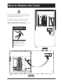
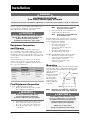
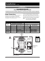
g
ZTX SERIES
40-400 Amps
GE Zenith Controls
62 R -20 0 0C
7/02
Operation and Maintenance Manual
Authorized Service
For GE parts and service, call: 773 299-6600
Table of Contents
Page
Introduction . . . . . . . . . . . . . . . . . . . . . . . . . . . . . .1ii
How to Remove the Cover . . . . . . . . . . . . . . . . . . .11
Installation . . . . . . . . . . . . . . . . . . . . . . . . . . . . . . .12
Equipment Inspection and Storage . . . . . . . .12
Final Equipment Inspection . . . . . . . . . . . . . .12
Mounting . . . . . . . . . . . . . . . . . . . . . . . . . . . .12
Power Connections . . . . . . . . . . . . . . . . . . . . .13
Engine Start Control Connections . . . . . . . . .14
RM4 Exerciser Option . . . . . . . . . . . . . . . . . .15
Functional Test . . . . . . . . . . . . . . . . . . . . . . . .16
RMF Control Interface . . . . . . . . . . . . . . . . . . . . . .17
Optional Indicator LED’s . . . . . . . . . . . . . . . .17
Optional Pushbuttons . . . . . . . . . . . . . . . . . . .17
Automatic Transfer Generator Testing . . . . . .18
Transfer Generator Testing . . . . . . . . . . . . . . .18
LED Diagnostic Flash Codes . . . . . . . . . . . . . .18
Automtic Generator Exerciser . . . . . . . . . . . .19
Selecting Exercisor without Transfer . . . . . . .19
Selecting Exercisor with Transfer . . . . . . . . . .19
Page
Engine Controller Accesoory Board . . . . . . . . . . .110
Example Systems . . . . . . . . . . . . . . . . . . . . . . . . . .11
Partial Coverage Systems . . . . . . . . . . . . . . . . .11
Total Coverage Systems . . . . . . . . . . . . . . . . . .11
Typical Diagrams . . . . . . . . . . . . . . . . . . . . . . . . . .12
Power Circuit Schematic . . . . . . . . . . . . . . . . .12
Power Panel Layout . . . . . . . . . . . . . . . . . . . . .12
Interconnect Plug . . . . . . . . . . . . . . . . . . . . . .12
Troubleshooting . . . . . . . . . . . . . . . . . . . . . . . . . . .13
General Troubleshooting . . . . . . . . . . . . .13, 14
Introduction
GE Zenith Transfer Switches are used to provide a continuous source of power for lighting and other critical loads by
automatically transferring from the normal source of power to an emergency source of power in the event that the normal source voltage falls below preset limits.
Voltage sensing and system control is performed via a state-of-the-art microcontroller located on the cabinet door. It is
designed to give highly accurate control of the transfer switch system.
All GE Zenith transfer switches are designed for use on emergency or standby systems, and are rated for total system or
motor loads. Transfer switches are UL Listed under Standard 1008 and CSA Certified under Standard C22.2 No. 178 and
IEC Listed under Standard 947.
NOTE:
A protective device such as a molded care circuit breaker or fused
disconnect switch MUST be installed on both sources of incoming
power for circuit potection and as a disconnection device.
How to Remove the Cover
Loosen but do not remove four cover screws. Lift cover
off the four screws and hang on two screws (2 bottom
or 2 right-hand). See Figure i and ii.
This will prevent damage to the cable. The cable may
also be disconnected at the controller or keypad.
NOTE:
Reattach cable before installing cover.
DANGER
HAZARDOUS VOLTAGE
Will shock, burn or cause death.
Do not remove cover until ALL
power is disconnected.
Re-installation of cover is required
after maintenance or service.
Figure i
Figure ii
■ GE Zenith Controls
ZTX Operation and Maintenance Manual (62R-2000)
1■
Installation
DANGER
HAZARDOUS VOLTAGE
(Can Cause Severe Injury or Death)
Turn OFF all power before installation, adjustment, or removal of transfer switch or any of its components.
The safe operation of your switch is GE Zenith’s focus.
The proper storage, installation, operation and maintenance will help increase the life of the switch.
NOTE:
5.
CAUTION
Make sure that all covers and barriers are
installed and properly fastened.
NOTE:
Due to hazardous voltage and current, GE Zenith recommends that a GE Zenith Certified technician or a
qualified electrician must perform the
installation and maintenance of the switch.
Equipment Inspection
and Storage
Once you have received the transfer switch, inspect
it for any damage. This includes damage to the enclosure, power panel, control panel and wiring harness. If
any damage is found or suspected, file a claim as soon as
possible with the carrier and notify the nearest GE Zenith
representative.
Before installation, it is necessary to store the transfer
switch in a clean dry place, protected from dirt and
water. Provide ample air circulation and heat, if necessary, to prevent condensation.
Storage
Temperature
-30°C to
+75°C
(-22°F to
+167°F)
Operating
Temperature
(Ambient):
-20°C to +65°C
(-4°F to +149°F)
Humidity
5% to 95%
(non-condensing)
Final Equipment Inspection
Prior to energizing the transfer switch:
1. Remove any debris incurred, with a vacuum,
due to shipment or installation.
WARNING
Do not use a blower since debris may
become lodged in the electrical and
mechanical components and cause damage.
2.
3.
4.
■2
Verify that all cabled connections are correct.
Check engine start connections and verify
the correct connection of all control wires.
Check the lug torque values of the power
connections.
Lug torque values are specified
in the power panel manual.
Power panels ship from GE Zenith
in the Normal Position.
Each GE Zenith transfer switch is factory wired and
tested. A complete information package is furnished
with each switch which includes:
a. Sequence of operation.
b. Description and operation of
all accessories supplied.
c. Power panel connection diagram
and schematic.
d. Description and identification of
all customer field connections.
Installation of GE Zenith transfer switches includes:
a. Mounting the transfer switch cabinet.
b. Connection of all Normal, Emergency,
and Load cables or bus bars.
c. Connection of external control
circuits as required.
Mounting
Adequate lifting means must be used to mount the transfer
switch into place. The recommended method for moving
the transfer switch using the lifting eyes, where supplied,
and a spreader bar is
illustrated here.
SPREADER BAR
45°
Enough room should H
be allowed to open
the cabinet doors
fully for inspection
LIFTING EYES
and servicing of the
switch per NEC and
local codes.
CABINET
NOTE:
D
When lifting the switch using a spreader bar,
height H must be equal to half of distance D.
CAUTION
Before drilling conduit entry holes or any
accessory mounting holes, cover and protect
the switch and control panel to prevent dirt
and metal fragments from entering the
mechanical and electrical components.
Failure to do so may result in
damage and malfunction of the switch.
ZTX Operation and Maintenance Manual (62R-2000)
GE Zenith Controls ■
Installation
(cont’d)
DANGER
HAZARDOUS VOLTAGE
(Can Cause Severe Injury or Death)
Turn OFF all power before installation, adjustment, or removal of transfer switch or any of its components.
Connect the Normal, Emergency, and Load conductors
to the clearly marked terminals on the transfer switch.
Remove surface oxides from cables by cleaning with a
wire brush. Verify that all connections are correct before
tightening the lugs. All cable lug connections must be
tightened to the proper torque values as shown in Table 2.
Power Connections
GE Zenith transfer switches are supplied with UL listed
solderless screw type terminals as standard for the
Normal, Emergency and Load power connections.
Table 1 lists the number and sizes of cable lugs supplied
as standard for each switch amp rating.
NOTE:
Do not run cables or wiring behind
front-connected transfer switches.
Screw Type Terminals for External Power Connections
Switch Size
(Amps)
Fully Rated Neutral Bar (When Required)
Utility, Generator and Load Terminals
Cable Per Pole
Range of Wire Sizes
No. of Cables
Range of Wire Sizes
40
1
#8 to 3/0 AWG
3
#8 to 1/0 AWG
80
1
#8 to 3/0 AWG
3
#8 to 1/0 AWG
100
1
#8 to 3/0 AWG
3
#8 to 1/0 AWG
150
1
#8 to 3/0 AWG
3
#8 AWG to 300 MCM
200, 225, 250*
1
#6 AWG to 250 MCM
3
#6 AWG to 300 MCM
300, 400
1
#4 AWG to 600 MCM
3
#4 AWG to 300 MCM
Table 1
LOAD
TERMINALS
* IEC Rating Only
UTILITY
TERMINALS
T1
T2
T3
Tip!
N3
Install
load
cables
first.
OPTIONAL A4 CONTACT
N1
BR
N2
OPERATES WHEN IN
UTILITY POSITION
JP
Exerciser
CONTROLLER
OPTIONAL ENGINE CONTROLS
OR AIR CONDITION DISCONNECT
OR 3 PHASE BOARD
SWITCH
POSITION
INDICATOR
ENGINE
START
N
E1
E2
3 AND 4 POLE ONLY
E3
OPTIONAL A3 CONTACT
GENERATOR
TERMINALS
T = Load
N = Utility
OPERATES WHEN IN
GENERATOR POSITION
E = Generator
Figure 2 - Power Panel
■ GE Zenith Controls
ZTX Operation and Maintenance Manual (62R-2000)
3■
Installation
(cont’d)
DANGER
HAZARDOUS VOLTAGE
(Can Cause Severe Injury or Death)
Turn OFF all power before installation, adjustment, or removal of transfer switch or any of its components.
Control Connections
Note:
N = Utility Position
E = Generator Position
Connecting Engine Start may cause Generator to
start. Before connecting, turn Generator OFF.
Figure 4
1
2
3
JP
A B
With the Generator breaker open and the Generator
control switch off, install the Generator start connections.
6
5
4
B A
Manual operation is possible for maintenance purposes only.
Manual operation of the switch can be checked before it
is operated electrically.
Exerciser
CONTROLLER
Close to Start
Opens to Stop
Contact Rating
28Vdc @ 5 amps
Figure 3
Engine Start
Contact Output
The engine-start terminals are clearly identified by a
label on the microcontroller backplate. In the case of
manual transfer switches, or in other applications not
requiring the microprocessor, clearly marked terminal
blocks are provided in the upper left corner of the control
panel for the engine start control wires.
Terminals for field connections to the A3 Emergency
auxiliary contacts and the A4 Normal auxiliary contacts
are also provided. These terminals are clearly marked
and appear on the side of the power panel. On 400 amp
metal frame units these terminals appear on the bracket
above the operator handle.
g
GE Zenith Controls
VOLTS AMPS -
SYSTEM VOLTS:
Tightening Torque for Lugs
Torque
Socket Size
Across Flats
Lb. - In.
Lb. - Ft.
1/8
45
4
5/32
100
8
3/16
120
10
7/32
150
12
1/4
200
17
5/16
275
23
3/8
375
31
1/2
500
42
9/16
600
50
Table 2
SERIAL NUMBER:
RATING:
With all power off, insert a Phillips screwdriver or equivalent
size tool into the manual operator socket and operate
the transfer switch between the Utility and Generator
positions. The transfer switch should operate smoothly
without binding. Return the switch to the Utility position,
remove the screwdriver.
HZ PHASE -
MODEL NUMBER:
Figure 3
■4
ZTX Operation and Maintenance Manual (62R-2000)
GE Zenith Controls ■
Installation
(cont’d)
DANGER
HAZARDOUS VOLTAGE
(Can Cause Severe Injury or Death)
Turn OFF all power before installation, adjustment, or removal of transfer switch or any of its components.
ATTENTION!
This applies only to the switches with the RM4-CAT
exerciser option:
Upon installation, connect the MX50/90 controller to a
9V battery (not supplied) via the harness that is connected to the controller. The battery should be placed
in the holder installed just above the controller. This is
to ensure that the setting in the exercisor clock are
retained in the event of power outage. The battery
should be replaced once a year. If the battery is not
installed and/or replaced as recommended, the
exerciser clock will lose its settings and the exerciser
will not work.
Should the harness become disconnected in shipping,
take the controller cover off and plug the harness in the
receptacle in the top right corner of the MX controller.
Reinstall the cover and connect the battery.
Battery and Holder
Battery Harness
MX50/90 Controller
■ GE Zenith Controls
ZTX Operation and Maintenance Manual (62R-2000)
5■
Installation
(cont’d)
DANGER
HAZARDOUS VOLTAGE
(Can Cause Severe Injury or Death)
Turn OFF all power before installation, adjustment, or removal of transfer switch or any of its components.
Functional Test
Functional Test
The functional testing of the transfer switch consists of
electrical tests described in this section. Before proceeding, read and understand all instructions and review the
operation of all accessories provided.
Initiate the electrical transfer test by opening the Utility
side breaker. The delay to engine start timer (P) begins
its timing cycle. After the P timer has completed its timing
cycle, the engine start contacts close to start the generator.
To begin the test, close the Utility source circuit breaker.
The controller will illuminate the optional Utility Available
LED when proper voltage is sensed. Verify the phase to
phase voltages at the Utility line terminals.
When Generator voltage and frequency reach preset pickup
points the optional Generator Available LED illuminates.
Simultaneously, the delay to Generator timer (W) begins
its timing cycle. When the W time delay is completed the
switch will transfer to Generator. The optional Utility
Position LED goes off, and the optional Generator
Position LED illuminates.
Next, close the Generator source breaker and start the
engine generator. The optional Generator Available
LED will illuminate when proper voltage and frequency
levels is sensed. If Generator LED is flashing, use the Reset
button to clear. Check the phase to phase voltages at the
Generator line terminals. On three phase units, verify
that the phase rotation of the Generator source is same
as Utility source.
After the sources have been verified, shut down the engine
generator, and put the starting control in the automatic position. Complete the visual inspection of the transfer switch,
and replace the cabinet cover (or close the cabinet door).
Reclose the Utility breaker to retransfer to Utility. The
delay to Utility timer (T) begins its timing cycle. When
the T timer has completed its timing cycle, the switch will
transfer into Utility. The optional Generator Position
LEDs go off, and the Utility Position LED illuminates.
The delay engine stop timer (U) begins its timing cycle.
The generator runs unloaded for the duration of the U
timing cycle. When the timer completes its timing cycle,
the generator will stop. The optional Generator Available
LED goes off.
Factory Settings
Factory Settings
Utility Pickup Voltage
90% Nominal
Line Voltage
Generator Pickup Voltage
90% Nominal
Line Voltage
Utility Dropout Voltage
80% Nominal
Line Voltage
Generator Dropout Voltage
80% Nominal
Line Voltage
Utility Pickup Frequency
90% Nominal
Line Frequency
Generator Pickup Frequency
95% Nominal
Line Frequency
(T) Timer/Delay to Utility
5 minutes*
(P) Timer/Engine Start
5 seconds*
(U) Timer/Engine
Cool Down
5 minutes*
(W) Timer/Delay to Generator
20 seconds*
Table 3
* Factory default settings — customer time settings may vary due to specifications from the generator supplier.
■6
ZTX Operation and Maintenance Manual (62R-2000)
GE Zenith Controls ■
RM4 Control Interface (Optional )
DANGER
HAZARDOUS VOLTAGE
(Can Cause Severe Injury or Death)
Turn OFF all power before installation, adjustment, or removal of transfer switch or any of its components.
Optional Indicator LEDs
A Utility available Green LED. When on, indicates the
utility source is acceptable.
B Utility position Green LED. When on, indicates that
the transfer switch is connected to the utility.
C Generator available Red LED. When on, indicates
the generator source is acceptable.
D Generator position Red LED. When on, indicates that
the transfer switch is connected to the generator.
E Load Amber LED. When on, indicates that the load
is connected to an acceptable source.
C
D
F
A
H
B
I
Figure 5
E
G
Optional Pushbuttons
F.F Generator Start/Stop push button. Pressing and
holding this button for approximately 5 seconds
will cause the generator to start. Pressing this button
a second time will stop the generator.
G Exerciser Start/Stop push button. When this button
G.
is depressed it will enable the automatic exerciser
mode. Pressing this button a second time will cancel
the automatic exerciser mode.
H Reset push button. Pressing this button will clear the
H.
fault indications.
I. I Transfer push button. Pressing this button will force
the unit to transfer from one position to another when
both sources are available.
■ GE Zenith Controls
ZTX Operation and Maintenance Manual (62R-2000)
7■
RM4 Control Interface (Optional )
(cont’d)
DANGER
HAZARDOUS VOLTAGE
(Can Cause Severe Injury or Death)
Turn OFF all power before installation, adjustment, or removal of transfer switch or any of its components.
Automatic Transfer Generator
Testing (One Time Test)
Transfer Generator Testing
(Forcing Operation with Keypad)
Verify that the transfer switch UTILITY available and
position LEDs are illuminated. A
B
Verify that the transfer switch UTILITY available and position LEDs are illuminated. A
B
+
Press and hold the GENERATOR START/STOP button
and the TRANSFER button I for 5 seconds. This will
cause the generator to start. Once the generator
C has
started, the Generator LED will illuminate.
+
F
Once the GENERATOR power LED C has come on, the
transfer switch will now switch the load to the Generator.
The GENERATOR position LED will illuminate. D
The transfer switch will be connected to the generator
for 5 minutes.* Then the switch will automatically return to
the utility and the UTILITY Position LED will illuminate. B
The generator will cool down for 5 minutes (U Timer)
and then shut down. The GENERATOR LED will go off.
Verify that the GENERATOR available LED
has illuminated. C
Press the TRANSFER button. I The switch will transfer
to the Generator source position. The GENERATOR
position LED will now be illuminated. D
Pressing the TRANSFER button I again will cause the
unit to transfer to the utility power source. The UTILITY
position LED will illuminate. B
C
This completes the automatic test.
* Pressing and releasing the generator Start/Stop button
will cancel current test.
Press and hold the GENERATOR START/STOP button for 5
seconds. This will start the generator. F
Pressing the GENERATOR START/STOP button will stop
the generator. F
NOTE:
Transfer will cause short interruption of power.
LED Diagnostic Flash Codes
Rapidly Flashing Generator
Availability LED C
Generator failed to start.
Rapidly Flashing Generator
Position LED
D
Switch did not transfer to Generator position.
Generator starts but failed to reach proper
operating parameters.
Generator became over loaded for an extended
period of time.
Optional generator crank board (see generator
fault flash table on page 14)
■8
Rapidly Flashing Utility
Position LED
B
Switch did not transfer to Utility position.
NOTE:
All fault alarms can be cleared by
depressing the reset button.
ZTX Operation and Maintenance Manual (62R-2000)
GE Zenith Controls ■
RM4 Control Interface (Optional )
(cont’d)
DANGER
HAZARDOUS VOLTAGE
(Can Cause Severe Injury or Death)
Turn OFF all power before installation, adjustment, or removal of transfer switch or any of its components.
Automatic Generator Exerciser
DANGER
The automatic generator exerciser comes preset with
a 28-day exerciser schedule (the customer unit’s preset day
cycle may vary due to specifications from the generator supplier).
The exerciser, when enabled, will automatically start the
generator every twenty-eighth day and run the unit loaded
or unloaded for 10 minutes. The exerciser interval is
selectable through (JP) jumper selection on the controller board. The selections are 7, 14, 21 or 28 day.
Turn OFF all power before selecting.
JP (CDT SELECT)
See Figure 3, Page 4
21 Day
4
4
5
To start the automatic exerciser without transfer, depress
the Exerciser Start/Stop button. The generator will start
and run for 10 minutes.* Once this first exercise is complete, the generator LED will flash at a 1-second interval
indicating the exerciser is enabled. Once the exerciser
times out (7, 14, 21 or 28 day interval), the generator
will start and run again for 10 minutes. This will repeat
until the exerciser is disabled. To stop the exerciser mode,
depress the exerciser Start/Stop again and the generator
light will stop flashing, indicating the exerciser mode
has been canceled.
5
6
Selecting Exerciser Without Transfer
6
7 Day
B
B
A
A
28 Day
4
4
5
5
6
6
14 Day
B
A
B
A
JP (VOLTAGE/FREQUENCY SELECT)
Selecting Exerciser With Transfer
Transfer will cause short interruption of power.
■ GE Zenith Controls
B
A
B
60 Hz
B
50 Hz
2
2
1
A
B
240 V
A
2
1
A
B
220 V
Figure 6
ZTX Operation and Maintenance Manual (62R-2000)
3
NOTE:
208 V
3
Pressing and releasing the generator Start/Stop button will cancel
the current test. The exerciser will go off at approximately the same
time it was started (7, 14, 21 or 28 days) later.
Do not adjust the jumper positions.
This service to be performed by qualified personnel only.
A
*
See Figure 3, Page 4
1
To enable the automatic exerciser with transfer, depress
the Exerciser Start/Stop button and the transfer button.
The generator will start and the load will be transferred to
, the load will be transferred
the generator. After 10 minutes*
back to the utility. Once this first exercise is complete, the
generator LED and the Generator position LED will flash
at a 1-second interval indicating the exerciser is enabled.
Once the exerciser has timed out (7, 14, 21 or 28 day
interval), the generator will start and transfer the load
to Generator power for 10 minutes. At the end of this
10-minute period, the unit will transfer the load back to
the utility and the generator will shut off. This will repeat
until the exerciser is disabled. To stop the exerciser
mode, depress the exerciser Start/Stop again and the
generator light will stop flashing, indicating the exerciser
mode has been canceled.
9■
Engine Controller Accessory Board (Optional)
Oil Pressure Sensor Input
Fuel/Run Contact Output
(Oil pressure contact to be normally open, held closed
by adequate oil pressure)
Approximately five seconds after emngine starter signal
is sent, if terminal X3 is open to ground or returns to
open state thereafter the generator Starter and Fuel/Run
outputs are opened and locked out. After cause is determined and corrective action is taken and verified by qualified technician, controller can be reset via reset button.
This output is activated closed whenever the engine is
running. This will keep the fuel valve open as needed,
and will cut fuel supply during the above mentioned
lockouts or when the engine is no longer called to run.
Start Contact Output
This output is activated closed during cranking of the
engine. Output will deactivate once the controller senses
that the generator output has reached 33% of frequency
indicating engine has reached running RPM.
Temperature Sensor Input
(Temperature sensor contact to be normally open,
closed by over-temperature condition)
Approximately five seconds after the engine starter signal
is sent, if terminal X1 is connected to ground Starter and
Fuel/Run outputs are opened and locked out. After
cause is determined and corrective action is taken and
verified by a qualified technician, the controller can be
reset via the reset button.
Generator Battery Input
This input is required to support the controller’s operation.
Controller
Generator Battery Input
(12 Vdc)
Engine
Controller
X9
X10
X5
X6
+
+
–
+
–
X1
X2
X3
X4
–
Start Contact Output
(28 Vdc @ 5 amps)
Input
Temperature
Sensor
(12 Vdc)
■ 10
Input
Oil Pressure
Sensor
Fuel/Run Contact Output
(28 Vdc @ 5 amps)
(12 Vdc)
ZTX Operation and Maintenance Manual (62R-2000)
GE Zenith Controls ■
Example Systems
Partial Coverage System
Loads
Transfer Switch
Utility
Source
Circuit
Breaker
Generator
Source
Utility Panel
Loads
Distribution Panel
Total Coverage System
Transfer Switch
Utility
Source
Circuit
Breaker
Circuit
Breaker
Generator
Source
Main
Breaker
Panel
All Loads
■ GE Zenith Controls
ZTX Operation and Maintenance Manual (62R-2000)
11 ■
Typical Diagrams
Power Circuit Schematic
Power Panel Layout
Interconnect Plug
5
1
CCN
SN
SCOM
SE
E2
N1
N2
CCE
E1
10
6
OPTIONAL 3
4
2
■ 12
ZTX Operation and Maintenance Manual (62R-2000)
N2 E3
N3 E2
3
1
GE Zenith Controls ■
Troubleshooting
DANGER
HAZARDOUS VOLTAGE
(Can Cause Severe Injury or Death)
Turn OFF all power before installation, adjustment, or removal of transfer switch or any of its components.
Service must be performed by qualified personnel.
Symptom
Generator will not start
Transfer switch does not
transfer to Utility
Transfer switch does not
transfer to Generator
Generator will not stop
Possible Cause
Corrective Action
P timer has not lapsed
See factory settings on Page 6
Generator control switch not in Auto
Refer to generator instruction manual
Engine Start contact not wired
to generator
See Figure 3, Page 4
Starter battery is dead
Refer to generator instruction manual
No fuel
Refer to generator instruction manual
T timer has not lapsed
See factory settings on Page 6
Exercise in progress
See Page 9
Utility breaker open or tripped
Clear fault and reset
Utility voltage out of range
Wait for utility to return to acceptable
level. See factory settings on Page 6.
Control harness unplugged
With all power disconnected,
reconnect harness
W timer has not lapsed
See factory settings on Page 6
Generator breaker open or tripped
Refer to generator instruction manual
Generator voltage out of range
Refer to generator instruction manual
Control harness unplugged
With all power disconnected,
reconnect harness
U timer has not lapsed
See factory settings on Page 6
Exercise in progress
See page 9
Engine control switch in run position
Refer to generator instruction manual
Keypad cable unplugged
With all power disconnected,
reconnect harness
Sources unavailable and/or source
breakers tripped or open
Clear fault and reset breakers and/or
check source availability
All LEDs off
■ GE Zenith Controls
ZTX Operation and Maintenance Manual (62R-2000)
13 ■
Troubleshooting
(cont’d)
DANGER
HAZARDOUS VOLTAGE
(Can Cause Severe Injury or Death)
Turn OFF all power before installation, adjustment, or removal of transfer switch or any of its components.
Service must be performed by qualified personnel.
Generator Fault Flash Table
Generator Failed to Start (GFS Timeout)
2 Flashes + 2 Missing
Generator Under-Speed Fault
3 Flashes + 2 Missing
Generator Over-Speed Fault
4 Flashes + 2 Missing
Generator Over-Temperature Fault
5 Flashes + 2 Missing
Generator Low-Oil-Pressure Fault
6 Flashes + 2 Missing
NOTE:
■ 14
Faults that trigger the “original” SAG timer (emergency source not available for longer than the GS timer interval)
will continue to be indicated on the “Emergency Source” LED at the original continuous 5 Hz rate.
ZTX Operation and Maintenance Manual (62R-2000)
GE Zenith Controls ■
■ GE Zenith Controls
ZTX Operation and Maintenance Manual (62R-2000)
15 ■
g
GE Zenith Controls
GE Industrial Systems –
Power Equipment Business
830 W. 40 th Street, Chicago, IL 60609 USA
773 299-6600, Fax: 630 850-6899
www.zenithcontrols.com