1
Î
GE Fanuc Automation
Programmable Control Products
TCP/IP Ethernet Communications
for the Series 90 -30 PLC
t
User’s Manual
GFK-1084B
August, 1997
GFL–002
Warnings, Cautions, and Notes
as Used in this Publication
Warning
Warning notices are used in this publication to emphasize that
hazardous voltages, currents, temperatures, or other conditions that
could cause personal injury exist in this equipment or may be
associated with its use.
In situations where inattention could cause either personal injury or
damage to equipment, a Warning notice is used.
Caution
Caution notices are used where equipment might be damaged if care is
not taken.
Note
Notes merely call attention to information that is especially significant to
understanding and operating the equipment.
This document is based on information available at the time of its publication. While
efforts have been made to be accurate, the information contained herein does not
purport to cover all details or variations in hardware or software, nor to provide for
every possible contingency in connection with installation, operation, or maintenance.
Features may be described herein which are not present in all hardware and software
systems. GE Fanuc Automation assumes no obligation of notice to holders of this
document with respect to changes subsequently made.
GE Fanuc Automation makes no representation or warranty, expressed, implied, or
statutory with respect to, and assumes no responsibility for the accuracy, completeness,
sufficiency, or usefulness of the information contained herein. No warranties of
merchantability or fitness for purpose shall apply.
The following are trademarks of GE Fanuc Automation North America, Inc.
Alarm Master
CIMPLICITY
CIMPLICITY Control
CIMPLICITY PowerTRAC
CIMPLICITY 90-ADS
CIMSTAR
Field Control
GEnet
Genius
Genius PowerTRAC
Helpmate
Logicmaster
Modelmaster
PowerMotion
ProLoop
PROMACRO
Series Five
Series 90
Copyright 1995-1997 GE Fanuc Automation North America, Inc.
All Rights Reserved
Series One
Series Six
Series Three
VuMaster
Workmaster
Preface
Content of This Manual
Chapter 1.
Introduction: Discusses the TCP/IP Ethernet Interface, its communications
capabilities, and generally how to get your system running. Also included
is a quick guide to the manual.
Chapter 2.
Installing the TCP/IP Ethernet Interface: Describes the basic features of
the TCP/IP Ethernet Interface, the installation and power-up of the Interface, and a procedure for the initial checkout of the Interface on your Ethernet cable.
Chapter 3.
Programming Communications Requests: Describes the ladder programming necessary for communications between PLCs.
Chapter 4.
Troubleshooting: Describes troubleshooting and problem isolation for the
Ethernet Interface.
Appendix A.
Glossary of Terms
Appendix B.
Communications Port Characteristics
Appendix C.
Advanced Information About IP and MAC Addresses
Appendix D.
Sample Ladder Program
Appendix E.
PC Software loader
Related Publications
GFK-1186
TCP/IP Ethernet Communications for the Series 90 PLC Station Manager Manual
GFK-0356
Series 90 -30 Programmable Controller Installation Manual
GFK-0466
Logicmaster 90
t
GFK-0467
t Series 90t-30/20/Micro Programming Software User’s Manual
Using CIMPLICITYR Control
Series 90t-30/20/Micro Programming Software Reference Manual
GFK-0870
Host Communications Toolkit for C/C++ Applications User’s Manual
GFK-1063
Host Communications Toolkit for Visual Basic Applications User’s Manual
GFK-1026
Host Communications Drivers for Microsoft Windows User’s Manual
GFK-1295
We Welcome Your Comments and Suggestions
At GE Fanuc Automation, we strive to produce quality technical documentation. After
you have used this manual, please take a few moments to complete and return the
Reader ’s Comment Card located on the next page.
GFK-1084B
iii
""!
")-+ ")-+ '-+(.-#(' 1
*' 5*'3/'5 /5'3(#%' ;
08 50 #,' 5*' :45'. !03, ;
6+%, 6+&' 50 5*' #/6#- ;
',-%%#'! -" -"+'- '-+ 1
5*'3/'5 /5'3(#%' #3&8#3' 7'37+'8 ;
0#3& /&+%#5034 ;
'45#35 6550/ ;
'3+#- 0354 ;
3#/4%'+7'3 035 ;
'(#6-5 5#5+0/ &&3'44 #$'- ;
'3+#- 6.$'3 #$'- ;
+(.+ ',-%%#'! -" -"+'- '-+ #' -" 26+1.'/5 '26+3'& 50 '3(03. 5*' /45#--#5+0/ 30%'&63'4 ;
5*'3/'5 /5'3(#%' /45#--#5+0/ ;
+(.+ (' #!.+#'! -" -"+'- '-+ /#-"
(!#&,-+ 1 (' #!.+-#(' ( -/+ 1
+(.+ (' #!.+#'! -" -"+'- '-+ .,#'!
('-+(% 1
+(.+ +# 0#'! +()+ (/+1) ( -" -"+'- '-+ 1
08'3+/);61 5*' 5*'3/'5 /5'3(#%' ;
30$-'.4 63+/) 08'3;61 ;
+(.+ #'!#'! -"+'- '-+ , (' -" -/(+$
1
+/)+/) 5*' /5'3(#%' (30. #
")-+ " *045 03 # 6//+/) 0(58#3'
;
+(!+&&#'! (&&.'#-#(', *.,-, 1
-#(' " (&&.'#-#(', *.,- 1
536%563' 0( 5*' 0..6/+%#5+0/4 '26'45 %
1
;
6/%5+0/ -0%, ;
0..#/& -0%, ;
*#//'- 0..#/&4 ;
5#564 #5# ;
*' 0)+% 30)3#. 0/530--+/) 9'%65+0/ 0( 5*' 6/%5+0/ -0%, ;
1'3#5+0/ 0( 5*' 0..6/+%#5+0/4 '26'45 ;
" " #"! ! ! # % ##!" $
""!
*!&% +%*!&% #&" % &$$% #&"
.
+( 70&6,10 .1&- ;
+( 1//$0' .1&- ;
*!&% %%# &$$%) 56$%.,5+,0* $ +$00(. ;
%146,0* $0' (;6$5-,0* $ +$00(. ;
(64,(8,0* (6$,.(' 6$675 10 6+( +$00(. ;
2(&,):,0* $ (6914- ''4(55 ;
56$%.,5+ ($' +$00(. ;
56$%.,5+ "4,6( +$00(. ;
(0' 0)14/$6,10 (2146 ;
%146 +$00(. ;
(64,(8( (6$,.(' +$00(. 6$675 ;
*!&% **+) * ''%!, %
.
:2(5 1) 6$675 $6$ ;
(5&4,26,10 1) 6+( 6$675 $6$ ;
76276 1) 6+( 70&6,10 .1&- ;
76276 1) 6+( 70&6,10 .1&- ;
6$675 ,65 ;
1//70,&$6,105 6$675 "14'5 ;
,014 4414 1'(5 ;
*!&% &%*(&##!% &$$+%!*!&%) !% * ( (&($ '*( .
.
55(06,$. .(/(065 1) 6+( $''(4 41*4$/ ;
417%.(5+116,0* #174 $''(4 41*4$/ ;
10,614,0* 6+( 1//70,&$6,105 +$00(. ;
(37(0&,0* 1//70,&$6,105 (37(565 ;
$6$ 4$05)(45 9,6+ 0( (2(6,6,10 ;
(&+#) &&*!% .
,$*0156,& 11.5 8$,.$%.( )14 417%.(5+116,0* ;
"+$6 61 '1 ,) :17 $0016 1.8( 6+( 41%.(/ ;
$7.6 $%.( ;
#&))(- .
1//10.: !5(' &410:/5 $0' %%4(8,$6,105 ;
.155$4: 1) (4/5 ;
" " #"! ! ! # % ##!" $
""!
$ $ ! %
--%)( (#!+ )+- 2
--%)( (#!+ )+- !--%(#, 2
--%)( (#!+ )+- %().-, 2
--%)( (#!+ )+- &! 2
)"-0+! ) !+ )+- !+%& )+- 2
)"-0+! ) !+ )+- %().-, 2
+- .'!+, ")+ (. &!, ( )(/!+-!+, 2
)"-0+! ) !+ )+- &! 2
$! )+- ")+ -$! -$!+(!- (-!+"! 2
-$!+(!- )+- %().-, 2
+(,!%/!+ )("%#.+-%)(, 2
%,*&1 !+'%(& !--%(#, 2
" ! %
+!,,!, 2
-!01, 2
.(!-, 2
+!,,!, 2
$ %
$ # %
$ ! %
'! ,,%#('!(- 2
'! !,)&.-%)( 2
)& &! '! !,)&.-%)( 2
'! !,)&.-%)( 2
'! !,)&.-%)( 2
'! ,#! 2
%
" " #"! ! ! # % ##!" $
Contents
Figure 1-1. Ethernet Communications System . . . . . . . . . . . . . . . . . . . . . . . . . . . . . . . . . . . . . . . . . . . . . .
1-1
Figure 1-2. The Main Tasks for Installing the Ethernet Interface . . . . . . . . . . . . . . . . . . . . . . . . . . . . . . .
1-4
Figure 2-1. Ethernet Interface . . . . . . . . . . . . . . . . . . . . . . . . . . . . . . . . . . . . . . . . . . . . . . . . . . . . . . . . . . . .
2-2
Figure 2-2. States of the Ethernet Interface . . . . . . . . . . . . . . . . . . . . . . . . . . . . . . . . . . . . . . . . . . . . . . . . .
2-18
Figure 3-1. Elements of the Communications Request . . . . . . . . . . . . . . . . . . . . . . . . . . . . . . . . . . . . . . .
3-2
Figure 3-2. Operation of the Communications Request for an Establish Read ChannelCommand . .
3-5
Figure 3-3. Format of the COMMREQ Status Word (CRS Word) . . . . . . . . . . . . . . . . . . . . . . . . . . . . . .
3-36
Figure 3-4. Format of the Detailed Channel Status Words (DCS Words) . . . . . . . . . . . . . . . . . . . . . . . .
3-36
Figure B-1. Serial Cable (IC693CBL316A) to Connect the Personal Computer to the
Station Manager Port . . . . . . . . . . . . . . . . . . . . . . . . . . . . . . . . . . . . . . . . . . . . . . . . . . . . . . . . .
B-3
Figure B-2. Software Loader Cable Assembly (IC690ACC901) . . . . . . . . . . . . . . . . . . . . . . . . . . . . . . . . .
B-5
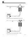
Figure B-3. 10Base2 Transceiver Configuration with Detachable Transceiver Cable (Available as
GE Fanuc Part Number IC649AEA101 . . . . . . . . . . . . . . . . . . . . . . . . . . . . . . . . . . . . . . . . . . .
B-7
Figure B-4. 10Base2 Transceiver Configuration with Built-in Transceiver Cable . . . . . . . . . . . . . . . . . .
B-8
Figure B-5. 10Base2 Transceiver Configuration using BNC “T” Connector . . . . . . . . . . . . . . . . . . . . . .
B-8
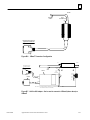
Figure B-6. 10BaseT Transceiver Configuration . . . . . . . . . . . . . . . . . . . . . . . . . . . . . . . . . . . . . . . . . . . . .
B-9
Figure B-7. AAUI to AUI Adapter. Can be used to connect to 10Base5 (shown above) or 10BaseF . .
B-9
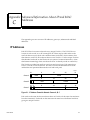
Figure C-1. IP Address Format for Network Classes A, B, C . . . . . . . . . . . . . . . . . . . . . . . . . . . . . . . . . . .
C-1
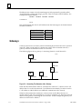
Figure C-2. Connecting Two Networks with a Gateway . . . . . . . . . . . . . . . . . . . . . . . . . . . . . . . . . . . . .
C-2
Figure C-3. Network Configuration Using a Subnet Mask . . . . . . . . . . . . . . . . . . . . . . . . . . . . . . . . . . . .
C-3
Figure E-1. Software Loader Cable Assembly (IC690ACC901) . . . . . . . . . . . . . . . . . . . . . . . . . . . . . . . . .
E-1
GFK-1084B
TCP/IP Ethernet Communications User’s Manual - August 1997
viii
Contents
Table 2-1. Problems During Power-Up . . . . . . . . . . . . . . . . . . . . . . . . . . . . . . . . . . . . . . . . . . . . . . . . . . . . .
2-19
Table 3-1. Time Unit Values for Read/Write Repetition Period . . . . . . . . . . . . . . . . . . . . . . . . . . . . . . . . .
3-12
Table 3-2. Series 90 PLC Memory Types . . . . . . . . . . . . . . . . . . . . . . . . . . . . . . . . . . . . . . . . . . . . . . . . . . .
3-13
Table 3-3. Status Bits (LIS Bits and Channel Status Bits) . . . . . . . . . . . . . . . . . . . . . . . . . . . . . . . . . . . . . .
3-34
Table 3-4. Major Error Codes . . . . . . . . . . . . . . . . . . . . . . . . . . . . . . . . . . . . . . . . . . . . . . . . . . . . . . . . . . . . .
3-37
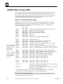
Table 3-5. Minor Error Codes for Major Error Codes 05H (at Remote Server PLC) and
85H (at Client PLC) . . . . . . . . . . . . . . . . . . . . . . . . . . . . . . . . . . . . . . . . . . . . . . . . . . . . . . . . . . .
3-38
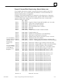
Table 3-5. Minor Error Codes for Major Error Codes 5H and 85H (Continued) . . . . . . . . . . . . . . . . . .
3-39
Table 3-6. Minor Error Codes for Major Error Code 11H (at Remote Server PLC) . . . . . . . . . . . . . . . .
3-39
Table 3-7. Minor Error Codes for Major Error Code 90H (at Client PLC) . . . . . . . . . . . . . . . . . . . . . . . .
3-40
Table 4-1. PLC Fault Table Descriptions . . . . . . . . . . . . . . . . . . . . . . . . . . . . . . . . . . . . . . . . . . . . . . . . . . . .
4-3
Table 4-1. PLC Fault Table Descriptions (Continued) . . . . . . . . . . . . . . . . . . . . . . . . . . . . . . . . . . . . . . . . .
4-4
Table B-1. Station Manager Port Pinouts . . . . . . . . . . . . . . . . . . . . . . . . . . . . . . . . . . . . . . . . . . . . . . . . . . .
B-2
Table B-2. Serial Cable (IC693CBL316A) Connector Pinouts . . . . . . . . . . . . . . . . . . . . . . . . . . . . . . . . . .
B-3
Table B-3. Software Loader Port Pinout . . . . . . . . . . . . . . . . . . . . . . . . . . . . . . . . . . . . . . . . . . . . . . . . . . . .
B-4
Table B-4. Cables for Connecting the Software Loader Port to the RS-232 Port on Your PC . . . . . . . .
B-5
Table B-5. Pinouts of the AAUI Port . . . . . . . . . . . . . . . . . . . . . . . . . . . . . . . . . . . . . . . . . . . . . . . . . . . . . . .
B-6
GFK-1084B
TCP/IP Ethernet Communications User’s Manual - August 1997
ix
section level 1
figure bi level 1
table_big level 1
figure_ap level 1
table_ap level 1
Chapter Introduction
1
This manual describes the Ethernet Interface (IC693CMM321) for the Series 90-30 PLC.
This chapter provides an overview of the Ethernet Interface and covers the following
topics.
H
H
H
The Ethernet Interface,
How to Make the System Work,
Quick Guide to the Manual.
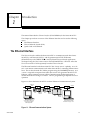
The Ethernet Interface
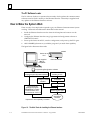
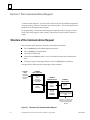
The Ethernet Interface enables the Series 90-30 PLC to communicate with other Series
90-30 PLCs, with Series 90-70 PLCs, with Logicmaster 90-30 TCP/IP Ethernet
(IC641SWP313), with CIMPLICITYR Control (IC641CTL9xx) and with applications
developed using the Host Communications Toolkit (IC641SWP05x). GE Fanuc offers the
Host Communications Toolkit separately from the Ethernet Interface.
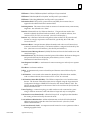
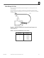
The Ethernet Interface for the Series 90-30 PLC has “client/server” capability. As a “client” it can initiate communications with other Series 90 PLCs containing Ethernet Interfaces. This is done from the PLC ladder program using the COMMREQ function. As a
“server” it responds to requests from other devices such as Logicmaster 90-30 TCP/IP
Ethernet, a Host computer running a Host Communications Toolkit application, or
another Series 90 PLC acting as a “client”. No PLC programming is required for server
operation.
Figure 1-1 shows the Series 90-30 PLC in a basic Ethernet Communications System.
Transceiver
Ethernet
Cable
Transceiver
Transceiver
Transceiver
Network
Connection
a45694
Transceiver
Network
Connection
Series 90–30
Series 90–30
Ethernet
Ethernet
PLC
PLC
Interface
Interface
Series 90–70
Ethernet
PLC
Interface
Host Computer or
Control Device Running a
Host Communications
Toolkit Application
R
CIMPLICITY Control or
Logicmaster 90 TCP/IP
Ethernet running on a PC
Figure 1-1. Ethernet Communications System
GFK-1084B
1-1
1
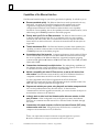
Capabilities of the Ethernet Interface
The Ethernet Interface brings to your PLC a great deal of capability. It will allow you to:
H Become operational quickly.
The Ethernet Interface is made operational with very
little effort. You need only install the Interface in the baseplate and, use the
Logicmaster configuration package or CIMPLICITY Control to store basic
configuration information to the module to make the basic server capability
functional. Client capability, that is, the capability to initiate communications, can be
added using the COMMREQ function in the ladder program.
H Directly attach your PLC to an Ethernet network.
The Ethernet Interface allows you
to directly attach the Series 90-30 PLC to an Ethernet LAN via a user-supplied
transceiver and AAUI cable, and to communicate with host computers and other
Series 90 PLCs on the local network. All Series 90-30 models and all rack styles are
supported.
H Transfer data between PLCs.
The Ethernet Interface provides client capability, the
capability to initiate communications to other Series 90 Ethernet Interfaces, using
COMMREQ functions in the ladder program.
H Access data using a Host computer.
Computer applications which use the GE Fanuc
Host Communications Toolkit can access data within the Series 90-30 PLC through
the server capability of the Ethernet Interface. Supported computer operating
systems include Windowsr, Windows NTr, HP-UX 9000, DEC VAX/VMSt, and DEC
Alpha AXP/VMSt.
H Communicate simultaneously to multiple devices.
The multiplexing capabilities of
the Ethernet Interface, along with Ethernet network’s high capacity, allow the PLC
to communicate with several other devices at the same time.
H Maintain compatibility with other GE Fanuc devices, as well as with devices from
other vendors. The GE Fanuc Series 90-30 PLC with TCP/IP Ethernet Interface is
compatible with the Series 90-70 PLC with TCP/IP Ethernet Interface.
It is also compatible with GE Fanuc Logicmaster 90-30 TCP/IP Ethernet,
CIMPLICITY Control and GE Fanuc HCT Ethernet products available on DEC, HP,
IBM, and other computer platforms runningTCP/IP.
H Diagnose and maintain your system, using diagnostic and station management tools.
You can find problems before they become serious. In the event that
communications software upgrades are needed, you can use a built-in serial port to
download the software to the Interface.
H Indirectly attach to other Local Area Networks and/or wide area networks via third
party IP routers. When configured to use an IP gateway (router), the Ethernet
Interface can communicate with remote PLCs and other nodes reachable through
the router.
H Communicate with remote computers via Serial Line Internet Protocol (SLIP) using
modems and/or serial lines. Using third party SLIP software, a remote host
computer can be attanched to a TCP/IP network.
tDEC, VAX, Alpha AXP, and VMS are trademarks of Digital Equipment Corporation.
rWindows and Windows NT are registered trademarks of Microsoft Corporation.
1-2
TCP/IP Ethernet Communications User’s Manual – August 1997
GFK-1084B
1
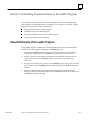
Attachment of the Ethernet Interface to the LAN
The AAUI port provides the electrical and mechanical interface to the user-provided
Ethernet transceiver cable, which connects the AAUI port to an external user-provided
transceiver. (The transceiver cable may be separate or built-in to the transceiver.) The
external transceiver is directly connected to the Ethernet cable.
Various Ethernet baseband media (10Base...) can be interconnected by appropriate repeaters. Capabilities and limitations are defined in IEEE 802.3 Chapter 13, “System Considerations for Multi-Segment Networks”. This document is published by the Institute
of Electrical and Electroncs Engineers, Inc., 345 East 47th Street, New York, NY
10017-2394 USA.
The Ethernet Interface can operate on any of the following media with the appropriate
user-supplied transceiver cable and transceiver. IEEE 802.3 specifies the definitive requirements of each medium.
10Base5 Coax: 10Base5 uses a 0.4 inch diameter 50-ohm coaxial cable and is commonly
called “thick wire”. The maximum length of a cable segment is 500 meters. The distance
between any two stations must be a multiple of 2.5 meters. A maximum of 100 stations
is allowed on a 10Base5 Ethernet segment.
10Base2 Coax: 10Base2 uses a 0.2 inch diameter 50-ohm coaxial cable and is commonly
called “thin wire”. The maximum length of a cable segment is 185 meters. A maximum
of 30 stations is allowed on a 10Base2 Ethernet segment.
10BaseT: 10BaseT uses a twisted pair cable of up to 100 meters in length between each
node and a hub or repeater. Typical hubs or repeaters support 6 to 12 nodes connected
in a star wiring topology.
10BaseF: 10BaseF has two variations that both use the same type of fiber-optic cable:
10BaseFP can support up to 33 nodes at distances of up to 500 meters from a passive
star; 10BaseFL supports up to 2000 meters between a node and a repeater (a multi-port
repeater would thus constitute a star). Additionally, 10BaseFB provides a means of interconnecting (only) repeaters by up to 2000 meters of (the same) fiber-optic cable.
10Broad36: 10Broad36 uses 75-ohm coaxial cable and CATV-like media components
(taps, amplifiers, headend translators, etc.) to support hundreds of nodes at distances of
up to 2800 meters. Broadband cannot be connected to baseband via repeaters. Broadband cable plant design and installation must be in accordance with IEEE 802.7 and requires special expertise. GE Fanuc recommends you contract professional specialists for
these services. Consult your GE Fanuc sales representative or field service office for help
in identifying local specialists.
The Station Manager Software
The built-in Station Manager software provides on-line supervisory access to the Ethernet Interface, through either Serial Port 1 or over the Ethernet cable. The Station Manager services on the Ethernet Interface include:
H
H
H
An interactive set of commands for interrogating and controlling the station.
Unrestricted access to observe internal statistics, an exception log, and configuration
parameters.
Password security for commands that change station parameters or operation.
Access to the Station Manager is attained through a user-provided computer terminal or
terminal emulator. See GFK-1186 for more information on the Station Manager.
GFK-1084B
Chapter 1 Introduction
1-3
1
The PC Software Loader
The PC Software Loader is a separate software utility which updates the communications
software stored in “flash” memory in the Ethernet Interface. This utility is supplied with
any updates to the Ethernet Interface software.
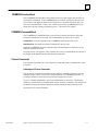
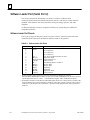
How to Make the System Work
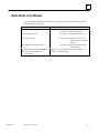
There are only a few simple tasks required to get your Ethernet Communications System
working. These tasks are addressed in detail later in this manual.
1.
Install the Ethernet Interface into the Series 90-30 baseplate and connect it to the
network.
2.
Configure the Ethernet Interface using Logicmaster 90 Configuration software or
CIMPLICITY Control.
3.
Power up the Series 90-30 PLC, store the configuration, and power-up the PLC again.
4.
Add COMMREQ functions in your ladder program if you need client capability.
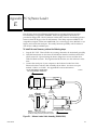
The figure below illustrates these tasks:
a45695
Series 90–30
PLC
User supplied
IBM PC
compatible
Ethernet Interface
Programming/Configuration software
Install
Programming/Configuration software
Use Configuration
package to create
interface
Install
Interface in PLC
Connect Interface
to Network
Power–up PLC
Use programmer
package to program
COMMREQs to initiate
communications from
your Series 90–70 PLC
Power–up PLC again
*
*Optional if client capability is needed
Fully
Operational
Interface
Figure 1-2. The Main Tasks for Installing the Ethernet Interface
1-4
TCP/IP Ethernet Communications User’s Manual – August 1997
GFK-1084B
1
Quick Guide to the Manual
The table below breaks down the tasks shown in Figure 1-2 and identifies where in the
manual they are described.
ÁÁÁÁÁÁÁÁÁÁÁÁÁÁÁÁÁÁÁÁÁÁÁÁÁÁÁÁÁ
ÁÁÁÁÁÁÁÁÁÁÁÁÁÁÁÁÁÁÁÁÁÁÁÁÁÁÁÁÁ
ÁÁÁÁÁÁÁÁÁÁÁÁ
ÁÁÁÁÁÁÁÁÁÁÁÁÁÁÁÁÁ
ÁÁÁÁÁÁÁÁÁÁÁÁ
ÁÁÁÁÁÁÁÁÁÁÁÁÁÁÁÁÁ
ÁÁÁÁÁÁÁÁÁÁÁÁÁÁÁÁÁÁÁÁÁÁÁÁÁÁÁÁÁ
ÁÁÁÁÁÁÁÁÁÁÁÁ
ÁÁÁÁÁÁÁÁÁÁÁÁÁÁÁÁÁ
ÁÁÁÁÁÁÁÁÁÁÁÁ
ÁÁÁÁÁÁÁÁÁÁÁÁÁÁÁÁÁÁÁÁÁÁÁÁÁÁÁÁÁ
ÁÁÁÁÁÁÁÁÁÁÁÁÁÁÁÁÁ
ÁÁÁÁÁÁÁÁÁÁÁÁÁÁÁÁÁÁÁÁÁÁÁÁÁÁÁÁÁ
ÁÁÁÁÁÁÁÁÁÁÁÁ
ÁÁÁÁÁÁÁÁÁÁÁÁÁÁÁÁÁ
ÁÁÁÁÁÁÁÁÁÁÁÁ
ÁÁÁÁÁÁÁÁÁÁÁÁÁÁÁÁÁ
ÁÁÁÁÁÁÁÁÁÁÁÁÁÁÁÁÁÁÁÁÁÁÁÁÁÁÁÁÁ
Tasks
Installing the Interface
Configuring the Interface
Procedure 2. Configuring the Interface
Powering-up the PLC
Procedure 3. Verifying Proper Power-Up
Operation of the Configured
Interface
PING Application Connection Tests
PLC Ladder Programming(COMMREQ)
Troubleshooting the Interface on
the Network
GFK-1084B
Where to go in the Manual
Chapter 2. Installing the Ethernet Interface
Procedure 1. Installing the Interface
Chapter 1 Introduction
Procedure 4. Pinging the TCP/IP Interfaces
on the Network
Chapter 3 ProgrammingCommunicationsRequests
Chapter 4. Troubleshooting
1-5
Chapter Installing the Ethernet Interface
2
This chapter describes the basic features of the Ethernet Interface, its installation, configuration, and a procedure for its initial checkout on your Ethernet cable. The chapter first
provides a hardware overview of the Ethernet Interface. It is then divided into four
Installation Procedures, each providing an overview of the procedure and then explaining the detailed steps to be performed.
As you work through a procedure you may encounter references to the appendices and
other chapters in this manual. These references provide more detailed information
about the subject under discussion.
The installation procedures described in this chapter are listed below:
H
H
H
H
Procedure 1: Mounting the Ethernet Interface on the PLC Baseplate - Required
Procedure 2: Configuring the Ethernet Interface - Required
Procedure 3: Verifying Proper Power-Up of the Ethernet Interface - Required
Procedure 4: “Pinging” the Ethernet Interfaces on the Network - Optional
Some of the procedures require prior Ethernet cable plant design and installation.
By completing the Installation Procedures you will gain an understanding of the parts of
the network and how they fit together. You will also have confidence that your equipment is working properly.
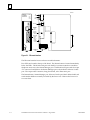
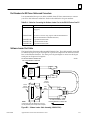
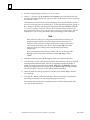
Ethernet Interface Hardware Overview
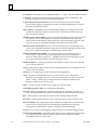
The Ethernet Interface is mounted on the Series 90-30 PLC baseplate. It is connected to
an Ethernet network via a user-provided transceiver cable and transceiver. The following figure shows the layout of the Ethernet Interface.
GFK-1084B
2-1
2
a45481c
CMM 321
ETHERNET
INTERFACE
OK
OK
LAN
LAN
SER
SER
STAT
STAT
RESTART
STATION
MANAGER
PORT
(PORT 1)
STATION
ADDRESS
LABEL
SOFTWARE
LOADER
PORT
(PORT 2)
SERIAL
NUMBER
LABEL
AAUI
TRANSCEIVER
PORT
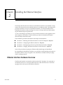
Figure 2-1. Ethernet Interface
The Ethernet Interface has several user-accessible elements.
Four LEDs are located at the top of the board. The Restart button is located immediately
below the LEDs. The RS-232 serial port with the RJ-11 connector (similar to a modular
telephone connector) is the Station Manager port. The RS-485 serial port with the 15-pin
“D” connector located below the Station Manager port is the module’s Software Loader
port. The 14-pin AAUI connector, facing downward, is the Transceiver port.
The Restart button, Station Manager port, Software Loader port, MAC address label, and
serial number label are normally concealed by the front cover. Remove the front cover
to access them.
2-2
TCP/IP Ethernet Communications User’s Manual - August 1997
GFK-1084B
2
Board Indicators
There are four LEDs on the Ethernet Interface: OK, LAN, SER, and STAT. Each of these
LEDs can be ON, OFF, BLINKING slow, or BLINKING fast. They indicate the state of the
Interface, traffic on the network port (LAN ONLINE LED), and that an exception event
has occurred.
All LEDs are briefly turned ON whenever the Restart button (described below) is released. This permits the operator to verify that all LEDs are operational.
See “Procedure 3. Verifying Proper Power-Up of the Ethernet Interface” for more LED
information.
Restart Button
The Restart button serves four functions: LED test, Restart, Restart and enter Software
Load state, and Restart and enter Maintenance state. These four functions behave similarly in all states except for the Software Load state. While in this state, pressing the button will cause an immediate restart into the Operational state if the software in the
Ethernet Interface has not been corrupted or erased. If the software has been corrupted
or erased, pressing the button will cause an immediate restart back into the Software
Load state. The following text describes Restart button behavior while not in the Software Load state.
Pressing the Restart button will disrupt communications.
LED Test: Any time the Restart button is released all the LEDs flash ON. The operator
should visually verify that all the LEDs go OFF and then ON at this time. Then the Interface performs either a restart, a restart and enter Software Load state, or a restart and
enter Maintenance state, depending on the duration that the operator depresses Restart.
Restart: Pressing the Restart button momentarily (less than 5 seconds) requests a restart
of the Ethernet Interface. When the Restart button is pressed, all LEDs go out. When it
is released, all LEDs flash ON, then power-up diagnostics run, and the software on the
Interface is restarted into the Operational state.
Restart and Enter Software Load State: Pressing and holding the Restart button for between 5 and 10 seconds forces a restart and requests entrance to the Software Load state.
A reload is used to install a software update into the module and is not part of normal
operation. When the Restart button is pressed, all LEDs go out. After 5 seconds have
elapsed, the STAT LED (bottom LED) comes ON, to indicate that the Ethernet Interface
will request a reload. After the Restart button is released, all LEDs flash ON, then power-up diagnostics run, and the Ethernet Interface waits to be loaded with all LEDs blinking in unison.
GFK-1084B
Chapter 2 Installing the Ethernet Interface
2-3
2
Notes
Reloading the Ethernet Interface requires the attachment of the PC
Software Loader to the Software Loader port and initiating a load with
the PC Software Loader. The PC Software Loader is a separate software
utility which updates the communications software in the Ethernet
Interface. This utility is supplied with any updates to the Ethernet
Interface software. See Appendix E for more information.
At any time before you initiate a load with the PC Software Loader, you
can restart the Ethernet Interface by pressing the Restart button.
Pressing this button will immediately cause the board to restart. If the
reload has been initiated, see Appendix E for more information.
Restart and Enter Maintenance State: Pressing and holding the Restart button for more
than 10 seconds forces a restart and requests entrance to the Maintenance state. Maintenance state must be invoked to change Advanced Parameters. While in Maintenance
state, all Advanced Parameters revert to their default value. When the Restart button is
pressed, all LEDs go out. After 5 seconds, the STAT LED comes ON, then after 10 seconds have elapsed, the STAT and SER LEDs both come ON, to indicate that the Ethernet Interface will request entry to the Maintenance state. After the Restart button is released, all LEDs flash ON then power-up diagnostics run and the Ethernet Interface
enters the Maintenance state.
Notes
In any case, any data being transferred by the Ethernet Interface at the
time of the Restart will be lost.
The Restart button is not operable during the diagnostic phase of
power-up. The Ethernet Interface is in diagnostic phase when the OK
LED is BLINKING fast and other LEDs are OFF.
Serial Ports
There are two serial ports on the Ethernet Interface: the Station Manager port (port 1)
and the Software Loader port (port 2).
The Station Manager Port
The 6-pin, RJ-11 “phone jack”, RS-232 port is used to connect a terminal or terminal
emulator to access the Station Manager software on the Ethernet Interface. A cable is
needed to connect the terminal or emulator to the Ethernet Interface (see Appendix B,
Communications Ports Characteristics).
The Software Loader Port
The 15-pin, D-type, RS-485 port is used to connect to the PC Software Loader in case the
communications software in the Ethernet Interface needs to be updated. The
characteristics of this port are given in Appendix B, Communications Ports
Characteristics.
2-4
TCP/IP Ethernet Communications User’s Manual - August 1997
GFK-1084B
2
AAUI (Transceiver) Port
The 14-pin AAUI port provides the electrical and mechanical interface to the user-provided IEEE 802.3 transceiver cable, which connects the AAUI Port to an external Ethernet-compatible transceiver (see Appendix B for the characteristics of the AAUI Port). The
external transceiver is directly connected to the Ethernet cable.
Default Station Address Label
The Default Station Address label lists the MAC address to be used by this Interface.
Serial Number Label
The Serial Number Label indicates the serial number of this Interface.
GFK-1084B
Chapter 2 Installing the Ethernet Interface
2-5
2
Procedure 1: Installing the Ethernet Interface in the PLC
This section describes the physical mounting of the Ethernet Interface onto the Series
90-30 PLC baseplate. For information on the installation procedures for the baseplate,
Series 90-30 CPU, Power Supply, and other Series 90-30 modules, refer to GFK-0356,
Series 90-30 Programmable Controller Installation Manual.
Equipment Required to Perform the Installation Procedures
In addition to the Ethernet Interface, make sure you have the items listed below before
you begin.
H
A Series 90-30 PLC CPU baseplate, or any Series 90-30 baseplate and a Series 90-30
CPU (version 5.03 or higher) with power supply.
H
An operating Logicmastert 90-30 system release 6.0 or higher, or CIMPLICITY
Control (runs on a personal computer).
H
An Ethernet-compatible AAUI transceiver and Ethernet cables. (See Appendix B for
more information.)
H
A serial cable for the Station Manager port on the Ethernet Interface (see Appendix
B). Optional
H
A terminal or IBM-compatible personal computer equipped with terminal emulation
software. Optional
Note
If your installation requires CE Mark compliance, please refer to
GFK-1179, Installation Requirements for Conformance to Standards, shipped
with the PLC programming software, for additional guidelines.
Ethernet Interface Installation
Use the following instructions as a guide when inserting a module into a slot in a
baseplate. These instructions assume that the power suppy on the baseplate is to your
left.
Warning
Do not insert or remove modules with power applied. This could cause
the PLC to Stop, damage the module, or result in personal injury.
2-6
1.
Be sure the Series 90-30 PLC baseplate power is OFF.
2.
Align the module with the desired base slot and connector. Tilt the module upwards
so that the top rear hook of the module engages the slot on baseplate.
3.
Swing the module downward until the connectors mate and the lock-lever on the
bottom of the module snaps into place engaging the baseplate notch.
TCP/IP Ethernet Communications User’s Manual - August 1997
GFK-1084B
2
4.
Visually inspect the module to be sure that it is properly seated.
5.
Remove the front cover of the Interface.
6.
Connect the transceiver cable into the 14-pin AAUI Port of the Ethernet Interface.
Secure the cable. The other end of the transceiver cable should be connected to an
external IEEE 802.3 compatible transceiver which is attached to the Ethernet
network. If the transceiver has a switch or jumper for SQE, it must be enabled. (Note:
The transceiver cable may be built-in to the transceiver or removable.)
7.
Replace the front cover and restore power to the baseplate.
8.
Use Logicmaster software, CIMPLICITY Control, or a Hand Held Programmer to
stop the CPU.
9.
Continue with Procedure 2: Configuring the Ethernet Interface.
Note
An Ethernet Interface can be mounted on a CPU baseplate, an
expansion baseplate, or a remote baseplate. However, due to power
requirements, only two Ethernet Interfaces are permitted per baseplate.
GFK-1084B
Chapter 2 Installing the Ethernet Interface
2-7
2
Procedure 2a: Configuring the Ethernet Interface with
Logicmaster 90-30 Configuration Software
Before you can use the Ethernet Interface with the Series 90-30 PLC, you must configure
the Interface using Logicmastert 90-30 configuration software or CIMPLICITYR Control (see Procedure 2b for configuring using CIMPLICITY Control). The Logicmaster
90-30 configuration software allows you to specify the modules and I/O that will reside
in your Series 90-30 PLC rack(s). The Hand Held Programmer may not be used to configure the Interface.
For the Ethernet Interface specifically, the configuration software allows you to:
H
H
Define the status address of the Ethernet Interface
H
Configure the serial ports (optional).
Assign the IP Address for the Ethernet Interface, and optionally the Subnet Mask
and the Gateway Address.
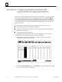
To configure the Ethernet Interface, access the I/O Configuration rack screen in the
Logicmaster 90-30 Configuration Package, and do the following:
2-8
1.
Move the cursor to the desired rack and slot location. The slot may be either
unconfigured or previously configured.
2.
Press the Communications softkey, i.e., Comm (F6). Your screen display will change
to the one shown on the following page.
TCP/IP Ethernet Communications User’s Manual - August 1997
GFK-1084B
2
GFK-1084B
3.
Press ethnet (F2). Your screen display will change to the one shown below.
4.
Press Enter to select the Ethernet Interface. You will then see the screen shown on
the following page.
Chapter 2 Installing the Ethernet Interface
2-9
2
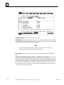
Configuration Mode: This is currently fixed as TCP/IP.
Status Address: The Status Address is the location of the LAN Interface Status (LIS) bits
(16 bits) and the Channel Status bits (64 bits). The Channel Status bits are always located
immediately following the LAN Interface Status bits.
Note
Do not use the 80-bits assigned to the LIS bits and Channel Status bits
for other purposes or your data will be overwritten.
Status Length: This is fixed at 80 bits (the sum of the LIS bits and the Channel Status
bits).
IP Address, Subnet Mask, Gateway Address, and Name Server IP Address: The values for
the IP Address, Subnet Mask, and Gateway Address should be assigned by the person in
charge of your network (the network administrator). TCP/IP network administrators are
familiar with these parameters. It is important that these parameters are correct, otherwise the Ethernet Interface may be unable to communicate on the network and/or network operation may be corrupted. It is especially important that each node on the network is assigned a unique IP address.
2-10
TCP/IP Ethernet Communications User’s Manual - August 1997
GFK-1084B
2
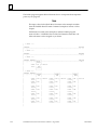
However, if you have no network administrator and a simple isolated network with no
gateways, you can use the following range of values for the assignment of local IP addresses:
3.0.0.1
3.0.0.2
3.0.0.3
.
.
.
3.0.0.255
First PLC
Second PLC
Third PLC
.
.
.
Logicmaster TCP or host
Also, on an isolated network, the Subnet Mask, Gateway IP address, and Name Server IP
address can all be 0.0.0.0. (The Name Server IP address is not currently used and is
reserved for future use.)
Note
If the isolated network is ever connected to another network, the IP
addresses 3.0.0.1 through 3.0.0.255 must not be used and the Subnet Mask
and Gateway IP address must be assigned by the Network Administrator.
The IP addresses must be assigned so that they are compatible with the
connected network. Refer to Appendix C for more information on
addressing.
See also the section “Determining If an IP Address Has Already Been
Used” in Procedure 4.
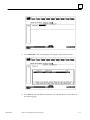
5.
GFK-1084B
Optionally, after you have assigned the IP address, etc., press Page Down to display
the following screen.
Chapter 2 Installing the Ethernet Interface
2-11
2
The Logicmaster 90-30 Configurator also allows you to optionally configure the Data
Rate, Parity, Stop Bits, Flow Control, Turn-around Delay, and Timeout for each of the two
serial ports (Station Manager Port and Software Loader Port. The defaults for both ports
are shown on the previous screen.
Data Rate: Data rate (bits per second or bps) for the port. Choices are 300, 600, 1200,
2400, 4800, 9600[, or 19200*.
Parity: Type of parity to be used for the port. Choices are NONE[, EVEN, or ODD*.
Stop Bits: Enter the number of stop bits. Choices are 1*[ or 2.
Flow Control: Type of flow control to be used for the port. Choices are HARDWARE or
NONE*[.
Turnaround Delay: Turnaround delay time to be used for the port. Choices are NONE*[,
10 ms, 100 ms, or 500 ms.
Timeout: Length of timeouts used for the port. Choices are LONG*[,
MEDIUM, SHORT, or NONE.
* Default selection for the Software Loader Port.
[ Default selection for the Station Manager Port
6.
Press the Escape key to return to the rack display. Press Escape again to save the
configuration to disk.
7.
Power up the PLC. (See Procedure 3 to verify proper power-up of the Ethernet
Interface.)
8.
Store the configuration to the PLC via the built-in serial port on the power supply.
Refer to GFK-0466, Logicmaster 90 Series 90-30/20/Micro Programming Software User’s
Manual for more information on configuring the Ethernet Interface using Logicmaster
90-30 software.
2-12
TCP/IP Ethernet Communications User’s Manual - August 1997
GFK-1084B
.
l-l2
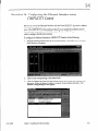
Procedure 2b: Configuring the Ethernet Interface using
COMPLICITY Control
Before you can use the Ethernet Interface with the Series 90-30 PLC, you must configure
the Interface using CIMPLCITY@ Control or Logicmaster TM90-30 configuration software. The CIMPLICITY Control software allows you to specify the modules and I/O
that will reside in your Series 90-30 PLC rack(s). The Hand Held Programmer can not be
used to configure the Ethernet Interface.
To configure the Ethernet Interface in CIMPLICITY
GFK1084B
Control, do the following:
1.
From the Browser, double-click
Rack Window will appear:
the 90-30 Rack System-Local
Rack icon. The Local
2.
Click the tab corresponding
3.
Click the desired slot, press the right mouse button, and choose Add Module from
the menu. (If the slot already contains a module, choose Replace Module.) The
Module Catalog dialog box will appear:
to the desired rack.
Chapter 2 lnstalling the Ethernet interface
2-13
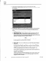
4.
In the Module Catalog dialog box, click the Communications tab, select
IC693CMM321 Ethernet Interface, then click the OK button. The Parameters dialog
box will appear:
5.
This dialog box will allow you to edit the module’s parameters. To edit a parameter
value, click in the appropriate Values field. The details of the Settings tab are as
follows:
l
l
Configuration Mode: This is currently fixed as TWII?
Status Reference Type: The Status Reference Type is the location of the LAN
Interface Status (LIS) bits (16 bits) and the Channel Status bits (64 bits). The
Channel Status bits are always located immediately following the LAN Interface
Status bits. The default is the next available %I address.
Note
Do not use the 80-bits assigned to the LIS bits and Channel Status bits
for other purposes or your data will be overwritten.
l
Status Length: This is fixed at 80 bits (the sum of the LIS bits and the Channel
Status bits).
l
IP Address, Subnet Mask, Gateway IP Address, and Name Server IP Address:
The values for the II’ Address, Subnet Mask, and Gateway Address should be
assigned by the person in charge of your network (the network administrator).
TCP/IP network administrators are familiar with these parameters. It is
important that these parameters are correct; otherwise, the Ethernet Interface
may be unable to communicate on the network and/or network operation may
be corrupted. It is especially important that each node on the network is
assigned a unique II’ address.
However, if you have no network administrator and are using a simple isolated
networkwith no gateways, you can use the following range of values for the
assignment of local II’ addresses:
2-14
TCP/lP Ethernet Communications
User’s Manual -August 1997
GFK-l084B
2
3.0.0.1
3.0.0.2
3.0.0.3
.
.
.
3.0.0.255
First PLC
Second PLC
Third PLC
.
.
.
Logicmaster TCP or host
On an isolated network, the Subnet Mask, Gateway IP address, and Name Server
IP address can all be 0.0.0.0.
Note
If the isolated network is ever connected to another network, the IP
addresses 3.0.0.1 through 3.0.0.255 must not be used and the Subnet Mask
and Gateway IP address must be assigned by the Network Administrator.
The IP addresses must be assigned so that they are compatible with the
connected network. Refer to Appendix C for more information on
addressing.
See also the section “Determining If an IP Address Has Already Been
Used” in Procedure 4.
D
Converter: Allows you to account for the power consumption added by a serial
port converter (measured in watts). Choices are 0, 0.500, and 0.600.
D AAUI Transceiver: Allows you to account for the power consumption added by
the AAUI Transceiver attached to the Ethernet module (measured in watts). The
valid range is 0.250 to 1.75.
6.
Optionally, after you have completed the Settings tab, you can configure parameters
for the Station Manager and Software Load ports by clicking the appropriate tab.
The details of the parameter settings for these ports are as follows:
D Data Rate: Data rate (bits per second or bps) for the port. Choices are 1200,
2400, 4800, 9600[, or 19200* .
D
Parity: Type of parity to be used for the port. Choices are None[, Even, or
Odd*.
D
Stop Bits: Enter the number of stop bits. Choices are 1*[ or 2.
D Flow Control: Type of flow control to be used for the port. Choices are
Hardware or None*[.
D Turnaround Delay: Turnaround delay time to be used for the port. Choices are
None* [, 10 ms, 100 ms, or 500 ms.
D
Timeout: Length of timeouts used for the port. Choices are Long*[, Medium,
Short, or None.
* Default selection for the Software Loader Port.
[ Default selection for the Station Manager Port
7.
GFK-1084B
If you want to assign variable names to specific points on the Ethernet card, click the
Point Reference tab. To assign a variable to a point, double-click the reference
address you want. The Insert Variable dialog box will appear, which will allow you to
fill in a variable name and description.
Chapter 2 Installing the Ethernet Interface
2-15
02
8.
If you want to view the power consumption of this module, click the Power
Consumption tab. After you have configured all of the module’s applicable
parameters, click the OK button. The module will now appear in the selected slot:
Refer to GFK- 1295, Using CIMPLlCHY
CIMPLICITY Control 90-30 software.
2-16
TCP/lP Ethernet Communications
Control, for more information
UserS Manual -August 1997
on using
GFK1084B
2
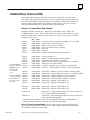
Procedure 3: Verifying Proper Power-Up of the Ethernet Interface
Powering-up the Ethernet Interface
After configuring the Interface as explained in Procedure 2, follow the procedure below
to verify that the Ethernet Interface is operating correctly.
1.
Turn power OFF to the PLC for 3–5 seconds, then turn the power back ON. This
will initiate a series of diagnostic tests.
The OK LED will blink indicating the progress of power-up.
2.
The LEDs will have the following pattern upon successful power-up. At this time
the Ethernet Interface is fully operational and on-line.
ÁÁÁÁÁÁÁÁÁÁÁÁÁÁÁÁ
ÁÁÁÁÁÁÁÁÁÁÁÁÁÁÁÁ
F
ÁÁÁÁÁÁÁÁÁÁÁÁÁÁÁÁ
F:
ÁÁÁÁÁÁÁÁÁÁÁÁÁÁÁÁ
`
ÁÁÁÁÁÁ
ÁÁÁÁÁÁÁÁÁÁ
F
ÁÁÁÁÁÁÁÁÁÁÁÁÁÁÁÁ
LED
OK
LAN
SER
STAT
Ethernet Interface Online
(On)
/
(On/Traffic)
(Off)
(On)
If STAT LED is OFF, check the PLC Fault Table. Alternatively,
use the Station Manager LOG command as explained in
GFK-1186, TCP/IP Ethernet Communications Station Manager
Manual.
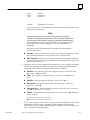
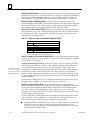
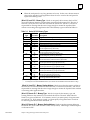
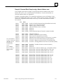
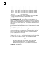
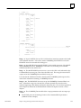
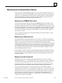
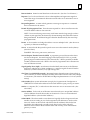
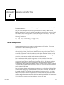
Problems During Power-up
If a problem is detected during power-up, the Ethernet Interface may not transition directly to the Operational State. If the Interface does not transistion to Operational, check
the LED pattern on the Interface and refer to Figure 2-2 to find out where the Interface
stopped. Refer to Table 2-1 for corrective actions.
GFK-1084B
Chapter 2 Installing the Ethernet Interface
2-17
2
L
`
`
`
The Ethernet Interface is initialized by
– Powering-up the PLC
– Storing a new configuration to the PLC with changes for the Ethernet Interface
– Pressing the Restart button
– Issuing a Station Manager RESTART, LOAD, or MAINT command
– Internal System Error occurring when Interface is Operational
Ethernet Interface
Initializing
(approx. 10 seconds)
Diagnostics
Pass?
No
A
`
`
`
`
Hardware
Failure
l
l
l
l
Software
Load
Yes
Load
Request or
Software
Corrupted?
Yes
B
Load Request Caused By
– Restart Pushbutton pushed for 5–10 seconds
– Station Manager LOAD command issued
– Detection of corrupt software
No
l
`
`
`
C
Waiting for
Configuration from
PLC CPU
(max. 2 minutes)
Done
Yes
IP address =
0.0.0.0
`
l
No
Maintenance
Request or
Fatal System
Error?
l
F/:/`
D
Waiting for IP Address Caused By
– Not configuring Interface using Logicmaster 90
– Configuring Interface with IP address = 0.0.0.0
– New CPU with no configuration
– CPU failure to communicate with Interface
Waiting for
IP Address
Continue to Maintenance or Operational Caused By
– IP address received from network BOOTP server
– IP address entered by BOOTP Station Manager command
IP Address Received
Yes
l
F/:/`
Fl/`
E
Maintenance Request Caused By
Maintenance
– Restart Pushbutton pushed for more than 10 seconds
– Station Manager MAINT command issued
– Fatal System Error while in Operational State forced
a restart
Symbols
No
F
F/:/`
`
F/`
F
Maintenance
– Client and server capability disabled
– Uses default Advanced Parameters
Operational
Operational
– Full support for client and server capability
– Uses user defined Advanced Parameters
The LEDs are labeled from top to bottom as follows:
OK
LAN
SER
STAT
The symbols used for the LEDs are defined as follows:
`
F
l
L
:
= OFF
= ON
= Slow Blink; multiple slow blinking LEDs
blink in unison
= Fast Blink
= Traffic (blinks when there is traffic on the line)
The process symbols are defined as follows:
= Temporary condition; requires no intervention
= Decision point during power-up
= Interface State; normally the Interface remains
in a State unless there is user intervention
Figure 2-2. States of the Ethernet Interface
2-18
TCP/IP Ethernet Communications User’s Manual - August 1997
GFK-1084B
2
ÁÁÁÁÁÁÁÁÁÁÁÁÁÁÁÁÁÁÁÁÁÁÁÁ
ÁÁÁÁÁÁÁÁÁÁÁ
ÁÁÁÁÁÁÁÁÁÁ
ÁÁÁÁÁ
ÁÁÁÁÁÁÁÁÁ
ÁÁÁÁÁÁÁÁÁÁÁ
H
`
`
H
ÁÁÁÁÁÁÁÁÁÁ
ÁÁÁÁÁ
ÁÁÁÁÁÁÁÁÁ
ÁÁÁÁÁÁÁÁÁÁÁ
`
H
ÁÁÁÁÁÁÁÁÁÁ
ÁÁÁÁÁ
ÁÁÁÁÁÁÁÁÁ
ÁÁÁÁÁÁÁÁÁÁÁ
`
H
ÁÁÁÁÁÁÁÁÁÁÁÁÁÁÁÁÁÁÁÁÁÁÁÁ
ÁÁÁÁÁÁÁÁÁÁÁ
ÁÁÁÁÁÁÁÁÁÁ
ÁÁÁÁÁ
ÁÁÁÁÁÁÁÁÁ
ÁÁÁÁÁÁÁÁÁÁÁ
H
H
ÁÁÁÁÁÁÁÁÁÁ
ÁÁÁÁÁ
ÁÁÁÁÁÁÁÁÁ
ÁÁÁÁÁÁÁÁÁÁÁ
ÁÁÁÁÁÁÁÁÁÁ
ÁÁÁÁÁ
ÁÁÁÁÁÁÁÁÁ
ÁÁÁÁÁÁÁÁÁÁÁ
H
H
l
l
ÁÁÁÁÁÁÁÁÁÁ
ÁÁÁÁÁ
ÁÁÁÁÁÁÁÁÁ
ÁÁÁÁÁÁÁÁÁÁÁ
l
H
ÁÁÁÁÁÁÁÁÁÁ
ÁÁÁÁÁ
ÁÁÁÁÁÁÁÁÁ
ÁÁÁÁÁÁÁÁÁÁÁ
l
H
ÁÁÁÁÁÁÁÁÁÁ
ÁÁÁÁÁ
ÁÁÁÁÁÁÁÁÁ
ÁÁÁÁÁÁÁÁÁÁÁ
H
ÁÁÁÁÁÁÁÁÁÁ
ÁÁÁÁÁ
ÁÁÁÁÁÁÁÁÁ
ÁÁÁÁÁÁÁÁÁÁÁ
H
H
l
ÁÁÁÁÁÁÁÁÁÁ
ÁÁÁÁÁÁÁÁÁÁÁÁÁÁ
ÁÁÁÁÁÁÁÁÁÁÁ
`
H
ÁÁÁÁÁÁÁÁÁÁ
ÁÁÁÁÁÁÁÁÁÁÁÁÁÁ
ÁÁÁÁÁÁÁÁÁÁÁ
`
`
H
ÁÁÁÁÁÁÁÁÁÁ
ÁÁÁÁÁ
ÁÁÁÁÁÁÁÁÁ
ÁÁÁÁÁÁÁÁÁÁÁ
ÁÁÁÁÁÁÁÁÁÁ
ÁÁÁÁÁ
ÁÁÁÁÁÁÁÁÁ
ÁÁÁÁÁÁÁÁÁÁÁ
H
ÁÁÁÁÁÁÁÁÁÁ
ÁÁÁÁÁ
ÁÁÁÁÁÁÁÁÁ
ÁÁÁÁÁÁÁÁÁÁÁ
H
H
ÁÁÁÁÁÁÁÁÁÁ
ÁÁÁÁÁ
ÁÁÁÁÁÁÁÁÁ
ÁÁÁÁÁÁÁÁÁÁÁ
H
l
F
:
`
ÁÁÁÁÁÁÁÁÁÁ
ÁÁÁÁÁ
ÁÁÁÁÁÁÁÁÁ
ÁÁÁÁÁÁÁÁÁÁÁ
`
H
l
ÁÁÁÁÁÁÁÁÁÁ
ÁÁÁÁÁ
ÁÁÁÁÁÁÁÁÁ
ÁÁÁÁÁÁÁÁÁÁÁ
ÁÁÁÁÁÁÁÁÁÁ
ÁÁÁÁÁ
ÁÁÁÁÁÁÁÁÁ
ÁÁÁÁÁÁÁÁÁÁÁ
ÁÁÁÁÁÁÁÁÁÁ
ÁÁÁÁÁ
ÁÁÁÁÁÁÁÁÁ
ÁÁÁÁÁÁÁÁÁÁÁ
H
H
l
F
:
`
ÁÁÁÁÁÁÁÁÁÁ
ÁÁÁÁÁ
ÁÁÁÁÁÁÁÁÁ
ÁÁÁÁÁÁÁÁÁÁÁ
l
ÁÁÁÁÁÁÁÁÁÁ
F`
ÁÁÁÁÁ
ÁÁÁÁÁÁÁÁÁ
ÁÁÁÁÁÁÁÁÁÁÁ
H
H
ÁÁÁÁÁÁÁÁÁÁ
ÁÁÁÁÁ
ÁÁÁÁÁÁÁÁÁ
ÁÁÁÁÁÁÁÁÁÁÁ
H
H
ÁÁÁÁÁÁÁÁÁÁ
ÁÁÁÁÁ
ÁÁÁÁÁÁÁÁÁ
ÁÁÁÁÁÁÁÁÁÁÁ
ÁÁÁÁÁÁÁÁÁÁ
ÁÁÁÁÁ
ÁÁÁÁÁÁÁÁÁ
ÁÁÁÁÁÁÁÁÁÁÁ
ÁÁÁÁÁÁÁÁÁÁ
ÁÁÁÁÁ
ÁÁÁÁÁÁÁÁÁ
ÁÁÁÁÁÁÁÁÁÁÁ
F
ÁÁÁÁÁÁÁÁÁÁ
ÁÁÁÁÁ
ÁÁÁÁÁÁÁÁÁ
ÁÁÁÁÁÁÁÁÁÁÁ
F:`
`
H
H
ÁÁÁÁÁÁÁÁÁÁ
ÁÁÁÁÁ
ÁÁÁÁÁÁÁÁÁ
ÁÁÁÁÁÁÁÁÁÁÁ
F`
ÁÁÁÁÁÁÁÁÁÁ
ÁÁÁÁÁ
ÁÁÁÁÁÁÁÁÁ
ÁÁÁÁÁÁÁÁÁÁÁ
H
ÁÁÁÁÁÁÁÁÁÁ
ÁÁÁÁÁ
ÁÁÁÁÁÁÁÁÁ
ÁÁÁÁÁÁÁÁÁÁÁ
H
ÁÁÁÁÁÁÁÁÁÁ
ÁÁÁÁÁ
ÁÁÁÁÁÁÁÁÁ
ÁÁÁÁÁÁÁÁÁÁÁ
H
ÁÁÁÁÁÁÁÁÁÁ
ÁÁÁÁÁ
ÁÁÁÁÁÁÁÁÁ
ÁÁÁÁÁÁÁÁÁÁÁ
H
ÁÁÁÁÁÁÁÁÁÁ
ÁÁÁÁÁ
ÁÁÁÁÁÁÁÁÁ
ÁÁÁÁÁÁÁÁÁÁÁ
ÁÁÁÁÁÁÁÁÁÁ
ÁÁÁÁÁ
ÁÁÁÁÁÁÁÁÁ
ÁÁÁÁÁÁÁÁÁÁÁ
H
ÁÁÁÁÁÁÁÁÁÁ
ÁÁÁÁÁ
ÁÁÁÁÁÁÁÁÁ
ÁÁÁÁÁÁÁÁÁÁÁ
ÁÁÁÁÁÁÁÁÁÁÁÁÁÁÁÁÁÁÁÁÁÁÁÁ
ÁÁÁÁÁÁÁÁÁÁÁ
Table 2-1. Problems During Power-Up
LED Pattern
OK (Off)
LAN (Off)
SER (Off)
STAT (Off)
OK (Slowblink)
LAN (Slowblink)
SER (Slowblink)
STAT (Slowblink)
Where Stopped
A
Hardware
Failure
B
Software
Loader
Restart button pressed
for 5–10 seconds.
Station Manager LOAD
command issued.
Software corrupt.
All LEDs blink in unison.
OK (Slow blink)
LAN (Off)
SER (Off)
STAT (Off)
PossibleCause
Fatal Hardware Error.
C
Did not configure slot.
Waiting for
Configuration
from PLC
New CPU with no
configuration.
(Condition can last a maximum of 2 minutes.)
Corrective Actions
Make sure the PLC has power.
Examine PLC Fault Table for clues.*
Recheck configuration.
Power off baseplate, inspect the
Interface for loose components,
reseat the Interface, and Restart.
Try a different slot.
If the problem persists, replace the
Interface or PLC hardware.
Connect a PC Software Loader and
load new software. See Appendix
E.
Cycle power or press Restart
button again for less than 5 seconds
to restart the Interface and clear the
load request.
Use configuration software to
configure the Interface then store
the configuration to the PLC CPU.
Make sure Interface is in the correct
slot on the baseplate.
Power cycle the PLC.
OK (Slowblink)
/ / LAN (On/T
raffic/Off)
SER (Off/Slowblink)
STAT (Slowblink)
OK and STAT blink in unison.
OK (Slowblink)
/ / LAN (On/T
raffic/Off)
SER (Slow blink)
/ STAT (On/Off)
D
Waiting for IP
Address
E
Maintenance
OK and SER blink in unison.
/ /
/
OK (On)
LAN (On/Traffic/Off)
SER (Off)
STAT (On/Off)
F
Operational
PLC in STOP/FAULT.
Clear faults and reset Interface.
Interface’s IP address has
not been configured or has
been configured as 0.0.0.0.
Configure the Interface with a
non-zero IP address.
Restart button pressed
for more than 10
seconds.
Station Manager MAINT
command issued.
Internal System Error
when Interface was
Operational caused a
restart and entrance into
Maintenance.
If the LAN LED is Off, the
problem may be:
Transceiver not
connected to Interface or
tranceiver not connected
to Ethernet cable or bad
transceiver.
Network cable not
terminated properly.
Use a BOOTP server to provide
Interface with a non-zero IP
address.
If you did not intend to enter
Maintenance press the Restart
button for less than 5 seconds. This
clears the Maintenance request.
Examine PLC Fault Table for clues.*
If you need to use the Station
Manager to troubleshoot a
problem, see GFK-1186,TCP/IP
Ethernet Communications Station
Manager Manual.
Connect cable and transceiver
properly. Replace transceiver.
Terminate network cable properly.
Set SQE ON on transceiver in
accord with manufacturer’s
instructions.
SQE not enabled on
transceiver.
If the STAT LED is Off, an
exception condition has occurred.
Examine PLC Fault Table to find
out why the STAT LED is Off. *
* Identify the PLC fault message using Logicmaster 90 or CIMPLICITY Control then refer to Table 4-1 in Chapter 4,
Troubleshooting, for corrective actions.
GFK-1084B
Chapter 2 Installing the Ethernet Interface
2-19
2
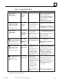
Procedure 4: Pinging TCP/IP Ethernet Interfaces on the Network
PING (Packet InterNet Grouper) is the name of a program used on TCP/IP networks to
test reachability of destinations by sending them an ICMP echo request message and
waiting for a reply. Most nodes on TCP/IP networks, including the Series 90-30 Ethernet
Interface, implement a PING command.
The user should ping each installed Ethernet Interface. When the Ethernet Interface responds to the ping, it verifies that the interface is operational and configured properly.
Specifically it verifies that acceptable TCP/IP configuration information has been stored
to the Interface.
Pinging the Interface from a UNIX host or a PC Running TCP/IP
Software
t
The ping can be executed from a UNIX host or PC running TCP/IP (since most TCP/IP
communications software provides a ping command) or from another Ethernet Interface.
When using a PC or UNIX host, the user can refer to the documentation for the ping command, but in general all that is required is the IP address of the remote host as a parameter
to the ping command. For example, at the command prompt type:
ping
3.0.0.1
Determining If an IP Address Has Already Been Used
It is very important not to duplicate IP addresses. To determine if you have configured your
Ethernet Interface with the same IP address as another node:
2-20
1.
Disconnect your Interface from the LAN.
2.
Ping the disconnected Interface’s IP address. If you get an answer to the ping, then
the chosen IP address is already in use by another node. You must correct this
situation by assigning unique IP addresses.
TCP/IP Ethernet Communications User’s Manual - August 1997
GFK-1084B
Chapter Programming Communications Requests
3
This chapter describes how to program PLC to PLC communications over the Ethernet
Network. Details of the COMMREQ function and the Channel commands are presented here. The chapter is divided into 5 sections:
H
H
H
H
H
Section 1: The Communications Request
Section 2: The COMMREQ Function Block and Command Block
Section 3: Channel Commands
Section 4: Status Data
Section 5: Controlling Communications in the Ladder Program
Note
This chapter applies only to PLCs being used as client PLCs to initiate
communications. No programming is required for server operation.
GFK-1084B
3-1
3
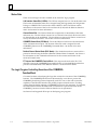
Section 1: The Communications Request
“Communications Request” is a term used to describe all the user elements required for
correctly initiating Channel Commands from a Series 90 PLC. This section describes the
elements of the Communications Request.
No programming of Communications Requests is required for PLCs acting as servers
which are merely targets of other systems’ requests but do not themselves initiate requests.
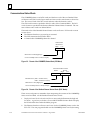
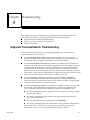
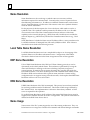
Structure of the Communications Request
The Communications Request is made up of the following elements.
H
H
H
H
The COMMREQ Function Block (ladder instruction)
H
The logic program controlling execution of the COMMREQ Function Block
The COMMREQ Command Block
The Channel Command
Status Data (COMMREQ Status word, LAN Interface Status and Channel Status
bits)
The figure below illustrates the relationship of these elements:
CONTROL
LOGIC
INITIATES
COMMREQ
FUNCTION
BLOCK
COMMREQ
FUNCTION BLOCK
INPUTS
AND
OUTPUTS
FOR COMMREQ
FUNCTION
COMMAND
BLOCK
POINTER
COMMREQ
COMMAND BLOCK
COMMREQ
STATUS
WORD
POINTER
DETAILS
OF THE
CHANNEL
COMMAND
COMMREQ
STATUS WORD
STATUS
CODES
STATUS BITS
LAN INTERFACE STATUS
AND CHANNEL STATUS
BITS
Location in PLC memory specified when configuring the Interface using Configuration
Software
Figure 3-1. Elements of the Communications Request
3-2
TCP/IP Ethernet Communications User’s Manual - August 1997
GFK-1084B
3
COMMREQ Function Block
The COMMREQ Function Block is the ladder instruction that triggers the execution of
the Channel Command. In the COMMREQ Function Block, you specify the rack and
slot location of the Ethernet Interface and a pointer to a location in memory that contains the Command Block. There is also a fault output on the COMMREQ Function
Block that indicates certain programming errors. See Section 2 for details.
COMMREQ Command Block
The COMMREQ Command Block is a structure that contains information about the
Channel Command to be executed. The Command Block consists of two parts:
Common Area - includes a pointer to the COMMREQ Status word (CRS word)
Data Block Area - describes the Channel Command to be executed.
When the COMMREQ function is initiated, the Command Block is transferred to the
Ethernet Interface for action.
See Section 2 for a description of the common area of the Command Block and Section 3
for details on the Data Block area and Channel Commands.
Channel Commands
The Channel Commands are a set of client PLC commands used to communicate with a
server PLC.
Advantages of Channel Commands
The advantage of Channel Commands is their ability to establish a channel to execute
multiple periodic reads or writes-with a single initiation of a COMMREQ function. A
Channel Command can also be used to execute a single read or write.
Up to 16 channels (numbered 1-16) can be established by a client PLC. The channel
number is specified in the Command Block for the Channel Command. The channel can
be monitored using the Channel Status bits and the Detailed Channel Status words.
See Section 3 for more information.
GFK-1084B
Chapter 3 Programming Communications Requests
3-3
3
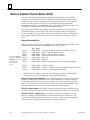
Status Data
There are several types of status available to the client PLC logic program.
LAN Interface Status Bits (LIS Bits): The LIS bits comprise bits 1-16 of an 80-bit status area.
The location of this 80-bit status area is assigned using the Logicmaster 90 Configuration
Package or CIMPLICITY Control in the “Status Address” field. The LIS bits contain
information on the status of the Local Area Network (LAN) and the Ethernet Interface
itself. See Section 4 for more information.
Channel Status Bits: The Channel Status bits comprise bits 17-80 (64 bits) of the status
indication area. The first 32 bits consist of an error bit and a data transfer bit for each of the
16 channels that can be established. The last 32 bits are reserved for future use and set to
zero by the Ethernet Interface. See Section 4 for more information.
COMMREQ Status Word (CRS Word): The 16-bit CRS word will receive the initial status
of the communication request. The location of the CRS word is assigned for each
COMMREQ function in the COMMREQ Command Block. See Section 4 for more
information.
Detailed Channel Status Words (DCS Words): This detailed status data is retrieved for a
particular channel using the Retrieve Detailed Channel Status Command. See Section 3
for information on the command and Section 4 for the contents and format of the
retrieved channel status.
FT Output of the COMMREQ Function Block: This output indicates that the PLC CPU
detected errors in the COMMREQ Function Block and/or Command Block and did not
pass the Command Block to the Ethernet Interface. See Section 4 for details.
The Logic Program Controlling Execution of the COMMREQ
Function Block
Care must be taken in developing the logic that controls the execution of the COMMREQ
function. The COMMREQ function must be initiated by a one-shot to prevent the
COMMREQ from being executed repeatedly each CPU scan, as this will overrun the
capability of the Ethernet Interface and possibly require a manual restart. Checking
certain status bits before initiating a COMMREQ function is also important. In particular,
the LAN Interface OK bit should be used as an interlock to prevent execution of the
COMMREQ function when the Ethernet Interface is not operational.
See Section 5 and Appendix D for tips on developing your program.
3-4
TCP/IP Ethernet Communications User’s Manual - August 1997
GFK-1084B
3
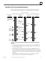
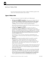
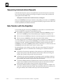
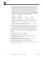
Operation of the Communications Request
The figure and text below explains how a Communications Request is executed. The
figure specifically illustrates the operation of an Establish Read Channel Command.
Domain of a TCP connection
Domain of a remote server
Domain of a channel
Client
Series 90–70
PLC CPU
Client
Ethernet
Interface
Backplane
LAN
Server
Ethernet Interface
Backplane
Server
CPU
Power flows to COMMREQ
in ladder program
Command Block sent to
Interface
Verify
Command Block
and set up channel
to server PLC
Read Request
Read Request
Data
Data
Data
Data
COMMREQ
Status Word
Data Transfer
pulse received
Return COMMREQ
Status (CRS) Word
to CPU
Pulse Data Transfer bit
Read Request
Data
Data
Read Request
Data
Data
Pulse Data Transfer bit
Data Transfer
pulse received
.
.
.
.
.
.
Read Request
Data
Data
Data Transfer
pulse received
Read Request
Data
Data
Pulse Data Transfer bit
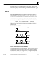
Figure 3-2. Operation of the Communications Request for an Establish Read ChannelCommand
1.
A Communications Request begins when there is power flow to a COMMREQ function in the client PLC. At this time, the Command Block data is sent from the PLC
CPU to the Ethernet Interface.
2.
For the Establish Read Channel Channel command, the COMMREQ Status word
(CRS word) is returned immediately if the Command Block is invalid. If the syntax is
correct, then the CRS word is returned after the first significant event: upon failure to
establish a channel correctly and in a timely manner or upon the first successful transfer of data.
Once the channel is successfully set up to the server PLC, the Ethernet Interface
performs the periodic reads as specified in the Command Block.
GFK-1084B
Chapter 3 Programming Communications Requests
3-5
3
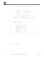
Section 2: The COMMREQ Function Block and Command Block
This section describes the programming structures common to all Communications
Requests: the COMMREQ Function Block and the Command Block.
The COMMREQ Function Block
The Communications Request is triggered when the logic program passes power to the
COMMREQ Function Block. For the Series 90-30 PLC, the COMMREQ Function Block
has four inputs and two outputs:
(Enable )
––––––––––––––
COMM
REQ
(Command Block Pointer)
–
(Rack/SlotLocationof
the Ethernet Interface)
–
SYSID
00000000 –
TASK
(Alwayszero)
IN
FT
– Function Faulted(logic)
Each of the inputs and the output are discussed in detail below. It is important to understand that the Command Block pointer points to the location in memory you are using
for the Command Block.
Enable: Control logic for activating the COMMREQ Function Block. See Section 5 and
Appendix D for tips on developing your program.
IN: The location of the Command Block. It may be any valid address within a word-oriented area of memory (%R, %AI, %AQ, %P, or %L).
SYSID: A hexadecimal value that gives the rack (high byte) and slot (low byte) location
of the Ethernet Interface.
Examples:
3-6
Rack
Slot
Hex Word Value
0
4
0004h
3
4
0304h
2
9
0209h
4
2
0402h
TCP/IP Ethernet Communications User’s Manual - August 1997
GFK-1084B
3
TASK: This must always be set to zero for the Ethernet Interface
Caution
Entering a number other than zero for TASK may cause the Ethernet Interface to
fail.
FT Output: The FT output is set if the PLC (rather than the Ethernet Interface) detects
that the COMMREQ fails. In this case, the other status indicators are not updated for
this COMMREQ. See Section 3 for more information.
The COMMREQ Command Block
When the COMMREQ function is initiated, the Command Block is sent from the PLC
CPU to the Ethernet Interface. The Command Block contains the details of a Channel
Command to be performed by the Interface.
The address in CPU memory of the Command Block is specified by the IN input of the
COMMREQ Function Block. This address may be in any word-oriented area of memory
(%R, %AI, or %AQ). The Command Block is set up using an appropriate programming
instruction (the BLOCK MOVE Function Block is recommended).
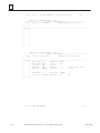
The Command Block has the following structure:
ÁÁÁÁÁÁÁÁÁÁÁÁÁÁÁÁÁÁÁÁ
ÁÁÁÁÁÁÁÁÁÁÁÁÁÁÁÁÁÁÁÁ
ÁÁÁÁÁÁ
ÁÁÁÁÁÁÁÁÁÁÁÁÁÁÁÁÁÁÁÁ
ÁÁÁÁÁÁÁÁÁÁÁÁÁÁ
ÁÁÁÁÁÁÁÁÁÁÁÁÁÁÁÁÁÁÁÁ
ÁÁÁÁÁÁÁÁÁÁÁÁÁÁÁÁÁÁÁÁ
ÁÁÁÁÁÁ
ÁÁÁÁÁÁÁÁÁÁÁÁÁÁ
ÁÁÁÁÁÁÁÁÁÁÁÁÁÁÁÁÁÁÁÁ
Word 1
Data Block Length (words)
Word 2
WAIT/NOWAIT Flag = 0
Word 3
CRS Word Pointer Memory Type
Word 4
CRS Word Pointer Offset
Word 5
Reserved
Word 6
Reserved
Words 7 and up
Data Block (Channel Command Details)
When entering information for the Command Block, refer to these definitions:
(Word 1) Data Block Length: This is the length in words of the Data Block portion of the
Command Block. The Data Block portion starts at Word 7 of the Command Block. The
length is measured from the beginning of the Data Block at Word 7, not from the beginning of the Command Block. The correct value for each command, and the associated
length of each command, is specified in Section 3.
(Word 2) WAIT/NOWAIT Flag: This flag must be set to zero for TCP/IP Ethernet Communications.
GFK-1084B
Chapter 3 Programming Communications Requests
3-7
3
COMMREQ Status Word: The Ethernet Interface updates the CRS word to show success
or failure of the command. Command words 3 and 4 specify the PLC memory location
of the CRS word.
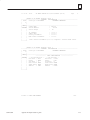
(Word 3) COMMREQ Status Word Pointer Memory Type: This word specifies the memory
ÁÁÁÁÁ
ÁÁÁÁ
ÁÁÁÁÁ
ÁÁÁÁÁÁÁÁÁÁÁÁÁÁÁÁ
ÁÁÁÁÁÁÁÁÁÁÁÁÁÁÁÁÁÁÁÁÁÁÁÁÁÁÁÁÁÁ
ÁÁÁÁÁÁÁÁÁÁÁÁÁÁÁÁÁÁÁÁÁÁÁÁÁÁÁÁÁÁ
ÁÁÁÁÁÁÁÁÁÁÁÁÁÁÁÁÁÁÁÁÁÁÁÁÁÁÁÁÁÁ
ÁÁÁÁÁ
ÁÁÁÁ
ÁÁÁÁÁ
ÁÁÁÁÁÁÁÁÁÁÁÁÁÁÁÁ
ÁÁÁÁÁÁÁÁÁÁÁÁÁÁÁÁÁÁÁÁÁÁÁÁÁÁÁÁÁÁ
ÁÁÁÁÁ
ÁÁÁÁ
ÁÁÁÁÁ
ÁÁÁÁÁÁÁÁÁÁÁÁÁÁÁÁ
ÁÁÁÁÁ
ÁÁÁÁÁÁÁÁÁ
ÁÁÁÁÁÁÁÁÁ
ÁÁÁÁÁÁÁÁÁÁÁÁÁÁÁÁÁÁÁÁÁ
ÁÁÁÁÁÁÁÁÁÁÁÁÁÁÁÁ
ÁÁÁÁÁ
ÁÁÁÁ
ÁÁÁÁÁ
ÁÁÁÁÁÁÁÁÁÁÁÁÁÁÁÁ
ÁÁÁÁÁÁÁÁÁÁÁÁÁÁÁÁÁÁÁÁÁÁÁÁÁÁÁÁÁÁ
ÁÁÁÁÁ
ÁÁÁÁ
ÁÁÁÁÁ
ÁÁÁÁÁÁÁÁÁÁÁÁÁÁÁÁ
ÁÁÁÁÁ
ÁÁÁÁ
ÁÁÁÁÁ
ÁÁÁÁÁÁÁÁÁÁÁÁÁÁÁÁ
ÁÁÁÁÁÁÁÁÁÁÁÁÁÁÁÁÁÁÁÁÁÁÁÁÁÁÁÁÁÁ
type for the CRS word. The memory types are listed in the table below.
Type
%R
%AI
%AQ
%I
%Q
%T
%M
%G
Value
(Decimal)
8
10
12
16
70
18
72
20
74
22
76
56
86
Value
(Hex.)
08h
0Ah
0Ch
10h
46h
12h
48h
14h
4Ah
16h
4Ch
38h
56h
Description
Register memory (word mode)
Analog input memory (word mode)
Analog output memory (word mode)
Discrete input memory (byte mode)
Discrete input memory (bit mode)
Discrete output memory (byte mode)
Discrete output memory (bit mode)
Discrete temporary memory (byte mode)
Discrete temporary memory (bit mode)
Discrete momentary internal memory (byte mode)
Discrete momentary internal memory (bit mode)
Discrete global data table (byte mode)
Discrete global data table (bit mode)
(Word 4) COMMREQ Status Word Pointer Offset: This word contains the offset within
the memory type selected. The status word pointer offset is a zero-based number. For example, if you want %R1 as the location of the CRS word, you must specify a zero for the
offset. The offset for %R100 would be 99. Note, however, that this is the only zerobased field in the Channel commands.
For information on the contents of the COMMREQ Status word, see Section 4.
(Word 5): Reserved. Set to zero.
(Word 6): Reserved. Set to zero.
(Words 7 and up) Data Block: The Data Block defines the Channel command to be performed. For information on how to fill in the Channel command information, see Section 3.
3-8
TCP/IP Ethernet Communications User’s Manual - August 1997
GFK-1084B
3
Section 3: Channel Commands
This section describes the Channel Commands. A detailed description and example of
each channel command is included. There are five Channel Commands.
1.
Establish Read Channel
2.
Establish Write Channel
3.
Send Information Report
4.
Abort Channel
5.
Retrieve Detailed Channel Status
Establishing a Channel
The Ethernet Interface transfers data to or from another PLC using a channel. There are
two channel commands for transferring data between PLCs.
H
H
Establish Read Channel
Establish Write Channel
The Ethernet Interface also transfers data to a host, another computer on the network,
which is running Host Communications Toolkit (HCT) software. There is one channel
command for transferring data to a host computer.
H
Send Information Report
These Channel Commands are based on the concept of periodic data transfers. The
client (local) PLC uses a single COMMREQ function to establish a channel (connection)
to a server (remote) PLC and to request that specific data be periodically transferred
between the PLCs.
Note
To simplify the discussion of the Command Blocks, we make the
assumption that the operator/programmer is local to the client PLC and
the server is remote from this operator/programmer.
The Ethernet Interface automatically manages the establishment of communications and
the periodic data transfer. Parameters in the Command Block specify the frequency and
direction of the transfer, and the memory locations in the client and server to be used in
the transfer.
Aborting and Re-tasking a Channel
There are four ways a channel can be aborted.
GFK-1084B
1.
When the PLC CPU is stopped, all channels in use are aborted.
2.
A channel (or all channels) can be aborted by issuing an Abort Channel command.
3.
A channel in use can be re-tasked by issuing an establish command for its channel
number. This aborts the previous channel operation and then performs the new
channel operation.
4.
A channel is also automatically aborted if a fatal error occurs.
Chapter 3 Programming Communications Requests
3-9
3
Retrieving Detailed Status on the Channel
As discussed before, there are several forms of status available to the ladder program.
These are all discussed in Section 4. One form of status is obtained through the Retrieve
Detailed Channel Status (RDCS) command described later in this section.
Specifying a Network Address
All establish commands must identify the remote server device with which data will be
transferred. The remote device may be specified in two ways: By IP address, or by a
name previously defined with the proper IP address. Examples of each network address
type are provided for all establish commands. (For further information on the use of
network address names, see Appendix F.)
3-10
TCP/IP Ethernet Communications User’s Manual - August 1997
GFK-1084B
3
Establish Read Channel (2003)
The Establish Read Channel Command requests that a channel be associated with a
remote PLC and that data from the remote PLC be transferred (periodically) to the local
PLC. The Command Block specifies the period, the number of reads from the remote to
perform, and the timeout allowed in waiting for each transfer to complete. The first
read is performed immediately, regardless of the period specified.
Example 1 Command Block–Basic Example
Establish a channel (channel 5) to a remote PLC at IP address 3.0.0.1. Return the
COMMREQ Status word to %R10. Read remote PLC registers %R50-%R57 to local PLC
registers %R100-%R107. Repeat the read 10 times once every 7 seconds with a timeout
of 500 ms for each read.
ÁÁÁÁÁÁÁÁÁÁÁÁÁÁÁÁÁÁÁÁÁÁÁÁÁÁÁÁÁÁ
ÁÁÁÁÁ
ÁÁÁÁÁÁÁÁÁÁÁ
ÁÁÁÁÁÁÁÁÁÁÁÁÁÁÁÁÁÁÁÁÁÁÁÁÁ
ÁÁÁÁÁÁÁÁÁÁÁÁÁÁÁÁÁÁÁ
ÁÁÁÁÁÁÁÁÁÁÁÁÁÁÁÁÁÁÁÁÁÁÁÁÁÁÁÁÁÁ
ÁÁÁÁÁÁÁÁÁÁÁÁÁÁÁÁÁÁÁÁÁÁÁÁÁÁÁÁÁÁ
ÁÁÁÁÁÁÁÁÁÁÁÁÁÁÁÁÁÁÁÁÁÁÁÁÁÁÁÁÁÁ
ÁÁÁÁÁÁÁÁÁÁÁÁÁÁÁÁÁÁÁÁÁÁÁÁÁÁÁÁÁÁ
ÁÁÁÁÁÁÁÁÁÁÁÁÁÁÁÁÁÁÁÁÁÁÁÁÁÁÁÁÁÁ
ÁÁÁÁÁÁÁÁÁÁÁÁÁÁÁÁÁÁÁÁÁÁÁÁÁÁÁÁÁÁ
ÁÁÁÁÁÁÁÁÁÁÁÁÁÁÁÁÁÁÁÁÁÁÁÁÁÁÁÁÁÁ
ÁÁÁÁÁÁÁÁÁÁÁÁÁÁÁÁÁÁÁÁÁÁÁÁÁÁÁÁÁÁ
ÁÁÁÁÁ
ÁÁÁÁÁÁÁÁÁÁÁ
ÁÁÁÁÁÁÁÁÁÁÁÁÁÁÁÁÁÁÁÁÁÁÁÁÁ
ÁÁÁÁÁÁÁÁÁÁÁÁÁÁÁÁÁÁÁ
ÁÁÁÁÁÁÁÁÁÁÁÁÁÁÁÁÁÁÁÁÁÁÁÁÁÁÁÁÁÁ
ÁÁÁÁÁÁÁÁÁÁÁÁÁÁÁÁÁÁÁÁÁÁÁÁÁÁÁÁÁÁ
ÁÁÁÁÁÁÁÁÁÁÁÁÁÁÁÁÁÁÁÁÁÁÁÁÁÁÁÁÁÁ
ÁÁÁÁÁÁÁÁÁÁÁÁÁÁÁÁÁÁÁÁÁÁÁÁÁÁÁÁÁÁ
ÁÁÁÁÁÁÁÁÁÁÁÁÁÁÁÁÁÁÁÁÁÁÁÁÁÁÁÁÁÁ
ÁÁÁÁÁ
ÁÁÁÁÁÁ
ÁÁÁÁÁÁÁÁÁÁÁÁÁÁÁÁÁÁÁ
ÁÁÁÁÁÁÁÁÁÁÁÁÁÁÁÁÁÁÁÁÁÁÁÁÁÁÁÁÁÁ
ÁÁÁÁÁÁÁÁÁÁÁÁÁÁÁÁÁÁÁÁÁÁÁÁÁÁÁÁÁÁ
ÁÁÁÁÁÁÁÁÁÁÁÁÁÁÁÁÁÁÁÁÁÁÁÁÁÁÁÁÁÁ
ÁÁÁÁÁÁÁÁÁÁÁÁÁÁÁÁÁÁÁÁÁÁÁÁÁÁÁÁÁÁ
ÁÁÁÁÁÁÁÁÁÁÁÁÁÁÁÁÁÁÁÁÁÁÁÁÁÁÁÁÁÁ
ÁÁÁÁÁ
ÁÁÁÁÁÁ
ÁÁÁÁÁÁÁÁÁÁÁÁÁÁÁÁÁÁÁ
ÁÁÁÁÁÁÁÁÁÁÁÁÁÁÁÁÁÁÁÁÁÁÁÁÁÁÁÁÁÁ
Word 1
Word 2
Word 3
Word 4
Word 5
Word 6
Word 7
Word 8
Word 9
Word 10
Word 11
The term local PLC is Word 12
used here to identify the Word 13
client PLC-the PLC
Word 14
that initiates the
communications
request.
Word 15
Word 16
The term remotePLC Word 17
is used here to identify Word 18
the server PLC-the
Word 19
PLC that responds to
Word 20
the request.
Word 21
Word 22
Word 23
Dec
00017
00000
00008
00009
00000
00000
02003
(Hex)
(0011)
(0000)
(0008)
(0009)
(0000)
(0000)
(07d3)
Length of Channel Command Data Block (17 - 25 words)
Always 0 (no-wait mode request)
Memory type of CRS word (%R)
CRS word address minus 1 (%R10)*
Reserved
Reserved
Establish Read Channel Command number
00005
00010
00003
00007
00050
00008
00100
(0005)
(000A)
(0003)
(0007)
(0032)
(0008)
(0064)
Channel number (5)
Number of read repetitions (read 10 times)
Time unit for read period (3=seconds)
Number of time units for read period (every 7 seconds)
Timeout for each read (500 ms)
Local PLC - Memory type at which to store data (%R)
Local PLC - Starting address at which to store data (%R100)
00008
00050
00008
00001
00004
00003
00000
(0008)
(0032)
(0008)
(0001)
(0004)
(0003)
(0000)
Remote PLC - Memory type from which to read data (%R)
Remote PLC - Starting address from which to read data (%R50)
Remote PLC - Number of memory units (8 registers)
Remote PLC - Network address type (IP Address)
Remote PLC - Network address length in words (4)
Remote PLC - Register 1 of IP address (3)
Remote PLC - Register 2 of IP address (0)
00000 (0000)
00001 (0001)
Remote PLC - Register 3 of IP address (0)
Remote PLC - Register 4 of IP address (1)
Word 24 - 27
Remote PLC - Program Name (needed for access to remote %P
or %L) (zero terminated and padded)
Word 28 - 31
Remote PLC - Program Block (needed for access to remote %L)
(zero terminated and padded)
* Word 4 (CRS word address) is the only zero-based address in the Command Block.
Only this address requires subtracting 1 from the intended address.
(Word 7) Channel Command Number: Word 7 requests that a read channel be set up. If
the command is processed successfully, it will result in attempting the specified number
of transfers from the server to the client.
GFK-1084B
Chapter 3 Programming Communications Requests
3-11
3
(Word 8) Channel Number: Word 8 specifies the channel to be used for the read. This value
must be in the range of 1 to 16. If the channel is out of range, a command error indication
will be placed in the COMMREQ Status word. If the channel number is the same as a
channel already in use, the channel will be retasked to perform this new command.
(Word 9) Number of Read Repetitions: Word 9 specifies the number of reads to be
performed before automatically completing the communications request and closing the
channel. If this value is set to 1, only a single read will be issued. If this value is set to 0,
reads will be issued on the requested period until the channel is aborted.
(Word 10) Time Unit for Read Period: Words 10-11 together define how often the read is
to be performed (read period). Word 10 specifies the time unit such as seconds or minutes
for the read period. Word 11 specifies the number of those units. The choices for the
time units are specified in Table 3-1.
ÁÁÁÁ
ÁÁÁÁÁÁÁÁÁÁÁÁÁÁÁÁ
ÁÁÁÁÁÁÁÁÁÁÁÁ
ÁÁÁÁÁÁÁÁÁÁÁÁÁÁÁÁ
ÁÁÁÁÁÁÁÁÁÁÁÁÁÁÁÁ
ÁÁÁÁ
ÁÁÁÁÁÁÁÁÁÁÁÁ
ÁÁÁÁÁÁÁÁÁÁÁÁÁÁÁÁ
Table 3-1. Time Unit Values for Read/Write Repetition Period
Value
Meaning
1
hundredths of seconds (10 ms)
2
tenths of seconds
(100 ms)
3
seconds
4
minutes
5
hours
Note: If Time Unit Value is 5 (hours), then the maximum
usable value of Number of Time Units is 5965.
(Word 11) Number of Time Units for Read Period: Word 11 specifies the number of time
units for the read period. The read period is in effect even when the Channel Command
is setup to issue a single read.
Example Read Period Calculation: If Word 10 contains a value of 3 specifying seconds
as the time unit and Word 11 contains a value of 20, then the read period is 20 seconds.
A Channel Command
set up to issue a single
read can have only one
pending read transfer.
A read will normally be issued at the start of each read period. If the pending read
transfer has not completed during the read period, the Channel Error bit and Detailed
Channel Status words will be set to indicate a non-fatal period error. The pending
transfer can still complete after the period error occurs. For Channel Commands set up
to issue multiple reads, the next read transfer will be issued only after the pending read
transfer completes.
If the Number of Time Units is zero, a subsequent transfer will be issued as soon as the
previous transfer completes. In this case, no period errors can occur.
(Word 12) Timeout for Each Read: Word 12 specifies the time (in hundredths of a
second) the Ethernet Interface will wait for a read transfer to complete before setting the
Channel Error bit and Detailed Channel Status words to indicate a non-fatal timeout
error. The transfer can still complete even after a timeout occurs. As a result, an
application can choose what to do if one occurs. If the timeout value is specified as zero,
no timeout errors will be reported.
For most applications a timeout need not be specified because the read period, in effect,
acts as a timeout. (Word 12 should be zero for no timeout). However, there are two
special circumstances in which specifying a timeout is recommended:
H
3-12
When the number of time units (word 11) is zero, so that a subsequent transfer will
be issued as soon as the previous transfer completes and no period errors are
reported. In this case a timeout value can be specified so that timeout errors will be
reported by the Channel Error bit.
TCP/IP Ethernet Communications User’s Manual - August 1997
GFK-1084B
3
H
When the read period is very long (minutes or hours). In this case a shorter timeout
value can be specified so the application doesn’t have to wait for the read period to
expire before taking action.
(Word 13) Local PLC - Memory Type: Words 13-14 specify the location in the local PLC
where the Ethernet Interface will store data received from the remote PLC. The size of
this area is set by the size of the data read from the remote PLC (Word 17). The user is
responsible for assuring that this area is large enough to contain the requested data
without overwriting other application data. Valid memory types are listed in Table 3-2.
ÁÁÁÁÁÁÁÁÁÁÁÁÁÁÁÁÁÁÁÁÁÁÁÁÁÁÁ
ÁÁÁÁÁÁÁÁÁÁÁÁÁÁÁÁÁÁÁÁÁÁÁÁÁÁÁ
ÁÁÁÁÁÁÁÁÁÁÁÁÁÁÁÁÁÁÁÁÁÁÁÁÁÁÁ
ÁÁÁÁÁ
ÁÁÁÁÁÁÁÁÁ
ÁÁÁÁÁÁÁÁÁÁÁÁÁÁÁÁÁÁÁÁÁÁ
ÁÁÁÁÁÁÁÁÁÁÁÁÁÁÁÁÁÁ
ÁÁÁÁÁ
ÁÁÁÁ
ÁÁÁÁÁÁÁÁÁÁÁÁÁÁÁÁÁÁ
ÁÁÁÁÁÁÁÁÁÁÁÁÁÁÁÁÁÁÁÁÁÁÁÁÁÁÁ
ÁÁÁÁÁÁÁÁÁÁÁÁÁÁÁÁÁÁ
ÁÁÁÁÁÁÁÁÁ
ÁÁÁÁÁ
ÁÁÁÁ
ÁÁÁÁÁÁÁÁÁÁÁÁÁÁÁÁÁÁ
ÁÁÁÁÁÁÁÁÁÁÁÁÁÁÁÁÁÁÁÁÁÁÁÁÁÁÁ
ÁÁÁÁÁÁÁÁÁÁÁÁÁÁÁÁÁÁ
ÁÁÁÁÁÁÁÁÁ
ÁÁÁÁÁ
ÁÁÁÁ
ÁÁÁÁÁÁÁÁÁÁÁÁÁÁÁÁÁÁ
ÁÁÁÁÁÁÁÁÁÁÁÁÁÁÁÁÁÁÁÁÁÁÁÁÁÁÁ
ÁÁÁÁÁÁÁÁÁÁÁÁÁÁÁÁÁÁ
ÁÁÁÁÁ
ÁÁÁÁÁÁÁÁÁ
ÁÁÁÁÁÁÁÁÁÁÁÁÁÁÁÁÁÁÁÁÁÁ
ÁÁÁÁÁÁÁÁÁÁÁÁÁÁÁÁÁÁÁÁÁÁÁÁÁÁÁ
ÁÁÁÁÁÁÁÁÁÁÁÁÁÁÁÁÁÁÁÁÁÁÁÁÁÁÁ
ÁÁÁÁÁ
ÁÁÁÁ
ÁÁÁÁÁÁÁÁÁÁÁÁÁÁÁÁÁÁ
ÁÁÁÁÁÁÁÁÁÁÁÁÁÁÁÁÁÁÁÁÁÁÁÁÁÁÁ
ÁÁÁÁÁÁÁÁÁÁÁÁÁÁÁÁÁÁÁÁÁÁÁÁÁÁÁ
Table 3-2. Series 90 PLC Memory Types
Type
%L*
%P*
%R
%AI
%AQ
%I
%Q
%T
%M
%SA
%SB
%SC
%S [
%G
[
*
Value
(Decimal) Description
0
4
8
10
12
16
70
18
72
20
74
22
76
24
78
26
80
28
82
30
84
56
86
ProgramBlock Local register memory (word mode)
Program register memory (word mode)
Registermemory (word mode)
Analog input memory (word mode)
Analog output memory (word mode)
Discrete input memory (byte mode)
Discrete input memory (bit mode)
Discrete output memory (byte mode)
Discrete output memory (bit mode)
Discretetemporary memory (byte mode)
Discretetemporary memory (bit mode)
Discrete momentary internal memory (byte mode)
Discrete momentary internal memory (bit mode)
Discrete system memory group A (byte mode)
Discrete system memory group A (bit mode)
Discrete system memory group B (byte mode)
Discrete system memory group B (bit mode)
Discrete system memory group C (byte mode)
Discrete system memory group C (bit mode)
Discrete system memory (byte mode)
Discrete system memory (bit mode)
Discrete global data table (byte mode)
Discrete global data table (bit mode)
Read-only memory, cannot be written to.
Can only be accessed in the Remote PLC (%L and %P are available in Series 90-70 PLCs only).
(Word 14) Local PLC - Memory Starting Address: Word 14 specifies the starting address in
the local PLC in which the data from the remote PLC is to be stored (1-based). The user is
responsible for assuring that this area is large enough to contain the requested data without
overwriting other application data.
(Word 15) Remote PLC - Memory Type: Words 15-16 specify the memory type and
starting address in the remote PLC from which the data is to be read. Valid values for
Word 15 are given in Table 4-2. If %P memory is used, you must specify a Program name
in words 24 - 27. If %L memory is used, you must specify a Program name in words 24 27 and a Program Block name in Words 28 - 31.
(Word 16) Remote PLC - Memory Starting Address: Word 16 specifies starting address in
the remote PLC from which the data is to be read (1-based). Valid ranges of values depend
on the remote PLC .
GFK-1084B
Chapter 3 Programming Communications Requests
3-13
3
(Word 17) Remote PLC - Number of Memory Units: Word 17 specifies the number of
bits, bytes or words to be read, determined by the remote PLC memory type specified.
For example, if the memory type is %I in bit mode this is the number of bits. If the
memory type is %R, this is the number of words. A maximum of 16384 bits/2048
bytes/1024 words of data may be specified.
(Word 18) Remote PLC - Network Address Type: Word 18 specifies the format of the
remote PLC address. In this release, Word 18 must contain the value 1 or 3. A value of 1
indicates a dotted-decimal IP address expressed using a separate register for each
decimal digit. A value of 3 indicates a Network Address name. See Example 2 for
information on using address type 3.
(Word 19) Remote PLC - Network Address Length: Word 19 specifies the length in words
of the remote PLC IP address. When an address type of 1 is specified Word 19 must
contain 4.
(Words 20 - 23) Remote PLC - IP Address: Words 20-23 specify the four integers, one
integer per word, of the dotted-decimal IP address of the remote PLC to be accessed.
(Words 24 - 27) Remote PLC - Program Name: Word 24 - 27 specify the case-sensitive,
zero-terminated and padded program name (also called task name, which can be found
through the PROG Station Manager command on the server Ethernet Interface) to be
used with access to remote %P or%L memory. These words are required only for access
to such memory and will be ignored if the Memory Type field is not %P or %L. See Note
below.
(Word 28 - 31) Remote PLC - Program Block Name: Words 28 - 31 specify the casesensitive, zero-terminated and padded program block name (which can be found in the
program block declaration in the server ladder program) to be used with access to remote
%L memory. These words are required only for access to such memory and will be
ignored if the Memory Type field is not %P or %L.
Note
The Program Name (words 24 - 27) and Program Block Name (words
28 - 31) must have each pair of ASCII characters reversed within the PLC
memory. For example, the name “MARY” (“M” = 4DH, “A” = 41H,
“R” = 52H, “Y” = 59H) would have 414D in the first word and 5952 in
the second word.
3-14
TCP/IP Ethernet Communications User’s Manual - August 1997
GFK-1084B
3
Example 2 Command Block–Example using a Network Address Name
This example is the same as example 1 except that the Network Address name of the
Remote PLC (“PLC_1aa”) is used instead of its IP address. For more information on
Network Address names, see Appendix F.
Establish a channel (channel 5) to a remote PLC at IP address 3.0.0.1. Return the
COMMREQ Status word to %R10. Read remote PLC registers %R50-%R57 to local PLC
registers %R100-%R107. Repeat the read 10 times once every 7 seconds with a timeout
of 500 ms for each read.
ÁÁÁÁÁÁÁÁÁÁÁÁÁÁÁÁÁÁÁÁÁÁÁÁÁÁÁÁÁÁ
ÁÁÁÁÁÁÁÁÁÁÁÁÁÁÁÁÁÁÁÁÁÁÁÁÁÁÁÁÁÁ
ÁÁÁÁÁÁÁÁÁÁÁÁÁÁÁÁÁÁÁÁÁÁÁÁÁÁÁÁÁÁ
ÁÁÁÁÁÁÁÁÁÁÁÁÁÁÁÁÁÁÁÁÁÁÁÁÁÁÁÁÁÁ
ÁÁÁÁÁÁÁÁÁÁÁÁÁÁÁÁÁÁÁÁÁÁÁÁÁÁÁÁÁÁ
ÁÁÁÁÁ
ÁÁÁÁÁÁÁÁÁÁÁ
ÁÁÁÁÁÁÁÁÁÁÁÁÁÁÁÁÁÁÁÁÁÁÁÁÁ
ÁÁÁÁÁÁÁÁÁÁÁÁÁÁÁÁÁÁÁ
ÁÁÁÁÁÁÁÁÁÁÁÁÁÁÁÁÁÁÁÁÁÁÁÁÁÁÁÁÁÁ
ÁÁÁÁÁÁÁÁÁÁÁÁÁÁÁÁÁÁÁÁÁÁÁÁÁÁÁÁÁÁ
ÁÁÁÁÁÁÁÁÁÁÁÁÁÁÁÁÁÁÁÁÁÁÁÁÁÁÁÁÁÁ
ÁÁÁÁÁÁÁÁÁÁÁÁÁÁÁÁÁÁÁÁÁÁÁÁÁÁÁÁÁÁ
ÁÁÁÁÁ
ÁÁÁÁÁÁ
ÁÁÁÁÁÁÁÁÁÁÁÁÁÁÁÁÁÁÁ
ÁÁÁÁÁ
ÁÁÁÁÁÁ
ÁÁÁÁÁÁÁÁÁÁÁÁÁÁÁÁÁÁÁ
ÁÁÁÁÁÁÁÁÁÁÁÁÁÁÁÁÁÁÁÁÁÁÁÁÁÁÁÁÁÁ
ÁÁÁÁÁÁÁÁÁÁÁÁÁÁÁÁÁÁÁÁÁÁÁÁÁÁÁÁÁÁ
ÁÁÁÁÁ
ÁÁÁÁÁÁÁÁÁÁÁ
ÁÁÁÁÁÁÁÁÁÁÁÁÁÁÁÁÁÁÁÁÁÁÁÁÁ
ÁÁÁÁÁÁÁÁÁÁÁÁÁÁÁÁÁÁÁ
ÁÁÁÁÁÁÁÁÁÁÁÁÁÁÁÁÁÁÁÁÁÁÁÁÁÁÁÁÁÁ
ÁÁÁÁÁÁÁÁÁÁÁÁÁÁÁÁÁÁÁÁÁÁÁÁÁÁÁÁÁÁ
ÁÁÁÁÁÁÁÁÁÁÁÁÁÁÁÁÁÁÁÁÁÁÁÁÁÁÁÁÁÁ
ÁÁÁÁÁÁÁÁÁÁÁÁÁÁÁÁÁÁÁÁÁÁÁÁÁÁÁÁÁÁ
ÁÁÁÁÁÁÁÁÁÁÁÁÁÁÁÁÁÁÁÁÁÁÁÁÁÁÁÁÁÁ
ÁÁÁÁÁÁÁÁÁÁÁÁÁÁÁÁÁÁÁÁÁÁÁÁÁÁÁÁÁÁ
ÁÁÁÁÁÁÁÁÁÁÁÁÁÁÁÁÁÁÁÁÁÁÁÁÁÁÁÁÁÁ
ÁÁÁÁÁÁÁÁÁÁÁÁÁÁÁÁÁÁÁÁÁÁÁÁÁÁÁÁÁÁ
ÁÁÁÁÁÁÁÁÁÁÁÁÁÁÁÁÁÁÁÁÁÁÁÁÁÁÁÁÁÁ
ÁÁÁÁÁÁÁÁÁÁÁÁÁÁÁÁÁÁÁÁÁÁÁÁÁÁÁÁÁÁ
ÁÁÁÁÁÁÁÁÁÁÁÁÁÁÁÁÁÁÁÁÁÁÁÁÁÁÁÁÁÁ
ÁÁÁÁÁÁÁÁÁÁÁÁÁÁÁÁÁÁÁÁÁÁÁÁÁÁÁÁÁÁ
ÁÁÁÁÁÁÁÁÁÁÁÁÁÁÁÁÁÁÁÁÁÁÁÁÁÁÁÁÁÁ
ÁÁÁÁÁÁÁÁÁÁÁÁÁÁÁÁÁÁÁÁÁÁÁÁÁÁÁÁÁÁ
ÁÁÁÁÁ
ÁÁÁÁÁÁ
ÁÁÁÁÁÁÁÁÁÁÁÁÁÁÁÁÁÁÁ
ÁÁÁÁÁÁÁÁÁÁÁÁÁÁÁÁÁÁÁÁÁÁÁÁÁÁÁÁÁÁ
ÁÁÁÁÁ
ÁÁÁÁÁÁ
ÁÁÁÁÁÁÁÁÁÁÁÁÁÁÁÁÁÁÁ
ÁÁÁÁÁÁÁÁÁÁÁÁÁÁÁÁÁÁÁÁÁÁÁÁÁÁÁÁÁÁ
Dec
00045
00000
00008
00009
00000
00000
02003
(Hex)
(002d)
(0000)
(0008)
(0009)
(0000)
(0000)
(07d3)
Length of Channel Command Data Block (45 - 53 words)
Always 0 (no-wait mode request)
Memory type of CRS word (%R)
CRS word address minus 1 (%R10)*
Reserved
Reserved
Establish Read Channel Command number
00005
00010
00003
00007
00050
00008
00100
(0005)
(000A)
(0003)
(0007)
(0032)
(0008)
(0064)
Channel number (5)
Number of read repetitions (read 10 times)
Time unit for read period (3=seconds)
Number of time units for read period (every 7 seconds)
Timeout for each read (500 ms)
Local PLC - Memory type at which to store data (%R)
Local PLC - Starting address at which to store data (%R100)
Word 15
Word 16
The term remotePLC Word 17
is used here to identify Word 18
the server PLC-the
Word 19
PLC that responds to
Word 20
the request.
Word 21
00008
00050
00008
00003
00032
19536
16451
(0008)
(0032)
(0008)
(0003)
(0020)
(4c50)
(4043)
Remote PLC - Memory type from which to read data (%R)
Remote PLC - Starting address from which to read data (%R50)
Remote PLC - Number of memory units (8 registers)
Remote PLC - Network address type (3=Symbolic Name)
Remote PLC - Network address length in words (32)
Remote PLC - Network address name, char 1-2 (“PL”)
Remote PLC - Network address name, char 3-4 (“C_”)
Word 22
Word 23
Word 24
Word 25
Word 26
Word 27
Word 28
24881
00097
00000
00000
00000
00000
00000
(6131)
(0061)
(0000)
(0000)
(0000)
(0000)
(0000)
Remote PLC - Network address name, char 5-6 (“1a”)
Remote PLC - Network address name, char 7-8 (“a ”)
Remote PLC - Network address name, char 9-10
Remote PLC - Network address name, char 11-12
Remote PLC - Network address name, char 13-14
Remote PLC - Network address name, char 15-16
Remote PLC - Network address name, char 17-18
Word 29
Word 30
Word 31
Word 32
Word 33
Word 34
Word 35
00000
00000
00000
00000
00000
00000
00000
(0000)
(0000)
(0000)
(0000)
(0000)
(0000)
(0000)
Remote PLC - Network address name, char 19-20
Remote PLC - Network address name, char 21-22
Remote PLC - Network address name, char 23-23
Remote PLC - Network address name, char 24-25
Remote PLC - Network address name, char 26-27
Remote PLC - Network address name, char 28-29
Remote PLC - Network address name, char 30-31
Word 1
Word 2
Word 3
Word 4
Word 5
Word 6
Word 7
Word 8
Word 9
Word 10
Word 11
The term local PLC is Word 12
used here to identify the Word 13
client PLC-the PLC
Word 14
that initiates the
communications
request.
Word 36 - 51
GFK-1084B
Reserved: set to zero
Chapter 3 Programming Communications Requests
3-15
3
ÁÁÁÁÁÁÁÁÁÁÁÁÁÁÁÁÁÁÁÁÁÁÁÁÁÁÁÁÁÁ
ÁÁÁÁÁÁÁÁÁÁÁÁÁÁÁÁÁÁÁÁÁÁÁÁÁÁÁÁÁÁ
ÁÁÁÁÁ
ÁÁÁÁÁÁÁÁÁÁÁÁÁÁÁÁÁÁÁÁÁÁÁÁÁ
ÁÁÁÁÁÁÁÁÁÁÁÁÁÁÁÁÁÁÁÁÁÁÁÁÁÁÁÁÁÁ
Word 52 - 55
Word 56 - 59
Remote PLC - Program Name (needed for access to remote %P
or %L) (zero terminated and padded)
Remote PLC - Program Block (needed for access to remote %L)
(zero terminated and padded)
* Word 4 (CRS word address) is the only zero-based address in the Command Block.
Only this address requires subtracting 1 from the intended address.
(Words 7 –17): See the descriptions in Example 1.
(Word 18) Network Address Type: Word 18 specifies the format of the remote PLC
address. In this release, Word 18 must contain the value 1 or 3. A value of 1 indicates a
dotted-decimal IP address expressed using a separate register for each decimal digit. A
value of 3 indicates a Network Address name. See Example 1 for information on using
address type 1.
(Word 19) Network Address Length: Word 19 specifies the length in words of the remote
PLC Network Name address. With an address type of 3 specified, Word 19 must contain
32.
(Words 20-35) Network Address Name: Works 20–35 specify the Network Address
name of the remote PLC as an ASCII character string. The Network Address name may
contain up to 31 characters, is case-sensitive, and must be terminated with a null. An
error will result if the Network Address name is empty or if the name could not be
resolved into the address of an actual device.
The Network Address name must have each pair of ASCII characters reversed within the
PLC memory. For example, the name “PLC_1aa” (“P” = 50H, “L” = 4cH, “C” = 43H, “_”
= 40H, “1” = 31H, “a” = 61H, “a” = 61H ) would have 4c50H in Word 20, 4043H in Word
21, 6131H in Word 22, and 0061H in Word 23. Words 24 - 35 all contain 0000H.
Note
The Network Address name of the remote PLC must be defined in the
Name Table in this Ethernet Interface, or be defined as the Network
Address name of the remote PLC, or else be defined at a reachable DNS
Name Server. See Appendix F for more information.
(Words 36-51): Reserved, set to 0.
(Words 52 - 55) Remote PLC - Program Name: Word 52 - 55 specify the case-sensitive,
zero-terminated and padded program name (also called task name, which can be found
through the PROG Station Manager command on the server Ethernet Interface) to be
used with access to remote %P or%L memory. These words are required only for access
to such memory and will be ignored if the Memory Type field is not %P or %L. See Note
below.
(Word 56 - 59) Remote PLC - Program Block Name: Words 56 - 59 specify the casesensitive, zero-terminated and padded program block name (which can be found in the
program block declaration in the server ladder program) to be used with access to remote
%L memory. These words are required only for access to such memory and will be
ignored if the Memory Type field is not %P or %L.
3-16
TCP/IP Ethernet Communications User’s Manual - August 1997
GFK-1084B
3
Note
The Program Name (words 52 - 55) and Program Block Name (words
56 - 59) must have each pair of ASCII characters reversed within the PLC
memory. For example, the name “MARY” (“M” = 4dH, “A” = 41H,
“R” = 52H, “Y” = 59H) would have 414dH in the first word and 5952H
in the second word.
GFK-1084B
Chapter 3 Programming Communications Requests
3-17
3
Establish Write Channel (2004)
The Establish Write Channel command requests that a channel be connected to a remote
PLC and that data from the local PLC be transferred (periodically) to the remote PLC.
The Command Block specifies the period, the number of writes to the server to perform,
and the timeout allowed in waiting for each transfer to complete. The first write is
performed immediately, regardless of the period specified.
Example 1 Command Block–Basic Example
Establish a write channel (channel 6) to a remote PLC at IP address 3.0.0.1. Return the
COMMREQ Status word to %R10. Write local PLC registers %R50-%R57 to remote PLC
registers %R100-%R107. Repeat the write indefinitely once every 7 seconds with a
timeout of 500 ms for each write.
ÁÁÁÁÁÁÁÁÁÁÁÁÁÁÁÁÁÁÁÁÁÁÁÁÁÁÁÁÁÁ
ÁÁÁÁÁ
ÁÁÁÁÁÁÁÁÁÁÁ
ÁÁÁÁÁÁÁÁÁÁÁÁÁÁÁÁÁÁÁÁÁÁÁÁÁ
ÁÁÁÁÁÁÁÁÁÁÁÁÁÁÁÁÁÁÁ
ÁÁÁÁÁÁÁÁÁÁÁÁÁÁÁÁÁÁÁÁÁÁÁÁÁÁÁÁÁÁ
ÁÁÁÁÁÁÁÁÁÁÁÁÁÁÁÁÁÁÁÁÁÁÁÁÁÁÁÁÁÁ
ÁÁÁÁÁÁÁÁÁÁÁÁÁÁÁÁÁÁÁÁÁÁÁÁÁÁÁÁÁÁ
ÁÁÁÁÁÁÁÁÁÁÁÁÁÁÁÁÁÁÁÁÁÁÁÁÁÁÁÁÁÁ
ÁÁÁÁÁÁÁÁÁÁÁÁÁÁÁÁÁÁÁÁÁÁÁÁÁÁÁÁÁÁ
ÁÁÁÁÁÁÁÁÁÁÁÁÁÁÁÁÁÁÁÁÁÁÁÁÁÁÁÁÁÁ
ÁÁÁÁÁÁÁÁÁÁÁÁÁÁÁÁÁÁÁÁÁÁÁÁÁÁÁÁÁÁ
ÁÁÁÁÁÁÁÁÁÁÁÁÁÁÁÁÁÁÁÁÁÁÁÁÁÁÁÁÁÁ
ÁÁÁÁÁ
ÁÁÁÁÁÁÁÁÁÁÁ
ÁÁÁÁÁÁÁÁÁÁÁÁÁÁÁÁÁÁÁÁÁÁÁÁÁ
ÁÁÁÁÁÁÁÁÁÁÁÁÁÁÁÁÁÁÁ
ÁÁÁÁÁÁÁÁÁÁÁÁÁÁÁÁÁÁÁÁÁÁÁÁÁÁÁÁÁÁ
ÁÁÁÁÁÁÁÁÁÁÁÁÁÁÁÁÁÁÁÁÁÁÁÁÁÁÁÁÁÁ
ÁÁÁÁÁÁÁÁÁÁÁÁÁÁÁÁÁÁÁÁÁÁÁÁÁÁÁÁÁÁ
ÁÁÁÁÁÁÁÁÁÁÁÁÁÁÁÁÁÁÁÁÁÁÁÁÁÁÁÁÁÁ
ÁÁÁÁÁÁÁÁÁÁÁÁÁÁÁÁÁÁÁÁÁÁÁÁÁÁÁÁÁÁ
ÁÁÁÁÁ
ÁÁÁÁÁÁ
ÁÁÁÁÁÁÁÁÁÁÁÁÁÁÁÁÁÁÁ
ÁÁÁÁÁÁÁÁÁÁÁÁÁÁÁÁÁÁÁÁÁÁÁÁÁÁÁÁÁÁ
ÁÁÁÁÁÁÁÁÁÁÁÁÁÁÁÁÁÁÁÁÁÁÁÁÁÁÁÁÁÁ
ÁÁÁÁÁÁÁÁÁÁÁÁÁÁÁÁÁÁÁÁÁÁÁÁÁÁÁÁÁÁ
ÁÁÁÁÁÁÁÁÁÁÁÁÁÁÁÁÁÁÁÁÁÁÁÁÁÁÁÁÁÁ
ÁÁÁÁÁÁÁÁÁÁÁÁÁÁÁÁÁÁÁÁÁÁÁÁÁÁÁÁÁÁ
ÁÁÁÁÁ
ÁÁÁÁÁÁ
ÁÁÁÁÁÁÁÁÁÁÁÁÁÁÁÁÁÁÁ
ÁÁÁÁÁÁÁÁÁÁÁÁÁÁÁÁÁÁÁÁÁÁÁÁÁÁÁÁÁÁ
Word 1
Word 2
Word 3
Word 4
Word 5
Word 6
Word 7
Word 8
Word 9
Word 10
Word 11
The term local PLC is Word 12
used here to identify the Word 13
client PLC-the PLC
Word 14
that initiates the
communications
request.
Word 15
Word 16
The term remotePLC Word 17
is used here to identify Word 18
the server PLC-the
Word 19
PLC that responds to
Word 20
the request.
Word 21
Word 22
Word 23
Dec
00017
00000
00008
00009
00000
00000
02004
(Hex)
(0011)
(0000)
(0008)
(0009)
(0000)
(0000)
(07d4)
Length of Channel Command Data Block (17 - 25 words)
Always 0 (no-wait mode request)
Memory type of CRS word (%R)
CRS word address minus 1 (%R10) *
Reserved
Reserved
Establish Write Channel Command number
00006
00000
00003
00007
00050
00008
00050
(0006)
(0000)
(0003)
(0007)
(0032)
(0008)
(0032)
Channel number (6)
Number of write repetitions (write indefinitely)
Time unit for write period (3=seconds)
Number of time units for write period (every 7 seconds)
Timeout for each write (500 ms)
Local PLC - Memory type from which to write data (%R)
Local PLC - Starting address from which to write data (%R50)
00008
00100
00008
00001
00004
00003
00000
(0008)
(0064)
(0008)
(0001)
(0004)
(0003)
(0000)
Remote PLC - Memory type at which to store data (%R)
Remote PLC - Starting address at which to store data (%R50)
Remote PLC - Number of memory units (8 registers)
Remote PLC - Network address type (IP address)
Remote PLC - Network address length in words (4)
Remote PLC - Register 1 of IP address (3)
Remote PLC - Register 2 of IP address (0)
00000 (0000)
00001 (0001)
Remote PLC - Register 3 of IP address (0)
Remote PLC - Register 4 of IP address (1)
Word 24 - 27
Remote PLC - Program Name (needed for access to remote %P
or %L) (zero terminated and padded)
Word 28 - 31
Remote PLC - Program Block (needed for access to remote %L)
(zero terminated and padded)
* Word 4 (CRS word address) is the only zero-based address in the Command Block.
Only this address requires subtracting 1 from the intended address.
(Word 7) Channel Command Number: Word 7 requests that a write channel be set up. If
the command is processed successfully, it will result in attempting the specified number
of transfers from the client to the server.
3-18
TCP/IP Ethernet Communications User’s Manual - August 1997
GFK-1084B
3
(Word 8) Channel Number: Word 8 specifies the channel to be used for the write. This
value must be in the range of 1 to 16. If the channel is out of range, a command error
indication will be placed in the COMMREQ Status word. If the channel number is the
same as a channel already in use, the channel will be re-tasked to perform this new
command.
(Word 9) Number of Write Repetitions: Word 9 specifies the number of writes to be
performed before automatically completing the communications request and closing the
channel. If this value is set to 1, only a single write will be issued. If this value is set to 0,
writes will be issued on the requested period until the channel is aborted.
(Word 10) Time Units for Write Period: Words 10-11 together define how often the write
is to be performed (write period). Word 10 specifies the time unit such as seconds or
minutes for the write period. Word 11 specifies the number of those units. The choices
for the time units are specified in Table 3-1.
(Word 11) Number of Time Units for Write Period: Word 11 specifies the number of time
units for the write period. The write period is in effect even when the Channel
Command is setup to issue a single write.
Example Write Period Calculation: If Word 10 contains a value of 3 specifying seconds
as the time unit and Word 11 contains a value of 20, then the write period is 20 seconds.
A Channel Command
setup to issue a single
write can have only one
pendingwrite transfer.
A write will normally be issued at the start of each write period. If the pending write
transfer has not completed during the write period, the Channel Error bit and Detailed
Channel Status words will be set to indicate a non-fatal period error. The pending
transfer can still complete after the period error occurs. For Channel Commands set up
to issue multiple writes, the next write transfer will be issued only after the pending
write transfer completes.
If the Number of Time Units is zero, a subsequent transfer will be issued as soon as the
previous transfer completes. In this case, no period errors are reported by the Channel
Error bit.
(Word 12) Timeout for Each Write: Word 12 specifies the time (in hundredths of a
second) the Ethernet Interface will wait for a write transfer to complete before setting
the Channel Error bit and Detailed Channel Status bits to indicate a non-fatal timeout
error. The transfer can still complete even after a timeout occurs. As a result, an
application can choose what to do if one occurs. If the timeout value is specified as zero,
no timeout errors will be reported.
For most applications a timeout need not be specified because the write period, in effect,
acts as a timeout. (Word 12 should be zero for no timeout.) However, there are two
special circumstances in which specifying a timeout is recommended:
H
When the number of time units (word 11) is zero, so that a subsequent transfer will
be issued as soon as the previous transfer completes and no period errors are
reported. In this case a timeout value can be specified so that timeout errors will be
reported by the Channel Error bit.
H
When the write period is very long (minutes or hours). In this case a shorter timeout
value can be specified so the application doesn’t have to wait for the write period to
expire before taking action.
(Word 13) Local PLC - Memory Type: Words 13-14 specify the location in the local PLC
from where the Ethernet Interface will get the data to be written to the remote PLC.
The size of this area is set by the size of the data written to the remote PLC. Permissible
memory types are given in Table 3-2.
GFK-1084B
Chapter 3 Programming Communications Requests
3-19
3
(Word 14) Local PLC - Memory Starting Address: Word 14 specifies the starting address
in the local PLC from which the data is to be written (1-based).
(Word 15) Remote PLC - Memory Type: Words 15-16 specify the memory type and
starting address in the remote PLC to which the data is to be stored. Valid memory types
are listed in Table 3-2. The user is responsible for assuring that this area is large enough
to contain the requested data without overwriting other application data.
(Word 16) Remote PLC - Memory Starting Address: Word 16 specifies starting address in
the remote PLC to which the data is to be stored. Valid ranges of values depend on the
remote PLC (1-based).
(Word 17) Remote PLC - Number of Memory Units: Word 17 specifies the number of
bits, bytes or words to be written, determined by the remote PLC memory type
specified. For example, if the memory type is %I, this is the number of bits. If the
memory type is %R, this is the number of words. A maximum of 16384 bits/2048
bytes/1024 words of data may be specified.
(Word 18) Remote PLC - Network Address Type: Word 18 specifies the format of the
remote PLC address. In this release, Word 18 must contain the value 1 or 3. A value of 1
indicates a dotted-decimal IP address expressed using a separate register for each
decimal digit. A value of 3 indicates a Network Address name. See Example 2 for
information on using address type 3.
(Word 19) Remote PLC - Network Address Length: Word 19 specifies the length in words
of the remote PLC IP address. When an address type of 1 is specified, Word 19 must
contain 4..
(Words 20-23) Remote PLC - IP Address: Words 20-23 specify the four integers, one
integer per word, of the dotted-decimal IP address of the remote PLC to be accessed.
(Words 24 - 27) Remote PLC - Program Name: Word 24 - 27 specify the case-sensitive,
zero-terminated and padded program name (also called task name, which can be found
through the PROG Station Manager command on the server Ethernet Interface) to be
used with access to remote %P or%L memory. These words are required only for access
to such memory and will be ignored if the Memory Type field is not %P or %L.
(Word 28 - 31) Remote PLC - Program Block Name: Words 28 - 31 specify the casesensitive, zero-terminated and padded program block name (which can be found in the
program block declaration in the server ladder program) to be used with access to
remote %L memory. These words are required only for access to such memory and will
be ignored if the Memory Type field is not %P or %L.
Note
The Program Name (words 24 - 27) and Program Block Name (words
28 - 31) must have each pair of ASCII characters reversed within the PLC
memory. For example, the name “MARY” (“M” = 4dH, “A” = 41H,
“R” = 52H, “Y” = 59H) would have 414dH in the first word and 5952H
in the second word.
3-20
TCP/IP Ethernet Communications User’s Manual - August 1997
GFK-1084B
3
Example 2 Command Block–Example using a Network Address name
This example is the same as example 1 except that the Network Address name of the
Remote PLC (“PLC_1aa”) is used instead of its IP address. For more information on
Network Address names, see Appendix F.
Establish a write channel (channel 6) to a remote PLC at IP address 3.0.0.1. Return the
COMMREQ Status word to %R10. Write local PLC registers %R50-%R57 to remote PLC
registers %R100-%R107. Repeat the write indefinitely once every 7 seconds with a
timeout of 500 ms for each write.
ÁÁÁÁÁÁÁÁÁÁÁÁÁÁÁÁÁÁÁÁÁÁÁÁÁÁÁÁÁÁ
ÁÁÁÁÁÁÁÁÁÁÁÁÁÁÁÁÁÁÁÁÁÁÁÁÁÁÁÁÁÁ
ÁÁÁÁÁÁÁÁÁÁÁÁÁÁÁÁÁÁÁÁÁÁÁÁÁÁÁÁÁÁ
ÁÁÁÁÁÁÁÁÁÁÁÁÁÁÁÁÁÁÁÁÁÁÁÁÁÁÁÁÁÁ
ÁÁÁÁÁÁÁÁÁÁÁÁÁÁÁÁÁÁÁÁÁÁÁÁÁÁÁÁÁÁ
ÁÁÁÁÁ
ÁÁÁÁÁÁÁÁÁÁÁ
ÁÁÁÁÁÁÁÁÁÁÁÁÁÁÁÁÁÁÁÁÁÁÁÁÁ
ÁÁÁÁÁÁÁÁÁÁÁÁÁÁÁÁÁÁÁ
ÁÁÁÁÁÁÁÁÁÁÁÁÁÁÁÁÁÁÁÁÁÁÁÁÁÁÁÁÁÁ
ÁÁÁÁÁÁÁÁÁÁÁÁÁÁÁÁÁÁÁÁÁÁÁÁÁÁÁÁÁÁ
ÁÁÁÁÁÁÁÁÁÁÁÁÁÁÁÁÁÁÁÁÁÁÁÁÁÁÁÁÁÁ
ÁÁÁÁÁÁÁÁÁÁÁÁÁÁÁÁÁÁÁÁÁÁÁÁÁÁÁÁÁÁ
ÁÁÁÁÁ
ÁÁÁÁÁÁ
ÁÁÁÁÁÁÁÁÁÁÁÁÁÁÁÁÁÁÁ
ÁÁÁÁÁ
ÁÁÁÁÁÁ
ÁÁÁÁÁÁÁÁÁÁÁÁÁÁÁÁÁÁÁ
ÁÁÁÁÁÁÁÁÁÁÁÁÁÁÁÁÁÁÁÁÁÁÁÁÁÁÁÁÁÁ
ÁÁÁÁÁÁÁÁÁÁÁÁÁÁÁÁÁÁÁÁÁÁÁÁÁÁÁÁÁÁ
ÁÁÁÁÁ
ÁÁÁÁÁÁÁÁÁÁÁ
ÁÁÁÁÁÁÁÁÁÁÁÁÁÁÁÁÁÁÁÁÁÁÁÁÁ
ÁÁÁÁÁÁÁÁÁÁÁÁÁÁÁÁÁÁÁ
ÁÁÁÁÁÁÁÁÁÁÁÁÁÁÁÁÁÁÁÁÁÁÁÁÁÁÁÁÁÁ
ÁÁÁÁÁÁÁÁÁÁÁÁÁÁÁÁÁÁÁÁÁÁÁÁÁÁÁÁÁÁ
ÁÁÁÁÁÁÁÁÁÁÁÁÁÁÁÁÁÁÁÁÁÁÁÁÁÁÁÁÁÁ
ÁÁÁÁÁÁÁÁÁÁÁÁÁÁÁÁÁÁÁÁÁÁÁÁÁÁÁÁÁÁ
ÁÁÁÁÁÁÁÁÁÁÁÁÁÁÁÁÁÁÁÁÁÁÁÁÁÁÁÁÁÁ
ÁÁÁÁÁÁÁÁÁÁÁÁÁÁÁÁÁÁÁÁÁÁÁÁÁÁÁÁÁÁ
ÁÁÁÁÁÁÁÁÁÁÁÁÁÁÁÁÁÁÁÁÁÁÁÁÁÁÁÁÁÁ
ÁÁÁÁÁÁÁÁÁÁÁÁÁÁÁÁÁÁÁÁÁÁÁÁÁÁÁÁÁÁ
ÁÁÁÁÁÁÁÁÁÁÁÁÁÁÁÁÁÁÁÁÁÁÁÁÁÁÁÁÁÁ
ÁÁÁÁÁÁÁÁÁÁÁÁÁÁÁÁÁÁÁÁÁÁÁÁÁÁÁÁÁÁ
ÁÁÁÁÁÁÁÁÁÁÁÁÁÁÁÁÁÁÁÁÁÁÁÁÁÁÁÁÁÁ
ÁÁÁÁÁÁÁÁÁÁÁÁÁÁÁÁÁÁÁÁÁÁÁÁÁÁÁÁÁÁ
ÁÁÁÁÁÁÁÁÁÁÁÁÁÁÁÁÁÁÁÁÁÁÁÁÁÁÁÁÁÁ
ÁÁÁÁÁÁÁÁÁÁÁÁÁÁÁÁÁÁÁÁÁÁÁÁÁÁÁÁÁÁ
ÁÁÁÁÁ
ÁÁÁÁÁÁ
ÁÁÁÁÁÁÁÁÁÁÁÁÁÁÁÁÁÁÁ
ÁÁÁÁÁÁÁÁÁÁÁÁÁÁÁÁÁÁÁÁÁÁÁÁÁÁÁÁÁÁ
ÁÁÁÁÁ
ÁÁÁÁÁÁ
ÁÁÁÁÁÁÁÁÁÁÁÁÁÁÁÁÁÁÁ
ÁÁÁÁÁÁÁÁÁÁÁÁÁÁÁÁÁÁÁÁÁÁÁÁÁÁÁÁÁÁ
Dec
00045
00000
00008
00009
00000
00000
02004
(Hex)
(002d)
(0000)
(0008)
(0009)
(0000)
(0000)
(07d4)
Length of Channel Command Data Block (45 - 53 words)
Always 0 (no-wait mode request)
Memory type of CRS word (%R)
CRS word address minus 1 (%R10) *
Reserved
Reserved
Establish Write Channel Command number
00006
00000
00003
00007
00050
00008
00050
(0006)
(0000)
(0003)
(0007)
(0032)
(0008)
(0032)
Channel number (6)
Number of write repetitions (write indefinitely)
Time unit for write period (3=seconds)
Number of time units for write period (every 7 seconds)
Timeout for each write (500 ms)
Local PLC - Memory type from which to write data (%R)
Local PLC - Starting address from which to write data (%R50)
Word 15
Word 16
The term remotePLC Word 17
is used here to identify Word 18
the server PLC-the
Word 19
PLC that responds to
Word 20
the request.
Word 21
00008
00100
00008
00003
00032
19536
16451
(0008)
(0064)
(0008)
(0003)
(0020)
(4c50)
(4043)
Remote PLC - Memory type at which to store data (%R)
Remote PLC - Starting address at which to store data (%R50)
Remote PLC - Number of memory units (8 registers)
Remote PLC - Network address type (3=Symbolic Name)
Remote PLC - Network address length in words (32)
Remote PLC - Network address name, char 1-2 (“PL”)
Remote PLC - Network address name, char 3-4 (“C_”)
Word 22
Word 23
Word 24
Word 25
Word 26
Word 27
Word 28
24881
00097
00000
00000
00000
00000
00000
(6131)
(0061)
(0000)
(0000)
(0000)
(0000)
(0000)
Remote PLC - Network address name, char 5-6 (“1a”)
Remote PLC - Network address name, char 7-8 (“a ”)
Remote PLC - Network address name, char 9-10
Remote PLC - Network address name, char 11-12
Remote PLC - Network address name, char 13-14
Remote PLC - Network address name, char 15-16
Remote PLC - Network address name, char 17-18
Word 29
Word 30
Word 31
Word 32
Word 33
Word 34
Word 35
00000
00000
00000
00000
00000
00000
00000
(0000)
(0000)
(0000)
(0000)
(0000)
(0000)
(0000)
Remote PLC - Network address name, char 19-20
Remote PLC - Network address name, char 21-22
Remote PLC - Network address name, char 23-23
Remote PLC - Network address name, char 24-25
Remote PLC - Network address name, char 26-27
Remote PLC - Network address name, char 28-29
Remote PLC - Network address name, char 30-31
Word 1
Word 2
Word 3
Word 4
Word 5
Word 6
Word 7
Word 8
Word 9
Word 10
Word 11
The term local PLC is Word 12
used here to identify the Word 13
client PLC-the PLC
Word 14
that initiates the
communications
request.
Word 36 - 51
GFK-1084B
Reserved: set to zero
Chapter 3 Programming Communications Requests
3-21
3
ÁÁÁÁÁÁÁÁÁÁÁÁÁÁÁÁÁÁÁÁÁÁÁÁÁÁÁÁÁÁ
ÁÁÁÁÁÁÁÁÁÁÁÁÁÁÁÁÁÁÁÁÁÁÁÁÁÁÁÁÁÁ
ÁÁÁÁÁ
ÁÁÁÁÁÁÁÁÁÁÁÁÁÁÁÁÁÁÁÁÁÁÁÁÁ
ÁÁÁÁÁÁÁÁÁÁÁÁÁÁÁÁÁÁÁÁÁÁÁÁÁÁÁÁÁÁ
Word 52 - 55
Word 56 - 59
Remote PLC - Program Name (needed for access to remote %P
or %L) (zero terminated and padded)
Remote PLC - Program Block (needed for access to remote %L)
(zero terminated and padded)
* Word 4 (CRS word address) is the only zero-based address in the Command Block.
Only this address requires subtracting 1 from the intended address.
(Words 7 –17): See the descriptions in Example 1.
(Word 18) Network Address Type: Word 18 specifies the format of the remote PLC
address. In this release, Word 18 must contain the value 1 or 3. A value of 1 indicates a
dotted-decimal IP address expressed using a separate register for each decimal digit. A
value of 3 indicates a Network Address name. See Example 1 for information on using
address type 1.
(Word 19) Network Address Length: Word 19 specifies the length in words of the remote
PLC Network Name address. With an address type of 3 specified, Word 19 must contain
32.
(Words 20-35) Network Address Name: Works 20–35 specify the Network Address
name of the remote PLC as an ASCII character string. The Network Address name may
contain up to 31 characters, is case-sensitive, and must be terminated with a null. An
error will result if the Network Address name is empty or if the name could not be
resolved into the address of an actual device.
The Network Address name must have each pair of ASCII characters reversed within the
PLC memory. For example, the name “PLC_1aa” (“P” = 50H, “L” = 4cH, “C” = 43H, “_”
= 40H, “1” = 31H, “a” = 61H, “a” = 61H ) would have 4c50H in Word 20, 4043H in Word
21, 6131H in Word 22, and 0061H in Word 23. Words 24 - 35 all contain 0000H.
Note
The Network Address name of the remote PLC must be defined in the
Name Table in this Ethernet Interface, or be defined as the Network
Address name of the remote PLC, or else be defined at a reachable DNS
Name Server. See Appendix F for more information.
(Words 36-51): Reserved, set to 0.
(Words 52 - 55) Remote PLC - Program Name: Word 52 - 55 specify the case-sensitive,
zero-terminated and padded program name (also called task name, which can be found
through the PROG Station Manager command on the server Ethernet Interface) to be
used with access to remote %P or%L memory. These words are required only for access
to such memory and will be ignored if the Memory Type field is not %P or %L. See Note
below.
(Word 56 - 59) Remote PLC - Program Block Name: Words 56 - 59 specify the casesensitive, zero-terminated and padded program block name (which can be found in the
program block declaration in the server ladder program) to be used with access to remote
%L memory. These words are required only for access to such memory and will be
ignored if the Memory Type field is not %P or %L.
3-22
TCP/IP Ethernet Communications User’s Manual - August 1997
GFK-1084B
3
Note
The Program Name (words 52 - 55) and Program Block Name (words
56 - 59) must have each pair of ASCII characters reversed within the PLC
memory. For example, the name “MARY” (“M” = 4dH, “A” = 41H,
“R” = 52H, “Y” = 59H) would have 414dH in the first word and 5952H
in the second word.
GFK-1084B
Chapter 3 Programming Communications Requests
3-23
3
Send Information Report (2010)
The Send Information Report COMMREQ requests that a particular block of memory
within the PLC CPU reference tables be transferred periodically from an Ethernet
Interface (SRTP Client) to a Host Application SRTP Server. The Command Block
specifies the repetition period, the number of transfers to the server to perform, and the
timeout allowed in waiting for each transfer to complete. The first send is performed
immediately, regardless of the period specified.
Example1 Command Block–Basic Example
Establish a channel (channel 7) to a remote Host application server at IP address 3.0.0.1.
Return the COMM_REQ Status word to %R10. Send local PLC registers %R50–%R57 to
remote host. Repeat the send 10 times once every 7 seconds with a timeout of 500 ms
for each read.
ÁÁÁÁÁÁÁÁÁ
ÁÁÁÁÁÁÁÁÁÁÁÁÁÁÁÁÁÁÁÁ
ÁÁÁÁÁ
ÁÁÁÁÁÁÁÁÁÁÁÁÁÁÁÁÁÁÁÁ
ÁÁÁÁÁÁÁ
ÁÁÁÁ
ÁÁÁÁÁÁÁÁÁÁÁÁÁÁÁÁÁÁÁÁ
ÁÁÁÁÁÁÁÁÁÁÁÁÁÁÁÁÁÁÁÁÁÁÁÁÁÁÁÁÁÁÁ
ÁÁÁÁÁÁÁÁÁÁÁÁÁÁÁÁÁÁÁÁÁÁÁÁÁÁÁÁÁÁÁ
ÁÁÁÁÁÁÁÁÁÁÁÁÁÁÁÁÁÁÁÁÁÁÁÁÁÁÁÁÁÁÁ
ÁÁÁÁÁÁÁÁÁÁÁÁÁÁÁÁÁÁÁÁÁÁÁÁÁÁÁÁÁÁÁ
ÁÁÁÁÁÁÁÁÁÁÁÁÁÁÁÁÁÁÁÁÁÁÁÁÁÁÁÁÁÁÁ
ÁÁÁÁÁÁÁÁÁÁÁÁÁÁÁÁÁÁÁÁÁÁÁÁÁÁÁÁÁÁÁ
ÁÁÁÁ
ÁÁÁÁÁÁÁ
ÁÁÁÁÁÁÁ
ÁÁÁÁÁÁÁÁÁÁÁÁÁÁÁÁÁÁÁÁÁÁÁÁ
ÁÁÁÁÁÁÁÁÁÁÁÁÁÁÁÁÁÁÁÁ
ÁÁÁÁÁÁÁÁÁÁÁÁÁÁÁÁÁÁÁÁÁÁÁÁÁÁÁÁÁÁÁ
ÁÁÁÁÁÁÁÁÁÁÁÁÁÁÁÁÁÁÁÁÁÁÁÁÁÁÁÁÁÁÁ
ÁÁÁÁÁÁÁÁÁÁÁÁÁÁÁÁÁÁÁÁÁÁÁÁÁÁÁÁÁÁÁ
ÁÁÁÁ
ÁÁÁ
ÁÁÁÁ
ÁÁÁÁÁÁÁÁÁÁÁÁÁÁÁÁÁÁÁÁ
ÁÁÁÁÁÁÁÁÁÁÁÁÁÁÁÁÁÁÁÁÁÁÁÁÁÁÁÁÁÁÁ
ÁÁÁÁÁÁÁÁÁÁÁÁÁÁÁÁÁÁÁÁÁÁÁÁÁÁÁÁÁÁÁ
ÁÁÁÁÁÁÁÁÁÁÁÁÁÁÁÁÁÁÁÁÁÁÁÁÁÁÁÁÁÁÁ
ÁÁÁÁ
ÁÁÁ
ÁÁÁÁ
ÁÁÁÁÁÁÁÁÁÁÁÁÁÁÁÁÁÁÁÁ
ÁÁÁÁÁÁÁÁÁÁÁÁÁÁÁÁÁÁÁÁÁÁÁÁÁÁÁÁÁÁÁ
ÁÁÁÁÁÁÁÁÁÁÁÁÁÁÁÁÁÁÁÁÁÁÁÁÁÁÁÁÁÁÁ
ÁÁÁÁ
ÁÁÁ
ÁÁÁÁ
ÁÁÁÁÁÁÁÁÁÁÁÁÁÁÁÁÁÁÁÁ
ÁÁÁÁÁÁÁÁÁÁÁÁÁÁÁÁÁÁÁÁÁÁÁÁÁÁÁÁÁÁÁ
Word 1
Word 2
Word 3
Word 4
Word 5
Word 6
Word 7
Word 8
Word 9
Word 10
Word 11
The term local PLC is Word 12
used here to identify the Word 13
client PLC-the PLC
Word 14
that initiates the
Word 15
communications
Word 16
request.
Word 17
The term SRTP
Word 18
Server is used here to
Word 19
identify the Host
Word 20
server.
Word 21
Dec
00017
00000
00008
00009
00000
00000
02010
(Hex)
(0011)
(0000)
(0008)
(0009)
(0000)
(0000)
(07DA)
00007
00010
00003
00007
00050
00008
00050
00008
00000
00000
00001
00004
00003
00000
(0007)
(000A)
(0003)
(0007)
(0032)
(0008)
(0032)
(0008)
(0000)
(0000)
(0001)
(0004)
(0003)
(0000)
Word 22 00000 (0000)
Word 23 00001 (0001)
Length of Send Information Report Data Block (17 words)
Always 0 (no–wait mode request)
Memory type of CRS word (%R)
CRS word address minus 1 (%R10)*
Reserved
Reserved
Send Information Report Channel Command number
Channel number (7)
Number of repetitions (send 10 times)
Time unit for send period (3=seconds)
Minimum interval between host accesses (every 7 seconds)
Timeout on each individual transfer response (500 ms)
Local PLC - Memory type from which to send data (%R)
Local PLC - Starting address from which to send data (%R50)
Local PLC - Number of memory units (8 registers)
Reserved
Reserved
Remote Network address type (IP Address)
Remote Network address length in words (4)
Remote Host - Register 1 of IP address (3)
Remote Host - Register 2 of IP address (0)
Remote Host - Register 3 of IP address (0)
Remote Host - Register 4 of IP address (1)
* Word 4 (CRS word address) is the only zero–based address in the Command Block.
Only this address requires subtracting 1 from the intended address.
(Word 7) Channel Command Number: Word 7 requests that a Send Information Report
channel be set up. If the command is processed successfully, it will result in attempting
the specified number of transfers from the client to the server.
3-24
TCP/IP Ethernet Communications User’s Manual - August 1997
GFK-1084B
3
(Word 8) Channel Number: Word 8 specifies the channel to be used for the send. This
value must be in the range of 1 to 16. If the channel is out of range, a command error
indication will be placed in the COMMREQ Status word. If the channel number is the
same as a channel already in use, the channel will be re-tasked to perform this new
command.
(Word 9) Number of Send Repetitions: Word 9 specifies the number of transfers to be
performed before automatically completing the communications request and closing the
channel. If this value is set to 1, only a single transfer will be issued. If this value is set to
0, transfers will be issued on the requested period until the channel is aborted.
(Word 10) Time Unit for Send Period: Words 10-11 together define how often the
transfer is to be performed (transfer period). Word 10 specifies the time unit such as
seconds or minutes for the send period. Word 11 specifies the number of those units.
The choices for the time units are specified in Table 3-1.
(Word 11) Number of Time Units for Send Period: Word 11 specifies the number of time
units for the send period. The send period is in effect even when the Channel
Command is setup to issue a single send.
Example Send Period Calculation: If Word 10 contains a value of 3 specifying seconds
as the time unit and Word 11 contains a value of 20, then the send period is 20 seconds.
A Channel Command
setup to issue a single
send can have only one
pendingsend transfer.
A send will normally be issued at the start of each send period. If the pending transfer
has not completed during the send period, the Channel Error bit and Detailed Channel
Status words will be set to indicate a non-fatal period error. The pending transfer can
still complete after the period error occurs. For Channel Commands set up to issue
multiple sends, the next transfer will be issued only after the pending transfer
completes.
If the Number of Time Units is zero, a subsequent transfer will be issued as soon as the
previous transfer completes. In this case, no period errors are reported by the Channel
Error bit.
(Word 12) Timeout for Each Send: Word 12 specifies the time (in hundredths of a
second) the Ethernet Interface will wait for a send transfer to complete before setting the
Channel Error bit and Detailed Channel Status bits to indicate a non-fatal timeout error.
The transfer can still complete even after a timeout occurs. As a result, an application
can choose what to do if one occurs. If the timeout value is specified as zero, no timeout
errors will be reported.
For most applications a timeout need not be specified because the send period, in effect,
acts as a timeout. (Word 12 should be zero for no timeout.) However, there are two
special circumstances in which specifying a timeout is recommended:
When the number of time units (word 11) is zero, so that a subsequent transfer will be
issued as soon as the previous transfer completes and no period errors are reported. In
this case a timeout value can be specified so that timeout errors will be reported by the
Channel Error bit.
When the send period is very long (minutes or hours). In this case a shorter timeout
value can be specified so the application doesn’t have to wait for the send period to
expire before taking action.
(Word 13) Local PLC - Memory Type: Words 13-14 specify the location in the local PLC
from where the Ethernet Interface will get the data to be written to the remote SRTP
server. Permissible memory types are given in Table 3-2.
GFK-1084B
Chapter 3 Programming Communications Requests
3-25
3
(Word 14) Local PLC - Memory Starting Address: Word 14 specifies the starting address
in the local PLC from which the data is to be sent (1-based).
(Word 15) Local PLC - Number of Memory Units: Word 15 specifies the number of
memory units that are to be transferred. The units associated with the memory may be
bits, bytes, or words depending on the memory type specified in Word 13. For example,
if the memory type is %I, this is the number of bits. If the memory type is %R, this is the
number of words. A maximum of 16384 bits/2048 bytes/1024 words of data may be
specified.
(Word 16) Reserved: Word 16 is reserved and should contain the value zero.
(Word 17) Reserved: Word 17 is reserved and should contain the value zero.
(Word 18) Remote Host - Network Address Type: Word 18 specifies the format of the
remote PLC address. In this release, Word 18 must contain the value 1 or 3. A value of 1
indicates a dotted-decimal IP address expressed using a separate register for each
decimal digit. A value of 3 indicates a Network Address name. See Example 2 for
information on using address type 3.
(Word 19) Remote Host - Network Address Length: Word 19 specifies the length in
words of the remote PLC IP address. When an address type of 1 is specified, Word 19
must contain 4..
(Words 20-23) Remote Host - IP Address: Words 20-23 specify the four integers, one
integer per word, of the dotted-decimal IP address of the remote PLC to be accessed.
3-26
TCP/IP Ethernet Communications User’s Manual - August 1997
GFK-1084B
3
Example 2 Command Block–Example using a Network Address name
This example is the same as example 1 except that the Network Address name of the
Remote PLC (“PLC_1aa”) is used instead of its IP address. For more information on
Network Address names, see Appendix F.
Establish a channel (channel 7) to a remote Host application server at IP address 3.0.0.1.
Return the COMM_REQ Status word to %R10. Send local PLC registers %R50–%R57 to
remote host. Repeat the send 10 times once every 7 seconds with a timeout of 500 ms
for each read.
ÁÁÁÁÁ
ÁÁÁÁ
ÁÁÁÁÁ
ÁÁÁÁÁÁÁ
ÁÁÁÁÁÁÁÁÁÁÁÁÁÁÁÁÁÁÁÁ
ÁÁÁÁÁÁÁÁÁÁÁÁÁÁÁÁÁÁÁÁ
ÁÁÁÁÁÁÁÁÁÁÁÁ
ÁÁÁÁÁÁÁÁÁÁÁÁÁÁÁÁÁÁÁÁ
ÁÁÁÁ
ÁÁÁÁÁÁÁÁÁ
ÁÁÁÁÁÁÁÁÁÁÁÁÁÁÁÁÁÁÁÁÁÁÁ
ÁÁÁÁÁÁÁÁÁÁÁÁÁÁÁÁÁÁÁÁÁÁÁÁÁÁÁÁÁÁÁÁ
ÁÁÁÁÁ
ÁÁÁÁÁÁÁÁ
ÁÁÁÁÁÁÁ
ÁÁÁÁÁÁÁÁÁÁÁÁÁÁÁÁÁÁÁÁÁÁÁÁ
ÁÁÁÁÁÁÁÁÁÁÁÁÁÁÁÁÁÁÁÁ
ÁÁÁÁÁÁÁÁÁÁÁÁÁÁÁÁÁÁÁÁÁÁÁÁÁÁÁÁÁÁÁÁ
ÁÁÁÁÁÁÁÁÁÁÁÁÁÁÁÁÁÁÁÁÁÁÁÁÁÁÁÁÁÁÁÁ
ÁÁÁÁÁÁÁÁÁÁÁÁÁÁÁÁÁÁÁÁÁÁÁÁÁÁÁÁÁÁÁÁ
ÁÁÁÁÁÁÁÁÁÁÁÁ
ÁÁÁÁÁÁÁÁÁÁÁÁÁÁÁÁÁÁÁÁ
ÁÁÁÁ
ÁÁÁÁÁÁÁÁÁ
ÁÁÁÁÁÁÁÁÁÁÁÁÁÁÁÁÁÁÁÁÁÁÁ
ÁÁÁÁÁÁÁÁÁÁÁÁÁÁÁÁÁÁÁÁÁÁÁÁÁÁÁÁÁÁÁÁ
ÁÁÁÁÁÁÁÁÁÁÁÁ
ÁÁÁÁÁÁÁÁÁÁÁÁÁÁÁÁÁÁÁÁ
ÁÁÁÁ
ÁÁÁÁÁÁÁÁÁ
ÁÁÁ
ÁÁÁÁÁÁÁÁÁÁÁÁÁÁÁÁÁÁÁÁ
ÁÁÁÁ
ÁÁÁÁÁ
Á
ÁÁÁÁÁÁÁÁÁÁÁÁÁÁÁÁÁÁÁÁÁÁÁ
ÁÁÁÁÁÁÁÁ
ÁÁÁ
ÁÁÁÁ
ÁÁÁÁÁÁÁÁÁÁÁÁÁÁÁÁÁÁÁÁÁÁÁÁÁÁ
ÁÁÁÁÁÁÁÁÁÁÁÁÁÁÁÁÁÁÁ
ÁÁÁÁÁÁÁÁÁÁÁÁÁÁÁÁÁÁÁÁÁÁÁÁÁÁÁÁÁÁ
ÁÁÁÁÁÁÁÁÁÁÁÁÁÁÁÁÁÁÁÁÁÁÁÁÁÁÁÁÁÁ
ÁÁÁÁÁÁÁÁÁÁÁÁÁÁÁÁÁÁÁÁÁÁÁÁÁÁÁÁÁÁ
ÁÁÁÁÁÁÁÁÁÁÁÁÁÁÁÁÁÁÁÁÁÁÁÁÁÁÁÁÁÁ
ÁÁÁÁÁÁÁÁÁÁÁÁÁÁÁÁÁÁÁÁÁÁÁÁÁÁÁÁÁÁ
ÁÁÁÁÁÁÁÁÁÁÁÁÁÁÁÁÁÁÁÁÁÁÁÁÁÁÁÁÁÁ
ÁÁÁÁÁÁÁÁÁÁÁÁÁÁÁÁÁÁÁÁÁÁÁÁÁÁÁÁÁÁ
ÁÁÁÁÁÁÁÁÁÁÁÁÁÁÁÁÁÁÁÁÁÁÁÁÁÁÁÁÁÁ
ÁÁÁÁÁÁÁÁÁÁÁÁÁÁÁÁÁÁÁÁÁÁÁÁÁÁÁÁÁÁ
ÁÁÁÁÁ
ÁÁÁÁÁÁ
ÁÁÁÁÁÁÁÁÁÁÁÁÁÁÁÁÁÁÁ
ÁÁÁÁÁÁÁÁÁÁÁÁÁÁÁÁÁÁÁÁÁÁÁÁÁÁÁÁÁÁ
Dec
(Hex)
00045 (002d)
00000 (0000)
00008 (0008)
00009 (0009)
00000 (0000)
00000 (0000)
02010 (07DA)
Length of Send Information Report Data Block (45 words)
Always 0 (no–wait mode request)
Memory type of CRS word (%R)
CRS word address minus 1 (%R10)*
Reserved
Reserved
Send Information Report Channel Command number
Word 8
Word 9
Word 10
Word 11
The term local PLC is Word 12
used here to identify the Word 13
client PLC-the PLC
Word 14
00007
00010
00003
00007
00050
00008
00050
(0007)
(000A)
(0003)
(0007)
(0032)
(0008)
(0032)
Channel number (7)
Number of repetitions (send 10 times)
Time units for send period (3=seconds)
Minimum interval between host accesses (every 7 seconds)
Timeout on each individual transfer response (500 ms)
Local PLC - Memory type from which to send data (%R)
Local PLC - Starting address from which to send data (%R50)
Word 15
Word 16
Word 17
Word 18
Word 19
Word 20
Word 21
00008
00000
00000
00003
00032
19536
16451
(0008)
(0000)
(0000)
(0003)
(0020)
(4c50)
(4043)
Local PLC - Number of memory units (8 registers)
Reserved
Reserved
Remote Host - Network address type (3=Symbolic Name)
Remote Host - Network address length in words (32)
Remote Host - Network address name, char 1-2 (PL)
Remote Host - Network address name, char 3-4 (C_)
Word 22
Word 23
Word 24
Word 25
Word 26
Word 27
Word 28
24881
00097
00000
00000
00000
00000
00000
(6131)
(0061)
(0000)
(0000)
(0000)
(0000)
(0000)
Remote Host - Network address name, char 5-6 (1a)
Remote Host - Network address name, char 7-8 (a )
Remote Host - Network address name, char 9-10
Remote Host - Network address name, char 11-12
Remote Host - Network address name, char 13-14
Remote Host - Network address name, char 15-16
Remote Host - Network address name, char 17-18
Word 1
Word 2
Word 3
Word 4
Word 5
Word 6
Word 7
that initiates the
communications
request.
The term SRTP
Server is used here to
identify the Host
server.
GFK-1084B
Chapter 3 Programming Communications Requests
3-27
3
ÁÁÁÁÁÁÁÁÁÁÁÁÁÁÁÁÁÁÁÁÁÁÁÁÁÁÁÁÁÁ
ÁÁÁÁÁÁÁÁÁÁÁÁÁÁÁÁÁÁÁÁÁÁÁÁÁÁÁÁÁÁ
ÁÁÁÁÁ
ÁÁÁÁÁÁÁÁÁÁÁÁÁÁÁÁÁÁÁÁÁÁÁÁÁ
ÁÁÁÁÁÁÁÁÁÁÁÁÁÁÁÁÁÁÁÁÁÁÁÁÁÁÁÁÁÁ
ÁÁÁÁÁÁÁÁÁÁÁÁÁÁÁÁÁÁÁÁÁÁÁÁÁÁÁÁÁÁ
ÁÁÁÁÁÁÁÁÁÁÁÁÁÁÁÁÁÁÁÁÁÁÁÁÁÁÁÁÁÁ
ÁÁÁÁÁ
ÁÁÁÁÁÁ
ÁÁÁÁÁÁÁÁÁÁÁÁÁÁÁÁÁÁÁ
ÁÁÁÁÁÁÁÁÁÁÁÁÁÁÁÁÁÁÁÁÁÁÁÁÁÁÁÁÁÁ
Word 29
Word 30
Word 31
Word 32
Word 33
Word 34
Word 35
Word 36-51
00000
00000
00000
00000
00000
00000
00000
(0000)
(0000)
(0000)
(0000)
(0000)
(0000)
(0000)
Remote Host - Network address name, char 19-20
Remote Host - Network address name, char 21-22
Remote Host - Network address name, char 23-23
Remote Host - Network address name, char 24-25
Remote Host - Network address name, char 26-27
Remote Host - Network address name, char 28-29
Remote Host - Network address name, char 30-31
Reserved: set to zero
* Word 4 (CRS word address) is the only zero-based address in the Command Block.
Only this address requires subtracting 1 from the intended address.
(Words 7 –17): See the descriptions in Example 1.
(Word 18) Network Address Type: Word 18 specifies the format of the remote PLC
address. In this release, Word 18 must contain the value 1 or 3. A value of 1 indicates a
dotted-decimal IP address expressed using a separate register for each decimal digit. A
value of 3 indicates a Network Address name. See Example 1 for information on using
address type 1.
(Word 19) Network Address Length: Word 19 specifies the length in words of the remote
PLC Network Name address. With an address type of 3 specified, Word 19 must contain
32.
(Words 20-35) Network Address Name: Works 20–35 specify the Network Address
name of the remote PLC as an ASCII character string. The Network Address name may
contain up to 31 characters, is case-sensitive, and must be terminated with a null. An
error will result if the Network Address name is empty or if the name could not be
resolved into the address of an actual device.
The Network Address name must have each pair of ASCII characters reversed within the
PLC memory. For example, the name “PLC_1aa” (“P” = 50H, “L” = 4cH, “C” = 43H, “_”
= 40H, “1” = 31H, “a” = 61H, “a” = 61H ) would have 4c50H in Word 20, 4043H in Word
21, 6131H in Word 22, and 0061H in Word 23. Words 24 - 35 all contain 0000H.
Note
The Network Address name of the remote PLC must be defined in the
Name Table in this Ethernet Interface, or be defined as the Network
Address name of the remote PLC, or else be defined at a reachable DNS
Name Server. See Appendix F for more information.
(Words 36-51): Reserved, set to 0.
3-28
TCP/IP Ethernet Communications User’s Manual - August 1997
GFK-1084B
3
Abort Channel (2001)
The Abort Channel command immediately disconnects an active channel from its
remote PLC and renders the channel idle. The Channel Transfer bit, the Channel Error
bit, and the Detailed Channel Status words for the channel are set to zero.
Example Command Block
ÁÁÁÁÁÁÁÁÁÁÁÁÁÁÁÁÁÁÁÁÁÁÁÁÁÁÁÁÁ
ÁÁÁÁÁÁÁÁÁÁÁÁÁÁÁÁÁÁÁÁÁÁÁÁÁÁÁÁÁ
ÁÁÁÁÁÁÁÁÁÁÁÁÁÁÁÁÁÁÁÁÁÁÁÁÁÁÁÁÁ
ÁÁÁÁÁÁÁÁÁÁÁÁÁÁÁÁÁÁÁÁÁÁÁÁÁÁÁÁÁ
ÁÁÁÁ
ÁÁÁÁÁÁÁÁÁ
ÁÁÁÁÁÁÁÁÁÁÁÁÁÁÁÁÁÁÁÁÁÁÁÁÁ
ÁÁÁÁÁÁÁÁÁÁÁÁÁÁÁÁÁÁÁÁ
ÁÁÁÁÁÁÁÁÁÁÁÁÁÁÁÁÁÁÁÁÁÁÁÁÁÁÁÁÁ
ÁÁÁÁ
ÁÁÁÁÁ
ÁÁÁÁÁÁÁÁÁÁÁÁÁÁÁÁÁÁÁÁ
ÁÁÁÁÁÁÁÁÁÁÁÁÁÁÁÁÁÁÁÁÁÁÁÁÁÁÁÁÁ
Abort Channel 5. Return the CRS word to %R10.
Word 1
Word 2
Word 3
Word 4
Word 5
Word 6
Word 7
Dec
00002
00000
00008
00009
00000
00000
02001
(Hex)
(0002)
(0000)
(0008)
(0009)
(0000)
(0000)
(07d1)
Length of Channel Command Data Block (2 words)
Always 0 (no-wait mode request)
Memory type of CRS word (%R)
CRS word address minus 1 (%R10)*
Reserved
Reserved
Abort Channel Command number
Word 8 00005 (0005) Channel number 5
* Word 4 (CRS word address) is the only zero-based address in the Command Block.
Only this address requires subtracting 1 from the intended address.
(Word 7) Channel Command Number: This command parameter requests that a channel
be aborted. If the command is processed successfully, it will terminate the processing on
the channel by the time success is indicated in the COMMREQ Status word.
(Word 8) Channel Number: The channel number specifies the channel to be
disconnected (1-16). As a convenient way to abort all channels, if the channel number
parameter is -1 (ffffH), all channels in use will be aborted. It is not an error to abort all
channels when there are none in use. Neither is it an error to abort an idle channel.
Note
For the Abort Channel and Retrieve Detailed Channel Status
commands, no actual data is transmitted on the network.
Communication occurs between the client PLC CPU and the local
Ethernet Interface only. For these commands, the actual function is
performed locally and then the COMMREQ Status word is sent
immediately to the CPU.
GFK-1084B
Chapter 3 Programming Communications Requests
3-29
3
Retrieve Detailed Channel Status (2002)
The Retrieve Detailed Channel Status command requests that the current Detailed
Channel Status words be returned for a channel. The Detailed Channel Status words
contain an active/inactive channel indicator and the last channel error codes seen (see
Section 4 for more details). These two words of detailed status supplement the
information available in the COMMREQ Status word and the Channel Status bits. The
command has no effect on the value of the Channel Status bits.
Be aware that the Detailed Channel Status words are updated every time the status of
the channel changes. If, for example, the channel is operating with a fast repetition
period, the status words may change faster than the ladder executes the COMMREQ to
retrieve them. Therefore, some status values will be missed from the ladder’s point of
view.
Example Command Block
Retrieve detailed channel status for channel 5. Store the Detailed Channel Status words
to Registers 100-101. Return the COMMREQ Status word to %R10.
ÁÁÁÁÁÁÁÁÁÁÁÁÁÁÁÁÁÁÁÁÁÁÁÁÁÁÁÁÁÁ
ÁÁÁÁÁÁÁÁÁÁÁÁÁÁÁÁÁÁÁÁÁÁÁÁÁÁÁÁÁÁ
ÁÁÁÁÁÁÁÁÁÁÁÁÁÁÁÁÁÁÁÁÁÁÁÁÁÁÁÁÁÁ
ÁÁÁÁÁÁÁÁÁÁÁÁÁÁÁÁÁÁÁÁÁÁÁÁÁÁÁÁÁÁ
ÁÁÁÁÁÁÁÁÁÁÁÁÁÁÁÁÁÁÁÁÁÁÁÁÁÁÁÁÁÁ
ÁÁÁÁÁ
ÁÁÁÁÁÁ
ÁÁÁÁÁÁÁÁÁÁÁÁÁÁÁÁÁÁÁ
ÁÁÁÁÁÁÁÁÁÁÁÁÁÁÁÁÁÁÁÁÁÁÁÁÁÁÁÁÁÁ
ÁÁÁÁÁ
ÁÁÁÁÁÁÁÁÁÁÁ
ÁÁÁÁÁÁÁÁÁÁÁÁÁÁÁÁÁÁÁÁÁÁÁÁÁ
ÁÁÁÁÁÁÁÁÁÁÁÁÁÁÁÁÁÁÁ
ÁÁÁÁÁ
ÁÁÁÁÁÁ
ÁÁÁÁÁÁÁÁÁÁÁÁÁÁÁÁÁÁÁ
ÁÁÁÁÁÁÁÁÁÁÁÁÁÁÁÁÁÁÁÁÁÁÁÁÁÁÁÁÁÁ
Word 1
Word 2
Word 3
The term local PLC is Word 4
used here to identify the Word 5
client PLC-the PLC
Word 6
that initiates the
Word 7
communications
request.
Word 8
Word 9
Word 10
Dec
00004
00000
00008
00009
00000
00000
02002
(Hex)
(0004)
(0000)
(0008)
(0009)
(0000)
(0000)
(07d2)
00005 (0005)
00008 (0008)
00100 (0064)
Length of Channel Command Data Block (4 words)
Always 0 (no-wait mode request)
Memory Type of CRS word (%R)
CRS word address minus 1 (%R10)*
Reserved
Reserved
Retrieve Detailed Channel Status Command number
Channel number 5
Local PLC - Memory type to store Detailed Chan. Stat. (%R)
Local PLC - Starting address (%R100)
* Word 4 (CRS word address) is the only zero-based address in the Command Block.
Only this address requires subtracting 1 from the intended address.
(Word 7) Channel Command Number: The command parameter in Word 7 requests that
Detailed Channel Status words be returned. If the command is processed successfully,
the Detailed Channel Status words will be written to the location specified in Words 9
and 10. Then the CRS word will indicate successful completion of the command. If the
specified channel is not currently in use, the latest status will be returned.
(Word 8) Channel Number: The channel number in Word 8 specifies the channel whose
status is to be read. This value must be a channel number in the range of 1 to 16 decimal.
(Word 9) Local PLC - Memory Type: Words 9 and 10 specify the starting point in the
client CPU memory where the Detailed Channel Status words are to be written. The
length of the transfer is implied and is equal to 2 words. Section 4 describes the format
of the DCS words. Word 9 specifies the memory type (See Table 3-2).
3-30
TCP/IP Ethernet Communications User’s Manual - August 1997
GFK-1084B
3
(Word 10) Local PLC - Memory Starting Address: Starting address to store the Detailed
Channel Status words.
For more information on detailed channel status, see Section 4.
Note
For the Abort Channel and Retrieve Detailed Channel Status
commands, no actual data is transmitted on the network.
Communication occurs between the client PLC CPU and the local
Ethernet Interface only. For these commands, known as “local”
commands, the actual function is performed locally and then the
COMMREQ Status word is sent immediately to the CPU.
GFK-1084B
Chapter 3 Programming Communications Requests
3-31
3
Section 4: Status Data
This section describes all the status data that is available to the ladder program to determine the state of the Ethernet Interface and its channels.
Types of Status Data
There are four main types of status data available to your ladder program.
1.
OK Output of the COMMREQ Function Block. This output is set if the PLC CPU was
successful in transferring the COMMREQ data from the reference table memory
specified by the COMMREQ function block into the memory local to the Ethernet
Interface. This does not indicate that the Ethernet Interface has processed the
COMMREQ, only that it has been received by the Ethernet Interface.
Barring ladder programming errors, the OK and FT outputs should not both be set
in the same scan by the same COMMREQ.
2.
FT Output of the COMMREQ Function Block. This output is set if there is a
programming error in the COMMREQ Function Block itself, if the rack and slot
specified in the COMMREQ Task parameter is not configured to contain an Ethernet
Interface, or if the data block length specified in the Command Block is out of range.
This output also may indicate that no more COMMREQ functions can be initiated in
the ladder program until the Ethernet Interface has time to process some of the
pending COMMREQ functions.
If the FT Output is set, the CPU does not transfer the Command Block to the
Ethernet Interface. In this case, the other status indicators are not updated for this
COMMREQ.
3.
Status Bits. The status bits are updated in the CPU once each PLC scan by the
Ethernet Interface. These bits are generally used to prevent initiation of a
COMMREQ function when certain errors occur or to signal a problem on an
established channel. The status bits include the LAN Interface Status bits and the
Channel Status bits. The starting location of these bits is user-configurable. See
Chapter 2 for more information.
The LAN Interface Status bits monitor the health of the Ethernet Interface itself such
as the LAN Interface OK bit and the AAUI Fuse Blown bit. The Channel Status bits
monitor the health and progress of a channel established using the Establish Read/
Write Channel Commands.
4.
Communications Status Words. There are two types of words that provide detailed
information: The COMMREQ Status word (CRS word) and the Detailed Channel
Status words (DCS words). The communications status words are not updated in
the CPU each scan as are the status bits. They are generally used to determine the
cause of a communications error after the COMMREQ function is initiated. The
cause is reported in the form of an error code described later in this section.
3-32
TCP/IP Ethernet Communications User’s Manual - August 1997
GFK-1084B
3
The COMMREQ Status word (CRS word) is returned from the Ethernet Interface to
the CPU immediately if the Command Block contains a syntax error or if the command
is local. For remote commands with no syntax error, it is returned either after the channel is established successfully and the first transfer has completed or if there is an error
establishing the channel. The location of the CRS word is defined in the Command
Block for the COMMREQ function.
The Detailed Channel Status words (DCS words) are returned to the CPU only by
executing the Retrieve Detailed Channel Status Command. If a channel error is indicated (by the Channel Error bit) after the channel is established, the first word of the
DCS words will contain an error code indicating the cause of the error. The second
word of the DCS words indicates whether the channel is active or idle.
Be aware that the Detailed Channel Status words are updated every time the status
of the channel changes. If, for example, the channel is operating with a fast
repetition period, the status words may change faster than the ladder executes the
COMMREQ to retrieve them. Therefore, some status values may be missed from the
ladder’s point of view.
Description of the Status Data
The errors and status reported in each type of status data are described below.
OK Output of the COMMREQ Function Block
The OK output passes power when the COMMREQ has successfully been deposited
into memory local to the target Ethernet Interface.
FT Output of the COMMREQ Function Block
The FT Output passes power upon the following errors.
H
Invalid rack/slot specified. The module at this rack/slot is unable to receive a
COMMREQ.
H
H
H
Task ID not valid. (Task ID should be set to zero.)
Data Block length is zero or greater than 128.
Too many simultaneous active COMMREQs (overloading either the PLC CPU or the
Ethernet Interface).
Status Bits
The status bits normally occupy a single block of memory. The location of this block is
specified during module configuration in the Configuration Software (see Chapter 2 for
details). The first 16 bits of the block (see table below) comprise the LAN Interface Status
(LIS) bits. The next 64 bits comprise the Channel Status bits (2 for each channel). A detailed explanation of the status bits is given following the table.
Note
Unless the “LAN Interface OK” bit is set (bit 16 in the following table),
the other status bits are invalid.
GFK-1084B
Chapter 3 Programming Communications Requests
3-33
3
ÁÁÁÁÁÁÁÁÁÁÁÁÁÁÁÁÁÁÁ
ÁÁÁÁÁ
ÁÁÁÁÁÁÁÁÁÁÁÁÁÁ
ÁÁÁÁÁÁÁÁÁÁÁÁÁÁÁÁÁÁÁ
ÁÁÁÁÁÁÁÁÁÁÁÁÁÁÁÁÁÁÁ
ÁÁÁÁÁÁÁÁÁÁÁÁÁÁÁÁÁÁÁ
ÁÁÁÁÁÁÁÁÁÁÁÁÁÁÁÁÁÁÁ
ÁÁÁÁÁÁÁÁÁÁÁÁÁÁÁÁÁÁÁ
ÁÁÁÁÁÁÁÁÁÁÁÁÁÁÁÁÁÁÁ
ÁÁÁÁÁÁÁÁÁÁÁÁÁÁÁÁÁÁÁ
ÁÁÁÁÁÁÁÁÁÁÁÁÁÁÁÁÁÁÁ
ÁÁÁÁÁÁÁÁÁÁÁÁÁÁÁÁÁÁÁ
ÁÁÁÁÁ
ÁÁÁÁÁÁÁÁÁÁÁÁÁÁÁÁÁÁÁ
ÁÁÁÁÁÁÁÁÁÁÁÁÁÁ
ÁÁÁÁÁÁÁÁÁÁÁÁÁÁÁÁÁÁÁ
ÁÁÁÁÁ
ÁÁÁÁÁÁÁÁÁÁÁÁÁÁ
ÁÁÁÁÁÁÁÁÁÁÁÁÁÁÁÁÁÁÁ
Table 3-3. Status Bits (LIS Bits and Channel Status Bits)
Status Bits
1-6
7
8
9
10
11
12
13
14
15
16
17
18
...
47
48
49-80
Brief Description
Reserved
Serial Port #2 Fuse Blown
AAUI Fuse Blown
Any Channel Error (error on any channel)
Reserved
Reserved
Reserved
LAN OK
Resource Problem
Reserved
LAN Interface OK
Data Transfer - Channel 1
Channel Error - Channel 1
...
Data Transfer - Channel 16
Channel Error - Channel 16
Reserved for future use
Note
Unless the “LAN Interface OK” bit is set (Status Bit 16), the other status
bits are invalid.
(Status Bit 7) Serial Port #2 Fuse Blown: This bit is set to 1 when the Serial Port #2 fuse
is blown. Otherwise it is set to 0.
(Status Bit 8) AAUI Fuse Blown: This bit is set to 1 when the AAUI Fuse is blown. Otherwise it is set to 0.
(Status Bit 9) Any Channel Error: This bit is set to 1 if there is presently an error on any
of the established channels; i.e., if the individual Channel Error bit is set for any channel.
(Status Bit 13) LAN OK: This input will be held at the value 1 as long as the Ethernet
Interface software is able to communicate on the network. If the network should become inaccessible from this Interface, due either to local or network problems, this bit
will be set to 0. If LAN communication becomes possible, it is set to 1.
(Status Bit 14) Resource Problem: This input is set to 1 whenever the Ethernet Interface
software experiences a resource problem (i.e., lack of data memory). The bit is reset to 0
on a subsequent PLC sweep. The Ethernet Interface may or may not be able to continue
functioning, depending on the severity of the problem. Use the PLC Fault Table to understand the problem. See Chapter 6, Troubleshooting, for further information. In
addition, you can use the Station Manager STAT B and LOG commands to further understand the problem. See Chapter 5, The Station Manager, for more information.
(Status Bit 16) LAN Interface OK Bit: This input is set to 1 by the Ethernet Interface each
PLC scan. If the Ethernet Interface cannot access the PLC, the CPU will set this bit to 0.
When this bit is 0, all other Ethernet Interface Status bits are invalid.
3-34
TCP/IP Ethernet Communications User’s Manual - August 1997
GFK-1084B
3
Each channel has a dedicated pair of bits as follows:
(Status Bits 17, 19, 21 ... 47) Data Transfer Bit: This bit is normally set to 0. It is pulsed
to 1 and back to 0 on successive PLC scans each time a transfer completes successfully.
Do not assume that when the Data Transfer bit goes to 1 that a transfer has just completed during
the last scan. The Data Transfer bit is not closely synchronized in time with the transfer.
The bit only indicates that a transfer has occurred during the preceding read (or write)
period. A rising edge on the Data Transfer bit indicating that a transfer has completed
successfully does not guarantee that the next transfer has not begun or completed. In
the case of an Establish Channel command, the CRS word is always updated before the
Data Transfer bit is set to 1.
(Status Bits 18, 20, 22 ... 48) Channel Error Bit: This bit is set to 1 when an error is detected on this channel. It is set to 0 when the channel is initially established and if the
channel resumes normal operation after a transient error condition subsides. The Channel Error bit is also set to 0 when the channel is aborted by an Abort Channel command
or when the PLC CPU transitions from RUN to STOP. In the case of an Establish Channel command, the CRS word is always updated before the Channel Error bit is set to 1.
GFK-1084B
Chapter 3 Programming Communications Requests
3-35
3
Communications Status Words
The COMMREQ Status word (CRS word) and the first word of the two Detailed Channel Status words (DCS words) report status and errors in the same format, as shown below. The second word of the DCS words indicates when the channel is active.
The CRS word location is specified in Words 3 and 4 of the Command Block. The DCS
words location is specified in the Retrieve Detailed Channel Status Command. The contents of these status words are defined below:
The initial value of the Detailed Channel Status words is all zeros. DCS words are reset
to zero when:
H
H
H
The Ethernet Interface is powered up or restarted
The CPU transitions from STOP to RUN
A channel abort COMMREQ aborts the channel
CRS Word in
Hex Format
High
Low
00
00
Minor Error Codes (high byte)
Success and Major Error Codes (low byte)
Figure 3-3. Format of the COMMREQ Status Word (CRS Word)
DCS Word in Hex Format
Word 2
0000
Word 1
High
Low
00
00
Channel Active (0001 = channel active,
0000 = channel not active)
Minor Error Codes (high byte)
Success and Major Error Codes (low byte)
Figure 3-4. Format of the Detailed Channel Status Words (DCS Words)
There are several points to remember when interpreting the contents of the COMMREQ
Status word and Word 1 of the Detailed Channel Status words:
3-36
1.
Display the Status Words in hexadecimal form to more easily differentiate the high and
low bytes. A good way to do this is to use a MOVE WORD function block to display
the hexadecimal value within the ladder program.
2.
The Ethernet Interface will never send a zero for the COMMREQ Status word to the
PLC CPU. The user program should zero the COMMREQ Status word before issuing
TCP/IP Ethernet Communications User’s Manual - August 1997
GFK-1084B
3
the COMMREQ function and then check for a non-zero value indicating that the
Ethernet Interface is responding to the COMMREQ. A good way to do this is to use
a MOVE WORD function block to zero the CRS word.
3.
A status code of 1 in the low byte and 0 in the high byte indicates that the request
was successful. All other non-zero values indicate errors. Refer to the tables below
for a complete listing of major and minor error codes.
The following tables list the error codes that are reported in the COMMREQ Status word
after the execution of a COMMREQ function. These codes also may appear in Word 1 of
the Detailed Channel Status words.
ÁÁÁÁÁÁÁÁÁÁÁÁÁÁÁÁÁÁÁÁÁÁÁÁÁ
ÁÁÁÁÁ
ÁÁÁÁÁÁÁÁÁÁÁÁÁÁÁÁÁÁÁÁÁÁÁÁÁ
ÁÁÁÁÁÁÁÁÁÁÁÁÁÁÁÁÁÁÁÁ
ÁÁÁÁÁ
ÁÁÁÁÁÁÁÁÁÁÁÁÁÁÁÁÁÁÁÁ
ÁÁÁÁÁÁÁÁÁÁÁÁÁÁÁÁÁÁÁÁÁÁÁÁÁ
ÁÁÁÁÁ
ÁÁÁÁÁÁÁÁÁÁÁÁÁÁÁÁÁÁÁÁ
ÁÁÁÁÁÁÁÁÁÁÁÁÁÁÁÁÁÁÁÁÁÁÁÁÁ
ÁÁÁÁÁÁÁÁÁÁÁÁÁÁÁÁÁÁÁÁÁÁÁÁÁ
ÁÁÁÁÁ
ÁÁÁÁÁÁÁÁÁÁÁÁÁÁÁÁÁÁÁÁ
ÁÁÁÁÁÁÁÁÁÁÁÁÁÁÁÁÁÁÁÁÁÁÁÁÁ
ÁÁÁÁÁ
ÁÁÁÁÁÁÁÁÁÁÁÁÁÁÁÁÁÁÁÁ
ÁÁÁÁÁ
ÁÁÁÁÁÁÁÁÁÁÁÁÁÁÁÁÁÁÁÁÁÁÁÁÁ
ÁÁÁÁÁÁÁÁÁÁÁÁÁÁÁÁÁÁÁÁ
ÁÁÁÁÁ
ÁÁÁÁÁÁÁÁÁÁÁÁÁÁÁÁÁÁÁÁ
ÁÁÁÁÁ
ÁÁÁÁÁÁÁÁÁÁÁÁÁÁÁÁÁÁÁÁ
ÁÁÁÁÁÁÁÁÁÁÁÁÁÁÁÁÁÁÁÁÁÁÁÁÁ
ÁÁÁÁÁÁÁÁÁÁÁÁÁÁÁÁÁÁÁÁÁÁÁÁÁ
ÁÁÁÁÁÁÁÁÁÁÁÁÁÁÁÁÁÁÁÁÁÁÁÁÁ
ÁÁÁÁÁÁÁÁÁÁÁÁÁÁÁÁÁÁÁÁÁÁÁÁÁ
ÁÁÁÁÁ
ÁÁÁÁÁÁÁÁÁÁÁÁÁÁÁÁÁÁÁÁ
ÁÁÁÁÁÁÁÁÁÁÁÁÁÁÁÁÁÁÁÁÁÁÁÁÁ
ÁÁÁÁÁÁÁÁÁÁÁÁÁÁÁÁÁÁÁÁÁÁÁÁÁ
ÁÁÁÁÁÁÁÁÁÁÁÁÁÁÁÁÁÁÁÁÁÁÁÁÁ
ÁÁÁÁÁÁÁÁÁÁÁÁÁÁÁÁÁÁÁÁÁÁÁÁÁ
ÁÁÁÁÁ
ÁÁÁÁÁÁÁÁÁÁÁÁÁÁÁÁÁÁÁÁ
ÁÁÁÁÁÁÁÁÁÁÁÁÁÁÁÁÁÁÁÁÁÁÁÁÁ
ÁÁÁÁÁ
ÁÁÁÁÁÁÁÁÁÁÁÁÁÁÁÁÁÁÁÁ
ÁÁÁÁÁ
ÁÁÁÁÁÁÁÁÁÁÁÁÁÁÁÁÁÁÁÁ
ÁÁÁÁÁÁÁÁÁÁÁÁÁÁÁÁÁÁÁÁÁÁÁÁÁ
ÁÁÁÁÁ
ÁÁÁÁÁÁÁÁÁÁÁÁÁÁÁÁÁÁÁÁ
ÁÁÁÁÁÁÁÁÁÁÁÁÁÁÁÁÁÁÁÁÁÁÁÁÁ
Table 3-4. Major Error Codes
Error Status
Major Error Description
Hexadecimal
01H
02H
04H
05H
06H
07H
0bH
11H
82H
84H
85H
86H
87H
8bH
90H
GFK-1084B
Successful Completion. (This is the expected completion value in
the COMMREQ Status word.)
Insufficient Privilege at server PLC. For a Series 90-70 server PLC, the
minor error code contains the privilege level required for the service
request.
Protocol Sequence Error. The server CPU has received a message that is
out of order. Call GE Fanuc Automation for assistance.
Service Request Error at server PLC. The minor error code contains the
specific error code. See table of Minor Error codes below.
IllegalMailbox Type at server PLC. Service request mailbox type is either undefined or unexpected. Call GE Fanuc Automation for assistance.
The server PLC CPUs Service Request Queue is full, usually due to
heavy CPU loading. The client should retry later. It is recommended
that the client wait a minimum of 10 milliseconds before sending another service request.
Illegal Service Request. The requested service is either not defined or
not supported at the server PLC. (This value is returned in lieu of the
actual service request error (01h), to avoid confusion with the normal
successful COMMREQ completion.) Call GE Fanuc Automation for assistance.
SRTP Error Codes at server. An error was detected at the SRTP server.
See table of Minor Error codes below.
Insufficient Privilege at client PLC. For Series 90-70 PLC, the minor error code contains the privilege level required for the service request.
Protocol Sequence Error. The CPU has received a message that is out
of order. Call GE Fanuc Automation for assistance.
Service Request Error at the client PLC. The minor error code contains
the specific error code. See table of Minor Error codes below.
IllegalMailbox Type. Service request mailbox type is either undefined
or unexpected. Call GE Fanuc Automation for assistance.
The client PLC CPUs Service Request Queue is full. The client should
retry later. It is recommended that the client wait a minimum of 10 milliseconds before sending another service request.
Illegal Service Request. The requested service is either not defined or
not supported. (This value is returned in lieu of the actual service request error (01h), to avoid confusion with the normalsuccessful
COMMREQ completion.). Call GE Fanuc Automation for assistance.
Client API error. See table of Minor Error codes below.
Chapter 3 Programming Communications Requests
3-37
3
Minor Error Codes
The meaning of each Minor Error Code depends upon the Major Error Code for which it
is defined. Consult the appropriate Minor Error Code table for the indicated Major Error
Code.
Table 3-5. Minor Error Codes for Major Error Codes 05H (at Remote Server PLC) and
85H (at Client PLC)
ÁÁÁÁÁÁÁÁÁÁÁÁÁÁÁÁÁÁÁÁÁÁÁÁÁ
ÁÁÁÁÁÁÁÁÁÁÁÁÁÁÁÁÁÁÁÁÁÁÁÁÁ
ÁÁÁÁÁÁÁÁÁÁÁÁÁÁÁÁÁÁÁÁÁÁÁÁÁ
ÁÁÁÁÁ
ÁÁÁÁÁÁÁÁÁÁÁÁÁÁÁÁÁÁÁÁÁÁÁÁÁ
ÁÁÁÁÁÁÁÁÁÁÁÁÁÁÁÁÁÁÁÁ
ÁÁÁÁÁÁÁÁÁÁÁÁÁÁÁÁÁÁÁÁÁÁÁÁÁ
ÁÁÁÁÁÁÁÁÁÁÁÁÁÁÁÁÁÁÁÁÁÁÁÁÁ
ÁÁÁÁÁÁÁÁÁÁÁÁÁÁÁÁÁÁÁÁÁÁÁÁÁ
ÁÁÁÁÁÁÁÁÁÁÁÁÁÁÁÁÁÁÁÁÁÁÁÁÁ
ÁÁÁÁÁÁÁÁÁÁÁÁÁÁÁÁÁÁÁÁÁÁÁÁÁ
ÁÁÁÁÁÁÁÁÁÁÁÁÁÁÁÁÁÁÁÁÁÁÁÁÁ
ÁÁÁÁÁÁÁÁÁÁÁÁÁÁÁÁÁÁÁÁÁÁÁÁÁ
ÁÁÁÁÁÁÁÁÁÁÁÁÁÁÁÁÁÁÁÁÁÁÁÁÁ
ÁÁÁÁÁ
ÁÁÁÁÁÁÁÁÁÁÁÁÁÁÁÁÁÁÁÁÁÁÁÁÁ
ÁÁÁÁÁÁÁÁÁÁÁÁÁÁÁÁÁÁÁÁ
ÁÁÁÁÁÁÁÁÁÁÁÁÁÁÁÁÁÁÁÁÁÁÁÁÁ
ÁÁÁÁÁÁÁÁÁÁÁÁÁÁÁÁÁÁÁÁÁÁÁÁÁ
ÁÁÁÁÁÁÁÁÁÁÁÁÁÁÁÁÁÁÁÁÁÁÁÁÁ
ÁÁÁÁÁÁÁÁÁÁÁÁÁÁÁÁÁÁÁÁÁÁÁÁÁ
ÁÁÁÁÁÁÁÁÁÁÁÁÁÁÁÁÁÁÁÁÁÁÁÁÁ
ÁÁÁÁÁÁÁÁÁÁÁÁÁÁÁÁÁÁÁÁÁÁÁÁÁ
ÁÁÁÁÁÁÁÁÁÁÁÁÁÁÁÁÁÁÁÁÁÁÁÁÁ
ÁÁÁÁÁÁÁÁÁÁÁÁÁÁÁÁÁÁÁÁÁÁÁÁÁ
ÁÁÁÁÁÁÁÁÁÁÁÁÁÁÁÁÁÁÁÁÁÁÁÁÁ
ÁÁÁÁÁÁÁÁÁÁÁÁÁÁÁÁÁÁÁÁÁÁÁÁÁ
ÁÁÁÁÁÁÁÁÁÁÁÁÁÁÁÁÁÁÁÁÁÁÁÁÁ
ÁÁÁÁÁÁÁÁÁÁÁÁÁÁÁÁÁÁÁÁ
ÁÁÁÁÁÁ
ÁÁÁÁÁÁÁÁÁÁÁÁÁÁÁÁÁÁÁ
ÁÁÁÁÁÁÁÁÁÁÁÁÁÁÁÁÁÁÁÁÁÁÁÁÁ
ÁÁÁÁÁÁÁÁÁÁÁÁÁÁÁÁÁÁÁÁÁÁÁÁÁ
ÁÁÁÁÁÁÁÁÁÁÁÁÁÁÁÁÁÁÁÁÁÁÁÁÁ
ÁÁÁÁÁÁÁÁÁÁÁÁÁÁÁÁÁÁÁÁ
ÁÁÁÁÁÁ
ÁÁÁÁÁÁÁÁÁÁÁÁÁÁÁÁÁÁÁ
ÁÁÁÁÁÁÁÁÁÁÁÁÁÁÁÁÁÁÁÁ
ÁÁÁÁÁ
Á
ÁÁÁÁÁÁÁÁÁÁÁÁÁÁÁÁÁÁÁ
ÁÁÁÁÁÁÁÁÁÁÁÁÁÁÁÁÁÁÁÁÁÁÁÁÁ
Error Status
Service Request Error Description
(Hexadecimal)
c105H/c185H
c305H/c385H
c605H/c685H
c705H/c785H
c805H/c885H
c905H/c985H
ca05H/ca85H
cb05H/cb85H
cc05H/cc85H
cd05H/cd85H
ce05H/ce85H
cf05H/cf85H
d105H/d185H
d205H/d285H
d505H/d585H
d605H/d685H
d705H/d785H
d805H/d885H
d905H/d985H
da05H/da85H
db05H/db85H
dc05H/dc85H
dd05H/dd85H
de05H/de85H
df05H/df85H
e005H/e085H
e405H/e485H
e905H/e985H
ea05H/ea85H
ee05H/ee85H
ef05H/ef85H
f005H/f085H
f105H/f185H
f205H/f285H
f405H/f485H
f505H/f585H
f605H/f685H
3-38
Invalidblock state transition.
Text length does not match traffic type.
Control Program (CP) tasks exist but requestor not logged into main CP.
Passwords are set to inactive and cannot be enabled or disabled.
Password(s) already enabled and cannot be forced inactive.
Login using non-zero buffer size required for block commands.
Device is write-protected.
A comm or write verify error occurred during save or restore.
Data stored on device has been corrupted and is no longer reliable.
Attempt was made to read a device but no data has been stored on it.
Specified device has insufficient memory to handle request.
Specified device is not available in the system (not present).
Packet size or total program size does not match input.
Invalid write mode parameter.
Invalid block name specified in datagram.
Total datagram connection memory exceeded.
Invalid datagram type specified.
Point length not allowed.
Transfer type invalid for this Memory Type selector.
Null pointer to data in Memory Type selector.
InvalidMemory Type selector in datagram.
Unable to find connection address.
Unable to locate given datagram connection ID.
Size of datagram connection invalid.
Invalid datagram connection address.
Service in process cannot login.
Memory Type for this selector does not exist.
Memory Type selector not valid in context.
Not logged in to process service request.
Could not return block sizes.
Programmer is already attached.
Request only valid in stop mode.
Request only valid from programmer.
Invalid program cannot log in.
Invalid input parameter in request.
Invalidpassword.
Invalid sweep state to set.
TCP/IP Ethernet Communications User’s Manual - August 1997
GFK-1084B
3
ÁÁÁÁÁÁÁÁÁÁÁÁÁÁÁÁÁÁÁÁÁÁÁÁÁ
ÁÁÁÁÁ
ÁÁÁÁÁÁÁÁÁÁÁÁÁÁÁÁÁÁÁÁ
ÁÁÁÁÁÁÁÁÁÁÁÁÁÁÁÁÁÁÁÁÁÁÁÁÁ
ÁÁÁÁÁÁÁÁÁÁÁÁÁÁÁÁÁÁÁÁÁÁÁÁÁ
ÁÁÁÁÁÁÁÁÁÁÁÁÁÁÁÁÁÁÁÁÁÁÁÁÁ
ÁÁÁÁÁÁÁÁÁÁÁÁÁÁÁÁÁÁÁÁ
ÁÁÁÁÁÁ
ÁÁÁÁÁÁÁÁÁÁÁÁÁÁÁÁÁÁÁ
ÁÁÁÁÁ
ÁÁÁÁÁÁÁÁÁÁÁÁÁÁÁÁÁÁÁÁ
ÁÁÁÁÁÁÁÁÁÁÁÁÁÁÁÁÁÁÁÁÁÁÁÁÁ
ÁÁÁÁÁÁÁÁÁÁÁÁÁÁÁÁÁÁÁÁÁÁÁÁÁ
ÁÁÁÁÁÁÁÁÁÁÁÁÁÁÁÁÁÁÁÁÁÁÁÁÁ
ÁÁÁÁÁÁÁÁÁÁÁÁÁÁÁÁÁÁÁÁÁÁÁÁÁ
ÁÁÁÁÁ
ÁÁÁÁÁÁÁÁÁÁÁÁÁÁÁÁÁÁÁÁÁÁÁÁÁ
ÁÁÁÁÁÁÁÁÁÁÁÁÁÁÁÁÁÁÁÁ
ÁÁÁÁÁÁÁÁÁÁÁÁÁÁÁÁÁÁÁÁÁÁÁÁÁ
ÁÁÁÁÁ
ÁÁÁÁÁÁÁÁÁÁÁÁÁÁÁÁÁÁÁÁ
ÁÁÁÁÁÁÁÁÁÁÁÁÁÁÁÁÁÁÁÁÁÁÁÁÁ
ÁÁÁÁÁÁÁÁÁÁÁÁÁÁÁÁÁÁÁÁÁÁÁÁÁ
ÁÁÁÁÁÁÁÁÁÁÁÁÁÁÁÁÁÁÁÁÁÁÁÁÁ
ÁÁÁÁÁÁÁÁÁÁÁÁÁÁÁÁÁÁÁÁÁÁÁÁÁ
ÁÁÁÁÁÁÁÁÁÁÁÁÁÁÁÁÁÁÁÁÁÁÁÁÁ
ÁÁÁÁÁÁÁÁÁÁÁÁÁÁÁÁÁÁÁÁÁÁÁÁÁ
ÁÁÁÁÁ
ÁÁÁÁÁÁÁÁÁÁÁÁÁÁÁÁÁÁÁÁÁÁÁÁÁ
ÁÁÁÁÁÁÁÁÁÁÁÁÁÁÁÁÁÁÁÁ
ÁÁÁÁÁ
ÁÁÁÁÁÁÁÁÁÁÁÁÁÁÁÁÁÁÁÁ
ÁÁÁÁÁÁÁÁÁÁÁÁÁÁÁÁÁÁÁÁÁÁÁÁÁ
ÁÁÁÁÁÁÁÁÁÁÁÁÁÁÁÁÁÁÁÁÁÁÁÁÁ
ÁÁÁÁÁÁÁÁÁÁÁÁÁÁÁÁÁÁÁÁÁÁÁÁÁ
ÁÁÁÁÁÁÁÁÁÁÁÁÁÁÁÁÁÁÁÁÁÁÁÁÁ
ÁÁÁÁÁÁÁÁÁÁÁÁÁÁÁÁÁÁÁÁÁÁÁÁÁ
ÁÁÁÁÁÁÁÁÁÁÁÁÁÁÁÁÁÁÁÁÁÁÁÁÁ
ÁÁÁÁÁÁÁÁÁÁÁÁÁÁÁÁÁÁÁÁÁÁÁÁÁ
ÁÁÁÁÁÁÁÁÁÁÁÁÁÁÁÁÁÁÁÁÁÁÁÁÁ
ÁÁÁÁÁÁÁÁÁÁÁÁÁÁÁÁÁÁÁÁÁÁÁÁÁ
ÁÁÁÁÁÁÁÁÁÁÁÁÁÁÁÁÁÁÁÁÁÁÁÁÁ
ÁÁÁÁÁÁÁÁÁÁÁÁÁÁÁÁÁÁÁÁÁÁÁÁÁ
ÁÁÁÁÁÁÁÁÁÁÁÁÁÁÁÁÁÁÁÁÁÁÁÁÁ
ÁÁÁÁÁÁÁÁÁÁÁÁÁÁÁÁÁÁÁÁÁÁÁÁÁ
ÁÁÁÁÁÁÁÁÁÁÁÁÁÁÁÁÁÁÁÁÁÁÁÁÁ
ÁÁÁÁÁ
ÁÁÁÁÁÁÁÁÁÁÁÁÁÁÁÁÁÁÁÁ
ÁÁÁÁÁ
ÁÁÁÁÁÁÁÁÁÁÁÁÁÁÁÁÁÁÁÁ
ÁÁÁÁÁÁÁÁÁÁÁÁÁÁÁÁÁÁÁÁÁÁÁÁÁ
Table 4-5. Minor Error Codes for Major Error Codes 5H and 85H (Continued)
Error Status
Service Request Error Description
(Hexadecimal)
f705H/f785H
f805H/f885H
f905H/f985H
fc05H/fc85H
fe05H/fe85H
ff05H/ff85H
Required to log in to a task for service.
Invalid task name referenced.
Task address out of range.
I/Oconfigurationisinvalid.
No privilege for attempted operation.
Service request has been aborted.
Table 3-6. Minor Error Codes for Major Error Code 11H (at Remote Server PLC)
Error Status
(hexadecimal)
0111H
0211H
0311H
0411H
0511H
0611H
0711H
0811H
0911H
0a11H
0b11H
1411H
2411H
2711H
2a11H
2b11H
2c11H
2d11H
2e11H
2f11H
3011H
3111H
3211H
3311H
3411H
3511H
3611H
3a11H
3b11H
3c11H
3f11H
fe11H
GFK-1084B
SRTP Error Description
Generic SRTP error.
The PLC is inaccessible.
Reserved.
Unexpected SRTP version encountered in received message.
Unrecognized SRTP message received.
Data present in SRTP message which should not contain data.
Generic resource problem detected.
SRTP message encountered in inappropriate connection state.
Generic refusal by backplane driver to handle request.
Recognized but unsupported SRTP message received.
Lost transaction in server.
Request failed due to an error in the remote device. The Remote
device log will have more information.
InvalidAddress found in message sent to backplane driver.
Backplane driver not initialized.
The backplane driver could not access the PLC.
Invalid binding on the message sent to the backplane driver.
The message could not be sent to its destination because the mailbox was
not open.
The maximum number of transfers to the destination is already
taking place.
The maximum number of transfers of this transfer type is
already taking place.
Cannot obtain a backplane transfer buffer.
Cannot obtain resources other than backplane transfer buffers.
Connection ID or block transfer ID is not valid.
Timed out waiting for PLC CPU response.
The PLC CPU aborted the request.
An invalid message type was specified.
The specified task is not registered.
The mailbox offset specified is invalid.
More than the allowable byte length in a single transfer.
Bad sequence number in the request.
Invalid command in request.
Request failed due to error on remote device, most likely running out of
Dual-Port RAM text buffers.
Request failed due to mailbox error on remote device. The remote
device log will have more information.
Chapter 3 Programming Communications Requests
3-39
3
ÁÁÁÁÁÁÁÁÁÁÁÁÁÁÁÁÁÁÁÁÁÁÁÁÁÁÁÁÁ
ÁÁÁÁÁ
ÁÁÁÁÁÁÁÁÁÁÁÁÁÁÁÁÁÁÁÁÁÁÁÁ
ÁÁÁÁÁÁÁÁÁÁÁÁÁÁÁÁÁÁÁÁÁÁÁÁÁÁÁÁÁ
ÁÁÁÁÁÁÁÁÁÁÁÁÁÁÁÁÁÁÁÁÁÁÁÁÁÁÁÁÁ
ÁÁÁÁÁÁÁÁÁÁÁÁÁÁÁÁÁÁÁÁÁÁÁÁÁÁÁÁÁ
ÁÁÁÁÁÁÁÁÁÁÁÁÁÁÁÁÁÁÁÁÁÁÁÁÁÁÁÁÁ
ÁÁÁÁÁÁÁÁÁÁÁÁÁÁÁÁÁÁÁÁÁÁÁÁÁÁÁÁÁ
ÁÁÁÁÁ
ÁÁÁÁÁÁÁÁÁÁÁÁÁÁÁÁÁÁÁÁÁÁÁÁ
ÁÁÁÁÁÁÁÁÁÁÁÁÁÁÁÁÁÁÁÁÁÁÁÁÁÁÁÁÁ
ÁÁÁÁÁÁÁÁÁÁÁÁÁÁÁÁÁÁÁÁÁÁÁÁÁÁÁÁÁ
ÁÁÁÁÁÁÁÁÁÁÁÁÁÁÁÁÁÁÁÁÁÁÁÁÁÁÁÁÁ
ÁÁÁÁÁ
ÁÁÁÁÁÁÁÁÁÁÁÁÁÁÁÁÁÁÁÁÁÁÁÁÁÁÁÁÁ
ÁÁÁÁÁÁÁÁÁÁÁÁÁÁÁÁÁÁÁÁÁÁÁÁ
ÁÁÁÁÁÁÁÁÁÁÁÁÁÁÁÁÁÁÁÁÁÁÁÁÁÁÁÁÁ
ÁÁÁÁÁÁÁÁÁÁÁÁÁÁÁÁÁÁÁÁÁÁÁÁÁÁÁÁÁ
ÁÁÁÁÁÁÁÁÁÁÁÁÁÁÁÁÁÁÁÁÁÁÁÁÁÁÁÁÁ
ÁÁÁÁÁÁÁÁÁÁÁÁÁÁÁÁÁÁÁÁÁÁÁÁÁÁÁÁÁ
ÁÁÁÁÁÁÁÁÁÁÁÁÁÁÁÁÁÁÁÁÁÁÁÁÁÁÁÁÁ
ÁÁÁÁÁ
ÁÁÁÁÁÁÁÁÁÁÁÁÁÁÁÁÁÁÁÁÁÁÁÁ
ÁÁÁÁÁÁÁÁÁÁÁÁÁÁÁÁÁÁÁÁÁÁÁÁÁÁÁÁÁ
ÁÁÁÁÁÁÁÁÁÁÁÁÁÁÁÁÁÁÁÁÁÁÁÁÁÁÁÁÁ
ÁÁÁÁÁ
ÁÁÁÁÁÁÁÁÁÁÁÁÁÁÁÁÁÁÁÁÁÁÁÁÁÁÁÁÁ
ÁÁÁÁÁÁÁÁÁÁÁÁÁÁÁÁÁÁÁÁÁÁÁÁ
ÁÁÁÁÁÁÁÁÁÁÁÁÁÁÁÁÁÁÁÁÁÁÁÁÁÁÁÁÁ
ÁÁÁÁÁÁÁÁÁÁÁÁÁÁÁÁÁÁÁÁÁÁÁÁÁÁÁÁÁ
ÁÁÁÁÁÁÁÁÁÁÁÁÁÁÁÁÁÁÁÁÁÁÁÁÁÁÁÁÁ
ÁÁÁÁÁÁÁÁÁÁÁÁÁÁÁÁÁÁÁÁÁÁÁÁÁÁÁÁÁ
ÁÁÁÁÁÁÁÁÁÁÁÁÁÁÁÁÁÁÁÁÁÁÁÁÁÁÁÁÁ
ÁÁÁÁÁÁÁÁÁÁÁÁÁÁÁÁÁÁÁÁÁÁÁÁÁÁÁÁÁ
ÁÁÁÁÁÁÁÁÁÁÁÁÁÁÁÁÁÁÁÁÁÁÁÁÁÁÁÁÁ
ÁÁÁÁÁÁÁÁÁÁÁÁÁÁÁÁÁÁÁÁÁÁÁÁÁÁÁÁÁ
ÁÁÁÁÁÁÁÁÁÁÁÁÁÁÁÁÁÁÁÁÁÁÁÁÁÁÁÁÁ
ÁÁÁÁÁÁÁÁÁÁÁÁÁÁÁÁÁÁÁÁÁÁÁÁÁÁÁÁÁ
ÁÁÁÁÁÁÁÁÁÁÁÁÁÁÁÁÁÁÁÁÁÁÁÁÁÁÁÁÁ
ÁÁÁÁÁÁÁÁÁÁÁÁÁÁÁÁÁÁÁÁÁÁÁÁÁÁÁÁÁ
ÁÁÁÁÁÁÁÁÁÁÁÁÁÁÁÁÁÁÁÁÁÁÁÁÁÁÁÁÁ
Table 3-7. Minor Error Codes for Major Error Code 90H (at Client PLC)
Error Status
(Hexadecimal)
0190H
0290H
8190H
8290H
8390H
8490H
8590H
8690H
8790H
8890H
8990H
8a90H
8b90H
8c90H
8d90H
8e90H
8f90H
9090H
9190H
9290H
9390H
9490H
9590H
9690H
9790H
9890H
9a90H
9b90H
9c90H
9d90H
9e90H
a190H
a290H
a490H
b090H
b190H
b390H
3-40
Application Interface Error Description
Timeout expired before transfer completed; still waiting on transfer.
Period expired before transfer completed; still waiting on transfer.
COMMREQ data block too short for the command.
COMMREQ data block too short for server PLC node address.
Invalid server memory type.
Invalid ProgramName.
Invalid Program Block Name.
Zero server unit length is not allowed.
Server unit length is too large. (Maximum permitted 1024 words)
Invalid channel number.
Invalid time unit for period. (Maximum permitted 3965 hours)
Period value is too large.
Zero server memory starting address is not allowed.
Invalid client memory type.
Invalid server host address type.
Invalid IP address integer value. (Must be 0-255)
Invalid IP address class.
Insufficient TCP connection resources to do request.
Zero local starting address is not allowed.
Address length value invalid Must be 4 for address type.
COMMREQ data block too short for Program Block name
(including 0 pad).
COMMREQ data block too short for Program name
(including 0 pad).
Internal API error. See PLC fault table or exception log for details. This problem may
occur due to the Ethernet Interface being asked to perform beyond its capacity. Try
transferring less data per message or establishing fewer simultaneous connections.
Underlying TCP connection aborted (reset) by server end point.
Underlying TCP connection aborted by client end point.
The remote server has no Service Request Processor.
Response to session request did not arrive in proper order.
Session denied by server PLC.
Data response did not arrive in proper order.
Data response had unexpected size.
Unrecognized COMMREQ command code.
Invalid CRS word memory type.
Failed an attempt to update the CRS word.
Address length value invalid. Must be 32 for address type.
Network Address name length error. The name cannot exceed 31 ASCII
characters and must be terminated with a NUL character (zero).
Specified Network Address name could not be resolved into an IP address.
Internal name resolultion error. See PLC fault table or exception log for details.
TCP/IP Ethernet Communications User’s Manual - August 1997
GFK-1084B
3
Section 5: Controlling Communications in the Ladder Program
This section provides tips on how to control communications in your ladder program.
Only segments of actual ladder logic are included. For a sample of a complete working
program, see Appendix D. Topics discussed are:
H
H
H
H
Essential Elements of the Ladder Program
Troubleshooting Your Ladder Program
Monitoring Communications in the Ladder Program
Sequencing Communications Requests
Essential Elements of the Ladder Program
Every ladder program, whether in the developmental phase or the operational phase,
should do the following before initiating a COMMREQ function.
GFK-1084B
1.
Initiate the COMMREQ function with a one-shot transitional coil. This prevents
accidentally sending the same COMMREQ Command Block more than once.
2.
Include at least the LAN Interface OK bit in the LAN Interface Status Word as an
interlock contact for the COMMREQ function. You may choose to add more
interlocks.
3.
Zero the word location you specify for the COMMREQ Status word (CRS word) and
the FT Output of the COMMREQ Function Block before the COMMREQ function is
initiated.
4.
Move the command code and parameters for the Channel Command into the
memory location specified in IN input of the COMMREQ Function Block before the
COMMREQ function is initiated.
Chapter 3 Programming Communications Requests
3-41
3
The ladder program segment below illustrates how to incorporate these important
points in your program.
Note
The input values for the Block Move Functions in this example are taken
from the Establish Read Channel Command example in Section 3 of this
chapter.
Nicknames have used in this example to make the ladder program
easier to follow. LANIFOK is bit 16 of the LAN Interface Status bits. All
other nicknames can be assigned as you desire.
| << RUNG 1 >>
|
|LANIFOK
HEALTHY
+——] [—————————————————————————————————————————————————————————————————————( )——
|
| << RUNG 2 >>
|
|BEGREAD
READREQ
+——] [—————————————————————————————————————————————————————————————————————(↑)——
|
| << RUNG 3 >>
|
|HEALTHY READREQ +—————+
CMRQFLT
+——] [—————] [———+MOVE_+———————————————————————————————————————————————————(R)——
|
|WORD |
|
|
|
|
CONST —+IN Q+—%R00010
|
+0000 | LEN |
|
|00001|
|
|
|
|
+—————+
| << RUNG 4 >>
|HEALTHY READREQ +—————+
+—————+
+—————+
+——] [—————] [———+BLKMV+—————————————————+BLKMV+—————————————————+BLKMV+
|
| INT |
| INT |
| WORD|
|
|
|
|
|
|
|
|
CONST —+IN1 Q+—%R00301 CONST —+IN1 Q+—%R00308 CONST —+IN1 Q+—%R00315
|
+00017 |
|
+00005 |
|
+00008 |
|
|
|
|
|
|
|
|
|
CONST —+IN2 |
CONST —+IN2 |
CONST —+IN2 |
|
+00000 |
|
+00010 |
|
+00050 |
|
|
|
|
|
|
|
|
|
CONST —+IN3 |
CONST —+IN3 |
CONST —+IN3 |
|
+00008 |
|
+00003 |
|
+00008 |
|
|
|
|
|
|
|
|
|
CONST —+IN4 |
CONST —+IN4 |
CONST —+IN4 |
|
+00009 |
|
+00004 |
|
+00001 |
|
|
|
|
|
|
|
|
|
CONST —+IN5 |
CONST —+IN5 |
CONST —+IN5 |
|
+00000 |
|
+00050 |
|
+00004 |
|
|
|
|
|
|
|
|
|
CONST —+IN6 |
CONST —+IN6 |
CONST —+IN6 |
|
+00000 |
|
+00008 |
|
+00003 |
|
|
|
|
|
|
|
|
|
CONST —+IN7 |
CONST —+IN7 |
CONST —+IN7 |
|
+02003 +—————+
+00100 +—————+
+00000 +—————+
|
|
3-42
TCP/IP Ethernet Communications User’s Manual - August 1997
GFK-1084B
3
| << RUNG 5 >>
|
|HEALTHY READREQ +————–+
+——] [—————] [———+BLKMV+—
|
| INT |
|
|
|
|
CONST —+IN1 Q+—%R00322
|
+00000 |
|
|
|
|
|
CONST —+IN2 |
|
+00001 |
|
|
|
|
|
CONST —+IN3 |
|
+00000 |
|
|
|
|
|
CONST —+IN4 |
|
+00000 |
|
|
|
|
|
CONST —+IN5 |
|
+00000 |
|
|
|
|
|
CONST —+IN6 |
|
+00000 |
|
|
|
|
|
CONST —+IN7 |
|
+00000 +—————+
|
| << RUNG 6 >>
|
|HEALTHY READREQ +—————+
+——] [—————] [———+COMM_+
|
| REQ |
|
|
|
CMRQFLT
|
%R00301—+IN FT+———————————————————————————————————————————————————(S)
|
|
|
|
CONST |
|
|
0004—+SYSID|
|
|
|
|
CONST —+TASK |
|
00000000 +—————+
|
Rung # 1: Input LANIFOK (bit 16 of the LAN Interface Status bits) monitors the health
of the Ethernet Interface. If it is OK to send a COMMREQ, the HEALTHY coil is ON.
HEALTHY is used as an interlock for Rungs 3-6.
Rung # 2: Input BEGREAD triggers READREQ, which enables execution of the MOVE
and COMMREQ functions. READREQ is a one-shot coil, activating once when BEGREAD transitions from OFF to ON.
Rung # 3: The MOVEWORD function moves a zero to the CRS word referenced in the
Command Block (see rung #4). This clears the CRS word. This rung also resets the FT
output coil of the COMMREQ Function Block in rung #6.
It is vital that the CRS Status Word be cleared and the COMMREQ fault output coil be
cleared each time before initiating a COMMREQ function.
Rungs # 4-5: The BLKMVINT functions set up the COMMREQ Command Block contents. When these rungs are activated, the constant operands are moved into the
memory beginning at the address indicated in the instruction. The constant operands in
this example are defined in the Establish Read Channel Example in Section 3 of this
chapter.
Rung # 6: The COMMREQ Function Block has 3 input parameters and one output parameter.
H
GFK-1084B
The IN field points to the starting location of the Command Block parameters
(%R00301 in this example).
Chapter 3 Programming Communications Requests
3-43
3
H
The SYSID field of the COMMREQ Function Block defines the target rack and slot of
the Ethernet Interface to receive the command data. The first two digits of SYSID
(00 in this example) indicate the rack number, the last two digits (04 in this example)
indicate the slot number of the Ethernet Interface.
H
The TASK field of the COMMREQ Function Block indicates which mailbox task ID to
use for the specified rack and slot. This field should always be zero (0) for the
Ethernet Interface.
H
The FT output (CMRQFLT in this example) is turned on (set to 1) if there were
problems preventing the delivery of the Command Block to the Ethernet Interface.
In this case, the other status indicators are not updated for this COMMREQ.
Troubleshooting Your Ladder Program
As explained in Section 4 of this chapter, there are several forms of status data which can
be used in your ladder program. The use of the LAN Interface OK bit in the LAN
Interface Status Word was described in the ladder program fragment above. Some of
the status data can be used to troubleshoot your program in its developmental stage.
The two primary sources of this data are the FT Output on the COMMREQ Function
Block and the COMMREQ Status word (CRS word).
FT Output is ON
If after executing a COMMREQ Function, the FT Output is ON, then there is a
programming error in one or more of the following areas.
H
Invalid rack/slot specified. The module at this rack/slot is unable to receive a
COMMREQ Command Block.
H
H
Task ID not valid. (Should be set to 0.)
Data Block length is specified as 0 or greater than 128.
COMMREQ Status Word is Zero (0) and FT Output is OFF
If after executing a COMMREQ function, the CRS word is zero (0) and the FT Output is
OFF, then the Command Block has been sent to the Ethernet Interface, but no status has
been returned yet. If this condition persists, check the PLC fault table for information.
COMMREQ Status Word is Not One (1)
If after executing a COMMREQ function, the CRS word is not one (1) indicating success,
then there were:
H
H
Errors in the Command Block (the Channel Command code or parameters), or
For an Establish Read or Write Channel Command, the command parameters were
valid but there was an error in establishing a channel.
If the CRS word does not contain a 1 indicating success, then it contains either a 0 or a
code indicating what error occurred. See Section 4 of this chapter for CRS word error
codes.
3-44
TCP/IP Ethernet Communications User’s Manual - August 1997
GFK-1084B
3
Monitoring the Communications Channel
Once you have a working ladder program, you can use the status data to monitor your
communications activity and take the desired action upon certain events. The primary
indicators of a communications channel are the Channel Status bits: Channel Error bit
and Data Transfer bit. In addition, the CRS word and the DCS words can be used to
more precisely troubleshoot any problems that may occur.
Monitoring the COMMREQ Status Word
It is critical to monitor the CRS word for each COMMREQ function you initiate. First,
zero the associated CRS word before executing the COMMREQ function. Then when
the CRS word becomes non-zero, you know the Ethernet Interface has updated it. If the
CRS word is updated to a one (1), then the Command Block was processed successfully
by the Ethernet Interface. If the CRS word is updated to a value other than 1, then an
error has occurred in processing the Command Block. See Section 4 of this chapter for
CRS word error codes.
Do not use data received from a server until the CRS word for that channel is 1 or the
Data Transfer bit goes to 1.
Monitoring the Channel Error Bit
This bit (normally 0) is the primary indicator for an error on a channel. It indicates any
channel error, fatal or non-fatal. It does not necessarily indicate that the channel is down
(idle). You may want to monitor this bit and simply reinitiate the Read or Write
command if the bit indicates an error. Or you may want to execute the Retrieve Detailed
Channel Status Command to find out if the channel is down and possibly why it went
down. Keep in mind, however, that the status code may change from between the time
the Channel Error bit indicates an error and the time the Retrieve Detailed Channel
Status Command retrieves the code.
The Channel Error bit for a channel is not meaningful until after the Ethernet Interface
updates the CRS word confirming the Read or Write command for that channel. In the
case of an Establish Channel command, the CRS word is updated before the Channel
Error bit is set to 1.
Monitoring the Data Transfer Bit
Typically you will set up a channel to perform repetitive reads or writes. The Data
Transfer bit pulses ( 0 → 1 → 0) each time there is a successful read or write. This can be
an indicator to the ladder program to move the most recent data to another location.
The Data Transfer bit for a channel is not meaningful until after the Ethernet Interface
updates the CRS word confirming the Read or Write command for that channel.
Do not use data received from a server until the CRS word confirming the Read
command for that channel is 1 or the Data Transfer bit goes to 1. Do not assume that when
the Data Transfer bit goes to 1 that a transfer has just completed during the last scan. The Data
Transfer bit is not closely synchronized in time with the transfer. The bit only indicates
that a transfer has occurred in a past scan. A rising edge on the Data Transfer bit
indicating that a transfer has completed successfully does not guarantee that the next
transfer has not begun or completed.
GFK-1084B
Chapter 3 Programming Communications Requests
3-45
3
Sequencing Communications Requests
If the Ethernet Interface receives Command Blocks from the PLC faster than the Interface can process them, the Interface will log an exception event 08, Entry 2=0024 and
will log the PLC Fault Table entry:
“Backplane Communications with PLC Fault; Lost Request”
Only one COMMREQ function per channel can be pending at one time. A COMMREQ
function is pending from the time it is initiated in the ladder program until its CRS word
has been updated by the Ethernet Interface.
Data Transfers with One Repetition
If your ladder program for issuing COMMREQs is constructed so it does all the following, all available TCP connections can quickly be used up.
H
The number of repetitions (word 9 in an Establish Channel COMMREQ) is set to 1
and a new COMMREQ is issued immediately upon completion of the prior one.
H
H
Each successive COMMREQ is directed to the same target device (same IP address).
Each successive COMMREQ is directed to the same channel number.
To avoid using up all TCP connections, set the number of repetitions (COMMREQ word
9) to 2 and set the read/write period (COMMREQ words 10 and 11) to be very large, for
example, 60 seconds. With these parameters the ladder program will issue the first
COMMREQ, wait for the COMMREQ Status (CRS) word to turn to 1, then issue the next
COMMREQ, wait for the CRS word to turn to 1, and so forth.
By interrupting an active channel, you allow the reuse of an existing TCP connection,
while a repetition count of 1 started the time-consuming TCP connection teardown
immediately.
3-46
H
A Channel will continue its repetitions if the remote server (CPU PSR) rejects the
request with an Error NAK. The transfer bit and error bit will be set for this given
transfer, but Channels will proceed to the next iteration.
H
A Channel will continue its repetitions if an attempt to read/write data to the local
CPU is rejected with an Error NAK. The transfer bit and error bit will be set for this
given transfer, but Channels will proceed to the next iteration.
H
A Channel will not continue its repetitions if the remote server (Enet I/F) rejects the
request with an SRTP Error PDU. The transfer bit and error bit will be set for this
given transfer, and Channels will not proceed to the next iteration.
H
A Channel will not continue its repetitions if an attempt to update the CRSW to the
local CPU is rejected with an Error NAK. The transfer bit and error bit will be set for
this given transfer, and Channels will not proceed to the next iteration.
TCP/IP Ethernet Communications User’s Manual - August 1997
GFK-1084B
Chapter Troubleshooting
4
This chapter is a guide to troubleshooting and problem isolation for the Series 90-30
TCP/IPEthernet Interface. This chapter includes the sections listed below:
H
H
H
Diagnostic Tools Available for Troubleshooting
What to do if you Cannot Solve the Problem
The PLC Fault Table
Diagnostic Tools Available for Troubleshooting
There are several tools to assist you in diagnosing problems with the Series 90-30
Ethernet Interface and the network.
H
Use the Ethernet Interface LEDs to troubleshoot a problem on power-up of the
Ethernet Interface and for an immediate visual summary of the operational state of
the Interface. Refer to Chapter 2, Installation, for more information.
H
Use the Series 90-30 PLC Fault Table to troubleshoot a problem once the Interface is
running. It provides a record of exceptions logged by the PLC, the Ethernet Interface,
and other Series 90-30 modules. The PLC Fault Table may be accessed through the
Logicmaster 90-30 Configurator or Programmer software or CIMPLICITY Control.
Refer to the Series 90-30 Programmable Controllers Reference Manual, GFK-0467, for more
information. Look in the PLC Fault Table for a logged fault, then refer to the PLC Fault
Table section in this chapter for instructions on what action to take.
H
Use the StatusData to troubleshoot ladder programs containing COMMREQ
functions that initiate communications. The status data consists primarily of the
Status bits and the Communications Status words. Refer to Chapter 3, Programming
Communications Requests, for more information.
H
Use the Station Manager software to troubleshoot a problem with the Interface, with
the network, with PLC backplane communication, or with your application. The
LOG, TALLY, EXS, and STAT Station Manager commands are especially useful.
h
The LOG command provides a complete record of exceptions occurring with the
network and Interface.
h
The TALLY command provides statistics about operation and performance of
the network and Interface.
h
h
The EXS command provides information about COMMREQs.
The STAT command provides the current status on the operation of the Interface.
Refer to GFK-1186, TCP/IP Ethernet Communications Station Manager Manual, for
information on how to access and use the Station Manager software.
GFK-1084B
4-1
4
What to do if you Cannot Solve the Problem
If, after using the troubleshooting guide, you still cannot solve your problem, call GE
Fanuc Automation. Please have the following information available when you call.
H
The Name and Catalog Number marked on the product (label on the outside of the
side wall of the Interface cover).
H
Description of symptoms of problem. Depending on the problem, you may also be asked
for the following information:
h
h
h
The ladder logic application program running at the time the problem occurred.
A listing of the configuration parameters for the Ethernet Interface that failed.
A description of the network configuration (number of stations, length of trunk
cable, number of taps or transceivers, and the manufacturer and model of all
devices connected to the network at the time of failure).
PLC Fault Table
The PLC Fault Table can be accessed in Logicmaster 90 configuration or programming
software or CIMPLICITY Control. If you are experiencing a problem with the Ethernet
Interface, check the PLC Fault Table for a fault message, then refer to Table 4-1 in this
chapter for instructions on what to do about the problem.
When displaying a PLC Fault Table entry in Logicmaster 90-30, pressing
<CTRL -F> will display an additional line of numeric data on the Message Line (third
line from the top). An example of this line is shown below.
00 1AC042 00020000 1602 1F00 160006000300050000000000000000000000000000000000
For Ethernet Interfaces the leftmost 14 digits of the long string of digits on the right half
of the Message Line (underlined in the example above) show the corresponding log
Events (2 digits) and Entries 2, 3, and 4 (in that order, 4 digits each). The example above
is reporting an Event 16, Entry 2=6, Entry 3=3, and Entry 4=5.
This information can be used to refer directly to detailed fault descriptions included in
the LOG event table under the LOG command in GFK-1186, TCP/IP Ethernet
Communications Station Manager Manual.
4-2
TCP/IP Ethernet Communications User’s Manual – August 1997
GFK-1084B
4
ÁÁÁÁÁÁÁÁÁÁÁÁÁÁÁÁÁÁÁÁÁÁÁÁÁÁÁ
ÁÁÁÁÁÁÁÁÁÁÁÁ
ÁÁÁÁÁÁÁÁÁÁÁÁÁÁÁ
ÁÁÁÁÁÁÁÁÁÁÁÁ
ÁÁÁÁÁÁÁÁÁÁÁÁÁÁÁ
ÁÁÁÁÁÁÁÁÁÁÁÁÁÁÁÁÁÁÁÁÁÁÁÁÁÁÁ
ÁÁÁÁÁÁÁÁÁÁÁÁÁÁÁ
ÁÁÁÁÁÁÁÁÁÁÁÁ
ÁÁÁÁÁÁÁÁÁÁÁÁÁÁÁÁÁÁÁÁÁÁÁÁÁÁÁ
ÁÁÁÁÁÁÁÁÁÁÁÁÁÁÁ
ÁÁÁÁÁÁÁÁÁÁÁÁ
ÁÁÁÁÁÁÁÁÁÁÁÁÁÁÁÁÁÁÁÁÁÁÁÁÁÁÁ
ÁÁÁÁÁÁÁÁÁÁÁÁÁÁÁ
ÁÁÁÁÁÁÁÁÁÁÁÁ
ÁÁÁÁÁÁÁÁÁÁÁÁ
ÁÁÁÁÁÁÁÁÁÁÁÁÁÁÁ
ÁÁÁÁÁÁÁÁÁÁÁÁ
ÁÁÁÁÁÁÁÁÁÁÁÁÁÁÁ
ÁÁÁÁÁÁÁÁÁÁÁÁ
ÁÁÁÁÁÁÁÁÁÁÁÁÁÁÁ
ÁÁÁÁÁÁÁÁÁÁÁÁÁÁÁÁÁÁÁÁÁÁÁÁÁÁÁ
ÁÁÁÁÁÁÁÁÁÁÁÁÁÁÁÁÁÁÁÁÁÁÁÁÁÁÁ
ÁÁÁÁÁÁÁÁÁÁÁÁÁÁÁÁÁÁÁÁÁÁÁÁÁÁÁ
ÁÁÁÁÁÁÁÁÁÁÁÁÁÁÁÁÁÁÁÁÁÁÁÁÁÁÁ
ÁÁÁÁÁÁÁÁÁÁÁÁ
ÁÁÁÁÁÁÁÁÁÁÁÁÁÁÁ
ÁÁÁÁÁÁÁÁÁÁÁÁÁÁÁÁÁÁÁÁÁÁÁÁÁÁÁ
ÁÁÁÁÁÁÁÁÁÁÁÁÁÁÁ
ÁÁÁÁÁÁÁÁÁÁÁÁ
ÁÁÁÁÁÁÁÁÁÁÁÁ
ÁÁÁÁÁÁÁÁÁÁÁÁÁÁÁ
ÁÁÁÁÁÁÁÁÁÁÁÁ
ÁÁÁÁÁÁÁÁÁÁÁÁÁÁÁÁÁÁÁÁÁÁÁÁÁÁÁ
ÁÁÁÁÁÁÁÁÁÁÁÁÁÁÁ
ÁÁÁÁÁÁÁÁÁÁÁÁÁÁÁÁÁÁÁÁÁÁÁÁÁÁÁ
ÁÁÁÁÁÁÁÁÁÁÁÁÁÁÁ
ÁÁÁÁÁÁÁÁÁÁÁÁ
ÁÁÁÁÁÁÁÁÁÁÁÁ
ÁÁÁÁÁÁÁÁÁÁÁÁÁÁÁ
ÁÁÁÁÁÁÁÁÁÁÁÁÁÁÁÁÁÁÁÁÁÁÁÁÁÁÁ
ÁÁÁÁÁÁÁÁÁÁÁÁÁÁÁÁÁÁÁÁÁÁÁÁÁÁÁ
ÁÁÁÁÁÁÁÁÁÁÁÁÁÁÁÁÁÁÁÁÁÁÁÁÁÁÁ
ÁÁÁÁÁÁÁÁÁÁÁÁÁÁÁ
ÁÁÁÁÁÁÁÁÁÁÁÁ
ÁÁÁÁÁÁÁÁÁÁÁÁ
ÁÁÁÁÁÁÁÁÁÁÁÁÁÁÁ
ÁÁÁÁÁÁÁÁÁÁÁÁ
ÁÁÁÁÁÁÁÁÁÁÁÁÁÁÁ
ÁÁÁÁÁÁÁÁÁÁÁÁ
ÁÁÁÁÁÁÁÁÁÁÁÁÁÁÁ
ÁÁÁÁÁÁÁÁÁÁÁÁ
ÁÁÁÁÁÁÁÁÁÁÁÁÁÁÁ
ÁÁÁÁÁÁÁÁÁÁÁÁÁÁÁÁÁÁÁÁÁÁÁÁÁÁÁ
ÁÁÁÁÁÁÁÁÁÁÁÁÁÁÁÁÁÁÁÁÁÁÁÁÁÁÁ
Table 4-1. PLC Fault Table Descriptions
PLC Fault
GFK-1084B
User Action
Backplanecommunications with PLC
fault; lost request
User Action: Check to make sure you are not sending COMMREQs faster than the Ethernet Interface
can process them. If problem persists, contact GE
Fanuc Automation.
Bad local application request; discarded
request
User Action: Check for valid COMMREQ command
code. If problem persists, contact GE Fanuc Automation.
Bad remote application request; discarded
request
User Action: Try to validate the operation of the remote node. If problem persists, contact GE Fanuc
Automation.
Can’t locate remote node; discarded request
Error reported when message received where IP/
MAC address cannot be resolved. Error may
indicate that remote host is not operational on the
network. User Action: Check that remote host is
operational on network and its addresses are
correct.
Comm_req - Bad task ID programmed
Message from PLC for unknown Ethernet Interface
task. User Action: Check COMMREQ function
block.
Comm_req - Wait mode not allowed
User Action: Check COMMREQ to make sure sent
in no-wait mode.
Config’d gateway addr bad; can’t talk off
local net
Error in configuration. Verify IP address, Subnetwork Mask, and default Gateway IP address are
correct.
Connection to remote node failed; resuming without it
Underlying communications software detects error
transferring data; resuming. If persistent error,
check connection to LAN and operation of remote
node.
LAN controller fault; restart LAN I/F
User Action: HW fault, perform power cycle. If
problem persists, contact GE Fanuc Automation.
LAN controller Tx underflow; attempt recovery
Internal system error. User Action: If problem
persists, contact GE Fanuc Automation.
LAN controller underrun/overrun; resuming
Internal system error. User Action: If problem
persists, contact GE Fanuc Automation.
LAN data memory exhausted - check
parms; resuming
The Ethernet Interface does not have free memory
to process communications. User Action: If
problem persists, contact GE Fanuc Automation.
LAN duplicate MAC Address;resuming
A frame was received in which the source MAC
Address was the same as this station’s MAC
Address. All stations on a network must have a
unique MAC address. Immediately isolate the
offending station; it may be necessary to turn it
off or disconnect it from the network. This station
remains Online unless you intervene to take it
Offline.
Chapter 4 Troubleshooting
4-3
4
ÁÁÁÁÁÁÁÁÁÁÁÁÁÁÁÁÁÁÁÁÁÁÁÁÁÁÁ
ÁÁÁÁÁÁÁÁÁÁÁÁ
ÁÁÁÁÁÁÁÁÁÁÁÁÁÁÁ
ÁÁÁÁÁÁÁÁÁÁÁÁÁÁÁÁÁÁÁÁÁÁÁÁÁÁÁ
ÁÁÁÁÁÁÁÁÁÁÁÁÁÁÁ
ÁÁÁÁÁÁÁÁÁÁÁÁ
ÁÁÁÁÁÁÁÁÁÁÁÁ
ÁÁÁÁÁÁÁÁÁÁÁÁÁÁÁ
ÁÁÁÁÁÁÁÁÁÁÁÁÁÁÁÁÁÁÁÁÁÁÁÁÁÁÁ
ÁÁÁÁÁÁÁÁÁÁÁÁÁÁÁ
ÁÁÁÁÁÁÁÁÁÁÁÁ
ÁÁÁÁÁÁÁÁÁÁÁÁ
ÁÁÁÁÁÁÁÁÁÁÁÁÁÁÁ
ÁÁÁÁÁÁÁÁÁÁÁÁÁÁÁÁÁÁÁÁÁÁÁÁÁÁÁ
ÁÁÁÁÁÁÁÁÁÁÁÁÁÁÁ
ÁÁÁÁÁÁÁÁÁÁÁÁ
ÁÁÁÁÁÁÁÁÁÁÁÁ
ÁÁÁÁÁÁÁÁÁÁÁÁÁÁÁ
ÁÁÁÁÁÁÁÁÁÁÁÁÁÁÁÁÁÁÁÁÁÁÁÁÁÁÁ
ÁÁÁÁÁÁÁÁÁÁÁÁÁÁÁÁÁÁÁÁÁÁÁÁÁÁÁ
ÁÁÁÁÁÁÁÁÁÁÁÁÁÁÁÁÁÁÁÁÁÁÁÁÁÁÁ
ÁÁÁÁÁÁÁÁÁÁÁÁ
ÁÁÁÁÁÁÁÁÁÁÁÁÁÁÁ
ÁÁÁÁÁÁÁÁÁÁÁÁÁÁÁÁÁÁÁÁÁÁÁÁÁÁÁ
ÁÁÁÁÁÁÁÁÁÁÁÁÁÁÁÁÁÁÁÁÁÁÁÁÁÁÁ
ÁÁÁÁÁÁÁÁÁÁÁÁ
ÁÁÁÁÁÁÁÁÁÁÁÁÁÁÁ
ÁÁÁÁÁÁÁÁÁÁÁÁÁÁÁÁÁÁÁÁÁÁÁÁÁÁÁ
ÁÁÁÁÁÁÁÁÁÁÁÁÁÁÁÁÁÁÁÁÁÁÁÁÁÁÁ
ÁÁÁÁÁÁÁÁÁÁÁÁÁÁÁ
ÁÁÁÁÁÁÁÁÁÁÁÁ
ÁÁÁÁÁÁÁÁÁÁÁÁ
ÁÁÁÁÁÁÁÁÁÁÁÁÁÁÁ
ÁÁÁÁÁÁÁÁÁÁÁÁÁÁÁÁÁÁÁÁÁÁÁÁÁÁÁ
ÁÁÁÁÁÁÁÁÁÁÁÁÁÁÁÁÁÁÁÁÁÁÁÁÁÁÁ
ÁÁÁÁÁÁÁÁÁÁÁÁÁÁÁÁÁÁÁÁÁÁÁÁÁÁÁ
ÁÁÁÁÁÁÁÁÁÁÁÁÁÁÁÁÁÁÁÁÁÁÁÁÁÁÁ
ÁÁÁÁÁÁÁÁÁÁÁÁÁÁÁÁÁÁÁÁÁÁÁÁÁÁÁ
ÁÁÁÁÁÁÁÁÁÁÁÁÁÁÁÁÁÁÁÁÁÁÁÁÁÁÁ
ÁÁÁÁÁÁÁÁÁÁÁÁÁÁÁ
ÁÁÁÁÁÁÁÁÁÁÁÁ
ÁÁÁÁÁÁÁÁÁÁÁÁ
ÁÁÁÁÁÁÁÁÁÁÁÁÁÁÁ
ÁÁÁÁÁÁÁÁÁÁÁÁ
ÁÁÁÁÁÁÁÁÁÁÁÁÁÁÁÁÁÁÁÁÁÁÁÁÁÁÁ
ÁÁÁÁÁÁÁÁÁÁÁÁÁÁÁ
Table 4-1. PLC Fault Table Descriptions (Continued)
PLC Fault
4-4
User Action
LANI/F can’t init - check parms; running
soft Sw utl
Internal system error. User Action: If problem
persists, contact GE Fanuc Automation.
LANI/Fcapacityexceeded; discarded request
Verify that connection limits are not being exceeded.
LAN interface hardware failure; switched
off network
User Action: Replace Ethernet Interface.
LAN network problem exists; performance degraded
Excessive backlog of transmission requests due to
excessive traffic on the network. For a sustained period the MAC was unable to send frames as quickly
as requested. User Action: If problem persists, contact GE Fanuc Automation.
LAN severe network problem; attempting
recovery
External condition prevented transmission of frame
in specified timeframe. Could be busy network or
network problem. User Action: Check transceiver to
make sure it is securely attached to the network.
Check for unterminated trunk cable.
LAN system-software fault; aborted
connection resuming
Internal system error. User Action: If problem
persists, contact GE Fanuc Automation.
LAN system-software fault; restarted LAN
I/F
Internal system error. User Action: If problem
persists, contact GE Fanuc Automation.
LAN system-software fault; resuming
Internal system error. User Action: If problem
persists, contact GE Fanuc Automation.
LAN transceiver fault; OFF network until
fixed
Transceiver or transceiver cable failed or became disconnected. User Action: Reattach the cable or replace the transceiver cable. Check SQE test switch if
present on transceiver.
Local request to send was rejected; discarded request
Internal error. Check that the Ethernet Interface is
online. User Action: If problem persists, contact GE
Fanuc Automation.
Memory backup fault; may lose config/log
on restart
Internal error accessing FLASH device.
User Action: If problem persists, contact GE Fanuc
Automation. Replace Ethernet Interface.
Module software corrupted; requesting
reload
Catastrophicinternal system error. Contact GE Fanuc Automation.
Module state doesn’t permit Comm_Req;
discarded
COMMREQ received when Ethernet Interface cannot process COMMREQ. User Action: Make sure
Ethernet Interface is configured and online.
Unsupported feature in configuration
PLC firmware does not support ethernet communications software. User Action: Check CPU revision, order upgrade kit for CPU.
TCP/IP Ethernet Communications User’s Manual – August 1997
GFK-1084B
Appendix Glossary
A
In communications, a number of special terms are used, many of these terms are
referenced by acronyms.
This appendix contains a concise, alphabetized listing of conventional communications
terms and (where applicable) their associated acronyms. Most of these terms (but not
necessarily all) are used in this manual.
Commonly Used Acronyms and Abbreviations
This is a listing of acronyms, and their derivation, that are commonly used throughout
this manual.
ÁÁÁÁÁÁÁÁÁÁÁÁÁÁÁÁÁÁÁÁÁÁÁÁÁ
ÁÁÁÁÁÁÁÁÁÁÁÁÁÁÁÁÁÁÁÁÁÁÁÁÁ
ÁÁÁÁÁÁÁÁÁÁÁÁÁÁÁÁÁÁÁÁÁÁÁÁÁ
ÁÁÁÁÁ
ÁÁÁÁÁÁÁÁÁÁÁÁÁÁÁÁÁÁÁÁÁÁÁÁÁ
ÁÁÁÁÁÁÁÁÁÁÁÁÁÁÁÁÁÁÁÁ
ÁÁÁÁÁÁÁÁÁÁÁÁÁÁÁÁÁÁÁÁÁÁÁÁÁ
ÁÁÁÁÁÁÁÁÁÁÁÁÁÁÁÁÁÁÁÁÁÁÁÁÁ
ÁÁÁÁÁÁÁÁÁÁÁÁÁÁÁÁÁÁÁÁÁÁÁÁÁ
ÁÁÁÁÁÁÁÁÁÁÁÁÁÁÁÁÁÁÁÁÁÁÁÁÁ
ÁÁÁÁÁÁÁÁÁÁÁÁÁÁÁÁÁÁÁÁÁÁÁÁÁ
ÁÁÁÁÁÁÁÁÁÁÁÁÁÁÁÁÁÁÁÁÁÁÁÁÁ
ÁÁÁÁÁÁÁÁÁÁÁÁÁÁÁÁÁÁÁÁÁÁÁÁÁ
ÁÁÁÁÁÁÁÁÁÁÁÁÁÁÁÁÁÁÁÁÁÁÁÁÁ
ÁÁÁÁÁÁÁÁÁÁÁÁÁÁÁÁÁÁÁÁÁÁÁÁÁ
ÁÁÁÁÁÁÁÁÁÁÁÁÁÁÁÁÁÁÁÁÁÁÁÁÁ
ÁÁÁÁÁÁÁÁÁÁÁÁÁÁÁÁÁÁÁÁÁÁÁÁÁ
ÁÁÁÁÁÁÁÁÁÁÁÁÁÁÁÁÁÁÁÁÁÁÁÁÁ
ÁÁÁÁÁÁÁÁÁÁÁÁÁÁÁÁÁÁÁÁÁÁÁÁÁ
ÁÁÁÁÁÁÁÁÁÁÁÁÁÁÁÁÁÁÁÁÁÁÁÁÁ
ÁÁÁÁÁÁÁÁÁÁÁÁÁÁÁÁÁÁÁÁÁÁÁÁÁ
ÁÁÁÁÁÁÁÁÁÁÁÁÁÁÁÁÁÁÁÁÁÁÁÁÁ
ÁÁÁÁÁ
ÁÁÁÁÁÁÁÁÁÁÁÁÁÁÁÁÁÁÁÁ
ÁÁÁÁÁÁÁÁÁÁÁÁÁÁÁÁÁÁÁÁÁÁÁÁÁ
ARP
ASCII
AUI
AAUI
BOOTP
BPS
CPU
CRS
CSMA/CD
DCE
DCS
DHCP
DOS
DTE
GSM
H
I/O
ICMP
IEEE
IP
K
KB
LAN
LED
LISW
LLC
LSAP
MAC
MB
GFK-1084B
Address Resolution Protocol
American National Standard Code for Information Interchange
Attachment Unit Interface
AppleAttachment Unit Interface
Boot Strap Protocol
Bits Per Second
Central Processing Unit
COMMREQ Status
Carrier Sense Multiple Access with Collision Detection
Data Communications Equipment
Detailed Channel Status
Dynamic Host Configuration Protocol
Disk Operating System
Data TerminalEquipment
GEnet System Manager
Hexadecimal
Input/Output
Internet Control Message Protocol
Institute of Electrical and Electronics Engineers
Internet Protocol
1024
Kilobyte (1024 bytes)
Local Area Network
Light Emitting Diode
LAN Interface Status Word
Logical Link Control
Link Layer Service Access Point
Medium Access Control
Megabyte (1,048,576 bytes)
A-1
A
ÁÁÁÁÁÁÁÁÁÁÁÁÁÁÁÁÁÁÁÁÁÁÁÁÁ
ÁÁÁÁÁÁÁÁÁÁÁÁÁÁÁÁÁÁÁÁÁÁÁÁÁ
ÁÁÁÁÁ
ÁÁÁÁÁÁÁÁÁÁÁÁÁÁÁÁÁÁÁÁ
ÁÁÁÁÁÁÁÁÁÁÁÁÁÁÁÁÁÁÁÁÁÁÁÁÁ
ÁÁÁÁÁÁÁÁÁÁÁÁÁÁÁÁÁÁÁÁÁÁÁÁÁ
ÁÁÁÁÁÁÁÁÁÁÁÁÁÁÁÁÁÁÁÁÁÁÁÁÁ
ÁÁÁÁÁ
ÁÁÁÁÁÁÁÁÁÁÁÁÁÁÁÁÁÁÁÁ
Glossary of ÁÁÁÁÁ
Terms ÁÁÁÁÁÁÁÁÁÁÁÁÁÁÁÁÁÁÁÁ
PC
PDU
PLC
RAM
SQE
SRTP
TCP
TCP/IP
UDP
PersonalComputer, IBM compatible
Protocol Data Unit
ProgrammableLogicController
Random Access Memory
Signal Quality Error
Service Request Transfer Protocol
Transmission Control Protocol
Transmission Control Protocol/Internet Protocol
User Datagram Protocol
AAUI Port The connector on the network interface.
AAUI Cable The cable between the AAUI port and the transceiver (some transceivers
plug directly into the AAUI port, thus requiring no separate AAUI cable).
Address Administration The assignment of LAN addresses locally or on a universal
basis.
Address Field The part of a Protocol Data Unit (PDU) that contains an address.
Address Resolution Protocol The Internet Protocol that binds dynamically a high-level
Internet Address to a low-level physical hardware address such as a MAC address.
Apple Attachment Unit Interface (AAUI) A lower power, smaller connector adaptation
of the IEEE 802.3 AUI.
ASCII Code The American Standard Code for Information Interchange is an
information code standard by which digits, letters, symbols and control characters
can be encoded as numbers.
Attachment Unit Interface (AUI) In a network node on a Local Area Network, the
interface between the medium attachment unit (MAU) and the data terminal
equipment. Often called “transceiver cable”.
Bit Contraction of Binary Digit. The smallest unit of memory. Can be used to store one
piece of information that has only two possible states or values (e.g., One/Zero,
On/Off, Yes/No). Data that requires more than two states or values (e.g., numerical
values) requires multiple bits (see Word).
BOOTP BOOTP is a bootstrap protocol that allows a TCP/IP network node (such as a
Series 90 PLC with Ethernet Interface) to discover its own IP address, the address of
a file server host, and the name of a file to be loaded into memory and executed.
Broadcast Address A LAN group address that identifies the set of all nodes on a Local
Area Network.
Bridge A functional unit that interconnects two Local Area Networks (LANs) that use
the same logical link control protocol, but may use different medium access control
protocols.
Broadcast Sending of a frame that is intended to be accepted by all other nodes on the
same Local Area Network.
Bus Network A Local Area Network in which there is only one path between any two
network nodes and in which data transmitted by any node is available to all other
nodes connected to the same transmission medium. NOTE: A bus network may be
linear, star, or tree topology.
A-2
TCP/IP Ethernet Communications User’s Manual - August 1997
GFK-1084B
A
Byte A group of bits, typically 8 bits, operated on as a single unit. A single ASCII
character typically occupies one byte. (See Octet).
Carrier Sense In a Local Area Network, an ongoing activity of a network node to detect
whether another node is transmitting.
Carrier Sense Multiple Access with Collision Detection (CSMA/CD) A bus network in
which the medium access control protocol requires carrier sense and in which
exception conditions caused by collision are resolved by retransmission.
Channel An association in a client PLC between the PLC application program and an
Ethernet module in that same PLC. The ladder program initiates the channel when
it issues a Communications Request (CommReq) to its local Ethernet module. In
turn, this local Ethernet module initiates a connection to a remote server and then
makes periodic data transfers between the client and server PLCs. Channel,
however, is an entirely client function; the server knows nothing of the channel. See
also Connection.
Channel Status Bits The Channel Status bits comprise bits 17-80 (64-bits) of the status
indication area. The first 32 bits consist of an error bit and a data transfer bit for each
of the 16 channels that can be established. The last 32 bits are reserved for future
use and set to zero by the Ethernet Interface.
Client A node that requests network services from a server. A client PLC initiates a
communications request. (See also Server.)
Collision A condition that results from concurrent transmissions by two or more nodes
on the transmission medium.
Collision Domain A single CSMA/CD network. If two or more nodes are within the
same collision domain and both transmit at the same time, a collision will occur.
Nodes separated by a repeater are within the same collision domain. Nodes
separated by a bridge are within different collision domains.
Command Dictionary Provides an alphabetical listing of the LAN Interface commands.
Command Field That part of a protocol data unit (PDU) that contains commands, as
opposed to the address field and information field.
COMMREQ Function Block The COMMREQ Function Block is the Series 90 PLC
ladder instruction used to initiate a communications request.
COMMREQ Status Word The 16-bit CRS word receives the initial status of the Series
90 PLC communication request from the Series 90 module to which the
communication request was addressed. The location of the CRS word is assigned,
for each COMMREQ function, in the common area of the COMMREQ Command
Block.
Communications Window A part of the PLC scan that provides an opportunity for the
LAN Interface to read and write PLC memory. The window is executed
automatically once per PLC scan.
Connection An association between a client and server on a network, used to reliably
transfer data between the two. Here, usually refers to a TCP or an SRTP connection,
where the client server, or both are PLCs. See also Channel.
CRS Word See COMMREQ Status Word.
CSMA/CD See Carrier Sense Multiple Access with Collision Detection.
GFK-1084B
Appendix A Glossary
A-3
A
DCS Words See Detailed Channel Status Words.
Detailed Channel Status Words Two status words containing detailed information on
a single Series 90 channel. The DCS words are retrieved using the Retrieve Detailed
Channel Status Command.
Data Communications Equipment (DCE) Examples: Modems and transceivers.
Distinct from DTE, Data Terminal Equipment.
Data Link Layer In Open Systems Interconnection architecture, the layer (Layer 2) that
provides services to transfer data over a physical link between open systems.
Consists of the LLC and MAC sublayers.
Data Terminal Equipment Examples: computers, terminals, printers. Distinct from
DCE, Data Communications Equipment.
Dotted Decimal The notation for IP, gateway, and name server addresses as well as the
subnet mask. It consists of 4 decimal numbers (0-255) separated by periods.
Example IP address: 3.0.0.1
Ethernet Interface The general term used in this manual to identify the GEnet
hardware module, with or without software, that connects a PLC (or CNC) to a
network. It may also appear in the shortened form, “Interface”. (See also LAN
Interface.)
Flash Memory A type of read-only memory that can be erased and reprogrammed
under local software control. It is used to store data that must be preserved when
power is off..
Frame A data structure that consists of fields, predetermined by a protocol, for the
transmission of user data and control data.
Gateway A special purpose, dedicated computer that attaches to two or more networks
and routes packets from one to the other. In particular, an Internet gateway routes
IP datagrams among the networks to which it connects. Gateways route packets to
other gateways until they can be delivered to the final destination directly across the
physical network. (Also sometimes referred to as a router.)
Global Address Administration Address administration in which all LAN individual
addresses are unique within the same or other Local Area Networks. (See also, Local
Address Administration.)
Group Address An LLC address that identifies a group of network nodes on a Local
Area Network.
Host A computer or workstation that communicates with stations such as PLCs or
CNCs across a network, especially one that performs supervisory or control
functions. Note that this same term is widely used in TCP/IP literature to refer to
any network node that can be a source or destination for network messages. (See
also Hostid.)
Hostid The hostid is the part of the IP address identifying the host on the network.
(See also Netid.)
IEEE 802 The IEEE 802 LAN series of standards are as follows:
IEEE 802 Overview and Architecture.
IEEE 802.2 The Logical Link Control (LLC) sublayer of OSI Data Link Layer common
above all IEEE 802 Medium Access Control (MAC) sublayers.
A-4
TCP/IP Ethernet Communications User’s Manual - August 1997
GFK-1084B
A
IEEE 802.3 CSMA/CD(Ethernet) MAC and Physical Layer standard.
IEEE 802.4 Token Bus (MAP LANs) MAC and Physical Layer standard.
IEEE 802.5 Token Ring (IBM) MAC and Physical Layer standard.
Information Field That part of a protocol data unit (PDU) that contains data, as
opposed to the address field and command field.
Initiating Station The station from which an instance of communication (a transaction)
originates. Also referred to as “client”.
Interface Shortened form for “Ethernet Interface”. The general term used in this
manual to identify the GEnet hardware module, with or without software, that
connects a PLC (or CNC) to a network. (See also LAN Interface.)
Internet Any collection of networks and gateways that use the TCP/IP protocols and
function as a single, cooperative virtual network, specifically, the world-wide
Connected Internet
Internet Address A unique Internet address identifies each node on an IP network (or
system of connected networks). The Internet address is assigned to the node by the
user. (Also known as an IP address.) (See also Physical Address.)
Internet Control Message Protocol (ICMP) The Internet Protocol that handles error and
control messages.
Internet Protocol (IP) The Internet standard protocol that defines the Internet datagram
and provides the basis for the Internet packet delivery service. See also
Transmission Control Protocol (TCP).
Inter Repeater Link (IRL) A mechanism for interconnecting two and only two repeater
units.
IP Address See Internet Address.
Jabber A transmission by a network node beyond the time interval allowed by the
protocol.
LAN Interface A term used in this manual to identify the GEnet hardware module,
with or without software, that connects a PLC or CNC to a network.
LAN Interface Status Bits (LIS Bits) The LIS bits comprise bits 1-16 of an 80-bit status
bit area. The location of this 80-bit status area is assigned using the Logicmaster 90
Configuration Package or CIMPLICITY Control in the “Status Address” field. The
LIS bits contain information on the status of the Local Area Network (LAN) and the
Ethernet Interface itself.
Linear Topology A network topology in which nodes are each connected at a point
along a common continuous cable which has no loops and only two endpoints.
Link Service Access Point (LSAP) A Data Link layer SAP. A single byte that identifies
the routing of data received by the network node.
Local Address Administration Address administration in which all LAN individual
addresses are unique within the same Local Area Network. (See also, Global
Address Administration.)
Local Area Network (LAN) A computer network located on a user’s premises within a
limited geographical area.
GFK-1084B
Appendix A Glossary
A-5
A
Local Station The station at your immediate location, i.e., “here”. (See also “Remote Station”).
Log Events Events recorded in the system exception log for the LAN Interface. The
maximum number of events in the exception log is 16.
Logical Link Control (LLC) Protocol In a Local Area Network, the protocol that
governs the exchange of frames between network nodes independently of how the
transmission medium is shared.
MAC Address The Medium Access Control (MAC) address is a 12–digit hexadecimal
number that identifies a node on a local network. Each Ethernet Interface has its
own unique MAC address.
Medium Access Control (MAC) In a local area network (LAN), the part of the protocol
that governs access to the transmission medium independently of the physical
characteristics of the medium, but taking into account the topological aspects of the
network, in order to enable the exchange of data between network nodes.
Medium Access Control Protocol In a Local Area Network, the protocol that governs
access to the transmission medium, taking into account the topological aspects of the
network, to enable the exchange of data between network nodes.
Medium Attachment Unit (MAU) In a network node on a Local Area Network, a
device used to couple the data terminal equipment (DTE) to the transmission
medium. Often called “transceiver”. The MAU may be built into the DTE or it may
be a separate unit that attaches to the DTE through an AUI.
Multicast Address A LAN group address that identifies a subset of the network nodes
on a Local Area Network.
Netid The netid is the part of the IP address identifying the network on which the node
resides. (See also Hostid.)
Network An arrangement of nodes and interconnecting branches.
Node The physical module that connects a node to the network. The Ethernet
Interface is an example of a node. It connects a station (PLC or CNC) to a network
(Factory LAN). A station may contain more than one Ethernet Interface and
therefore contain more than one node.
Octet A group of 8 bits operated on as a single unit. (See also Byte.)
One–Way Propagation Time See Transmission Path Delay.
Path The sequence of segments and repeaters providing the connectivity between two
DTEs. In CSMA/CD networks, there is one and only one path between any two DTEs.
Peer Another entity at the same level (layer) in the communication hierarchy.
Peer–Peer Communication between nodes at the same level or layer in the hierarchy.
Physical Address The unique physical layer address associated with a particular node
on the Local Area Network (LAN). Ethernet physical addresses are typically
assigned by the manufacturer. (See for comparison, Internet Address.)
Protocol A set of rules for exchanging messages between two communicating processes.
Protocol Data Unit (PDU) Information that is delivered as a unit between peer entities
of a local area network (LAN) and that contains control information, address
information, and may contain data.
A-6
TCP/IP Ethernet Communications User’s Manual - August 1997
GFK-1084B
A
Remote Station Station located elsewhere on the network. (See also “Local Station”)
Repeater In a Local Area Network, a device that amplifies and regenerates signals to
extend the range of transmission between network nodes or to interconnect two or
more segments.
Responding Station A station which generates a message in response to a command
that was directed to the station.
Round–Trip Propagation Time Twice the time required for a bit to travel between the
two most distant nodes in a bus network.
NOTE: In a network using carrier sense, each frame must be long enough so that a
collision or jam signal may be detected by the transmitting node while this frame is
being transmitted. Its minimum length is therefore determined by the round–trip
propagation time.
Router A device similar to a bridge that allows access to multiple LANs. (Also known as
a gateway in Internet terminology.)
Server A network node that provides specific services to other network nodes (clients).
(See also Client.)
EXAMPLE: File server, print server, mail server.
Service Request Transfer Protocol (SRTP) A proprietary protocol that encodes Series
90 “Service Requests”, the native language of the Series 90 PLC CPUs, to provide
general purpose communications with a Series 90 PLC. SRTP is presently available
over802.3/Ethernet networks. SRTP is also used by Logicmaster 90 to communicate
over an Ethernet network.
Signal Quality Error (SQE) An indication from the MAU (transceiver) to the Ethernet
Interface to indicate any of three conditions: 1) improper signals received from the
medium, 2) collision detected, or 3) SQE message test.
Slot Time ( in a CSMA/CD network) Minimum bitrate–dependent unit of time which, in
case of collision, is used to determine the delay after which network nodes may attempt
to retransmit. [Slot time for all IEEE 802.3 10 Mbps implementations is 51.2 µsec (512 bit
times)].
Soft Switches Basic system information set up by the Logicmaster 90 Configurator or
CIMPLICITY Control and transferred to the LAN Interface upon powerup or restart.
Station A computer, PLC, or other device that connects to one or more networks. (See
also Node.)
Station Address Each node on an Ethernet network must have a unique MAC address
which is different from all other nodes on the network. This is a 12–hexadecimal
digit MAC address. (See also MAC Address.)
Subnet Mask The subnet mask is a mechanism to logically divide a large network into
smaller subnets according to your local assignment of IP addresses to nodes on the
network. Nodes on the network which have their IP addresses alike for the bits
specified in the subnet mask can talk to each other directly; nodes whose IP
addresses are not alike in these same bits must talk indirectly, via an intermediate
gateway or router.
GFK-1084B
Appendix A Glossary
A-7
A
As described in an appendix to your Ethernet module user manual, the 32 bits of an
IP address are divided between a net id part and a host id part. (The class of the IP
address determines how many bits are in the net id and how many are in the host id.)
In general, the net id portion of the IP address (on the left) is assigned by the Internet
authorities. The host id portion (on the right) is assigned by your local network
administrator. Subnetting is locally optional and consists of designating some (any
number) of the host id bits as an extended net id, or subnet id. The added subnet id bits
are normally taken from the host id bits adjacent to the net id, and the subnet mask
identifies these bits. In your Ethernet module configuration, you specify these bits
as one (1) and the remaining host id bits as zero (0). For example:
IP Address:
Net Id bits:
Added Subnet Id bits:
Subnet Mask:
11.22.33.44
255.0.0.0
0.255.0.0
255.255.0.0
Net Id:
Subnet Id:
Extended Net Id:
11.0.0.0
0.22.0.0
11.22.0.0
All nodes on a subnetted network must use the same value for subnet mask; subnets
are distinguished by different subnet ids, created by your local assignment of IP
addresses.
For further information, refer to the appendix titled Advanced Information About IP
and MAC Addresses in your Ethernet module user manual.
Station Manager A part of the basic Ethernet Interface communications software that
executes as a background activity on the Ethernet Interface. The Station Manager
provides interactive supervisory access to the Ethernet Interface. The Station
Manager may be accessed locally via the serial port, or remotely over the LAN.
Tally Counters kept by the LAN Interface to indicate load and performance information.
Topology The pattern formed by the physical medium interconnecting the nodes of a
network.
Transceiver See Medium Attachment Unit (MAU).
Transceiver Cable See Attachment Unit Interface (AUI).
Transmission Path Delay The time required for a bit to travel between the two most
distant network nodes in a bus network.
Transmission Control Protocol (TCP) The Internet standard connection-oriented
transport level protocol. See also Internet Protocol (IP).
Universal Address Administration See Global Address Administration.
Word A measurement of memory length, usually 4, 8, 16, or 32 bits long. In the Series
90 PLC, a word is always 16 bits.
A-8
TCP/IP Ethernet Communications User’s Manual - August 1997
GFK-1084B
Appendix Communications Ports Characteristics
B
This appendix describes the Ethernet Interface serial ports and the AAUI port used to
connect to the network transceiver.
What this Appendix Contains
Information pertaining to the Serial Ports: Station Manager Port and Software Loader
Port
H
H
Serial Port Pinouts
Serial Cable Diagrams
Information pertaining to the Apple Attachment Unit Interface (AAUI) Port for Ethernet
communications
H
H
H
GFK-1084B
AAUI Port Pinouts
AAUI Cable Diagram
Transceiver Unit Description
B-1
B
Station Manager Port
This section presents the information you need to construct a cable for serial
communications between the Ethernet Interface and a terminal or a PC with a terminal
emulator. Information in this section includes serial port settings, pinouts, and cable
diagrams.
Station Manager Port Settings
The serial port of the terminal or PC that is connected to the Ethernet Interface must use
the same communications parameters as the Ethernet Interface. The default values for
the Station Manager port are 9600 bps, 8 bits, no parity, and 1 stop bit. If the
configuration for Serial Port 1 of the Ethernet Interface used the defaults, or the Ethernet
Interface has not been performed using the Logicmaster 90-30 Configuration software or
CIMPLICITY Control, use these default values. If the configuration for Serial Port 1 of
the Ethernet Interface used different values, use those values for the serial port of the
terminal or PC.
Station Manager Port Pinouts
The 6-pin, RJ-11 “modular phone jack”, RS-232 port is used to connect a terminal or
terminal emulator to access the Station Manager software on the Ethernet Interface.
Connector pinouts are shown in Table B-1.
a45696
1
2
3
4
5
6
Station Manager
Serial Port
ÁÁÁÁÁ
ÁÁÁÁÁÁ
ÁÁÁÁÁÁÁÁÁ
ÁÁÁÁÁÁÁÁÁÁÁÁÁÁÁÁÁÁÁÁ
ÁÁÁÁÁ
ÁÁÁÁÁÁ
ÁÁÁÁÁÁÁÁÁ
ÁÁÁÁÁÁÁÁÁÁÁÁÁÁÁÁÁÁÁÁ
ÁÁÁÁÁÁÁÁÁÁÁÁÁÁÁÁÁÁÁÁ
ÁÁÁÁÁÁÁÁÁÁÁÁÁÁÁÁÁÁÁÁ
ÁÁÁÁÁ
ÁÁÁÁÁÁ
ÁÁÁÁÁÁÁÁÁ
ÁÁÁÁÁÁÁÁÁÁÁÁÁÁÁÁÁÁÁÁ
Table B-1. Station Manager Port Pinouts
RJ-11 Port
Pin Number
1
2
3
4
5
6
B-2
Signal
CTS
TD
SG
SG
RD
RTS
Description
Clear To Send (input)
Transmit Data (output)
Signal Ground
Signal Ground
Receive Data (input)
Request to Send (output)
TCP/IP Ethernet Communications User’s Manual - August 1997
GFK-1084B
B
Station Manager Port Cable
Use the serial cable (IC693CBL316A) shown in Figure B-1 to connect your PC to the
Station Manager.
If your terminal or PC is unable to communicate with the Ethernet Interface Station
Manager, consult the documentation for your terminal or PC to verify that your adapter
is wired correctly.
a45485
RJ-11
CONNECTOR
9-PIN
FEMALE
CONNECTOR
Figure B-1. Serial Cable (IC693CBL316A) to Connect the Personal Computer to the
Station Manager Port
Table B-2. Serial Cable (IC693CBL316A) Connector Pinouts
GFK-1084B
9-Pin Connector
Pin Number
RJ-11Connector
Pin Number
7
1 (Red)
2
2 (Yellow)
5
3 (Green)
5
4 (Brown)
3
5 (Black)
8
6 (Orange)
Appendix B Communications PortsCharacteristics
B-3
B
Software Loader Port (Serial Port 2)
This section presents the information you need to construct a cable for serial
communications between the Ethernet Interface and a PC with the PC Loader software
installed. Information in this section includes serial port settings, pinouts, and cable
diagrams.
An RS-232 to RS-485 converter is required to interface to systems that provide RS-232
compatible interfaces.
Software Loader Port Pinouts
The 15-pin, D-type, RS-485 port is used to connect to the PC Software Loader when the
communications software in the Ethernet Interface needs to be updated.
Table B-3. Software Loader Port Pinout
Pin Number
1
2
3
4
5
6
7
8
9
10
11
12
13
14
15
Signal Name
Shield
+5V *
RTS (A)
Signal Ground
CTS (B’)
RT *
RD (A’)
RD (B’)
SD (A)
SD (B)
RTS (B)
CTS (A’)
Description
No Connection
No Connection
No Connection
+5V Power for RS-232/485 Converter
Request To Send
Signal Ground, OV
Clear To Send
Terminating Resistor for RD **
Receive Data
Receive Data
Send Data
Send Data
Request To Send
Clear To Send
* Signals available at the Connector but are not included in the RS-485 specification.
SD (Send Data) and RD (Receive Data) are the same as TXD and RXD (used in the Series Six PLC).
(A) and (B) are the same as - and + . A and B denote outputs, and A’ and B’ denote inputs.
** Termination resistance for the Receive Data (RD) signal needs to be connected only on units at the
end of multidrop lines. This termination is made by connecting a jumper between pins 9 and 10
inside the 15-pin D-shell; the termination is provided in the adapters and cables specified in
Table B-3.
B-4
TCP/IP Ethernet Communications User’s Manual - August 1997
GFK-1084B
B
Part Numbers for GE Fanuc Cables and Converters
It is recommended that you use cables available from GE Fanuc Automation to connect
your PC to the Software Loader Port. Refer to the table below for part numbers.
Table B-4. Cables for Connecting the Software Loader Port to the RS-232 Port on Your PC
Part Number
Description
IC690ACC901
GE Fanuc/Horner Mini Converter with Cable (see the following figure.)
or
IC690ACC900
IC690CBL303
IC690CBL702
IC690CBL705
GE Fanuc Converter only (requires cable IC690CBL303 and
either IC690CBL702 or IC690CBL705 below)
15-pin RS-422 Serial Cable
9-pin RS-232 Serial Cable
25-pin RS-232 Serial Cable
Software Loader Port Cable
The figure below illustrates cable assembly IC690ACC901. This cable assembly is needed
to connect the 9-pin or 25-pin serial port on a personal computer to the Software Loader
Port on the Ethernet Interface. Use the 9-pin to 25-pin adapter to connect to the 25-pin
serial port on the personal computer.
a45484c
HE693SNP232
SNP TO RS232
ADAPTER
TO THE SOFTWARE LOADER PORT
ON THE ETHERNET INTERFACE
Part Number
HE693XTADP
25-Pin
Female
Connector
9-Pin
Female
Connector
9-Pin
Male
Connector
NOTE:
Use the 9-pin to 25-pin adapter to connect to
the 25-pin serial port on the personal computer
TO THE 9-PIN SERIAL PORT
ON THE PERSONAL COMPUTER
Figure B-2. Software Loader Cable Assembly (IC690ACC901)
GFK-1084B
Appendix B Communications PortsCharacteristics
B-5
B
The AAUI Port for the Ethernet Interface
The Ethernet Interface is equipped with an Apple Attachment Unit Interface (AAUI) port
for connecting to the network. Compatible transceivers can be purchased that support
10Base5 and 10Base2 coaxial cables as well as twisted pair and fiber optic cables. The
AAUI standard makes your selection of transceiver and trunk cable medium transparent
to the Ethernet Interface.
Your network cables must meet the applicable 802.3 standards.
This section presents the information you need to specify the cables and related
components required for Ethernet Communications. Information in this section
includes AAUI port pinouts and AAUI cable diagrams.
Ethernet AAUI Port Pinouts
The AAUI port is located on the front edge of the Ethernet Interface. This port is a
14-pin D-type female connector. It is used to connect the Ethernet Interface to the 802.3
transceiver. Connector pinouts are shown in Table B-4.
Table B-5. Pinouts of the AAUI Port
ÁÁÁÁÁÁ
ÁÁÁÁÁÁ
ÁÁÁÁÁÁÁÁÁÁ
ÁÁÁÁÁÁÁÁÁÁÁÁÁÁÁÁÁÁÁÁÁÁ
ÁÁÁÁÁÁÁÁÁÁÁÁÁÁÁÁÁÁÁÁÁÁ
ÁÁÁÁÁÁÁÁÁÁÁÁÁÁÁÁÁÁÁÁÁÁ
ÁÁÁÁÁÁ
ÁÁÁÁÁÁÁÁÁÁÁÁ
ÁÁÁÁÁÁÁÁÁÁÁÁÁÁÁÁ
ÁÁÁÁÁÁÁÁÁÁ
ÁÁÁÁÁÁÁÁÁÁÁÁÁÁÁÁÁÁÁÁÁÁ
ÁÁÁÁÁÁÁÁÁÁÁÁÁÁÁÁÁÁÁÁÁÁ
ÁÁÁÁÁÁÁÁÁÁÁÁÁÁÁÁÁÁÁÁÁÁ
ÁÁÁÁÁÁÁÁÁÁÁÁÁÁÁÁÁÁÁÁÁÁ
ÁÁÁÁÁÁÁÁÁÁÁÁÁÁÁÁÁÁÁÁÁÁ
ÁÁÁÁÁÁÁÁÁÁÁÁÁÁÁÁÁÁÁÁÁÁ
ÁÁÁÁÁÁ
ÁÁÁÁÁÁ
ÁÁÁÁÁÁÁÁÁÁ
ÁÁÁÁÁÁ
ÁÁÁÁÁÁ
ÁÁÁÁÁÁÁÁÁÁ
ÁÁÁÁÁÁÁÁÁÁÁÁÁÁÁÁÁÁÁÁÁÁ
Pin Number
Signal
1
2
3
4
5
6
7
8
9
10
11
12
13
14
SHELL
FN Pwr
DI-A
DI-B
Vc
CI-A
CI-B
+5V
+5V
DO-A
DO-B
Vc
-nc-ncFN Pwr
PG
Description
+5V @ 1.9W
Data In circuit A
Data In circuit B
Voltage common
Control In circuit A
Control In circuit B
+5V from host
Secondary +5V from host
Data Out circuit A
Data Out circuit B
Secondary Voltage Common
Reserved
Reserved
Secondary +5V
Protective Ground (Conductive
shell and shield)
Note
Pinouts are provided for troubleshooting purposes only. Cables are
readily available from commercial distributors. GE Fanuc recommends
that you purchase rather than make transceiver cables.
B-6
TCP/IP Ethernet Communications User’s Manual - August 1997
GFK-1084B
B
Transceiver Configurations
Depending on your particular application, any of several types of user-supplied
transceivers may be used. Typical configurations for 10Base2 (thin wire) and 10BaseT
(twisted pair) and a configuration with an AAUI to AUI adapter for connection to
10Base5 (thick wire) and 10BaseF (fiber optic) are shown in the following figures.
Note
Transceivers must be 802.3-compatible and must have the SQE option
Enabled.
Caution
PLC power must be OFF when connecting or disconnecting the
transceiver.
a45486
10 BASE 2
COAXIAL
CABLE
BNC
CONNECTOR
BNC
CONNECTOR
TRANSCEIVER CABLE TO
ETHERNET INTERFACE
RJ–45
CONNECTOR
Figure B-3. 10Base2 Transceiver Configuration with Detachable Transceiver Cable (Available as GE Fanuc Part Number IC649AEA101
GFK-1084B
Appendix B Communications PortsCharacteristics
B-7
B
LED
10 BASE 2
COAXIAL
CABLE
a45487
BNC
CONNECTOR
BNC
CONNECTOR
TRANSCEIVER CABLE TO
ETHERNET INTERFACE
Figure B-4. 10Base2 Transceiver Configuration with Built-in Transceiver Cable
a45488
10 BASE 2
CABLE
BNC
CONNECTOR
BNC ”T”
TRANSCEIVER CABLE TO
ETHERNET INTERFACE
Figure B-5. 10Base2 Transceiver Configuration using BNC “T” Connector
B-8
TCP/IP Ethernet Communications User’s Manual - August 1997
GFK-1084B
B
a45490
10 BASE T
CABLE
RJ-45
CONNECTOR
TRANSCEIVER CABLE TO
ETHERNET INTERFACE
Figure B-6. 10BaseT Transceiver Configuration
a45489C
TAP
TRANSCEIVER CABLE TO
ETHERNET INTERFACE
AAUI TO AUI
ADAPTER
10BASE5
COAXIAL
CABLE
STANDARD
MAU
15–PIN
MALE
CONNECTOR
PWR
SQE
AC POWER
ADAPTER
XMT
NOTE
SQE
must be
ON.
RCV
CP
NOTE: THE AAUI TO AUI ADAPTER MAY BE CONNECTED TO THE STANDARD MAU
VIA A TRANSCEIVER CABLE (UP TO 50 METERS)
Figure B-7. AAUI to AUI Adapter. Can be used to connect to 10Base5 (shown above) or
10BaseF
GFK-1084B
Appendix B Communications PortsCharacteristics
B-9
B
Display Terminal Settings
When used as a local Station Manager terminal, set the terminal to “Wrap-Around” or
“Line Wrap” mode. This prevents loss of information in the event a Station Manager
command response exceeds the display line width of the terminal. Local echo should be
set to OFF.
B-10
TCP/IP Ethernet Communications User’s Manual - August 1997
GFK-1084B
Appendix Advanced Information About IP and MAC
Addresses
C
This appendix gives an overview of IP addresses, gateways, subnet masks and MAC
addresses.
IP Addresses
Each TCP/IP node on a network must have a unique IP address. The TCP/IP Ethernet
Interface is such a node, as is a PC runningTCP/IP. There may be other nodes on the
network that are not involved with communications to the PLCs, but no matter what
their function, each TCP/IP node must have its own IP address. It is the unique IP address
that identifies each node on the IP network (or system of connected networks). (Note
that Internet terminology often uses the term “host” to identify a node on a network.)
The IP address is 32 bits long and has a netid part and a hostid part. Each network is a
Class A, Class B, or Class C network. The class of a network determines how the IP
Address bits are aportioned between the netid and hostid parts:
a45404
01
Class A 0
01
Class B 1 0
01 2
Class C 1 1 0
8
16
netid
24
31
24
31
hostid
8
16
netid
hostid
8
16
netid
24
31
hostid
Figure C-1. IP Address Format for Network Classes A, B, C
Each node on the same local network must have an IP address of the same class and must
have the same netid. Each node on the same network must have a different hostid thus
giving it a unique IP address.
GFK-1084B
C-1
C
IP addresses are written as four decimal integers (0-255) separated by periods (called
“dotted-decimal”) where each integer gives the value of one byte of the IP address. For
example, the 32-bit IP address
00000011 00000000 00000000 00000001
is written as
3.0.0.1
One can distinguish the class of an IP address from the first integer in its dotted-decimal
IP address as follows.
ÁÁÁÁÁÁÁÁÁÁÁÁ
ÁÁÁÁÁÁÁÁÁÁÁÁ
ÁÁÁÁÁÁÁÁÁÁÁÁ
ÁÁÁÁÁÁÁÁÁÁÁÁ
ÁÁÁÁÁÁÁÁ
ÁÁÁÁÁÁÁÁÁÁÁÁ
ÁÁÁÁ
Range of first integer
0 - 127
128 - 191
192 - 223
224 - 255
Gateways
Class
A
B
C
other
Gateways (also known as routers) connect individual physical networks into a system of
networks. When a node needs to communicate with a node on another network, a
gateway transfers the data between the two networks.
The following figure shows gateway G connecting Network 1 with Network 2.
a45405
A
128.1.0.1
Network 1
ÎÎÎ
ÎÎÎ
ÎÎÎ
128.1.0.2
ÎÎÎ
ÎÎÎ
ÎÎÎ
B
128.2.0.1
ÎÎÎ
ÎÎÎ
ÎÎÎ
C
G
128.2.0.3
128.2.0.2
Network 2
Figure C-2. Connecting Two Networks with a Gateway
When host B with IP address 128.2.0.1 communicates with host C, it knows from C’s IP
address that C is on the same network. In an Ethernet environment, B can then resolve
C’s IP address to a MAC address (via ARP) and communicate with C directly.
When host B communicates with host A, it knows from A’s IP address that A is on
another network (the netids are different). In order to send data to A, B must have the IP
address of the gateway connecting the two networks. In this example, the gateway’s IP
address on Network 2 is 128.2.0.3.
C-2
TCP/IP Ethernet Communications User’s Manual - August, 1997
GFK-1084B
C
Note that the gateway has two IP addresses (128.1.0.2 and 128.2.0.3). The first must be
used by hosts on Network 1 and the second must be used by hosts on Network 2. To be
usable, a host’s gateway must be addressed using an IP address with a netid matching its
own.
Subnets
Subnet addressing is an extension of the IP address scheme that allows a site to use a
single netid for multiple networks. Routing outside the site continues as usual by
dividing the IP address into a netid and a hostid via the class. Inside a site the subnet
mask is used to re-divide the IP address into a custom netid portion and hostid portion.
Consider taking Network 2 (a Class B network) in the previous example and adding
another network. Selecting the following subnet mask would add two additional netid
bits allowing for four networks:
11111111 11111111 11000000 00000000 = 255.255.192.0
In effect, two bits of the Class B hostid have been used to extend the netid. Each unique
combination of bits in the part of the hostid where subnet mask bits are 1 specifies a
different network.
The new configuration would be:
ÎÎ
ÎÎ
ÎÎ
a45406
A
128.1.0.1
ÎÎ
ÎÎ
ÎÎ
B
Network 1
ÎÎÎ
ÎÎÎ
ÎÎÎ
C
128.2.64.1
D
128.1.0.2
G
128.2.64.3
128.2.64.2
Network 2.1
ÎÎ
ÎÎ
ÎÎ
ÎÎ
ÎÎ
ÎÎÎ
ÎÎÎ
E
128.2.128.1
ÎÎ
ÎÎ
G2
128.2.128.3
128.2.128.2
Network 2.2
Figure C-3. Network Configuration Using a Subnet Mask
A second network with Hosts D and E has been added. Gateway G2 connects Network
2.1 with Network 2.2. Hosts D and E will use Gateway G2 to communicate with hosts
not on Network 2.2. Hosts B and C will use Gateway G to communicate with hosts not
on Network 2.1. When B is communicating with D, G (the configured Gateway for B)
will route the data from B to D through G2.
GFK-1084B
Appendix C Advanced Information About IP and MAC Addresses
C-3
C
MAC Addresses
It is recommended that you use the default MAC address given by the factory, however,
you may override that default with a MAC address of your own choosing with the
Station Manager CHPARM MACADDR command (See GFK-1186.)
Each byte of the MAC Address is an 8-bit binary number. Thus, the 12-digit hex address
is really a 48-bit binary number. The typical MAC Address shown above is represented
as a binary number as follows:
Byte
1
2
3
4
5
6
________ _________ _________ _________ _________ _________
Hex
Binary
0
8
0
0
1
9
0
0
5
3
1
2
0000 1000 0000 0000 0001 1001 0000 0000 0101 0011 0001 0010
Another characteristic that is important, especially for multi-vendor networks, is the
order of address-bit transmission on the physical medium. MAC Addresses are
transmitted in ascending byte order, with the least significant bit of each byte
transmitted first.
The example above is shown including bit transmission order as follows:
Byte
1
2
3
4
5
6
________ _________ _________ _________ _________ _________
Hex
0
8
0
0
1
9
0
0
5
3
1
2
Binary 0000 1000 0000 0000 0001 1001 0000 0000 0101 0011 0001 0010
Bit Order 8765 4321
...9
|
|
MSB of the MAC
LSB of the MAC Address-first bit transmitted
Address-last bit
transmitted
If you assign your own MAC Addresses, there are 2 bits of the 48-bit address that you
must set according to the instructions that follow:
H
Bit 1 in Byte 1 must always be a 0 to indicate an individual station rather than a
Group address.
H
Bit 2 in Byte 1 must be a 1 to indicate that the address is locally administered. (In the
typical default MAC Address shown above, bit 2 in Byte 1 is a 0 indicating that it is a
globally administered address).
H
All other bits can be set as desired as long as all stations on the network have unique
addresses.
An example of a locally administered MAC Address is shown below.
Byte
1
2
3
4
5
6
________ _________ _________ _________ _________ _________
Hex
0
2
0
0
0
0
0
0
0
1
0
0
Binary 0000 0010 0000 0000 0000 0000 0000 0000 0000 0001 0000 0000
Bit Order 8765 4321
...9
|
|
MSB of the
LSB of the MAC Address-first bit transmitted
MAC Address-last
bit transmitted
If you must change the Station MAC Address, check with the person administering your
network to make sure that you select an address that fits into your local administration
scheme.
C-4
TCP/IP Ethernet Communications User’s Manual - August, 1997
GFK-1084B
Appendix Sample Ladder Programs
This appendix contains the following:
GFK-1084B
for sample ladder programs.
n
Printout showing hardware configuration
n
Printout of sample program, LANRDWT. This program shows a way to alternate
reads and writes from a Series 90-30 client PLC to a Series 90-30 or Series 90-70
server PLC.
n
Printout of sample program, CHAN4.
This program establishes 4 channels on
start-up from a Series 90-30 client PLC to 4 different Series 90-30 or Series 90-70
server PLCs. This program may be customized for a variety of applications.
D-l
07—17—95
16:47
GE FANUC SERIES 90—30/90—20/MICRO (v6.01)
GGGG
G
G GGG
G
G
GGG
AAA
A
A
AAAAA
A
A
A
A
EEEEE
E
EEEE
E
EEEEE
FFFFF
F
FFF
F
F
AAA
A
A
AAAAA
A
A
A
A
N
N
NN N
N N N
N NN
N
N
U
U TTTTT OOO
U
U
T
O
O
U
U
T
O
O
U
U
T
O
O
UUU
T
OOO
M
M
MM MM
M M M
M
M
M
M
AAA TTTTT IIIII OOO
A
A
T
I
O
O
AAAAA
T
I
O
O
A
A
T
I
O
O
A
A
T
IIIII OOO
Page
1
U
U CCCC
U
U C
U
U C
U
U C
UUU
CCCC
N
N
NN N
N N N
N NN
N
N
(******************************************************************************)
(
)
(
CENTRAL PLC CONFIGURATION
)
(
)
(
)
(
TOTAL DISCRETE I/O (%I + %Q):
80
)
(
)
(
HIGHEST CONFIGURED REFERENCES
)
(
——————————————————————————————
)
(
DISCRETE INPUT
(%I) :
112
)
(
DISCRETE OUTPUT
(%Q) :
0
)
(
)
(
ANALOG INPUT
(%AI) :
0
)
(
ANALOG OUTPUT
(%AQ) :
0
)
(
)
(
REGISTER MEMORY
(%R) :
0
)
(
)
(******************************************************************************)
Folder: C:\LM90\LAN\LANRDWT
DĆ2
TCP/IP Ethernet Communications User's Manual Ć August 1997
GFKĆ1084B
07—17—95
16:47
GE FANUC SERIES 90—30/90—20/MICRO (v6.01)
Page
2
+————————————————————————————————————————————————————————————————————————————+
|——————+——————+——————+——————+——— RACK 0 ——+——————+——————+——————+——————+——————|
| PS |
1 |
2 |
3 |
4 |
5 |
6 |
7 |
8 |
9 | 10 |
|============ P R O G R A M M E D
C O N F I G U R A T I O N ===============|
|
|
|
|
|
|
|
|
|
|
|
|
|PWR321|CPU331|CMM321|
|
|
|
|
|
|
|
|
|
|
|
|
|
|
|
|
|
|
|
|
|
|
|ETHNET|
|
|
|
|
|
|
|
|
|
|
|
|
|
|
|
|
|
|
|
|
|
|
|RefAdr|
|
|
|
|
|
|
|
|
|
|
|%I0033|
|
|
|
|
|
|
|
|
|
|
|
|
|
|
|
|
|
|
|
|
|
|
|
|
|
|
|
|
|
|
|
|
|
|
|
|
|
|
|
|
|
|
|
|
|
|
|
|
|
|
|
|
|
|
|
|
+——————+——————+——————+——————+——————+——————+——————+——————+——————+——————+——————+
Folder: C:\LM90\LAN\LANRDWT
GFKĆ1084B
Appendix D Sample Ladder Programs
Rack
DĆ3
07—17—95
16:47
GE FANUC SERIES 90—30/90—20/MICRO (v6.01)
Page
3
SERIES 90—30 MODULE IN RACK 0 SLOT 0
+——————+—————————————————— SOFTWARE CONFIGURATION ————————————————————————————
| SLOT | Catalog #: IC693PWR321
POWER SUPPLY 120/240 VAC 30 W
|
0 |
|
|
|PWR321|———————————————————————————————————————————————————————————————————————
|
|
|
|
|
|
|
|
|
|
|
|
|
|
|
|
|
|
|
|
+——————+
SERIES 90—30 MODULE IN RACK 0 SLOT 1
+——————+—————————————————— SOFTWARE CONFIGURATION ————————————————————————————
| SLOT | Catalog #: IC693CPU331
SERIES 90—30 CPU, MODEL 331
|
1 |
|
|
|CPU331|———————————————————————————————————————————————————————————————————————
|
| IOScan—Stop: NO
Baud Rate : 19200
|
| Pwr Up Mode: LAST
Parity
: ODD
|
| Logic/Cfg : RAM
Stop Bits : 1
|
| Registers : RAM
Modem TT
:
0
1/100 Second / Count
|
| Passwords : ENABLED
Idle Time : 10
Seconds
|
|
|
|
|
| Chksum Wrds:
8
Sweep Mode : NORMAL
|
| Tmr Faults : DISABLED Sweep Tmr : N/A
msec
|
|
+——————+
Folder: C:\LM90\LAN\LANRDWT
DĆ4
TCP/IP Ethernet Communications User's Manual Ć August 1997
Slot
GFKĆ1084B
07—17—95
16:47
GE FANUC SERIES 90—30/90—20/MICRO (v6.01)
Page
4
SERIES 90—30 MODULE IN RACK 0 SLOT 2
+——————+—————————————————— SOFTWARE CONFIGURATION ————————————————————————————
| SLOT | Catalog #: IC693CMM321
ETHERNET INTERFACE
|
2 |
|
|
|CMM321|———————————————————————————————————————————————————————————————————————
|
| Config Mode
: TCP/IP
|ETHNET| Status Address
:
%I0033
|
| Status Length
:
80
|
|
|
| IP Address
: 3.0.0.1
|
| Subnet Mask
: 0.0.0.0
|
| Gateway IP Address
: 0.0.0.0
|
| Name Server IP Address
: 0.0.0.0
|
|
|
|
Note: Default IP Address (0.0.0.0) requires a network BOOTP server
+——————+
SERIES 90—30 MODULE IN RACK 0 SLOT 2
+——————+—————————————————— SOFTWARE CONFIGURATION ————————————————————————————
| SLOT | Catalog #: IC693CMM321
ETHERNET INTERFACE
|
2 |
|
|
|CMM321|———————————————————————————————————————————————————————————————————————
|
|
—————————————— PORT CONFIGURATION ————————————————
|ETHNET| —— Station Mgr Port —— —— S/W Load Port ——
|
| Data Rate : 9600
Data Rate : 19200
|
| Parity
: NONE
Parity
: ODD
|
| Stop Bits : 1
Stop Bits : 1
|
| Flow Contrl: NONE
Flow Contrl: NONE
|
| TurnA Delay: NONE
TurnA Delay: NONE
|
| Timeout
: LONG
Timeout
: LONG
|
|
|
|
+——————+
Folder: C:\LM90\LAN\LANRDWT
GFKĆ1084B
Appendix D Sample Ladder Programs
Slot
DĆ5
07—20—95
07:58
GE FANUC SERIES 90—30/90—20/MICRO (v6.01)
GGGG
G
G GGG
G
G
GGG
AAA
A
A
AAAAA
A
A
A
A
EEEEE
E
EEEE
E
EEEEE
FFFFF
F
FFF
F
F
AAA
A
A
AAAAA
A
A
A
A
N
N
NN N
N N N
N NN
N
N
U
U TTTTT OOO
U
U
T
O
O
U
U
T
O
O
U
U
T
O
O
UUU
T
OOO
M
M
MM MM
M M M
M
M
M
M
AAA TTTTT IIIII OOO
A
A
T
I
O
O
AAAAA
T
I
O
O
A
A
T
I
O
O
A
A
T
IIIII OOO
Page
1
U
U CCCC
U
U C
U
U C
U
U C
UUU
CCCC
N
N
NN N
N N N
N NN
N
N
(******************************************************************************)
(*
*)
(*
Program: LANRDWT
*)
(*
*)
(*
PLC PROGRAM ENVIRONMENT
HIGHEST REFERENCE USED
*)
(*
—————————————————————————————————
———————————————————————————
*)
(*
INPUT (%I):
512
INPUT:
%I0048
*)
(*
OUTPUT (%Q):
512
OUTPUT:
NONE
*)
(*
INTERNAL (%M):
1024
INTERNAL:
NONE
*)
(*
GLOBAL DATA (%G):
1280
GLOBAL DATA:
NONE
*)
(*
TEMPORARY (%T):
256
TEMPORARY:
%T0014
*)
(*
REGISTER (%R):
2048
REGISTER:
%R0158
*)
(*
ANALOG INPUT (%AI):
128
ANALOG INPUT:
NONE
*)
(*
ANALOG OUTPUT (%AQ):
64
ANALOG OUTPUT:
NONE
*)
(*
*)
(*
PROGRAM SIZE (BYTES):
608
*)
(*
*)
(*
*)
(******************************************************************************)
Program: LANRDWT
DĆ6
C:\LM90\LAN\LANRDWT
TCP/IP Ethernet Communications User's Manual Ć August 1997
GFKĆ1084B
07—20—95
07:58
GE FANUC SERIES 90—30/90—20/MICRO (v6.01)
Page
2
(******************************************************************************)
(*
*)
(*
BLOCK: _MAIN
*)
(*
*)
(*
*)
(*
BLOCK SIZE (BYTES):
604
*)
(*
DECLARATIONS (ENTRIES):
24
*)
(*
*)
(*
*)
(*
HIGHEST REFERENCE USED
*)
(*
—————————————————————————————
*)
(*
*)
(*
INPUT (%I):
%I0048
*)
(*
OUTPUT (%Q):
NONE
*)
(*
INTERNAL (%M):
NONE
*)
(*
GLOBAL DATA (%G):
NONE
*)
(*
TEMPORARY (%T):
%T0014
*)
(*
REGISTER (%R):
%R0158
*)
(*
ANALOG INPUT (%AI):
NONE
*)
(*
ANALOG OUTPUT (%AQ):
NONE
*)
(*
*)
(******************************************************************************)
Program: LANRDWT
GFKĆ1084B
Appendix D Sample Ladder Programs
C:\LM90\LAN\LANRDWT
Block: _MAIN
DĆ7
07—20—95
|[
|
|[
07:58
START OF LD
GE FANUC SERIES 90—30/90—20/MICRO (v6.01)
PROGRAM LANRDWT
]
VARIABLE DECLARATIONS
V A R I A B L E
REFERENCE
—————————
%I0039
%I0040
%I0045
%I0046
%I0048
%I0049
%I0050
%T0001
%T0002
%T0003
%T0004
%T0005
%T0006
%T0007
%T0008
%T0009
%T0010
%T0011
%T0012
%T0013
%T0014
%R0001
%R0002
|[
|
|[
|
DĆ8
*)
]
D E C L A R A T I O N
NICKNAME
————————
S2_FUSE
AI_FUSE
LAN_OK
RSOURCE
LANIFOK
XFER_1
CH1_ERR
FIRSTRD
RD_OK
RD_ERR
RD_FLT
WRT_OK
WRT_ERR
WRT_FLT
DO_READ
DO_WRT
RESTART
CH_ERR
PWR_DLY
RS_READ
RS_WRT
RD_CRSW
WT_CRSW
T A B L E
REFERENCE DESCRIPTION
————————————————————————————————
Fuse blown for Serial Port 2
Fuse blown for AAUI Port
Bit set, LAN OK
Set if resource problem
LAN Interface OK
Successful Data Transfer
Error detected on Channel 1
First channel cmd after Fst_Scn
Commreq successful
Error processing Commreq
Fault output set for COMREQ
Write Channel cmd successful
Error processing write channel
Write Chan COMREQ Fault output
Write done, do read comreq
Read done, do write comreq
Bit set if Enet card restarted
Error on read/write, restart
Wait 2 sec. for system power—up
Read error detected, restart
Write error detected, restart
COMREQ status word for read
COMREQ status word for write
IDENTIFIER TYPE
———————————————
PROGRAM NAME
BLOCK DECLARATIONS
]
START OF PROGRAM LOGIC
]
Program: LANRDWT
3
(*
I D E N T I F I E R
IDENTIFIER
——————————
LANRDWT
Page
T A B L E
IDENTIFIER DESCRIPTION
————————————————————————————————
C:\LM90\LAN\LANRDWT
TCP/IP Ethernet Communications User's Manual Ć August 1997
Block: _MAIN
GFKĆ1084B
07—20—95
|
|
|
|
|
|
|
|
|
|
|
|
|
|
|
|
|
|
|
|
|
|
|
|
|
|
|
|
|
|
|
|
|
|
|
|
|
|
|
|
|
|
|
|
|
07:58
GE FANUC SERIES 90—30/90—20/MICRO (v6.01)
4
(****************************************************************************)
(* Overview:
*)
(*
*)
(* This program provides an example of alternating reads and writes from a *)
(* 90—30 client PLC to a 90—30 or 90—70 server PLC, using the Read Channel *)
(* and Write Channel commands.
*)
(*
*)
(* The Read Channel command reads %R300 from the remote PLC into %R201 of
*)
(* this PLC. The Write Channel command writes %R200 from this PLC to %R300 *)
(* of the remote PLC. You can change the value of %R200 in this PLC and
*)
(* see the new value in %R201 of this PLC, as the data is written to and
*)
(* read from the remote PLC.
*)
(*
*)
(* This ladder automatically restarts the read/write logic if the ethernet *)
(* card is reset (LANIFOK 0 —> 1), or if an error is detected on a read or *)
(* write command.
*)
(*
*)
(* Hardware Configuration:
*)
(*
*)
(* This ladder is written for a 90—30 Ethernet Controller installed in
*)
(* Rack 0, Slot 2 of a 90—30 system. The LAN Interface Status Word is
*)
(* configured for %I33. The IP address for this Ethernet Controller is
*)
(* 3.0.0.1. The IP address for the remote PLC is 3.0.0.2.
*)
(*
*)
(* First Scan Logic:
*)
(*
*)
(* Rungs 5—8 initialize the data areas for the Read Channel and Write
*)
(* Channel Commands.
*)
(*
*)
(* Rungs 5 and 6: The BLKMV function is used to initialize data for the
*)
(* Read Channel Command. The command block starts at %R101. The Read
*)
(* Channel CRSW is located at %R1.
*)
(*
*)
(* Rungs 7 and 8: The BLKMV function is used to initialize data for the
*)
(* Write Channel Command. The command block starts at %R131. The Write
*)
(* Channel CRSW is located at %R2
*)
(*
*)
(* PWR_DLY is set to start a 2 second timer. This timer allows the system *)
(* to initialize if first scan executes on power—up. When the timer fires, *)
(* the read and write channel CRSWs are cleared, and DO_READ is set on a
*)
(* one—shot.
*)
(*
*)
(* Refer to Chapter 3 for detailed information about the channel commands. *)
(****************************************************************************)
Program: LANRDWT
Page
C:\LM90\LAN\LANRDWT
Block: _MAIN
07—20—95
07:58
GE FANUC SERIES 90—30/90—20/MICRO (v6.01)
Page
5
| << RUNG 5 STEP #0002 >>
|
|FST_SCN
|%S0001 +—————+
+—————+
+—————+
+——] [———+BLKMV+—————————————————+BLKMV+—————————————————+BLKMV+—————————————<+>
|
| INT |
| INT |
| INT |
|
|
|
|
|
|
|
| CONST —+IN1 Q+—%R0101
CONST —+IN1 Q+—%R0108
CONST —+IN1 Q+—%R0115
| +00017 |
|
+00001 |
|
+00008 |
|
|
|
|
|
|
|
|
| CONST —+IN2 |
CONST —+IN2 |
CONST —+IN2 |
| +00000 |
|
+00001 |
|
+00300 |
|
|
|
|
|
|
|
|
| CONST —+IN3 |
CONST —+IN3 |
CONST —+IN3 |
| +00008 |
|
+00002 |
|
+00010 |
|
|
|
|
|
|
|
|
| CONST —+IN4 |
CONST —+IN4 |
CONST —+IN4 |
| +00000 |
|
+00000 |
|
+00001 |
|
|
|
|
|
|
|
|
| CONST —+IN5 |
CONST —+IN5 |
CONST —+IN5 |
| +00000 |
|
+00500 |
|
+00004 |
|
|
|
|
|
|
|
|
| CONST —+IN6 |
CONST —+IN6 |
CONST —+IN6 |
| +00000 |
|
+00008 |
|
+00003 |
|
|
|
|
|
|
|
|
| CONST —+IN7 |
CONST —+IN7 |
CONST —+IN7 |
| +02003 +—————+
+00201 +—————+
+00000 +—————+
|
| << RUNG 6 STEP #0007 >>
|
|
+—————+
+<+>—————+BLKMV+—————————————————————————————————————————————————————————————<+>
|
| INT |
|
|
|
| CONST —+IN1 Q+—%R0122
| +00000 |
|
|
|
|
| CONST —+IN2 |
| +00002 |
|
|
|
|
| CONST —+IN3 |
| +00000 |
|
|
|
|
| CONST —+IN4 |
| +00000 |
|
|
|
|
| CONST —+IN5 |
| +00000 |
|
|
|
|
| CONST —+IN6 |
| +00000 |
|
|
|
|
| CONST —+IN7 |
| +00000 +—————+
Program: LANRDWT
DĆ10
C:\LM90\LAN\LANRDWT
TCP/IP Ethernet Communications User's Manual Ć August 1997
Block: _MAIN
GFKĆ1084B
07—20—95
07:58
GE FANUC SERIES 90—30/90—20/MICRO (v6.01)
Page
6
| << RUNG 7 STEP #0010 >>
|
|
+—————+
+—————+
+—————+
+<+>—————+BLKMV+—————————————————+BLKMV+—————————————————+BLKMV+—————————————<+>
|
| INT |
| INT |
| INT |
|
|
|
|
|
|
|
| CONST —+IN1 Q+—%R0131
CONST —+IN1 Q+—%R0138
CONST —+IN1 Q+—%R0145
| +00017 |
|
+00001 |
|
+00008 |
|
|
|
|
|
|
|
|
| CONST —+IN2 |
CONST —+IN2 |
CONST —+IN2 |
| +00000 |
|
+00001 |
|
+00300 |
|
|
|
|
|
|
|
|
| CONST —+IN3 |
CONST —+IN3 |
CONST —+IN3 |
| +00008 |
|
+00002 |
|
+00001 |
|
|
|
|
|
|
|
|
| CONST —+IN4 |
CONST —+IN4 |
CONST —+IN4 |
| +00001 |
|
+00000 |
|
+00001 |
|
|
|
|
|
|
|
|
| CONST —+IN5 |
CONST —+IN5 |
CONST —+IN5 |
| +00000 |
|
+00500 |
|
+00004 |
|
|
|
|
|
|
|
|
| CONST —+IN6 |
CONST —+IN6 |
CONST —+IN6 |
| +00000 |
|
+00008 |
|
+00003 |
|
|
|
|
|
|
|
|
| CONST —+IN7 |
CONST —+IN7 |
CONST —+IN7 |
| +02004 +—————+
+00200 +—————+
+00000 +—————+
|
| << RUNG 8 STEP #0015 >>
|
|
PWR_DLY
|
+—————+
%T0012
+<+>—————+BLKMV+———————————————————————————————————————————————————————————(S)——
|
| INT |
|
|
|
| CONST —+IN1 Q+—%R0152
| +00000 |
|
|
|
|
| CONST —+IN2 |
| +00002 |
|
|
|
|
| CONST —+IN3 |
| +00000 |
|
|
|
|
| CONST —+IN4 |
| +00000 |
|
|
|
|
| CONST —+IN5 |
| +00000 |
|
|
|
|
| CONST —+IN6 |
| +00000 |
|
|
|
|
| CONST —+IN7 |
| +00000 +—————+
Program: LANRDWT
C:\LM90\LAN\LANRDWT
Block: _MAIN
07—20—95
07:58
GE FANUC SERIES 90—30/90—20/MICRO (v6.01)
Page
7
| << RUNG 9 STEP #0018 >>
|
|PWR_DLY
FIRSTRD
|%T0012 +—————+
%T0001
+——] [———+ TMR +———————————————————————————————————————————————————————————(^)——
|
|0.10s|
|
|
|
| CONST —+PV
|
| +00020 |
|
|
+—————+
|
|
%R0003
|
| << RUNG 10 STEP #0021 >>
|
|FIRSTRD
PWR_DLY
|%T0001 +—————+
+—————+
%T0012
+——] [———+MOVE_+—————————————————+MOVE_+———————————————————————————————————(R)——
|
| WORD|
| WORD|
|
|
|
|
|
|
|
| RD_CRSW
|
| WT_CRSW
| CONST —+IN Q+—%R0001
CONST —+IN Q+—%R0002
|
0000 | LEN |
0000 | LEN |
|
|00001|
|00001|
|
|
|
|
|
|
+—————+
+—————+
|
| (****************************************************************************)
| (* If RD_CRSW = 1, COMREQ complete without error. Set RD_OK on one—shot to *)
| (* issue Write Channel Command.
*)
| (****************************************************************************)
|
| << RUNG 12 STEP #0026 >>
|
|ALW_ON
RD_OK
|%S0007 +—————+
%T0002
+——] [———+ EQ_ |+——————————————————————————————————————————————————————————(^)——
|
| INT ||
|
|
||
|RD_CRSW |
||
|%R0001 —+I1 Q++
|
|
|
| CONST —+I2
|
| +00001 +—————+
|
| (****************************************************************************)
| (* If RD_CRSW is not equal to 0 and not equal to 1, an error occurred
*)
| (* processing the COMREQ. Set RD_ERR to restart the read/write sequence.
*)
| (*
*)
| (* Note: The CRSW can assume a value that is represented as a negative
*)
| (* integer. Therefore, you must check for not equal to 1 rather than
*)
| (* greater than 1.
*)
| (****************************************************************************)
|
Program: LANRDWT
DĆ12
C:\LM90\LAN\LANRDWT
TCP/IP Ethernet Communications User's Manual Ć August 1997
Block: _MAIN
GFKĆ1084B
07—20—95
07:58
GE FANUC SERIES 90—30/90—20/MICRO (v6.01)
Page
8
| << RUNG 14 STEP #0030 >>
|
|ALW_ON
RD_ERR
|%S0007 +—————+
%T0003
+——] [———+ NE_ |
+——————————————————————————————————————————(S)——
|
| INT |
|
|
|
|
|
|RD_CRSW |
|
+—————+|
|%R0001 —+I1 Q+—————————+ NE_ ||
|
|
|
| INT ||
|
|
|
|
||
|
|
| RD_CRSW |
||
| CONST —+I2
| %R0001 —+I1 Q++
| +00000 +—————+
|
|
|
|
|
|
CONST —+I2
|
|
+00001 +—————+
|
| (****************************************************************************)
| (* If WT_CRSW = 1, COMREQ complete without error. Set WRT_OK on one—shot t *)
| (* o
*)
| (* issue Read Channel Command.
*)
| (****************************************************************************)
|
| << RUNG 16 STEP #0035 >>
|
|ALW_ON
WRT_OK
|%S0007 +—————+
%T0005
+——] [———+ EQ_ |+——————————————————————————————————————————————————————————(^)——
|
| INT ||
|
|
||
|WT_CRSW |
||
|%R0002 —+I1 Q++
|
|
|
| CONST —+I2
|
| +00001 +—————+
|
| (****************************************************************************)
| (* If WT_CRSW is not equal to 0 and not equal to 1, an error occurred
*)
| (* processing the COMREQ. Set WRT_ERR to restart the write/read sequence. *)
| (*
*)
| (* Note: The CRSW can assume a value that is represented as a negative
*)
| (* integer. Therefore, you must check for not equal to 1 rather than
*)
| (* greater than 1.
*)
| (****************************************************************************)
|
Program: LANRDWT
GFKĆ1084B
Appendix D Sample Ladder Programs
C:\LM90\LAN\LANRDWT
Block: _MAIN
DĆ13
07—20—95
07:58
GE FANUC SERIES 90—30/90—20/MICRO (v6.01)
Page
9
| << RUNG 18 STEP #0039 >>
|
|ALW_ON
WRT_ERR
|%S0007 +—————+
%T0006
+——] [———+ NE_ |
+——————————————————————————————————————————(S)——
|
| INT |
|
|
|
|
|
|WT_CRSW |
|
+—————+|
|%R0002 —+I1 Q+—————————+ NE_ ||
|
|
|
| INT ||
|
|
|
|
||
|
|
| WT_CRSW |
||
| CONST —+I2
| %R0002 —+I1 Q++
| +00000 +—————+
|
|
|
|
|
|
CONST —+I2
|
|
+00001 +—————+
|
| (****************************************************************************)
| (* If RD_OK, fire one—shot DO_WRT to execute next Write Channel Command.
*)
| (* If WRT_OK, fire one—shot DO_READ to execute next Read Channel Command.
*)
| (* This interlock allows the ladder to alternate between read and write
*)
| (* COMREQs.
*)
| (****************************************************************************)
|
| << RUNG 20 STEP #0044 >>
|
| RD_OK
DO_WRT
|%T0002
%T0009
+——] [—————————————————————————————————————————————————————————————————————(^)——
|
| << RUNG 21 STEP #0046 >>
|
|WRT_OK
DO_READ
|%T0005
%T0008
+——] [—————————————————————————————————————————————————————————————————————(^)——
|
| (****************************************************************************)
| (* If LANIFOK transitions from 0—>1, restart read/write logic. This should *)
| (* only happen if the Ethernet Controller initiating communications is
*)
| (* restarted.
*)
| (****************************************************************************)
|
| << RUNG 23 STEP #0049 >>
|
|LANIFOK
RESTART
|%I0048
%T0010
+——] [—————————————————————————————————————————————————————————————————————(^)——
|
| (****************************************************************************)
| (* If an error is detected in a read or write, toggle bits to restart
*)
| (* read or write. This is done on a one—shot basis.
*)
| (****************************************************************************)
|
Program: LANRDWT
DĆ14
C:\LM90\LAN\LANRDWT
TCP/IP Ethernet Communications User's Manual Ć August 1997
Block: _MAIN
GFKĆ1084B
07—20—95
07:58
GE FANUC SERIES 90—30/90—20/MICRO (v6.01)
Page
10
| << RUNG 25 STEP #0052 >>
|
|RD_ERR
RS_READ
|%T0003
%T0013
+——] [—————————————————————————————————————————————————————————————————————(^)——
|
| << RUNG 26 STEP #0054 >>
|
|RS_READ
RD_ERR
|%T0013
%T0003
+——] [—————————————————————————————————————————————————————————————————————(R)——
|
| << RUNG 27 STEP #0056 >>
|
|WRT_ERR
RS_WRT
|%T0006
%T0014
+——] [—————————————————————————————————————————————————————————————————————(^)——
|
| << RUNG 28 STEP #0058 >>
|
|RS_WRT
WRT_ERR
|%T0014
%T0006
+——] [—————————————————————————————————————————————————————————————————————(R)——
|
| (****************************************************************************)
| (* If FIRSTRD, RESTART,DO_READ, or RS_READ is set, and LANIFOK is 1,
*)
| (* zero CRSW and issue Read Channel COMREQ. Set RD_FLT if the Fault
*)
| (* output is enabled.
*)
| (****************************************************************************)
|
| << RUNG 30 STEP #0061 >>
|
|FIRSTRD LANIFOK
RD_FLT
|%T0001 %I0048 +—————+
+—————+
%T0004
+——] [——+——] [———+MOVE_+—————————————————+COMM_|+——————————————————————————(S)——
|
|
| WORD|
| REQ ||
|DO_READ|
|
|
|
||
|%T0008 |
|
| RD_CRSW
|
||
+——] [——+ CONST —+IN Q+—%R0001 %R0101 —+IN FT++
|
|
0000 | LEN |
|
|
|RS_READ|
|00001|
|
|
|%T0013 |
|
|
|
|
+——] [——+
+—————+
CONST —+SYSID|
|
|
0002 |
|
|RESTART|
|
|
|%T0010 |
|
|
+——] [——+
CONST —+TASK |
|
00000000 +—————+
|
| (****************************************************************************)
| (* If DO_WRT or RS_WRT is set, and LANIFOK is 1, zero CRSW and issue
*)
| (* Write Channel COMREQ. Set WRT_FLT if the Fault output is enabled.
*)
| (****************************************************************************)
|
Program: LANRDWT
GFKĆ1084B
Appendix D Sample Ladder Programs
C:\LM90\LAN\LANRDWT
Block: _MAIN
DĆ15
07—20—95
07:58
GE FANUC SERIES 90—30/90—20/MICRO (v6.01)
Page
11
| << RUNG 32 STEP #0070 >>
|
|DO_WRT LANIFOK
WRT_FLT
|%T0009 %I0048 +—————+
+—————+
%T0007
+——] [——+——] [———+MOVE_+—————————————————+COMM_|+——————————————————————————(S)——
|
|
| WORD|
| REQ ||
|RS_WRT |
|
|
|
||
|%T0014 |
|
| WT_CRSW
|
||
+——] [——+ CONST —+IN Q+—%R0002 %R0131 —+IN FT++
|
0000 | LEN |
|
|
|
|00001|
|
|
|
|
|
|
|
|
+—————+
CONST —+SYSID|
|
0002 |
|
|
|
|
|
CONST —+TASK |
|
00000000 +—————+
|
|[
END OF PROGRAM LOGIC
]
|
Program: LANRDWT
DĆ16
C:\LM90\LAN\LANRDWT
TCP/IP Ethernet Communications User's Manual Ć August 1997
Block: _MAIN
GFKĆ1084B
07—20—95
07:58
*****
Program: LANRDWT
GFKĆ1084B
GE FANUC SERIES 90—30/90—20/MICRO (v6.01)
L O G I C
T A B L E
O F
C O N T E N T S
LANRDWT
1
_MAIN
Variable Table
Logic
2
3
3
C:\LM90\LAN\LANRDWT
Appendix D Sample Ladder Programs
Contents
1
*****
TABLE OF CONTENTS
DĆ17
07—20—95
07:57
GE FANUC SERIES 90—30/90—20/MICRO (v6.01)
GGGG
G
G GGG
G
G
GGG
AAA
A
A
AAAAA
A
A
A
A
EEEEE
E
EEEE
E
EEEEE
FFFFF
F
FFF
F
F
AAA
A
A
AAAAA
A
A
A
A
N
N
NN N
N N N
N NN
N
N
U
U TTTTT OOO
U
U
T
O
O
U
U
T
O
O
U
U
T
O
O
UUU
T
OOO
M
M
MM MM
M M M
M
M
M
M
AAA TTTTT IIIII OOO
A
A
T
I
O
O
AAAAA
T
I
O
O
A
A
T
I
O
O
A
A
T
IIIII OOO
Page
1
U
U CCCC
U
U C
U
U C
U
U C
UUU
CCCC
N
N
NN N
N N N
N NN
N
N
(******************************************************************************)
(*
*)
(*
Program: CHAN4
*)
(*
*)
(*
PLC PROGRAM ENVIRONMENT
HIGHEST REFERENCE USED
*)
(*
—————————————————————————————————
———————————————————————————
*)
(*
INPUT (%I):
512
INPUT:
%I0056
*)
(*
OUTPUT (%Q):
512
OUTPUT:
NONE
*)
(*
INTERNAL (%M):
1024
INTERNAL:
NONE
*)
(*
GLOBAL DATA (%G):
1280
GLOBAL DATA:
NONE
*)
(*
TEMPORARY (%T):
256
TEMPORARY:
%T0020
*)
(*
REGISTER (%R):
2048
REGISTER:
%R0218
*)
(*
ANALOG INPUT (%AI):
128
ANALOG INPUT:
NONE
*)
(*
ANALOG OUTPUT (%AQ):
64
ANALOG OUTPUT:
NONE
*)
(*
*)
(*
PROGRAM SIZE (BYTES):
960
*)
(*
*)
(*
*)
(******************************************************************************)
Program: CHAN4
DĆ18
C:\LM90\LAN\CHAN4
TCP/IP Ethernet Communications User's Manual Ć August 1997
GFKĆ1084B
07—20—95
07:57
GE FANUC SERIES 90—30/90—20/MICRO (v6.01)
Page
2
(******************************************************************************)
(*
*)
(*
BLOCK: _MAIN
*)
(*
*)
(*
*)
(*
BLOCK SIZE (BYTES):
945
*)
(*
DECLARATIONS (ENTRIES):
37
*)
(*
*)
(*
*)
(*
HIGHEST REFERENCE USED
*)
(*
—————————————————————————————
*)
(*
*)
(*
INPUT (%I):
%I0056
*)
(*
OUTPUT (%Q):
NONE
*)
(*
INTERNAL (%M):
NONE
*)
(*
GLOBAL DATA (%G):
NONE
*)
(*
TEMPORARY (%T):
%T0020
*)
(*
REGISTER (%R):
%R0218
*)
(*
ANALOG INPUT (%AI):
NONE
*)
(*
ANALOG OUTPUT (%AQ):
NONE
*)
(*
*)
(******************************************************************************)
Program: CHAN4
C:\LM90\LAN\CHAN4
Block: _MAIN
07—20—95
|[
|
|[
07:57
START OF LD
GE FANUC SERIES 90—30/90—20/MICRO (v6.01)
PROGRAM
CHAN4
VARIABLE DECLARATIONS
V A R I A B L E
REFERENCE
—————————
%I0039
%I0040
%I0045
%I0046
%I0048
%I0049
%I0050
%I0051
%I0052
%I0053
%I0054
%I0055
%I0056
%T0001
%T0002
%T0003
%T0004
%T0005
%T0006
%T0007
%T0008
%T0009
%T0010
%T0011
%T0012
%T0013
%T0014
%T0016
%T0017
%T0018
%T0019
%T0020
%R0001
%R0002
%R0003
%R0004
Program: CHAN4
DĆ20
]
Page
(*
3
*)
]
D E C L A R A T I O N
NICKNAME
————————
S2_FUSE
AI_FUSE
LAN_OK
RSOURCE
LANIFOK
XFER_1
CH1_ERR
XFER_2
CH2_ERR
XFER_3
CH3_ERR
XFER_4
CH4_ERR
RD1_OK
RD1_ERR
RD2_OK
RD2_ERR
RD3_OK
RD3_ERR
RD4_OK
RD4_ERR
DOREADS
CR1_ERR
CR2_ERR
CR3_ERR
CR4_ERR
RESTART
PWR_DLY
RS_CH1
RS_CH2
RS_CH3
RS_CH4
RD1CRSW
RD2CRSW
RD3CRSW
RD4CRSW
T A B L E
REFERENCE DESCRIPTION
————————————————————————————————
Fuse blown for Serial Port 2
Fuse blown for AAUI Port
Bit set, LAN OK
Set if resource problem
LAN Interface OK
Successful Data Transfer
Error detected on Channel 1
Successful Data Transfer
Error detected on Channel 2
Successful Data Transfer
Error detected on Channel 3
Successful Data Transfer
Error detected on Channel 4
RD1CRSW OK
Read 1 failed
RD2CRSW OK
Read 2 failed
RD3CRSW OK
Read 3 failed
RD4CRSW OK
Read 4 failed
Execute comreqs for 4 reads
COMREQ 1 Fault output set
COMREQ 2 Fault output set
COMREQ 3 Fault output set
COMREQ 4 Fault output set
If LANIFOK 0 —> 1, restart reads
Power—up delay for comreq func
Channel error detected, restart
Channel error detected, restart
Channel error detected, restart
Channel error detected, restart
COMREQ status word for read 1
COMREQ status word for read 2
COMREQ status word for read 3
COMREQ status word for read 4
C:\LM90\LAN\CHAN4
TCP/IP Ethernet Communications User's Manual Ć August 1997
Block: _MAIN
GFKĆ1084B
07—20—95
07:57
GE FANUC SERIES 90—30/90—20/MICRO (v6.01)
I D E N T I F I E R
IDENTIFIER
——————————
CHAN4
IDENTIFIER TYPE
———————————————
PROGRAM NAME
Page
4
T A B L E
IDENTIFIER DESCRIPTION
————————————————————————————————
|[
BLOCK DECLARATIONS
]
|
|[
START OF PROGRAM LOGIC
]
|
| (****************************************************************************)
| (* Overview:
*)
| (*
*)
| (* This program establishes 4 channels on start—up from a 90—30 to 4
*)
| (* different 90—30 or 90—70 TCP/IP Ethernet Interfaces and issues reads
*)
| (* on each channel every second. This example may be customized for a
*)
| (* variety of applications.
*)
| (*
*)
| (* This program automatically restarts the read command if an error is
*)
| (* detected on a channel, and automatically restarts the read command if
*)
| (* the Ethernet Controller is restarted.
*)
| (*
*)
| (* Note: If you plan to establish 16 channels on start—up, the error
*)
| (* handling code must explicitly issue an abort command for a channel in
*)
| (* error, because you are limited to 17 COMREQs in any one scan.
*)
| (*
*)
| (* Hardware Configuration:
*)
| (*
*)
| (* This ladder is written for a 90—30 Ethernet Controller installed in
*)
| (* Rack 0, Slot 2 of a 90—30 system. The LAN Interface Status Word is
*)
| (* configured for %I33. The IP address for this Ethernet Controller is
*)
| (* 3.0.0.1. The IP address for the remote PLCs are 3.0.0.2 — 3.0.0.5.
*)
| (*
*)
| (* Rungs 5—12 use the BLKMV function to initialize data for the 4 Read
*)
| (* Channel commands.
*)
| (*
*)
| (* Refer to Chapter 3 for more information on programming COMREQs.
*)
| (****************************************************************************)
|
Program: CHAN4
GFKĆ1084B
Appendix D Sample Ladder Programs
C:\LM90\LAN\CHAN4
Block: _MAIN
DĆ21
07—20—95
07:57
GE FANUC SERIES 90—30/90—20/MICRO (v6.01)
Page
5
| << RUNG 5 STEP #0002 >>
|
|FST_SCN
|%S0001 +–––——+
+—————+
+—————+
+——] [———+BLKMV+—————————————————+BLKMV+—————————————————+BLKMV+—————————————<+>
|
| INT |
| INT |
| INT |
|
|
|
|
|
|
|
| CONST —+IN1 Q+—%R0101
CONST —+IN1 Q+—%R0108
CONST —+IN1 Q+—%R0115
| +00017 |
|
+00001 |
|
+00008 |
|
|
|
|
|
|
|
|
| CONST —+IN2 |
CONST —+IN2 |
CONST —+IN2 |
| +00000 |
|
+00000 |
|
+00200 |
|
|
|
|
|
|
|
|
| CONST —+IN3 |
CONST —+IN3 |
CONST —+IN3 |
| +00008 |
|
+00003 |
|
+00010 |
|
|
|
|
|
|
|
|
| CONST —+IN4 |
CONST —+IN4 |
CONST —+IN4 |
| +00000 |
|
+00001 |
|
+00001 |
|
|
|
|
|
|
|
|
| CONST —+IN5 |
CONST —+IN5 |
CONST —+IN5 |
| +00000 |
|
+00500 |
|
+00004 |
|
|
|
|
|
|
|
|
| CONST —+IN6 |
CONST —+IN6 |
CONST —+IN6 |
| +00000 |
|
+00008 |
|
+00003 |
|
|
|
|
|
|
|
|
| CONST —+IN7 |
CONST —+IN7 |
CONST —+IN7 |
| +02003 +—————+
+00301 +—————+
+00000 +—————+
|
| << RUNG 6 STEP #0007 >>
|
|
+—————+
+<+>—————+BLKMV+—————————————————————————————————————————————————————————————<+>
|
| INT |
|
|
|
| CONST —+IN1 Q+—%R0122
| +00000 |
|
|
|
|
| CONST —+IN2 |
| +00002 |
|
|
|
|
| CONST —+IN3 |
| +00000 |
|
|
|
|
| CONST —+IN4 |
| +00000 |
|
|
|
|
| CONST —+IN5 |
| +00000 |
|
|
|
|
| CONST —+IN6 |
| +00000 |
|
|
|
|
| CONST —+IN7 |
| +00000 +—————+
Program: CHAN4
DĆ22
C:\LM90\LAN\CHAN4
TCP/IP Ethernet Communications User's Manual Ć August 1997
Block: _MAIN
GFKĆ1084B
07—20—95
07:57
GE FANUC SERIES 90—30/90—20/MICRO (v6.01)
Page
6
| << RUNG 7 STEP #0010 >>
|
|
+—————+
+—————+
+—————+
+<+>—————+BLKMV+—————————————————+BLKMV+—————————————————+BLKMV+—————————————<+>
|
| INT |
| INT |
| INT |
|
|
|
|
|
|
|
| CONST —+IN1 Q+—%R0131
CONST —+IN1 Q+—%R0138
CONST —+IN1 Q+—%R0145
| +00017 |
|
+00002 |
|
+00008 |
|
|
|
|
|
|
|
|
| CONST —+IN2 |
CONST —+IN2 |
CONST —+IN2 |
| +00000 |
|
+00000 |
|
+00200 |
|
|
|
|
|
|
|
|
| CONST —+IN3 |
CONST —+IN3 |
CONST —+IN3 |
| +00008 |
|
+00003 |
|
+00010 |
|
|
|
|
|
|
|
|
| CONST —+IN4 |
CONST —+IN4 |
CONST —+IN4 |
| +00001 |
|
+00001 |
|
+00001 |
|
|
|
|
|
|
|
|
| CONST —+IN5 |
CONST —+IN5 |
CONST —+IN5 |
| +00000 |
|
+00500 |
|
+00004 |
|
|
|
|
|
|
|
|
| CONST —+IN6 |
CONST —+IN6 |
CONST —+IN6 |
| +00000 |
|
+00008 |
|
+00003 |
|
|
|
|
|
|
|
|
| CONST —+IN7 |
CONST —+IN7 |
CONST —+IN7 |
| +02003 +—————+
+00311 +—————+
+00000 +—————+
|
| << RUNG 8 STEP #0015 >>
|
|
+—————+
+<+>—————+BLKMV+—————————————————————————————————————————————————————————————<+>
|
| INT |
|
|
|
| CONST —+IN1 Q+—%R0152
| +00000 |
|
|
|
|
| CONST —+IN2 |
| +00003 |
|
|
|
|
| CONST —+IN3 |
| +00000 |
|
|
|
|
| CONST —+IN4 |
| +00000 |
|
|
|
|
| CONST —+IN5 |
| +00000 |
|
|
|
|
| CONST —+IN6 |
| +00000 |
|
|
|
|
| CONST —+IN7 |
| +00000 +—————+
|
Program: CHAN4
GFKĆ1084B
Appendix D Sample Ladder Programs
C:\LM90\LAN\CHAN4
Block: _MAIN
DĆ23
07—20—95
07:57
GE FANUC SERIES 90—30/90—20/MICRO (v6.01)
Page
7
| << RUNG 9 STEP #0018 >>
|
|
+—————+
+—————+
+—————+
+<+>—————+BLKMV+—————————————————+BLKMV+—————————————————+BLKMV+—————————————<+>
|
| INT |
| INT |
| INT |
|
|
|
|
|
|
|
| CONST —+IN1 Q+—%R0161
CONST —+IN1 Q+—%R0168
CONST —+IN1 Q+—%R0175
| +00017 |
|
+00003 |
|
+00008 |
|
|
|
|
|
|
|
|
| CONST —+IN2 |
CONST —+IN2 |
CONST —+IN2 |
| +00000 |
|
+00000 |
|
+00200 |
|
|
|
|
|
|
|
|
| CONST —+IN3 |
CONST —+IN3 |
CONST —+IN3 |
| +00008 |
|
+00003 |
|
+00010 |
|
|
|
|
|
|
|
|
| CONST —+IN4 |
CONST —+IN4 |
CONST —+IN4 |
| +00002 |
|
+00001 |
|
+00001 |
|
|
|
|
|
|
|
|
| CONST —+IN5 |
CONST —+IN5 |
CONST —+IN5 |
| +00000 |
|
+00500 |
|
+00004 |
|
|
|
|
|
|
|
|
| CONST —+IN6 |
CONST —+IN6 |
CONST —+IN6 |
| +00000 |
|
+00008 |
|
+00003 |
|
|
|
|
|
|
|
|
| CONST —+IN7 |
CONST —+IN7 |
CONST —+IN7 |
| +02003 +—————+
+00321 +—————+
+00000 +—————+
|
| << RUNG 10 STEP #0023 >>
|
|
+—————+
+<+>—————+BLKMV+—————————————————————————————————————————————————————————————<+>
|
| INT |
|
|
|
| CONST —+IN1 Q+—%R0182
| +00000 |
|
|
|
|
| CONST —+IN2 |
| +00004 |
|
|
|
|
| CONST —+IN3 |
| +00000 |
|
|
|
|
| CONST —+IN4 |
| +00000 |
|
|
|
|
| CONST —+IN5 |
| +00000 |
|
|
|
|
| CONST —+IN6 |
| +00000 |
|
|
|
|
| CONST —+IN7 |
| +00000 +—————+
|
Program: CHAN4
DĆ24
C:\LM90\LAN\CHAN4
TCP/IP Ethernet Communications User's Manual Ć August 1997
Block: _MAIN
GFKĆ1084B
07—20—95
07:57
GE FANUC SERIES 90—30/90—20/MICRO (v6.01)
Page
8
| << RUNG 11 STEP #0026 >>
|
|
+—————+
+—————+
+—————+
+<+>—————+BLKMV+—————————————————+BLKMV+—————————————————+BLKMV+—————————————<+>
|
| INT |
| INT |
| INT |
|
|
|
|
|
|
|
| CONST —+IN1 Q+—%R0191
CONST —+IN1 Q+—%R0198
CONST —+IN1 Q+—%R0205
| +00017 |
|
+00004 |
|
+00008 |
|
|
|
|
|
|
|
|
| CONST —+IN2 |
CONST —+IN2 |
CONST —+IN2 |
| +00000 |
|
+00000 |
|
+00200 |
|
|
|
|
|
|
|
|
| CONST —+IN3 |
CONST —+IN3 |
CONST —+IN3 |
| +00008 |
|
+00003 |
|
+00010 |
|
|
|
|
|
|
|
|
| CONST —+IN4 |
CONST —+IN4 |
CONST —+IN4 |
| +00003 |
|
+00001 |
|
+00001 |
|
|
|
|
|
|
|
|
| CONST —+IN5 |
CONST —+IN5 |
CONST —+IN5 |
| +00000 |
|
+00500 |
|
+00004 |
|
|
|
|
|
|
|
|
| CONST —+IN6 |
CONST —+IN6 |
CONST —+IN6 |
| +00000 |
|
+00008 |
|
+00003 |
|
|
|
|
|
|
|
|
| CONST —+IN7 |
CONST —+IN7 |
CONST —+IN7 |
| +02003 +—————+
+00331 +—————+
+00000 +—————+
|
| << RUNG 12 STEP #0031 >>
|
|
PWR_DLY
|
+—————+
%T0016
+<+>—————+BLKMV+———————————————————————————————————————————————————————————(S)——
|
| INT |
|
|
|
| CONST —+IN1 Q+—%R0212
| +00000 |
|
|
|
|
| CONST —+IN2 |
| +00005 |
|
|
|
|
| CONST —+IN3 |
| +00000 |
|
|
|
|
| CONST —+IN4 |
| +00000 |
|
|
|
|
| CONST —+IN5 |
| +00000 |
|
|
|
|
| CONST —+IN6 |
| +00000 |
|
|
|
|
| CONST —+IN7 |
| +00000 +—————+
Program: CHAN4
GFKĆ1084B
Appendix D Sample Ladder Programs
C:\LM90\LAN\CHAN4
Block: _MAIN
DĆ25
07—20—95
07:57
GE FANUC SERIES 90—30/90—20/MICRO (v6.01)
Page
9
| (****************************************************************************)
| (* PWR_DLY activates a 2 second timer. This timer provides a delay for the *)
| (* Ethernet Controller to complete diagnostics if power is cycled on the
*)
| (* rack.
*)
| (*
*)
| (* DOREADS is set on a one—shot to initiate the COMREQ function.
*)
| (****************************************************************************)
|
| << RUNG 14 STEP #0035 >>
|
|PWR_DLY
DOREADS
|%T0016 +—————+
%T0009
+——] [———+ TMR +———————————————————————————————————————————————————————————(^)——
|
|0.10s|
|
|
|
| CONST —+PV
|
| +00020 |
|
|
+—————+
|
|
%R0011
|
| << RUNG 15 STEP #0038 >>
|
|DOREADS
PWR_DLY
|%T0009 +—————+
%T0016
+——] [———+MOVE_+———————————————————————————————————————————————————————————(R)——
|
| WORD|
|
|
|
|
|
| RD1CRSW
| CONST —+IN Q+—%R0001
|
0000 | LEN |
|
|00004|
|
|
|
|
+—————+
|
| (****************************************************************************)
| (* If LANIFOK transitions from 0 —> 1, restart all channel read commands.
*)
| (****************************************************************************)
|
| << RUNG 17 STEP #0042 >>
|
|LANIFOK
RESTART
|%I0048
%T0014
+——] [—————————————————————————————————————————————————————————————————————(^)——
|
| (****************************************************************************)
| (* If any of the channel error bits are set in the LISW, restart read for
*)
| (* channel by setting RS_CHx bit on a one—shot.
*)
| (****************************************************************************)
|
Program: CHAN4
DĆ26
C:\LM90\LAN\CHAN4
TCP/IP Ethernet Communications User's Manual Ć August 1997
Block: _MAIN
GFKĆ1084B
07—20—95
07:57
GE FANUC SERIES 90—30/90—20/MICRO (v6.01)
Page
10
| << RUNG 19 STEP #0045 >>
|
|CH1_ERR
RS_CH1
|%I0050
%T0017
+——] [—————————————————————————————————————————————————————————————————————(^)——
|
| << RUNG 20 STEP #0047 >>
|
|CH2_ERR
RS_CH2
|%I0052
%T0018
+——] [—————————————————————————————————————————————————————————————————————(^)——
|
| << RUNG 21 STEP #0049 >>
|
|CH3_ERR
RS_CH3
|%I0054
%T0019
+——] [—————————————————————————————————————————————————————————————————————(^)——
|
| << RUNG 22 STEP #0051 >>
|
|CH4_ERR
RS_CH4
|%I0056
%T0020
+——] [—————————————————————————————————————————————————————————————————————(^)——
|
| (****************************************************************************)
| (* The rungs below check the CRSW for each channel to see if the COMREQ is *)
| (* successful (indicating that the FIRST read was not successful), or if
*)
| (* the COMREQ completed with error (indicating the first read was not
*)
| (* successful). %T memory locations are set to reflect the CRSW value for *)
| (* each channel.
Note: If the channel is tasked to read multiple times, *)
| (* the CRSW is updated to reflect the success or failure of the FIRST read. *)
| (* The Channel Error bits are set to reflect the success or failure of
*)
| (* subsequent reads.
*)
| (*
*)
| (* Note: The program stops if the COMREQ completes with error(CRSW != 0,
*)
| (* CRSW != 1). If the COMREQ completes with error (indicating the first
*)
| (* read was not successful) the problem is most likely an incorrect IP
*)
| (* address, or remote node not accessible through the network. Check
*)
| (* network and COMREQ data block.
*)
| (*
*)
| (*
*)
| (****************************************************************************)
|
Program: CHAN4
GFKĆ1084B
Appendix D Sample Ladder Programs
C:\LM90\LAN\CHAN4
Block: _MAIN
DĆ27
07—20—95
07:57
GE FANUC SERIES 90—30/90—20/MICRO (v6.01)
Page
11
| << RUNG 24 STEP #0054 >>
|
|ALW_ON
RD1_OK
|%S0007 +—————+
%T0001
+——] [———+ EQ_ |+——————————————————————————————————————————————————————————(S)——
|
| INT ||
|
|
||
|RD1CRSW |
||
|%R0001 —+I1 Q++
|
|
|
| CONST —+I2
|
| +00001 +—————+
|
| << RUNG 25 STEP #0057 >>
|
|ALW_ON
RD1_ERR
|%S0007 +—————+
%T0002
+——] [———+ NE_ |
+——————————————————————————————————————————(S)——
|
| INT |
|
|
|
|
|
|RD1CRSW |
|
+—————+|
|%R0001 —+I1 Q+—————————+ NE_ ||
|
|
|
| INT ||
|
|
|
|
||
|
|
| RD1CRSW |
||
| CONST —+I2
| %R0001 —+I1 Q++
| +00000 +—————+
|
|
|
|
|
|
CONST —+I2
|
|
+00001 +—————+
|
| << RUNG 26 STEP #0061 >>
|
|ALW_ON
RD2_OK
|%S0007 +—————+
%T0003
+——] [———+ EQ_ |+——————————————————————————————————————————————————————————(S)——
|
| INT ||
|
|
||
|RD2CRSW |
||
|%R0002 —+I1 Q++
|
|
|
| CONST —+I2
|
| +00001 +—————+
|
Program: CHAN4
DĆ28
C:\LM90\LAN\CHAN4
TCP/IP Ethernet Communications User's Manual Ć August 1997
Block: _MAIN
GFKĆ1084B
07—20—95
07:57
GE FANUC SERIES 90—30/90—20/MICRO (v6.01)
Page
12
| << RUNG 27 STEP #0064 >>
|
|ALW_ON
RD2_ERR
|%S0007 +—————+
%T0004
+——] [———+ NE_ |
+——————————————————————————————————————————(S)——
|
| INT |
|
|
|
|
|
|RD2CRSW |
|
+—————+|
|%R0002 —+I1 Q+—————————+ NE_ ||
|
|
|
| INT ||
|
|
|
|
||
|
|
| RD2CRSW |
||
| CONST —+I2
| %R0002 —+I1 Q++
| +00000 +—————+
|
|
|
|
|
|
CONST —+I2
|
|
+00001 +—————+
|
| << RUNG 28 STEP #0068 >>
|
|ALW_ON
RD3_OK
|%S0007 +—————+
%T0005
+——] [———+ EQ_ |+——————————————————————————————————————————————————————————(S)——
|
| INT ||
|
|
||
|RD3CRSW |
||
|%R0003 —+I1 Q++
|
|
|
| CONST —+I2
|
| +00001 +—————+
|
| << RUNG 29 STEP #0071 >>
|
|ALW_ON
RD3_ERR
|%S0007 +—————+
%T0006
+——] [———+ NE_ |
+——————————————————————————————————————————(S)——
|
| INT |
|
|
|
|
|
|RD3CRSW |
|
+—————+|
|%R0003 —+I1 Q+—————————+ NE_ ||
|
|
|
| INT ||
|
|
|
|
||
|
|
| RD3CRSW |
||
| CONST —+I2
| %R0003 —+I1 Q++
| +00000 +—————+
|
|
|
|
|
|
CONST —+I2
|
|
+00001 +—————+
|
Program: CHAN4
GFKĆ1084B
Appendix D Sample Ladder Programs
C:\LM90\LAN\CHAN4
Block: _MAIN
DĆ29
07—20—95
07:57
GE FANUC SERIES 90—30/90—20/MICRO (v6.01)
Page
13
| << RUNG 30 STEP #0075 >>
|
|ALW_ON
RD4_OK
|%S0007 +—————+
%T0007
+——] [———+ EQ_ |+——————————————————————————————————————————————————————————(S)——
|
| INT ||
|
|
||
|RD4CRSW |
||
|%R0004 —+I1 Q++
|
|
|
| CONST —+I2
|
| +00001 +—————+
|
| << RUNG 31 STEP #0078 >>
|
|ALW_ON
RD4_ERR
|%S0007 +—————+
%T0008
+——] [———+ NE_ |
+——————————————————————————————————————————(S)——
|
| INT |
|
|
|
|
|
|RD4CRSW |
|
+—————+|
|%R0004 —+I1 Q+—————————+ NE_ ||
|
|
|
| INT ||
|
|
|
|
||
|
|
| RD4CRSW |
||
| CONST —+I2
| %R0004 —+I1 Q++
| +00000 +—————+
|
|
|
|
|
|
CONST —+I2
|
|
+00001 +—————+
|
| (****************************************************************************)
| (* The rungs that follow execute COMREQs for all channels if DOREADS or
*)
| (* RESTART is set or if RS_CHx is set for any channel, and if LANIFOK is
*)
| (* set.
Note: DOREADS, RESTART and RS_CHx bits are set on a one—shot
*)
| (* so the COMREQs execute once in the scan.
*)
| (****************************************************************************)
|
Program: CHAN4
DĆ30
C:\LM90\LAN\CHAN4
TCP/IP Ethernet Communications User's Manual Ć August 1997
Block: _MAIN
GFKĆ1084B
07—20—95
07:57
GE FANUC SERIES 90—30/90—20/MICRO (v6.01)
Page
14
| << RUNG 33 STEP #0083 >>
|
|DOREADS LANIFOK
CR1_ERR
|%T0009 %I0048 +—————+
+—————+
%T0010
+——] [——+——] [———+MOVE_+—————————————————+COMM_|+——————————————————————————(S)——
|
|
| WORD|
| REQ ||
|RS_CH1 |
|
|
|
||
|%T0017 |
|
| RD1CRSW
|
||
+——] [——+ CONST —+IN Q+—%R0001 %R0101 —+IN FT++
|
|
0000 | LEN |
|
|
|RESTART|
|00001|
|
|
|%T0014 |
|
|
|
|
+——] [——+
+—————+
CONST —+SYSID|
|
0002 |
|
|
|
|
|
CONST —+TASK |
|
00000000 +—————+
|
| << RUNG 34 STEP #0090 >>
|
|DOREADS LANIFOK
CR2_ERR
|%T0009 %I0048 +—————+
+—————+
%T0011
+——] [——+——] [———+MOVE_+—————————————————+COMM_|+——————————————————————————(S)——
|
|
| WORD|
| REQ ||
|RS_CH2 |
|
|
|
||
|%T0018 |
|
| RD2CRSW
|
||
+——] [——+ CONST —+IN Q+—%R0002 %R0131 —+IN FT++
|
|
0000 | LEN |
|
|
|RESTART|
|00001|
|
|
|%T0014 |
|
|
|
|
+——] [——+
+—————+
CONST —+SYSID|
|
0002 |
|
|
|
|
|
CONST —+TASK |
|
00000000 +—————+
|
| << RUNG 35 STEP #0097 >>
|
|DOREADS LANIFOK
CR3_ERR
|%T0009 %I0048 +—————+
+—————+
%T0012
+——] [——+——] [———+MOVE_+—————————————————+COMM_|+——————————————————————————(S)——
|
|
| WORD|
| REQ ||
|RS_CH3 |
|
|
|
||
|%T0019 |
|
| RD3CRSW
|
||
+——] [——+ CONST —+IN Q+—%R0003 %R0161 —+IN FT++
|
|
0000 | LEN |
|
|
|RESTART|
|00001|
|
|
|%T0014 |
|
|
|
|
+——] [——+
+—————+
CONST —+SYSID|
|
0002 |
|
|
|
|
|
CONST —+TASK |
|
00000000 +—————+
|
Program: CHAN4
GFKĆ1084B
Appendix D Sample Ladder Programs
C:\LM90\LAN\CHAN4
Block: _MAIN
DĆ31
07—20—95
07:57
GE FANUC SERIES 90—30/90—20/MICRO (v6.01)
Page
15
| << RUNG 36 STEP #0104 >>
|
|DOREADS LANIFOK
CR4_ERR
|%T0009 %I0048 +—————+
+—————+
%T0013
+——] [——+——] [———+MOVE_+—————————————————+COMM_|+——————————————————————————(S)——
|
|
| WORD|
| REQ ||
|RS_CH4 |
|
|
|
||
|%T0020 |
|
| RD4CRSW
|
||
+——] [——+ CONST —+IN Q+—%R0004 %R0191 —+IN FT++
|
|
0000 | LEN |
|
|
|RESTART|
|00001|
|
|
|%T0014 |
|
|
|
|
+——] [——+
+—————+
CONST —+SYSID|
|
0002 |
|
|
|
|
|
CONST —+TASK |
|
00000000 +—————+
|
|[
END OF PROGRAM LOGIC
]
|
Program: CHAN4
DĆ32
C:\LM90\LAN\CHAN4
TCP/IP Ethernet Communications User's Manual Ć August 1997
Block: _MAIN
GFKĆ1084B
07—20—95
07:57
*****
Program: CHAN4
GFKĆ1084B
GE FANUC SERIES 90—30/90—20/MICRO (v6.01)
L O G I C
T A B L E
O F
C O N T E N T S
CHAN4
1
_MAIN
Variable Table
Logic
2
3
4
C:\LM90\LAN\CHAN4
Appendix D Sample Ladder Programs
Contents
1
*****
TABLE OF CONTENTS
DĆ33
Appendix PC Software Loader
E
The GE Fanuc Series 90-30 Ethernet Interface has its operating firmware stored in
FLASH memory as opposed to EPROMS. Firmware upgrades for this board are
provided on floppy disk. The PC Software Loader utility controls downloading the new
firmware from the floppy to the FLASH memory. This utility requires an IBM AT/PC
compatible computer with at least 640K RAM, one 3.5 inch floppy drive, MS-DOS 3.3 (or
higher), and one RS-232 serial port. This utility functions optimally with a hard drive
with at least 1 Mbyte available space.
To install the new firmware, perform the following steps.
1.
Stop the PLC CPU. This will allow any existing channels to be terminated gracefully.
2.
Hold the Reset button on the Series 90-30 Ethernet Interface until the bottom LED
(STAT) turns ON. Upon releasing the button, diagnostics are run and then all 4
LEDs will blink in unison. This signifies that the Interface is in the Software Loader
state.
3.
Connect the serial port of your computer to the Software Loader Port of the
Ethernet Interface with the cable assembly shown below. You must use a port
marked “COM1” or “COM2”. See Appendix B for more information.
a45484c
HE693SNP232
SNP TO RS232
ADAPTER
TO THE SOFTWARE LOADER PORT
ON THE ETHERNET INTERFACE
Part Number
HE693XTADP
25–Pin
Female
Connector
9–Pin
Female
Connector
9–Pin
Male
Connector
TO THE 9–PIN SERIAL PORT
ON THE PERSONAL COMPUTER
NOTE:
Use the 9–pin to 25–pin adapter to connect to
the 25–pin serial port on the personal computer
Figure E-1. Software Loader Cable Assembly (IC690ACC901)
GFK-1084B
E-1
E
4.
Insert the supplied floppy disk into your A: or B: drive.
5.
At the C:\> prompt, type A:install (or B:install if you inserted the disk into
drive B). The install program will copy several files to the hard drive then invoke the
PC Software Loader.
Alternatively, the install can be run from the floppy drive directly if there is no hard
drive or not enough space on the hard drive. To run from the floppy disk, type A: or
B: to change to the drive containing the floppy disk, then type install from the
A:\> or B:\> prompt. Important: Running the PC Software Loader directly from the
floppy diskette will result in slower operation than running it from the hard drive. See the
notes below if you are using non-default serial port settings or the COM2 port.
Note
If the Software Loader port configuration of the Ethernet Interface was
changed from the default values (see Chapter 2, Procedure 2), the PC
Software Loader serial port configuration must be changed to the same
values before performing step 6 above. Press the F2 key at the main
menu and select port settings that match the Ethernet Interface
configuration.
If you connected the serial cable to COM2 in step 3, you must press the
F3 key from the main menu and then press the Tab key to select
COM2.
6.
From the main menu, press the F1 key to attach to the Ethernet Interface.
7.
Once attached, a menu will be displayed which allows the baud rate to be changed
from the default 19200 if desired. Most PC compatibles will operate reliably at
38400. To change the baud rate, press the F2 key. Press the TAB key to toggle
through the supported baud rates then press the Enter key to change the baud
rates of both the PC Software Loader and the Ethernet Interface.
8.
When the baud rate change operation is complete, press the F1 key to load the
new firmware.
9.
Press the “Y“ key to confirm the operation. The load will take several minutes
depending on the baud rate and the operating speed of the PC.
If the load is interrupted prior to completion (power failure, disconnected cable,
etc.), redo all the steps above.
E-2
TCP/IP Ethernet Communications User’s Manual - August 1997
GFK-1084B
Appendix Naming Architecture
F
This appendix gives an overview of the naming architecture concepts used within GE
Fanuc Series 90 PLCs.
The goal of the naming architecture is to provide users the ability to think of their
Ethernet Interfaces in terms of a symbolic name rather than a numerical address. Use of
this symbolic name will be capable in all areas that require an IP Address. This name,
commonly referred to as the Network Address Name, can be constructed from the
following character set:
a-z, A-Z, 0-9, ‘~!@#$%^&*()_+|-=\{}[]:”;’<>?,./
Name Assignment
Name assignment implies associating a symbolic name to an IP address. There exist
three scenarios where name assignment occurs.
The first deals with the Ethernet Interface using a default mechanism for assigning itself
a Network Address Name. If the Ethernet Interface has no source for a Network Address
Name at startup, it will generate a name in the form “cmm742_xxxxxx” where xxxxxx is
the ASCII representation of the last six hexadecimal digits of the MAC address used by
this module. This mechanism will be used whenever there exists no other configuration
source for a name (neither module configuration nor backup data).
The second scenario deals with the assignment of a Network Address Name to the
Ethernet Interface by the PLC Programmer (if supported). The Network Address Name
is configured for an Ethernet Interface and stored into the PLC. If a Network Address
Name is not configured at the PLC Programmer, a Network Address Name may be
locally defined or modified at the Ethernet Interface with the station manager command
“chmyname.” This command is documented in the TCP/IP Ethernet Communications Station
Manager Manual, GFK-1186.
The third scenario dealing with name assignment involves the building of a Name Table
which contains a mapping of symbolic names to associated IP addresses. This table may
be created at the PLC Programmer (if supported) and stored into the PLC. If a Name
Table is not created at the PLC Programmer, a local Name Table may be created within
the Ethernet Interface; entries in the local table are added, edited, and deleted using the
station manager command “chnametbl.” This command is documented in full detail in the
TCP/IP Ethernet Communications Station Manager Manual., GFK-1186.
GFK-1084B
F-1
F
Name Resolution
Name Resolution involves resolving a symbolic name to its necessary address
information required for communication. Currently today, a user is required to know
this addressing information (i.e., IP address) to establish communication with a remote
device. Name Resolution provides users with a means to also use a Symbolic Name to
reach the remote destination.
For the purposes of this description, the client is the device which needs to resolve a
symbolic name. This symbolic namel represents the IP address of the server. Possible
clients include a user of the Host Communications Drivers and users of the client
capability on the network adapter (e.g., SRTP Client API). Possible servers include the
network adapter (e.g., SRTP Server) and the Host Communications Drivers (e.g., Unsol
Msgs).
Name Resolution of a Symbolic Name into an IP address follows a strict precedence rule.
Local Table resolution is attempted first, followed by DDP, then DNS. Each of these is
described in more detail in the following sections.
Local Table Name Resolution
Local Table Name Resolution involves a simple table lookup to see if a mapping of the
Symbolic Name to its IP Address information exists. Configuration of this table is
described as the third scenario in the Name Assignment section of this Appendix.
DDP Name Resolution
If Local Table Name Resolution fails, DDP (a GE Fanuc Naming protocol) is used to
dynamically resolve the Symbolic Name. This resolution is performed by having the
client node broadcast a message on the network asking if anybody recognizes a
particular name. If someone does recognize the name, they respond and supply the
associated IP address. The client can then proceed with communication directly to that
IP address. DDP uses broadcast traffic to perform name resolution. Certain routing
configurations do not support routing of broadcast traffic, which implies that DDP Name
Resolution will not work over such routers.
DNS Name Resolution
If DDP Name Resolution fails, DNS is attempted. This protocol is an industry standard
for resolving symbolic names to IP Addresses. The format of DNS usage is defined by
RFC 1034 and 1035. Our implementation conforms to the industry standard. A DNS
server is required for this operation.
To use DNS Name Resolution, the IP address of the remote DNS Name Server must be
supplied to the Ethernet Interface in the PLC configuration. The symbolic name must be
defined at the DNS Name Server device.
Name Usage
Various areas of the PLC system support the use of this naming architecture. They can
be broken into two categories: Channel API commands and Station Manager commands.
F-2
TCP/IP Ethernet Communications User’s Manual - August 1997
GFK-1084B
F
The Channel API commands have been enhanced to allow for the use of symbolic names
in the remote node addressing fields of the COMMREQ Function Block. This is
described in further detail in the Chapter 3 of this manual.
In addition to the Station Manager commands described previously in this appendix, the
following commands involve use of the name services: REM, PING, NAMETBL,
MYNAME, RESOLVE, and BROWSEDDP. These are described in detail in the TCP/IP
Ethernet Communications Station Manager Manual, GFK-1186.
GFK-1084B
Appendix F Assigning IP and MAC Addresses
F-3
A
! 2146 <
< <
,01765 <
%%4(8,$6,105 $0' &410;/5 <
%146 +$00(. &1//$0' <
%146,0* $ &+$00(. <
&410;/5 $0' %%4(8,$6,105 <
''4(55(5 $0' <
66$&+/(06 1) 6+( 6+(40(6 06(4)$&( 61
6+( <
B
1$4' ,0',&$6145 <
C
$%.(5
6+(40(6 <
<
1)69$4( 1$'(4 2146 <
6$6,10 $0$*(4 2146 <
$2$%,.,6,(5 1) 6+( 6+(40(6 06(4)$&( <
+$00(. 1//$0' < <
+$00(. 1//$0'5
%146 +$00(. <
+$00(. 07/%(4 < < < <
<
1//$0' 2(4,1' < < <
56$%.,5+ ($' +$00(. <
56$%.,5+ "4,6( +$00(. <
1&$. < <
7/%(4 1) 4(2(6,6,105 < < <
(64,(8( (6$,.(' +$00(. 6$675
<
(0' 0)14/$6,10 (2146 <
,/(176 < < <
+$00(. 4414 %,6 <
<
<
+$00(. 6$675 %,65 < < <
+$00(. 6$675 914'5 <
+$00(.5
%146,0* <
56$%.,5+,0* <
$:,/7/ 6+$6 &$0 %( (56$%.,5+(' <
10,614,0* <
7/%(45 $55,*0(' < < < <
<
(<6$5-,0* <
(64,(8,0* (6$,.(' 6$675 10 <
.,(06 < < < <
.,(06(48(4 $2$%,.,6; <
1//$0' .1&- < <
<
70&6,10 .1&- < <
<
)70&6,105 /$:,/7/ 2(0'<
,0* <
6$675 914' < < <
<
,014 4414 1'(5 <
1,06(4 <
1//70,&$6,10 (37(56 <
1//70,&$6,105 1465 +$4$&6(4,56,&5 <
1//70,&$6,105 6$675 914'5 <
<
10),*74,0* 6+( 6+(40(6 06(4)$&( !5,0*
# 10641. <
10),*74,0* 6+( 6+(40(6 06(4)$&( 9,6+
1*,&/$56(4 <
914' < <
<
D
$6$ .1&- <
<
(0*6+ <
$6$ 4$05)(4 %,6 <
<
$6$ 64$05)(4 %,6 <
914'5 < <
$/( (51.76,10 <
()$7.6 6$6,10 ''4(55 $%(. <
(6$,.(' +$00(. 6$675 914'5 < <
<
(6(4/,0,0* ,) $0 $''4(55 +$5 %((0
75(' <
,52.$; (4/,0$. (66,0*5 <
$/( (51.76,10 <
E
4414 %,6 <
4414 1'(5 ,014 4414
1'(5 <
Index
34#$-+3* '#& *#//'- %0..#/& :
L
34#$-+3* "2+4' *#//'- %0..#/& :
#&&'2 120)2#..+/) :
34#$-+3*+/) # %*#//'- :
/4'2(#%' 4#453 $+43 :
4*'2/'4 /4'2(#%' :
44#%*.'/4 40 4*' :
#1#$+-+4+'3 :
#2&7#2' 06'26+'7 :
/34#--#4+0/ :
07'2+/):51 :
$+4 :
4*'2/'4 0(47#2' :
/4'2(#%' $+4 :
4'34 :
3 : : : :
$+43 : :
0#&+/) 4*'2/'4 /4'2(#%' 30(47#2' :
:
0%#- *#//'- %0..#/&3 : :
F
#5-4 4#$-' :
+$'2:014+% %#$-' :
-#3* .'.029 :
! 54154 0( 4*' 5/%4+0/
-0%, : : :
53' $-07/ $+43 :
0%#- : :
: :
0%#- !#$-' #.' '30-54+0/ :
0)+% 120)2#. %0/420--+/) '8'%54+0/ 0(
4*' :
M
&&2'33 :
#+/4'/#/%' 34#4' : :
'&+# :
G
#4'7#9 #&&2'33 : :
'.029 491'3 :
0/+402+/) 4*' %0..5/+%#4+0/3 %*#//'-
:
#4'7#93 :
-033#29 0( !'2.3 : :
N
#.' 33+)/.'/4 :
H
#2&7#2' (#+-52' :
034 0..5/+%#4+0/3 !00-,+4 : :
07 40 #,' +4 "02, :
I
/34#--+/) 4*' 4*'2/'4 /4'2(#%' +/ 4*'
:
#&&2'33 : : :
0/(+)52#4+0/ :
'4'2.+/+/) +( +4 *#3 $''/ 53'& :
30-#4'& /'4702, :
IndexĆ2
#.' '30-54+0/ :
#.' '26'2 #&&2'33 : :
'4702, &&2'33 : : : :
: : :
5.$'2 0( 2'1'4+4+0/3 (02 # *#//'0..#/& : : :
O
1'2#4+0/#- 34#4' :
P
0(47#2' 0#&'2 : :
GFKĆ1084B
Index
'3+0& (03 *#//'- 0..#/&4 : :
:
5#5+0/ #/#)'3 %0..#/& :
+/)+/) 5*' ! /5'3(#%'4 0/ 5*' '5:
803, :
+/0654 " 1035 :
+/0654 5#5+0/ #/#)'3 1035 :
#6-5 !#$-' :
.'.039 591'4 :
0&6-' 0/(+)63#5+0/ : :
0354 :
" : :
'3+#- :
08'361 130$-'.4 :
08'3+/):61 5*' 5*'3/'5 /5'3(#%' :
30$-'.4 63+/) 08'3 61 :
Q
6+%, 6+&' 50 5*' #/6#- :
R
'-0#&+/) 5*'3/'5 /5'3(#%' 40(58#3'
:
:
'.05' : : : :
'1'5+5+0/4 /6.$'3 0( (03 *#//'- 0.:
.#/&4 : : :
'26+3'.'/54 (03 /45#--+/) 5*' 5*'3/'5
/5'3(#%' :
'4063%' 130$-'. $+5 :
'45#35 :
'45#35 6550/ :
':5#4,+/) # %*#//'- :
#5# 53#/4('34 8+5* 0/' 3'1'5+5+0/ :
'53+'7' '5#+-'& *#//'- 5#564 %0.:
.#/& :
#5# !3#/4('34 8+5* /' '1'5+5+0/
:
:
1035 :
: 1035 :
GFKĆ1084B
S
#.1-' -#&&'3 130)3#. : :
'/& /(03.#5+0/ '1035 %0..#/&
:
'26'/%+/) %0..6/+%#5+0/4 3'26'454
:
'3+#- 6.$'3 #$'- :
'3+#- 1035 1+/:065 '3+'4 1-% :
'3+#- 1035 %0/(+)63#5+0/ :
#5# 3#5' : :
-08 %0/530- : :
#3+59 : :
501 $+54 : :
!+.'065 : :
!63/#306/& &'-#9 : :
'3+#- 0354 :
5#5+0/ #/#)'3 035 :
'3+#- 10354 :
'3+'4 .'.039 591'4 :
'37'3 #1#$+-+59 :
'37'3 : : : :
+.1-' +40-#5'& /'5803, %0/(+)63#5+0/
:
0(58#3' 0#&'3 : :
0(58#3' 0#&'3 1035 : :
#$-' --6453#5+0/ :
#$-'4 1#35 /6.$'34 :
0/(+)63+/) :
+/0654 :
:
5#5'4 0( 5*' 5*'3/'5 /5'3(#%' :
5#5+0/ #/#)'3 1035 : :
#$-' :
0/(+)63+/) :
+/0654 :
'55+/)4 :
5#5+0/ #/#)'3 40(58#3' :
5#564 #&&3'44 -0%#5+0/ : :
5#564 $+54 : : :
:
5#564 # :
5#564 0/ # %*#//'- :
6$/'5 .#4, : : :
6$/'54 :
T
#4' :
:
IndexĆ3
+ 1 1
+ 1 1
+ 1 1
*( 1
*&+ %(++*0 1
"#$ /#* 1
"#' /#* 1
U
#& -'#,+ (* (&&' )*#( 1
1 1
),#'! ,"*', ',* +( ,/* 1
1
#&(-, (* "''% (&&'+ 1
1 1
),#'! +( ,/* 1
*'+#.* (' #!-*,#('+ 1
*'+#.* )(*, 1
*(-%+"((,#'!
* )*(!*&+ 1
-&&*0 ( #!'(+,# ,((%+ /#," * *1
'+ 1
+#'! + 1
+#'! -%, % 1
+#'! ," ,,-+ #,+ ' (&&-'#1
,#('+ ,,-+ /(*+ 1
W
#,#'! (* (' #!-*,#(' *(& 1
#,#'! (* *++ 1