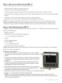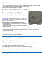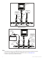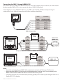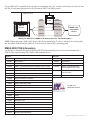
1
GMI 10 Installation Instructions
To obtain the best possible performance, install your GMI 10 Marine Instrument according to the following instructions.
If you experience difficulty during the installation, contact Garmin Product Support, or seek the advice of a professional
installer.
The GMI 10 will communicate with NMEA 2000- or NMEA 0183-compatible sensors and devices, and can show
information such as speed, heading, water depth, and fuel information when connected to the appropriate sensors.
Product Registration
Help us better support you by completing our online registration today. Go to http://my.garmin.com. Keep the original
sales receipt, or a photocopy, in a safe place.
For future reference, write down the serial number assigned to your GMI 10 in the space provided below. The serial
number is located on a sticker on the back of the GMI 10.
Serial number
Contact Garmin
Contact Garmin Product Support if you have any questions while installing or using your GMI 10. In the USA, go to
www.garmin.com/support, or contact Garmin USA by phone at (913) 397.8200 or (800) 800.1020.
In the UK, contact Garmin (Europe) Ltd. by phone at 0808 2380000.
In Europe, go to www.garmin.com/support and click Contact Support for in-country support information, or contact
Garmin (Europe) Ltd. by phone at +44 (0) 870.8501241.
Packing List and Accessories
Before installing your GMI 10, confirm that your package includes the following items. If any parts are missing, contact
your Garmin dealer immediately.
Standard Package
•
•
•
•
•
•
•
•
•
GMI 10 unit
Protective cover
Flush mount hardware
NMEA 0183 data wiring harness
2 NMEA 2000 T-connectors
2 NMEA 2000 terminators (1 male, 1 female)
1 NMEA 2000 drop cable (2 m)
1 NMEA 2000 power cable (2 m), (3 A fuse)
Installation instructions
Optional Accessories
• Additional NMEA 2000 network components
Tools Needed
•
•
•
•
•
•
•
Jigsaw or 3 17/32 in. (90 mm) hole saw,
Drill and drill bits
Center punch and hammer
Scissors
File and sandpaper
Phillips screwdriver
Anti-seize lubricant (optional)
To install and use your GMI 10
1. Select a location (page 2).
2. Flush mount the GMI 10 (page 2.
3. Connect the GMI 10 to the sensors and to power (page 3).
January 2010
190-01168-02 Rev. A
Printed in Taiwan
Step 1: Select a Location for the GMI 10
Consider the following when you select an installation location:
•
•
•
•
Provides optimal viewing as you operate your vessel.
Allows easy access to the keypad on the GMI 10.
Is strong enough to support the weight of the GMI 10 and protect it from excessive vibration or shock.
Allows room for the routing and connection of the cables. There should be at least a 3 inch (8 cm) clearance behind
the case.
• Is at least 9 1/2 in. (241 mm) from a magnetic compass, to avoid interference.
• Mount the GMI 10 in an area that is not exposed to extreme temperature conditions.
NOTE: The temperature range for the GMI 10 is from 5°F to 158°F (from -15°C to 70°C). Extended exposure to
temperatures outside this range (in storage or operating conditions) may cause failure of the LCD screen or other
components. This type of failure and related consequences are not covered by the manufacturer’s limited warranty.
Step 2: Flush Mounting the GMI 10
In addition to four of the included mounting screws (number 8 ANSI (4.2 × 1.4 DIN7981)), flush mounting the GMI 10
requires the following tools:
• Phillips screwdriver
• Drill and 1/8 in. (3.2 mm) drill bit for mounting holes
• 3 17/32 in. (90 mm) hole saw for pilot hole
• Scissors
• Center punch and hammer
• File and sandpaper
• Anti-seize lubricant (optional)
• Counterbore bit (for fiberglass installations)
NOTE: Ensure that the surface on which you mount the GMI 10 has sufficient open space behind it to accommodate
the GMI 10 and the connected wires.
To flush mount the GMI 10:
1. The flush-mount template is included in the product box. Trim the template
and ensure that it will fit in the location at which you want to flush mount the
GMI 10.
2. The flush-mount template has adhesive on the back. Remove the protective
liner and apply the template to the location where you want to flush mount
the GMI 10.
3. Using the 3 17/32 in. (90 mm) hole saw, cut the mounting surface along the
inside of the dashed line indicated on the flush-mount template. Use a file
and sandpaper to refine the size of the hole.
4. Place the GMI 10 into the cutout to confirm that the four mounting-holes are
correct after refining the hole. If not, mark the correct locations of the four
mounting holes. Remove the GMI 10 from the cutout.
5. Using the center punch, indent the center of each of the four mounting-hole locations.
6. Using a 1/8 in. (3.2 mm) drill bit, drill the four mounting holes.
NOTE: If you are mounting the chartplotter in fiberglass, it is recommended to use a countersink bit to drill a
clearance-counterbore through only the top gel-coat layer. This will help to avoid any cracking in the gel-coat layer
when the screws are tightened.
GMI 10 Installation Instructions
7. Place the GMI 10 into the cutout.
8. Securely tighten the four mounting screws through the GMI 10 into the drilled mounting holes.
NOTE: Stainless-steel screws may bind when screwed into fiberglass and overtightened. Garmin recommends
applying an anti-galling, stainless anti-seize lubricant to the screw before using.
9. Install the mounting covers by snapping them into place.
Step 3: Connect the GMI 10 to Sensors and to Power
The GMI 10 can connect to sensors using either NMEA 2000 or NMEA 0183.
Connecting the GMI 10 through NMEA 2000
The GMI 10 is packaged with the necessary NMEA 2000 connectors and
cable to either connect the GMI 10 to your existing NMEA 2000 network or
to build a basic NMEA 2000 network. For more information on NMEA 2000,
visit
www.garmin.com. Follow the directions and reference the diagrams on page
4 to either connect the GMI 10 to your existing NMEA 2000 network or to
build a basic NMEA 2000 network.
To connect the GMI 10 to your existing NMEA 2000 network:
1. Determine where you would like to connect the GMI 10 to your existing
NMEA 2000 backbone.
NMEA 0183
NMEA 2000
Data
2. Disconnect one side of a NMEA 2000 T-connector from the backbone at
an appropriate location.
If you need to extend the NMEA 2000 backbone, connect an appropriate NMEA 2000 backbone extension cable (not
included) to the side of the T-connector you disconnected.
3. Add the included T-connector for the GMI 10 in the NMEA 2000 backbone by connecting it to the side of the T-connector you disconnected.
4. Route the included drop cable to the bottom of the T-connector you just added to your NMEA 2000 network.
If the included drop cable is not long enough, you can use a drop cable up to 20 ft. (6 m) long (not included).
5. Connect the drop cable to the T-connector and the GMI 10.
Notice
If you have an existing NMEA 2000 network on your boat, it should already be connected to power. Do not connect
the included NMEA 2000 power cable to an existing NMEA 2000 network, because only one power source should be
connected to a NMEA 2000 network.
To create a basic NMEA 2000 Network
1. Connect the two T-connectors together by their sides.
2. The included NMEA 2000 power cable must be connected to a 12 Vdc power source through a switch. Connect to
the ignition switch of the boat if possible, or through an appropriate additional switch (not included).
3. Connect the NMEA 2000 power cable to one of the T-connectors.
4. Connect the included NMEA 2000 drop cable to the other T-connector and to the GMI 10.
5. Add additional T-connectors for each sensor (not included) you want to add to the NMEA 2000 network, and connect
each sensor to a T-connector with the appropriate drop cable (not included).
6. Connect the appropriate terminators to each end of the combined T-connectors.
Notice
You must connect the included NMEA 2000 power cable to the ignition switch of the boat, or through an external
switch. The GMI 10 will drain your battery if it is connected directly.
GMI 10 Installation Instructions
GMI 10
NMEA 2000
device
(not included)
NMEA 2000
device
(not included)
Drop cable
(included)
T-connector
(included)
Existing NMEA 2000 network
Connecting the GMI 10 to an Existing NMEA 2000 Network
Ignition or
in-line switch
Fuse
NMEA 2000
device
(not included)
-
+
12 Vdc battery
Power cable
Drop cable
T-connectors
Additional
drop cable and
T-connector
(not included)
Male
terminator
Female
terminator
Creating a Basic NMEA 2000 Network
Notes:
• To add additional sensors to your NMEA 2000 network, follow the instructions included with the sensor.
• To learn more about NMEA 2000 and building a NMEA 2000 network, visit www.garmin.com.
• The GMI 10 is powered by the NMEA 2000 network.
GMI 10 Installation Instructions
Connecting the GMI 10 through NMEA 0183
The GMI 10 can receive NMEA 0183 data from one device. The GMI 10 displays the received data, but cannot transmit
the data to another NMEA 0183 device or transmit the data to a NMEA 2000 network.
Use the diagrams to wire a NMEA 0183 device to your GMI 10. Use 22 AWG, shielded, twisted-pair wiring for
extended runs of wire. Solder all connections and seal them with heat-shrink tubing.
GMI 10 Device
Color
Function
Black
Accessory Off(-)
Yellow
Accessory On(+)
>
Blue
Tx/A(+)
>
White
Tx/B(-)
>
Brown
Rx/A(+)
>
Green
Rx/B(-)
GMI 10 Data Cable
+
WIRE
COLOR
GMI 10 Device
Battery
12 Vdc
WIRE
COLOR
Fuse
RED
RED
1A
BLACK
BLACK
YELLOW
ORANGE
>
BLUE
WHITE
WHITE
WHITE/ ORANGE
>
>
BROWN
>
GREEN
GRAY
WHITE/ RED
GPS 17/17x NMEA 0183 HVS Antenna
>
>
>
>
Wiring the GMI 10 to a GPS 17x NMEA 0183 HVS Antenna
+
WIRE
COLOR
GMI 10 Device
Battery
12 Vdc
WIRE
FUNCTION
POWER
NMEA 0183 Compliant Device
POWER GND
>
BROWN
Tx/A (+)
GREEN
Tx/B (-)
>
>
>
Wiring the GMI 10 to a Standard NMEA 0183 Device
Notes:
• Consult the instructions for your NMEA 0183-compliant device to identify the Tx/A(+) and Tx/ B(-) wires.
• When connecting NMEA 0183 devices with two transmitting and two receiving lines, it is not necessary for the
NMEA 2000 bus and the NMEA 0183 device to connect to a common ground.
• The yellow (accessory on) wire and the black (accessory ground) wire are used only when wiring the GMI 10 to a
Garmin GPS 17/17x antenna.
GMI 10 Installation Instructions
If your NMEA 0183-compatible device has only one transmitting wire (Tx), connect it to the brown wire (Rx/A) from
the GMI 10, and connect the green wire (Rx/B) from the GMI 10 to NMEA ground.
NMEA 2000 network
+
WIRE
COLOR
Battery
12 Vdc
-
WIRE FUNCTION
POWER
GMI 10 Device
>
GREEN
NMEA GND
BLACK
POWER GND
BROWN
Tx
NMEA 0183- Compatible Device
>
Wiring the GMI 10 to a NMEA 0183 Device with One Transmitting Wire
NOTE: When connecting a NMEA 0183 device with only one transmitting (Tx) line or with only one receiving (Rx)
line, the NMEA 2000 bus and the NMEA 0183 device must be connected to a common ground.
NMEA 2000 PGN Information
Use this table to determine the approved NMEA 2000 PGN information that can be received and transmitted by a
GMI 10 when communicating with a NMEA 2000-compliant device.
Receive
Transmit
059392
ISO Acknowledgment
059392
ISO Acknowledgment
059904
ISO Request
059904
ISO Request
060928
ISO Address Claim
060928
ISO Address Claim
126208
NMEA - Command/Request/Acknowledge Group Function
126208
126464
Transmit/Receive PGN List Group Function
NMEA - Command/Request/
Acknowledge Group Function
126992
System Time
126464
126996
Product Information
Transmit/Receive PGN List
Group Function
127250
Vessel Heading
126996
Product Information
127489
Engine Parameters - Dynamic
127505
Fluid Level
128259
Speed - Water Referenced
128267
Water Depth
129025
Position - Rapid Update
129026
COG & SOG - Rapid Update
129029
GNSS Position Data
129044
Datum
129283
Cross Track Error
129284
Navigation Data
129285
Navigation - Route/WP information
129539
GNSS DOPs
129540
GNSS Sats in View
130306
Wind Data
130310
Environmental Parameters
The GMI 10 is
NMEA 2000 certified
GMI 10 Installation Instructions
Receive
Transmit
130311
Environmental Parameters
130312
Temperature
130313
Humidity
130314
Actual Pressure
NMEA 0183 Sentence Information
The GMI 10 can receive the following approved NMEA 0183 sentences from a NMEA 0183-compliant device:
BOD, BWC, DBT, DPT, GGA, GLL, GSA, GSV, HDG, HDM, MDA, MTW, MWD, MWV, RMB, RMC, VHW, WPL,
and XTE.
Specifications
Physical
Dimensions:
W × H × D: 4 5/16 × 4 3/8 × 1 29/32 in (109 × 111 × 48 mm)
Weight:
9.6 oz. (272 g)
Cables: NMEA 0183 data cable - 6 ft. (1.8 m)
NMEA 2000 drop cable and power cable- 6 1/2 ft. (2 m)
Temp range:
From 5°F to 158°F (from -15°C to 70°C)
Compass Safe Distance: 9 1/2 in. (241 mm)
Case Material: Fully gasketed, high-impact plastic alloy, waterproof to IEC 529 IPX7 standards
Power
GMI 10 power usage: 2.5 W max
NMEA 2000 Power Input: 9–16 Vdc
NMEA 2000 Load Equivalency Number (LEN): 6 (300 mA)
Declaration of Conformity
Hereby, Garmin, declares that this product is in compliance with the essential requirements and other
relevant provisions of Directive 1999/5/EC. To view the full Declaration of Conformity, go to
www.garmin.com/declaration-of-conformity.
Software License Agreement
BY USING THE GMI 10, YOU AGREE TO BE BOUND BY THE TERMS AND CONDITIONS OF THE FOLLOWING SOFTWARE
LICENSE AGREEMENT. PLEASE READ THIS AGREEMENT CAREFULLY.
Garmin Ltd. and its subsidiaries (“Garmin”) grant you a limited license to use the software embedded in this device (the “Software”) in binary
executable form in the normal operation of the product. Title, ownership rights, and intellectual property rights in and to the Software remain in
Garmin and/or its third-party providers.
You acknowledge that the Software is the property of Garmin and/or its third-party providers and is protected under the United States of America
copyright laws and international copyright treaties. You further acknowledge that the structure, organization, and code of the Software, for which
source code is not provided, are valuable trade secrets of Garmin and/or its third-party providers and that the Software in source code form
remains a valuable trade secret of Garmin and/or its third-party providers. You agree not to decompile, disassemble, modify, reverse assemble,
reverse engineer, or reduce to human readable form the Software or any part thereof or create any derivative works based on the Software. You
agree not to export or re-export the Software to any country in violation of the export control laws of the United States of America or the export
control laws of any other applicable country.
GMI 10 Installation Instructions
For the latest free software updates (excluding map data) throughout the life of your Garmin products, visit the Garmin Web site at www.garmin.com.
© 2010 Garmin Ltd. or its subsidiaries
Garmin International, Inc.
1200 East 151st Street, Olathe, Kansas 66062, USA
Garmin (Europe) Ltd.
Liberty House, Hounsdown Business Park, Southampton, Hampshire, SO40 9LR UK
Garmin Corporation
No. 68, Jangshu 2nd Road, Sijhih, Taipei County, Taiwan
www.garmin.com
January 2010
Part Number 190-01168-02 Rev. A
Printed in Taiwan